EP3751181B1 - Procédé de fonctionnement d'un véhicule - Google Patents
Procédé de fonctionnement d'un véhicule Download PDFInfo
- Publication number
- EP3751181B1 EP3751181B1 EP20177734.9A EP20177734A EP3751181B1 EP 3751181 B1 EP3751181 B1 EP 3751181B1 EP 20177734 A EP20177734 A EP 20177734A EP 3751181 B1 EP3751181 B1 EP 3751181B1
- Authority
- EP
- European Patent Office
- Prior art keywords
- engine
- piston
- piston force
- speed
- throttle
- Prior art date
- Legal status (The legal status is an assumption and is not a legal conclusion. Google has not performed a legal analysis and makes no representation as to the accuracy of the status listed.)
- Active
Links
- 238000000034 method Methods 0.000 title claims description 30
- 230000001276 controlling effect Effects 0.000 claims description 16
- 230000005540 biological transmission Effects 0.000 claims description 9
- 238000001514 detection method Methods 0.000 claims description 3
- 230000001105 regulatory effect Effects 0.000 claims description 2
- 241000239290 Araneae Species 0.000 description 20
- 239000000446 fuel Substances 0.000 description 19
- 230000006870 function Effects 0.000 description 18
- 238000005516 engineering process Methods 0.000 description 14
- 230000008859 change Effects 0.000 description 9
- 230000009467 reduction Effects 0.000 description 9
- 230000004044 response Effects 0.000 description 9
- 239000000725 suspension Substances 0.000 description 8
- 230000007423 decrease Effects 0.000 description 7
- 238000002347 injection Methods 0.000 description 6
- 239000007924 injection Substances 0.000 description 6
- 230000007246 mechanism Effects 0.000 description 5
- 238000000926 separation method Methods 0.000 description 5
- 230000005355 Hall effect Effects 0.000 description 4
- 238000002485 combustion reaction Methods 0.000 description 4
- 239000000203 mixture Substances 0.000 description 4
- 238000004891 communication Methods 0.000 description 3
- 238000010276 construction Methods 0.000 description 3
- 238000001816 cooling Methods 0.000 description 3
- 239000002828 fuel tank Substances 0.000 description 3
- 230000001133 acceleration Effects 0.000 description 2
- 230000009471 action Effects 0.000 description 2
- 229910052782 aluminium Inorganic materials 0.000 description 2
- XAGFODPZIPBFFR-UHFFFAOYSA-N aluminium Chemical compound [Al] XAGFODPZIPBFFR-UHFFFAOYSA-N 0.000 description 2
- 230000000295 complement effect Effects 0.000 description 2
- 239000002826 coolant Substances 0.000 description 2
- 230000003247 decreasing effect Effects 0.000 description 2
- 239000012530 fluid Substances 0.000 description 2
- 239000000463 material Substances 0.000 description 2
- 238000012544 monitoring process Methods 0.000 description 2
- 239000006096 absorbing agent Substances 0.000 description 1
- 230000004913 activation Effects 0.000 description 1
- 238000013475 authorization Methods 0.000 description 1
- 230000008901 benefit Effects 0.000 description 1
- 230000033228 biological regulation Effects 0.000 description 1
- 230000006835 compression Effects 0.000 description 1
- 238000007906 compression Methods 0.000 description 1
- 230000001419 dependent effect Effects 0.000 description 1
- 238000010586 diagram Methods 0.000 description 1
- 238000006073 displacement reaction Methods 0.000 description 1
- 210000003811 finger Anatomy 0.000 description 1
- 230000005484 gravity Effects 0.000 description 1
- 230000006872 improvement Effects 0.000 description 1
- 238000007689 inspection Methods 0.000 description 1
- 238000012423 maintenance Methods 0.000 description 1
- 229910052751 metal Inorganic materials 0.000 description 1
- 239000002184 metal Substances 0.000 description 1
- 238000012986 modification Methods 0.000 description 1
- 230000004048 modification Effects 0.000 description 1
- 230000008569 process Effects 0.000 description 1
- 230000035939 shock Effects 0.000 description 1
- 210000003813 thumb Anatomy 0.000 description 1
- 238000012546 transfer Methods 0.000 description 1
- 238000013022 venting Methods 0.000 description 1
- XLYOFNOQVPJJNP-UHFFFAOYSA-N water Substances O XLYOFNOQVPJJNP-UHFFFAOYSA-N 0.000 description 1
- 239000013585 weight reducing agent Substances 0.000 description 1
Images


Classifications
-
- B—PERFORMING OPERATIONS; TRANSPORTING
- B60—VEHICLES IN GENERAL
- B60W—CONJOINT CONTROL OF VEHICLE SUB-UNITS OF DIFFERENT TYPE OR DIFFERENT FUNCTION; CONTROL SYSTEMS SPECIALLY ADAPTED FOR HYBRID VEHICLES; ROAD VEHICLE DRIVE CONTROL SYSTEMS FOR PURPOSES NOT RELATED TO THE CONTROL OF A PARTICULAR SUB-UNIT
- B60W10/00—Conjoint control of vehicle sub-units of different type or different function
- B60W10/10—Conjoint control of vehicle sub-units of different type or different function including control of change-speed gearings
- B60W10/101—Infinitely variable gearings
-
- B—PERFORMING OPERATIONS; TRANSPORTING
- B62—LAND VEHICLES FOR TRAVELLING OTHERWISE THAN ON RAILS
- B62J—CYCLE SADDLES OR SEATS; AUXILIARY DEVICES OR ACCESSORIES SPECIALLY ADAPTED TO CYCLES AND NOT OTHERWISE PROVIDED FOR, e.g. ARTICLE CARRIERS OR CYCLE PROTECTORS
- B62J45/00—Electrical equipment arrangements specially adapted for use as accessories on cycles, not otherwise provided for
- B62J45/40—Sensor arrangements; Mounting thereof
- B62J45/41—Sensor arrangements; Mounting thereof characterised by the type of sensor
- B62J45/412—Speed sensors
-
- B—PERFORMING OPERATIONS; TRANSPORTING
- B60—VEHICLES IN GENERAL
- B60W—CONJOINT CONTROL OF VEHICLE SUB-UNITS OF DIFFERENT TYPE OR DIFFERENT FUNCTION; CONTROL SYSTEMS SPECIALLY ADAPTED FOR HYBRID VEHICLES; ROAD VEHICLE DRIVE CONTROL SYSTEMS FOR PURPOSES NOT RELATED TO THE CONTROL OF A PARTICULAR SUB-UNIT
- B60W10/00—Conjoint control of vehicle sub-units of different type or different function
- B60W10/04—Conjoint control of vehicle sub-units of different type or different function including control of propulsion units
- B60W10/06—Conjoint control of vehicle sub-units of different type or different function including control of propulsion units including control of combustion engines
-
- B—PERFORMING OPERATIONS; TRANSPORTING
- B60—VEHICLES IN GENERAL
- B60W—CONJOINT CONTROL OF VEHICLE SUB-UNITS OF DIFFERENT TYPE OR DIFFERENT FUNCTION; CONTROL SYSTEMS SPECIALLY ADAPTED FOR HYBRID VEHICLES; ROAD VEHICLE DRIVE CONTROL SYSTEMS FOR PURPOSES NOT RELATED TO THE CONTROL OF A PARTICULAR SUB-UNIT
- B60W10/00—Conjoint control of vehicle sub-units of different type or different function
- B60W10/10—Conjoint control of vehicle sub-units of different type or different function including control of change-speed gearings
- B60W10/101—Infinitely variable gearings
- B60W10/107—Infinitely variable gearings with endless flexible members
-
- B—PERFORMING OPERATIONS; TRANSPORTING
- B60—VEHICLES IN GENERAL
- B60W—CONJOINT CONTROL OF VEHICLE SUB-UNITS OF DIFFERENT TYPE OR DIFFERENT FUNCTION; CONTROL SYSTEMS SPECIALLY ADAPTED FOR HYBRID VEHICLES; ROAD VEHICLE DRIVE CONTROL SYSTEMS FOR PURPOSES NOT RELATED TO THE CONTROL OF A PARTICULAR SUB-UNIT
- B60W30/00—Purposes of road vehicle drive control systems not related to the control of a particular sub-unit, e.g. of systems using conjoint control of vehicle sub-units, or advanced driver assistance systems for ensuring comfort, stability and safety or drive control systems for propelling or retarding the vehicle
- B60W30/18—Propelling the vehicle
- B60W30/188—Controlling power parameters of the driveline, e.g. determining the required power
- B60W30/1882—Controlling power parameters of the driveline, e.g. determining the required power characterised by the working point of the engine, e.g. by using engine output chart
-
- B—PERFORMING OPERATIONS; TRANSPORTING
- B60—VEHICLES IN GENERAL
- B60W—CONJOINT CONTROL OF VEHICLE SUB-UNITS OF DIFFERENT TYPE OR DIFFERENT FUNCTION; CONTROL SYSTEMS SPECIALLY ADAPTED FOR HYBRID VEHICLES; ROAD VEHICLE DRIVE CONTROL SYSTEMS FOR PURPOSES NOT RELATED TO THE CONTROL OF A PARTICULAR SUB-UNIT
- B60W40/00—Estimation or calculation of non-directly measurable driving parameters for road vehicle drive control systems not related to the control of a particular sub unit, e.g. by using mathematical models
- B60W40/02—Estimation or calculation of non-directly measurable driving parameters for road vehicle drive control systems not related to the control of a particular sub unit, e.g. by using mathematical models related to ambient conditions
-
- B—PERFORMING OPERATIONS; TRANSPORTING
- B60—VEHICLES IN GENERAL
- B60W—CONJOINT CONTROL OF VEHICLE SUB-UNITS OF DIFFERENT TYPE OR DIFFERENT FUNCTION; CONTROL SYSTEMS SPECIALLY ADAPTED FOR HYBRID VEHICLES; ROAD VEHICLE DRIVE CONTROL SYSTEMS FOR PURPOSES NOT RELATED TO THE CONTROL OF A PARTICULAR SUB-UNIT
- B60W50/00—Details of control systems for road vehicle drive control not related to the control of a particular sub-unit, e.g. process diagnostic or vehicle driver interfaces
- B60W50/08—Interaction between the driver and the control system
- B60W50/082—Selecting or switching between different modes of propelling
-
- B—PERFORMING OPERATIONS; TRANSPORTING
- B62—LAND VEHICLES FOR TRAVELLING OTHERWISE THAN ON RAILS
- B62M—RIDER PROPULSION OF WHEELED VEHICLES OR SLEDGES; POWERED PROPULSION OF SLEDGES OR SINGLE-TRACK CYCLES; TRANSMISSIONS SPECIALLY ADAPTED FOR SUCH VEHICLES
- B62M27/00—Propulsion devices for sledges or the like
- B62M27/02—Propulsion devices for sledges or the like power driven
-
- B—PERFORMING OPERATIONS; TRANSPORTING
- B62—LAND VEHICLES FOR TRAVELLING OTHERWISE THAN ON RAILS
- B62M—RIDER PROPULSION OF WHEELED VEHICLES OR SLEDGES; POWERED PROPULSION OF SLEDGES OR SINGLE-TRACK CYCLES; TRANSMISSIONS SPECIALLY ADAPTED FOR SUCH VEHICLES
- B62M9/00—Transmissions characterised by use of an endless chain, belt, or the like
- B62M9/04—Transmissions characterised by use of an endless chain, belt, or the like of changeable ratio
- B62M9/06—Transmissions characterised by use of an endless chain, belt, or the like of changeable ratio using a single chain, belt, or the like
- B62M9/08—Transmissions characterised by use of an endless chain, belt, or the like of changeable ratio using a single chain, belt, or the like involving eccentrically- mounted or elliptically-shaped driving or driven wheel; with expansible driving or driven wheel
-
- F—MECHANICAL ENGINEERING; LIGHTING; HEATING; WEAPONS; BLASTING
- F16—ENGINEERING ELEMENTS AND UNITS; GENERAL MEASURES FOR PRODUCING AND MAINTAINING EFFECTIVE FUNCTIONING OF MACHINES OR INSTALLATIONS; THERMAL INSULATION IN GENERAL
- F16H—GEARING
- F16H59/00—Control inputs to control units of change-speed-, or reversing-gearings for conveying rotary motion
- F16H59/14—Inputs being a function of torque or torque demand
- F16H59/24—Inputs being a function of torque or torque demand dependent on the throttle opening
-
- F—MECHANICAL ENGINEERING; LIGHTING; HEATING; WEAPONS; BLASTING
- F16—ENGINEERING ELEMENTS AND UNITS; GENERAL MEASURES FOR PRODUCING AND MAINTAINING EFFECTIVE FUNCTIONING OF MACHINES OR INSTALLATIONS; THERMAL INSULATION IN GENERAL
- F16H—GEARING
- F16H59/00—Control inputs to control units of change-speed-, or reversing-gearings for conveying rotary motion
- F16H59/36—Inputs being a function of speed
- F16H59/38—Inputs being a function of speed of gearing elements
- F16H59/40—Output shaft speed
-
- F—MECHANICAL ENGINEERING; LIGHTING; HEATING; WEAPONS; BLASTING
- F16—ENGINEERING ELEMENTS AND UNITS; GENERAL MEASURES FOR PRODUCING AND MAINTAINING EFFECTIVE FUNCTIONING OF MACHINES OR INSTALLATIONS; THERMAL INSULATION IN GENERAL
- F16H—GEARING
- F16H59/00—Control inputs to control units of change-speed-, or reversing-gearings for conveying rotary motion
- F16H59/50—Inputs being a function of the status of the machine, e.g. position of doors or safety belts
- F16H59/54—Inputs being a function of the status of the machine, e.g. position of doors or safety belts dependent on signals from the brakes, e.g. parking brakes
-
- F—MECHANICAL ENGINEERING; LIGHTING; HEATING; WEAPONS; BLASTING
- F16—ENGINEERING ELEMENTS AND UNITS; GENERAL MEASURES FOR PRODUCING AND MAINTAINING EFFECTIVE FUNCTIONING OF MACHINES OR INSTALLATIONS; THERMAL INSULATION IN GENERAL
- F16H—GEARING
- F16H59/00—Control inputs to control units of change-speed-, or reversing-gearings for conveying rotary motion
- F16H59/60—Inputs being a function of ambient conditions
- F16H59/62—Atmospheric pressure
-
- F—MECHANICAL ENGINEERING; LIGHTING; HEATING; WEAPONS; BLASTING
- F16—ENGINEERING ELEMENTS AND UNITS; GENERAL MEASURES FOR PRODUCING AND MAINTAINING EFFECTIVE FUNCTIONING OF MACHINES OR INSTALLATIONS; THERMAL INSULATION IN GENERAL
- F16H—GEARING
- F16H61/00—Control functions within control units of change-speed- or reversing-gearings for conveying rotary motion ; Control of exclusively fluid gearing, friction gearing, gearings with endless flexible members or other particular types of gearing
- F16H61/66—Control functions within control units of change-speed- or reversing-gearings for conveying rotary motion ; Control of exclusively fluid gearing, friction gearing, gearings with endless flexible members or other particular types of gearing specially adapted for continuously variable gearings
- F16H61/662—Control functions within control units of change-speed- or reversing-gearings for conveying rotary motion ; Control of exclusively fluid gearing, friction gearing, gearings with endless flexible members or other particular types of gearing specially adapted for continuously variable gearings with endless flexible members
- F16H61/66272—Control functions within control units of change-speed- or reversing-gearings for conveying rotary motion ; Control of exclusively fluid gearing, friction gearing, gearings with endless flexible members or other particular types of gearing specially adapted for continuously variable gearings with endless flexible members characterised by means for controlling the torque transmitting capability of the gearing
-
- F—MECHANICAL ENGINEERING; LIGHTING; HEATING; WEAPONS; BLASTING
- F16—ENGINEERING ELEMENTS AND UNITS; GENERAL MEASURES FOR PRODUCING AND MAINTAINING EFFECTIVE FUNCTIONING OF MACHINES OR INSTALLATIONS; THERMAL INSULATION IN GENERAL
- F16H—GEARING
- F16H9/00—Gearings for conveying rotary motion with variable gear ratio, or for reversing rotary motion, by endless flexible members
- F16H9/02—Gearings for conveying rotary motion with variable gear ratio, or for reversing rotary motion, by endless flexible members without members having orbital motion
- F16H9/04—Gearings for conveying rotary motion with variable gear ratio, or for reversing rotary motion, by endless flexible members without members having orbital motion using belts, V-belts, or ropes
- F16H9/12—Gearings for conveying rotary motion with variable gear ratio, or for reversing rotary motion, by endless flexible members without members having orbital motion using belts, V-belts, or ropes engaging a pulley built-up out of relatively axially-adjustable parts in which the belt engages the opposite flanges of the pulley directly without interposed belt-supporting members
- F16H9/14—Gearings for conveying rotary motion with variable gear ratio, or for reversing rotary motion, by endless flexible members without members having orbital motion using belts, V-belts, or ropes engaging a pulley built-up out of relatively axially-adjustable parts in which the belt engages the opposite flanges of the pulley directly without interposed belt-supporting members using only one pulley built-up out of adjustable conical parts
-
- B—PERFORMING OPERATIONS; TRANSPORTING
- B60—VEHICLES IN GENERAL
- B60W—CONJOINT CONTROL OF VEHICLE SUB-UNITS OF DIFFERENT TYPE OR DIFFERENT FUNCTION; CONTROL SYSTEMS SPECIALLY ADAPTED FOR HYBRID VEHICLES; ROAD VEHICLE DRIVE CONTROL SYSTEMS FOR PURPOSES NOT RELATED TO THE CONTROL OF A PARTICULAR SUB-UNIT
- B60W2510/00—Input parameters relating to a particular sub-units
- B60W2510/06—Combustion engines, Gas turbines
- B60W2510/0604—Throttle position
-
- B—PERFORMING OPERATIONS; TRANSPORTING
- B60—VEHICLES IN GENERAL
- B60W—CONJOINT CONTROL OF VEHICLE SUB-UNITS OF DIFFERENT TYPE OR DIFFERENT FUNCTION; CONTROL SYSTEMS SPECIALLY ADAPTED FOR HYBRID VEHICLES; ROAD VEHICLE DRIVE CONTROL SYSTEMS FOR PURPOSES NOT RELATED TO THE CONTROL OF A PARTICULAR SUB-UNIT
- B60W2510/00—Input parameters relating to a particular sub-units
- B60W2510/06—Combustion engines, Gas turbines
- B60W2510/0638—Engine speed
-
- B—PERFORMING OPERATIONS; TRANSPORTING
- B60—VEHICLES IN GENERAL
- B60W—CONJOINT CONTROL OF VEHICLE SUB-UNITS OF DIFFERENT TYPE OR DIFFERENT FUNCTION; CONTROL SYSTEMS SPECIALLY ADAPTED FOR HYBRID VEHICLES; ROAD VEHICLE DRIVE CONTROL SYSTEMS FOR PURPOSES NOT RELATED TO THE CONTROL OF A PARTICULAR SUB-UNIT
- B60W2510/00—Input parameters relating to a particular sub-units
- B60W2510/06—Combustion engines, Gas turbines
- B60W2510/0676—Engine temperature
-
- B—PERFORMING OPERATIONS; TRANSPORTING
- B60—VEHICLES IN GENERAL
- B60W—CONJOINT CONTROL OF VEHICLE SUB-UNITS OF DIFFERENT TYPE OR DIFFERENT FUNCTION; CONTROL SYSTEMS SPECIALLY ADAPTED FOR HYBRID VEHICLES; ROAD VEHICLE DRIVE CONTROL SYSTEMS FOR PURPOSES NOT RELATED TO THE CONTROL OF A PARTICULAR SUB-UNIT
- B60W2510/00—Input parameters relating to a particular sub-units
- B60W2510/10—Change speed gearings
- B60W2510/104—Output speed
-
- B—PERFORMING OPERATIONS; TRANSPORTING
- B60—VEHICLES IN GENERAL
- B60W—CONJOINT CONTROL OF VEHICLE SUB-UNITS OF DIFFERENT TYPE OR DIFFERENT FUNCTION; CONTROL SYSTEMS SPECIALLY ADAPTED FOR HYBRID VEHICLES; ROAD VEHICLE DRIVE CONTROL SYSTEMS FOR PURPOSES NOT RELATED TO THE CONTROL OF A PARTICULAR SUB-UNIT
- B60W2520/00—Input parameters relating to overall vehicle dynamics
- B60W2520/10—Longitudinal speed
-
- B—PERFORMING OPERATIONS; TRANSPORTING
- B60—VEHICLES IN GENERAL
- B60W—CONJOINT CONTROL OF VEHICLE SUB-UNITS OF DIFFERENT TYPE OR DIFFERENT FUNCTION; CONTROL SYSTEMS SPECIALLY ADAPTED FOR HYBRID VEHICLES; ROAD VEHICLE DRIVE CONTROL SYSTEMS FOR PURPOSES NOT RELATED TO THE CONTROL OF A PARTICULAR SUB-UNIT
- B60W2540/00—Input parameters relating to occupants
- B60W2540/10—Accelerator pedal position
-
- B—PERFORMING OPERATIONS; TRANSPORTING
- B60—VEHICLES IN GENERAL
- B60W—CONJOINT CONTROL OF VEHICLE SUB-UNITS OF DIFFERENT TYPE OR DIFFERENT FUNCTION; CONTROL SYSTEMS SPECIALLY ADAPTED FOR HYBRID VEHICLES; ROAD VEHICLE DRIVE CONTROL SYSTEMS FOR PURPOSES NOT RELATED TO THE CONTROL OF A PARTICULAR SUB-UNIT
- B60W2552/00—Input parameters relating to infrastructure
- B60W2552/15—Road slope
-
- B—PERFORMING OPERATIONS; TRANSPORTING
- B60—VEHICLES IN GENERAL
- B60W—CONJOINT CONTROL OF VEHICLE SUB-UNITS OF DIFFERENT TYPE OR DIFFERENT FUNCTION; CONTROL SYSTEMS SPECIALLY ADAPTED FOR HYBRID VEHICLES; ROAD VEHICLE DRIVE CONTROL SYSTEMS FOR PURPOSES NOT RELATED TO THE CONTROL OF A PARTICULAR SUB-UNIT
- B60W2555/00—Input parameters relating to exterior conditions, not covered by groups B60W2552/00, B60W2554/00
- B60W2555/40—Altitude
-
- B—PERFORMING OPERATIONS; TRANSPORTING
- B60—VEHICLES IN GENERAL
- B60W—CONJOINT CONTROL OF VEHICLE SUB-UNITS OF DIFFERENT TYPE OR DIFFERENT FUNCTION; CONTROL SYSTEMS SPECIALLY ADAPTED FOR HYBRID VEHICLES; ROAD VEHICLE DRIVE CONTROL SYSTEMS FOR PURPOSES NOT RELATED TO THE CONTROL OF A PARTICULAR SUB-UNIT
- B60W2710/00—Output or target parameters relating to a particular sub-units
- B60W2710/10—Change speed gearings
- B60W2710/1077—Change speed gearings fluid pressure, e.g. oil pressure
-
- B—PERFORMING OPERATIONS; TRANSPORTING
- B60—VEHICLES IN GENERAL
- B60W—CONJOINT CONTROL OF VEHICLE SUB-UNITS OF DIFFERENT TYPE OR DIFFERENT FUNCTION; CONTROL SYSTEMS SPECIALLY ADAPTED FOR HYBRID VEHICLES; ROAD VEHICLE DRIVE CONTROL SYSTEMS FOR PURPOSES NOT RELATED TO THE CONTROL OF A PARTICULAR SUB-UNIT
- B60W30/00—Purposes of road vehicle drive control systems not related to the control of a particular sub-unit, e.g. of systems using conjoint control of vehicle sub-units, or advanced driver assistance systems for ensuring comfort, stability and safety or drive control systems for propelling or retarding the vehicle
- B60W30/18—Propelling the vehicle
- B60W30/18009—Propelling the vehicle related to particular drive situations
- B60W30/18018—Start-stop drive, e.g. in a traffic jam
-
- B—PERFORMING OPERATIONS; TRANSPORTING
- B60—VEHICLES IN GENERAL
- B60W—CONJOINT CONTROL OF VEHICLE SUB-UNITS OF DIFFERENT TYPE OR DIFFERENT FUNCTION; CONTROL SYSTEMS SPECIALLY ADAPTED FOR HYBRID VEHICLES; ROAD VEHICLE DRIVE CONTROL SYSTEMS FOR PURPOSES NOT RELATED TO THE CONTROL OF A PARTICULAR SUB-UNIT
- B60W30/00—Purposes of road vehicle drive control systems not related to the control of a particular sub-unit, e.g. of systems using conjoint control of vehicle sub-units, or advanced driver assistance systems for ensuring comfort, stability and safety or drive control systems for propelling or retarding the vehicle
- B60W30/18—Propelling the vehicle
- B60W30/18009—Propelling the vehicle related to particular drive situations
- B60W30/18027—Drive off, accelerating from standstill
-
- B—PERFORMING OPERATIONS; TRANSPORTING
- B60—VEHICLES IN GENERAL
- B60W—CONJOINT CONTROL OF VEHICLE SUB-UNITS OF DIFFERENT TYPE OR DIFFERENT FUNCTION; CONTROL SYSTEMS SPECIALLY ADAPTED FOR HYBRID VEHICLES; ROAD VEHICLE DRIVE CONTROL SYSTEMS FOR PURPOSES NOT RELATED TO THE CONTROL OF A PARTICULAR SUB-UNIT
- B60W30/00—Purposes of road vehicle drive control systems not related to the control of a particular sub-unit, e.g. of systems using conjoint control of vehicle sub-units, or advanced driver assistance systems for ensuring comfort, stability and safety or drive control systems for propelling or retarding the vehicle
- B60W30/18—Propelling the vehicle
- B60W30/18009—Propelling the vehicle related to particular drive situations
- B60W30/18072—Coasting
-
- B—PERFORMING OPERATIONS; TRANSPORTING
- B60—VEHICLES IN GENERAL
- B60W—CONJOINT CONTROL OF VEHICLE SUB-UNITS OF DIFFERENT TYPE OR DIFFERENT FUNCTION; CONTROL SYSTEMS SPECIALLY ADAPTED FOR HYBRID VEHICLES; ROAD VEHICLE DRIVE CONTROL SYSTEMS FOR PURPOSES NOT RELATED TO THE CONTROL OF A PARTICULAR SUB-UNIT
- B60W30/00—Purposes of road vehicle drive control systems not related to the control of a particular sub-unit, e.g. of systems using conjoint control of vehicle sub-units, or advanced driver assistance systems for ensuring comfort, stability and safety or drive control systems for propelling or retarding the vehicle
- B60W30/18—Propelling the vehicle
- B60W30/18009—Propelling the vehicle related to particular drive situations
- B60W30/181—Preparing for stopping
-
- B—PERFORMING OPERATIONS; TRANSPORTING
- B62—LAND VEHICLES FOR TRAVELLING OTHERWISE THAN ON RAILS
- B62J—CYCLE SADDLES OR SEATS; AUXILIARY DEVICES OR ACCESSORIES SPECIALLY ADAPTED TO CYCLES AND NOT OTHERWISE PROVIDED FOR, e.g. ARTICLE CARRIERS OR CYCLE PROTECTORS
- B62J45/00—Electrical equipment arrangements specially adapted for use as accessories on cycles, not otherwise provided for
- B62J45/40—Sensor arrangements; Mounting thereof
- B62J45/41—Sensor arrangements; Mounting thereof characterised by the type of sensor
- B62J45/411—Torque sensors
-
- B—PERFORMING OPERATIONS; TRANSPORTING
- B62—LAND VEHICLES FOR TRAVELLING OTHERWISE THAN ON RAILS
- B62J—CYCLE SADDLES OR SEATS; AUXILIARY DEVICES OR ACCESSORIES SPECIALLY ADAPTED TO CYCLES AND NOT OTHERWISE PROVIDED FOR, e.g. ARTICLE CARRIERS OR CYCLE PROTECTORS
- B62J45/00—Electrical equipment arrangements specially adapted for use as accessories on cycles, not otherwise provided for
- B62J45/40—Sensor arrangements; Mounting thereof
- B62J45/41—Sensor arrangements; Mounting thereof characterised by the type of sensor
- B62J45/414—Acceleration sensors
-
- B—PERFORMING OPERATIONS; TRANSPORTING
- B62—LAND VEHICLES FOR TRAVELLING OTHERWISE THAN ON RAILS
- B62J—CYCLE SADDLES OR SEATS; AUXILIARY DEVICES OR ACCESSORIES SPECIALLY ADAPTED TO CYCLES AND NOT OTHERWISE PROVIDED FOR, e.g. ARTICLE CARRIERS OR CYCLE PROTECTORS
- B62J45/00—Electrical equipment arrangements specially adapted for use as accessories on cycles, not otherwise provided for
- B62J45/40—Sensor arrangements; Mounting thereof
- B62J45/41—Sensor arrangements; Mounting thereof characterised by the type of sensor
- B62J45/415—Inclination sensors
- B62J45/4152—Inclination sensors for sensing longitudinal inclination of the cycle
-
- F—MECHANICAL ENGINEERING; LIGHTING; HEATING; WEAPONS; BLASTING
- F16—ENGINEERING ELEMENTS AND UNITS; GENERAL MEASURES FOR PRODUCING AND MAINTAINING EFFECTIVE FUNCTIONING OF MACHINES OR INSTALLATIONS; THERMAL INSULATION IN GENERAL
- F16H—GEARING
- F16H59/00—Control inputs to control units of change-speed-, or reversing-gearings for conveying rotary motion
- F16H59/36—Inputs being a function of speed
- F16H2059/366—Engine or motor speed
-
- F—MECHANICAL ENGINEERING; LIGHTING; HEATING; WEAPONS; BLASTING
- F16—ENGINEERING ELEMENTS AND UNITS; GENERAL MEASURES FOR PRODUCING AND MAINTAINING EFFECTIVE FUNCTIONING OF MACHINES OR INSTALLATIONS; THERMAL INSULATION IN GENERAL
- F16H—GEARING
- F16H59/00—Control inputs to control units of change-speed-, or reversing-gearings for conveying rotary motion
- F16H59/36—Inputs being a function of speed
- F16H59/44—Inputs being a function of speed dependent on machine speed of the machine, e.g. the vehicle
- F16H2059/446—Detecting vehicle stop, i.e. the vehicle is at stand still, e.g. for engaging parking lock
-
- F—MECHANICAL ENGINEERING; LIGHTING; HEATING; WEAPONS; BLASTING
- F16—ENGINEERING ELEMENTS AND UNITS; GENERAL MEASURES FOR PRODUCING AND MAINTAINING EFFECTIVE FUNCTIONING OF MACHINES OR INSTALLATIONS; THERMAL INSULATION IN GENERAL
- F16H—GEARING
- F16H59/00—Control inputs to control units of change-speed-, or reversing-gearings for conveying rotary motion
- F16H59/60—Inputs being a function of ambient conditions
- F16H59/66—Road conditions, e.g. slope, slippery
- F16H2059/663—Road slope
-
- F—MECHANICAL ENGINEERING; LIGHTING; HEATING; WEAPONS; BLASTING
- F16—ENGINEERING ELEMENTS AND UNITS; GENERAL MEASURES FOR PRODUCING AND MAINTAINING EFFECTIVE FUNCTIONING OF MACHINES OR INSTALLATIONS; THERMAL INSULATION IN GENERAL
- F16H—GEARING
- F16H61/00—Control functions within control units of change-speed- or reversing-gearings for conveying rotary motion ; Control of exclusively fluid gearing, friction gearing, gearings with endless flexible members or other particular types of gearing
- F16H61/66—Control functions within control units of change-speed- or reversing-gearings for conveying rotary motion ; Control of exclusively fluid gearing, friction gearing, gearings with endless flexible members or other particular types of gearing specially adapted for continuously variable gearings
- F16H61/662—Control functions within control units of change-speed- or reversing-gearings for conveying rotary motion ; Control of exclusively fluid gearing, friction gearing, gearings with endless flexible members or other particular types of gearing specially adapted for continuously variable gearings with endless flexible members
- F16H2061/66204—Control for modifying the ratio control characteristic
- F16H2061/66209—Control for modifying the ratio control characteristic dependent on ambient conditions
-
- F—MECHANICAL ENGINEERING; LIGHTING; HEATING; WEAPONS; BLASTING
- F16—ENGINEERING ELEMENTS AND UNITS; GENERAL MEASURES FOR PRODUCING AND MAINTAINING EFFECTIVE FUNCTIONING OF MACHINES OR INSTALLATIONS; THERMAL INSULATION IN GENERAL
- F16H—GEARING
- F16H2312/00—Driving activities
- F16H2312/04—Holding or hillholding
Definitions
- the present technology relates generally to a continuously variable transmission and to vehicle control methods.
- JP H05 180302 A and US 2014/004984 A1 disclose centrifugal continuous variable transmissions of the related art.
- Endless belt type continuously variable transmissions are used in many types of vehicles such as snowmobiles, all terrain vehicles (ATVs), scooters and the like to obtain an infinite number of gear ratios between the engine and the vehicle's wheels.
- the CVTs are mechanically controlled by means of centrifugal weights (usually on the driving side) acting against the force of a spring to provide the desired gear ratios.
- CVT characteristics including variation of the gear ratio as a function of engine speed, vehicle speed, torque and the like, can be tailored by appropriate choice of flyweights and spring on the driving side, and the cams on the driven side.
- Mechanically controlled CVTs have limited control options as the configuration of the different components cannot be changed on-the-fly based on operating conditions. Mechanically controlled CVTs can have poor power efficiency due to frictional losses arising from the belted construction. Furthermore, when driving at constant high speeds, the engine, and other related elements inside the engine, operating at high rotational speeds (RPM) cause undesirable noise and vibrations, as well as high fuel consumption.
- RPM rotational speeds
- a method of operating a vehicle includes an engine, a throttle operator being operable by a driver of the vehicle, a throttle valve regulating airflow to the engine, a throttle valve position of the throttle valve being based at least in part on a throttle operator position of the throttle operator, and a continuously variable transmission (CVT) operatively connected to the engine.
- the CVT includes a driving pulley, a driven pulley, and a belt operatively connecting the driving pulley to the driven pulley.
- At least one ground engaging member operatively connects to the driven pulley and includes at least one of: a wheel and a track.
- a piston is operatively connected to the driving pulley for applying a piston force to the driving pulley when actuated, and thereby changing an effective diameter of the driving pulley.
- a control unit controls actuation of the piston and the piston force. The method includes determining a driven pulley speed of the driven pulley. An uphill stand condition indicative of the vehicle being stopped on an uphill is detected and responsive to the detection of the uphill stand condition, the piston force is controlled based on the driven pulley speed.
- the vehicle further includes a brake operatively connected to the at least one ground engaging member.
- the uphill stand condition includes an actuation of the brake followed by a deactuation of the brake, and at least one of the throttle operator position being lower than an uphill stand throttle operator threshold and the throttle valve position being lower than an uphill stand throttle valve threshold.
- an inclination of the ground is sensed and the uphill stand condition further includes the sensed inclination being uphill.
- controlling the piston force includes, responsive to the driven pulley speed being negative, increasing the piston force until at least one of the following occurs: the driven pulley speed becomes zero, and the piston force becomes equal to a maximum piston force.
- the piston force is increased at a rate such that the piston force increases to the maximum piston force within an uphill stand threshold time period.
- the uphill stand threshold time period is one second.
- the piston is at least one of pneumatically actuated and hydraulically actuated.
- an engine speed is determined and the piston force is set to be at least as great as a minimum piston force, the minimum piston force being predefined based on the determined engine speed.
- terms related to spatial orientation when referring to a vehicle and components in relation to the vehicle such as “forwardly”, “rearwardly”, “left”, “right”, “above” and “below”, are as they would be understood by a driver of a vehicle, with the vehicle in a straight ahead orientation (i.e. not steered left or right), and in an upright position (i.e. not tilted).
- Implementations of the present technology each have at least one of the above-mentioned object and/or aspects, but do not necessarily have all of them. It should be understood that some aspects of the present technology that have resulted from attempting to attain the above-mentioned object may not satisfy this object and/or may satisfy other objects not specifically recited herein.
- the present technology will be described with respect to a snowmobile. However, it is contemplated that the technology could be used in other vehicles, such as, but not limited to, a motorcycle, a three-wheel vehicle and an all-terrain vehicle (ATV). Aspects of the technology could also be applied to motorized devices, other than vehicles, that use a continuously variable transmission (CVT).
- CVT continuously variable transmission
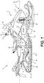
- a snowmobile 10 includes a forward end 12 and a rearward end 14 which are defined consistently with a forward travel direction.
- the snowmobile 10 has a frame 16 that includes a tunnel 18, an engine cradle portion 20 and a front suspension assembly portion 22.
- the tunnel 18, generally formed of sheet metal bent in an inverted U-shape, extends rearwardly along the longitudinal axis 61 of the snowmobile 10 and is connected at the front to the engine cradle portion 20.
- An engine 24, shown schematically in Figure 1 is carried by the engine cradle portion 20 of the frame 16.
- a fuel tank 25, supported above the tunnel 18, supplies fuel to the engine 24 for its operation.
- the front suspension assembly 28 includes ski legs 30, supporting arms 32 and ball joints (not shown) for operatively connecting the respective skis 26 to a steering column 34.
- An endless drive track 65 is positioned at the rear end 14 of the snowmobile 10.
- the drive track 65 is disposed generally under the tunnel 18, and is operatively connected to the engine 24 through a continuously variable transmission (CVT) 40 (illustrated schematically by broken lines in Fig. 1 ) and a drive sprocket (not shown).
- CVT continuously variable transmission
- the endless drive track 65 is driven to run about a rear suspension assembly 42 for propulsion of the snowmobile 10.
- the rear suspension assembly 42 includes a pair of slide rails 44 in sliding contact with the endless drive track 65.
- the rear suspension assembly 42 also includes one or more shock absorbers 46 and suspension arms 48 and 50 to attach the slide rails 44 to the frame 16.
- One or more idler wheels 52 are also provided in the rear suspension assembly 42.
- fairings 54 enclose the engine 24 and the CVT 40, thereby providing an external shell that protects the engine 24 and the CVT 40.
- the fairings 54 include a hood and one or more side panels which can be opened to allow access to the engine 24 and the CVT 40 when this is required, for example, for inspection or maintenance of the engine 24 and/or the CVT 40.
- a straddle-type seat 58 is positioned atop the fuel tank 25 and extends rearward from the fairings 54 to accommodate a driver of the snowmobile 10.
- a rear portion of the seat 58 may include a storage compartment or can be used to accommodate a passenger seat (not indicated).
- a footrest 60 is positioned on each side of the snowmobile 10 below the seat 58 to accommodate the driver's feet.
- the upper end of the steering column 34 is attached to a steering device such as a handlebar 36 which is positioned forward of the seat 58.
- the handlebar 36 is used to rotate the ski legs 30 and thus the skis 26, in order to steer the vehicle 10.
- a throttle operator 37 in the form of a finger-actuated throttle lever 37 is mounted near the left side grip of the handlebar 36.
- Other types of throttle operators such as a thumb-actuated throttle lever and a twist grip, are also contemplated.
- the throttle lever 37 is normally biased, typically by a spring, towards a position furthest away from the handlebar 36. This position of the throttle lever 37 is indicative of a desire for an idle operation of the engine 24 as will be described below.
- the throttle lever 37 can be pressed towards the handlebar 36 to increase air flow into the engine 24, and to thereby increase the output power of the engine 24 by means of a drive-by-wire (DBW) system.
- DWA drive-by-wire
- a throttle operator position PP is defined as a fraction of its fully activated position and thus varies between 0% (unactivated or idle position) and 100% (fully activated when throttle lever 37 is at its closest position to the handlebar 36). It is contemplated that the snowmobile 10 could not have a DBW system.
- a brake operator 38 in the form of a finger-actuated brake lever 38 is mounted near the right side grip of the handlebar 36.
- the brake lever 38 is connected to a brake disc (not shown) connected to the sprocket in order to brake the sprocket, and thereby the endless track 65 in a manner that will be understood by a worker skilled in the art.
- a display cluster 64 ( Figure 3 ) is provided in front of the handlebars 36 to display information, such as the vehicle speed, engine speed, vehicle mode, temperature and the like, to the driver of the snowmobile 10.
- the display cluster 64 possibly includes one or more gauges, display screens, indicator lights and sound output devices such as speakers, alarms and the like.
- a mode switch 62 ( Figure 3 ) is provided near or on the handlebar 62.
- the mode switch 62 is in the form of a toggle switch, but it is contemplated that it could be a push-button switch, knob, lever or other user control implemented into the display cluster 64 or gauges.
- the mode switch 62 has positions corresponding to an economy mode (ECO), a standard mode (STD) and a sport mode (SPORT), as will be described below in further detail.
- ECO economy mode
- STD standard mode
- SPORT sport mode
- the mode switch 62 can be toggled sequentially through the positions corresponding to the economy mode, the standard mode, and the sport mode.
- the driver of the snowmobile 10 indicates a desire to change the mode of operation from a current mode of operation CM to a desired mode of operation DM for the snowmobile 10 by actuating the mode switch 62 to the position corresponding to the desired mode DM.
- the modes of operation of the vehicle could be related to an authorization or identification of the driver, for example, as encoded in a key used to the start the vehicle 10.
- different keys could be associated with different modes, or each key could be authorized to operate the vehicle in one or more modes.
- the number and names of operation modes could be different than as described herein.
- the engine 24 is an internal combustion engine.
- the internal construction of the engine 24 may be of any known type and can operate on the two-stroke or four-stroke principle.
- the engine 24 drives a crankshaft 57 ( Figure 4A ) that rotates about a horizontally disposed axis 85 ( Figure 4A ) that extends generally transversely to the longitudinal axis 61 of the snowmobile 10.
- the crankshaft 57 drives the CVT 40, as described in greater detail below, for transmitting torque to the endless drive track 65 for propulsion of the snowmobile 10.
- FIG 2A illustrates schematically a powertrain 75 of the snowmobile 10.
- the powertrain 75 includes the engine 24, the CVT 40 and a fixed-ratio reduction drive 78.
- the CVT 40 includes a driving pulley 80 coupled directly to rotate with the crankshaft 57 of the engine 24 and a driven pulley 88 coupled to one end of a transversely mounted jackshaft 92 which is supported on the frame 16 by bearings. As illustrated, the transversely mounted jackshaft 92 traverses the width of the engine 24.
- the opposite end of the transversely mounted jackshaft 92 is connected to the input member of the reduction drive 78 and the output member of the reduction drive 78 is connected to a drive axle 90 carrying sprocket wheels (not shown) that form a driving connection with the drive track 65.
- the input member of the reduction drive 78 consists of a small sprocket connected to the transverse jackshaft 92 and coupled to drive an output member consisting of a larger sprocket connected to the drive axle 90 through a driving chain, all enclosed within the housing of the reduction drive 78.
- the driving pulley 80 rotates at the same speed ES as the crankshaft 57 of the engine 24 whereas the speed of rotation of the transverse jackshaft 92 is determined in accordance with the instantaneous ratio of the CVT 40.
- the drive axle 90 rotates at a lower speed than the transverse jackshaft 92 because of the action of the reduction drive 78.
- the driving pulley 80 could be coupled to an engine shaft other than the crankshaft 57, such as an output shaft, a counterbalance shaft, or a power take-off shaft driven by and extending from the engine 24.
- the driven pulley 88 could be coupled to a shaft other than the transverse jackshaft 92, such as directly to the drive axle 90 or any other shaft operatively connected to the ground engaging element of the vehicle (i.e. the drive track 65 in the case of the snowmobile 10).
- the driving pulley 80 of the CVT 40 includes a pair of opposed frusto-conical sheaves, 82 and 84, between which the endless belt member 86 is held.
- the driving pulley 80 will be described in greater detail below.
- the driven pulley 88 includes a pair of frusto-conical sheaves, 87 and 89, holding the endless belt member 86 between them.
- the gear ratio of the CVT 40 is defined as the ratio of the effective diameter D2 of the driven pulley 88 to the effective diameter D1 of the driving pulley 80.
- the effective diameters D1, D2 of the pulleys 80, 88 are determined by the radial position of the belt 86 held between the two sheaves, 82 and 84, 87 and 89, of the respective pulleys 80, 88.
- the radial position of the belt 86 held between two sheaves, 82 and 84, 87 and 89 changes with the separation between the sheaves, 82 and 84, 87 and 89. Since the length of the belt 86 remains constant, there is an inverse relationship between the effective diameters D1, D2 of the driving and driven pulleys 80, 88.
- the driving pulley sheaves 82, 84 are biased away from each other so that when not rotating, the driving pulley sheaves 82, 84 are far apart and the belt 86 is disengaged from the driving pulley 80.
- the moveable sheave moves in response to changes in engine speed ES.
- the effective diameters D1, D2 of the pulleys 80, 88 are in inverse relationship.
- the driving pulley sheaves 82, 84 engage the belt 86 which in turn begins to rotate the driven pulley sheaves 87, 89.
- the rotational speed ES (of the crankshaft 57 and driving pulley sheaves 82, 84) at which the driving pulley sheaves 82, 84 engage the belt 86 is referred to as the engagement speed ES engage .
- the engine 24 is operatively connected via the CVT 40 to the track 65.
- the CVT 40 is not engaged and thus the powertrain 75 cannot deliver torque and power from the engine 24 to the track 65.
- the snowmobile 10 is thus not being driven by the engine 24, and the engine 24 is in idle operation for engine speeds ES less than the engagement speed ES engage .
- Idle operation of the engine 24 enables powering of vehicle systems such as the displays 64, the ECU 200, and the like.
- the engine 24 can be placed in idle operation by releasing the throttle lever 37 without turning off the engine 24.
- the engine 24 is typically turned on and off by inserting a key (mechanical and/or electronic) into a key receiver or by the operation of an on/off switch.
- the engine 24 transmits torque via the crankshaft 57 to the driving pulley 80 to rotate the driving pulley 80.
- the separation between the driving pulley sheaves, 82 and 84, and the effective diameter of the driving pulley 80 is controlled by an adjusting mechanism that will be described in greater detail below.
- the belt 86 is engaged by the sheaves 82, 84 of the driving pulley 80 as described above.
- the belt 86 engages the driven pulley 88, rotating the sheaves, 87 and 89, changing the separation therebetween, and the effective diameter D2 of the driven pulley 88 as described above. Torque is thus transferred from the engine 24 to the driving pulley 80, the belt 86, the driven pulley 88 and finally to the drive axle 90.
- the driving pulley 80 rotates several times for each rotation of the driven pulley 88. This configuration is desirable in certain situations such as, for example, during acceleration of the snowmobile 10, where it is necessary to transfer a large torque to the driving pulley 88, and thereby to the drive axle 90.
- each rotation of the driving pulley 80 results in multiple rotations of the driven pulley 88. This is useful in certain situations, such as, for example, when the snowmobile 10 is being driven at constant and high speeds.
- the engine 24 is an inline, two-cylinder, four-stroke, internal combustion engine. It is however contemplated that the construction of the engine 24 may be of any known type.
- the engine 24 receives fuel from the fuel tank 25 via a fuel injection system 76 ( Figure 3 ).
- the engine 24 receives air from an air intake system 66 ( Figure 2B ) via a throttle body 68.
- the fuel-air mixture in the engine 24 is ignited by an ignition system 74.
- Engine output power P, torque ⁇ and engine speed ES are determined in part by the fuel-air mixture in the engine 24 and the ignition timing IT.
- the engine 24 is fluidly connected to a cooling system 284 for cooling the engine 24 during its operation.
- An engine control unit (ECU) 200 is operatively connected to the engine 24 to control operation of the engine 24 as will be discussed below.
- the throttle body 68 comprises a throttle valve 70 that regulates the amount of air flowing through the throttle body 68 into the engine 24.
- the throttle valve 70 is a butterfly valve comprising a circular disc mounted inside the tubular throttle body 68 that rotates about a rod passing through a diameter of the disc. The passage of air through the tubular throttle body 68 is obstructed by varying amounts as the disc rotates about the rod.
- the throttle valve 70 is in a fully open position (minimal obstruction of air flow) when the circular surface of the disc is at its minimum angle with respect to the central axis of the tubular throttle body 68, and in a fully closed position (maximal obstruction of air flow) when the circular surface of the disc is at its maximum angle with respect to the central axis of the tubular throttle body 68.
- a throttle valve actuator 72 in the form of an electric motor, is operatively connected to the throttle plate to change the position of the throttle plate and thereby adjust the opening of the throttle valve 70.
- a throttle valve position TVP can be defined in terms of a degree of opening of the throttle valve 70.
- the throttle valve position TVP is defined as a fraction of its fully open position and thus varies from 0% (fully closed) to 100% (fully open).
- a throttle valve sensor 206 is connected to the throttle valve 70 to sense the throttle valve position TVP.
- the throttle valve actuator 72 positions the throttle valve 70 based at least in part on a position PP of the throttle lever 37 of the snowmobile 10.
- the snowmobile 10 has a drive-by-wire (DBW) system in which the throttle valve 70 is controlled electronically instead of having a mechanical linkage between the throttle lever 37 and the throttle valve 70.
- the position PP of the throttle lever 37 is monitored by a throttle operator position sensor 204.
- the actuator 72 is controlled based in part on signals received from the ECU 200, as described below.
- the ECU 200 is in electronic communication with various sensors from which it receives signals.
- the ECU 200 uses these signals to control the operation of the throttle valve actuator 72, the ignition system 74, and the fuel injection system 76 in the case of a fuel injected engine, in order to control the engine 24.
- the methods by which the ECU 200 controls the engine 24 will be described in more detail below.
- the throttle operator position sensor 204 senses a position PP of the throttle operator 37 (finger or thumb actuated throttle lever 37 in the illustrated implementation of the snowmobile 10) and sends a signal representative of the throttle operator position PP to the ECU 200.
- the throttle operator position sensor 204 is generally disposed in proximity to the throttle operator 37 and senses the movement of the throttle operator 37 or the linear displacement of a cable connected to the throttle operator 37.
- the ECU 200 sends a signal to the throttle valve actuator 72 to adjust the position TVP, and thereby the opening, of the throttle valve 70 inside the throttle body 68.
- the throttle valve position TVP is adjusted based in part on the throttle operator position PP as well as on other factors such as the ignition timing IT, required output power P and torque ⁇ , the current mode of operation CM, and the like.
- the throttle valve position sensor 206 senses the position (i.e. the degree of opening) of the throttle valve 70 and sends a signal representative of the position TVP of the throttle valve 70 to the ECU 200.
- the throttle valve position sensor 206 acts as a feedback to the ECU 200 since the ECU 200 uses the signal received from the throttle valve position sensor 206 to determine if the throttle valve actuator 214 has moved the throttle valve 37 to the desired position and can make adjustments accordingly.
- the throttle valve position sensor 206 can be any suitable type of sensor such as a rheostat, hall-effect sensor, potentiometer, and the like.
- a separate throttle valve position sensor 206 may not be necessary.
- a separate throttle valve position sensor 206 would not be required if the throttle valve actuator 72 is a servo motor since servo motors integrate their own feedback circuit that corrects the position of the motor and thus have an integrated throttle valve position sensor 206.
- An engine speed sensor 208 senses a speed of rotation ES of the engine 24 and sends a signal representative of the speed of rotation ES of the engine 24 to the ECU 200.
- the engine speed sensor 208 is a hall-effect type sensor coupled to a trigger wheel on the engine output shaft. It is contemplated that the engine speed sensor 202 could be coupled to any rotating shaft of the engine 24, such as the crankshaft.
- the rotation speed ES of the engine 24 can be used by the ECU 200 to calculate the engine torque ⁇ and the power output P of the engine 24.
- a mode switch sensor 210 senses a position or a movement of the mode switch 62 and sends a signal to the ECU 200 indicative of the desired mode of operation DM (also referred to herein as the selected mode of operation of the vehicle).
- the mode switch sensor 210 is configured to sense a position of the mode switch 62 and the ECU 200 determines the corresponding desired mode of operation DM from the signal received from the mode switch sensor 210.
- the mode switch sensor 210 is configured to sense a movement of the mode switch 62, including the number of steps moved (one or two steps in the illustrated implementation) and a direction of movement ("up" or "down”). The mode switch sensor 210 sends a signal to the ECU 200 indicative of the movement and the ECU 200 determines the desired mode of operation DM based on the current mode of operation CM and the information received about the movement of the mode switch 62.
- a vehicle speed sensor 202 senses the speed VS of the snowmobile 10 and sends a signal representative of the speed VS of the snowmobile 10 to the cluster 64. It is contemplated that the vehicle speed sensor 202 could also send a signal representative of the speed VS of the snowmobile 10 to the ECU 200.
- the vehicle speed sensor 202 is a hall-effect sensor coupled to a trigger wheel on a driveshaft, such as the drive axle 90 so as to sense a rotational speed thereof. It is contemplated that the vehicle speed sensor 202 could sense a speed of any shaft driven by the driven pulley 88 (i.e. any shaft connected between the driven pulley 88 and the track 65), including shafts inside the reduction drive 78, to determine the speed of the snowmobile 10.
- vehicle speed sensor 202 could include a global positioning system (GPS unit). By using information from the GPS unit, the speed of the vehicle 10 can be determined by calculating a change in position of the vehicle 10 over a period of time which is normally a function of the GPS unit.
- GPS unit global positioning system
- a driven pulley speed sensor 203 senses the speed N 2 of the driven pulley 88 and sends a signal representative of the speed N 2 to the ECU 200.
- the driven pulley speed sensor 203 is a hall-effect sensor coupled to the jackshaft 92 so as to sense a rotational speed thereof.
- An altitude sensor 205 provided on the vehicle 10 determine the altitude at which the vehicle 10 is operating and sends a signal to the ECU.
- the altitude sensor in the illustrated implementation is an air pressure sensor (or barometer) that detects the atmospheric pressure in the vicinity of the vehicle 10 and determines the altitude based on the detected atmospheric pressure. It is contemplated that the sensor 205 is an altimeter. It is contemplated that the altitude sensor 205 could be part of the GPS unit mentioned above.
- An inclination sensor 280 is provided on the vehicle 10 to sense an inclination of the ground that the vehicle is operating on. It is contemplated that the inclination sensor 280 could be part of the GPS unit mentioned above.
- the ECU 200 is connected to the ignition system 74 to control ignition of the fuel-air mixture in the combustion chamber of the engine 24.
- the ECU 200 controls the ignition timing IT based partly on the throttle valve position TVP, the throttle operator position PP, and/or engine speed ES.
- the ECU 200 is also connected to the fuel injection system 76 to control fuel injection into the engine 24.
- the ECU is connected to an engine coolant temperature sensor 288 for monitoring the engine coolant temperature flowing through the engine cooling system 284, and thereby monitoring the operating temperature T E of the engine 24.
- the ECU 200 is connected to the display cluster 64 to control display of information thereon.
- the ECU 200 sends signals to the display cluster 64 to display information regarding engine and vehicle speed, and mode selection.
- ECU 200 could be separated into multiple units each having one or more of the functions described above and further below.
- the ECU 200 controls operation of the engine 24 based at least in part on the signals received from the sensors 202, 203, 204, 205, 206, 208, 210 and depending on the specific control scheme or map being used by the ECU 200.
- the control maps provide information related to various parameters (such as throttle valve position TVP, throttle operator position PP, fuel injection, ignition timing IT, engine torque, power output, etc.) needed for operation of the engine 24.
- a control map could provide information regarding the variation of throttle valve position and engine speed for achieving a particular power output or engine torque.
- the ECU 200 may also use algorithms, in addition to the control maps, to determine some of the parameters.
- the snowmobile 10 can be operated in different modes of operation (sport, standard and economy in the illustrated implementation) as mentioned above.
- Some of the control maps used by the ECU 200 are specific to each mode of operation and specify the variation of engine parameters for operation in that mode.
- the throttle response i.e. the throttle valve position TVP as a function of throttle operator position PP
- the throttle valve position TVP is defined as a fraction of its fully open position and thus varies from 0% (fully closed) to 100% (fully open).
- the throttle operator position PP is also defined as a fraction of its fully activated position and thus varies between 0% (unactivated or idle) and 100% (fully activated).
- the corresponding throttle valve position TVP for each mode increases from a minimum value for that mode to a maximum value for that mode.
- the minimum throttle valve position TVP corresponding to the 0% throttle operator position PP is greater than zero for all three modes. It is contemplated that the throttle valve position TVP corresponding to the 0% throttle operator position PP could be zero for all three modes.
- the minimum throttle valve position TVP corresponds to the idle throttle valve position ITVP for that mode and is set at a value greater than zero to enable idle operation in that mode.
- the corresponding economy mode throttle valve position TVP is lower than the corresponding sport and standard mode throttle valve positions TVP. Furthermore, for any given throttle operator position PP other than 100%, the sport mode throttle valve position TVP is greater than the corresponding standard mode throttle valve position TVP. At the 100% throttle operator position PP the sport and standard mode throttle valve positions TVP are equal.
- the maximum throttle valve position TVP in the sport and standard modes is set to be at its fully open position (i.e. at 100%), while in the economy mode, the maximum throttle valve position TVP is limited to 50% of its fully open position. It is contemplated that the maximum throttle valve position TVP of the standard mode could be less than that of the sport mode such that each of the three modes has a different maximum throttle valve position TVP. It is also contemplated that the maximum throttle valve position TVP of the standard mode could be the same as that of the economy mode. In the illustrated implementation, for each of the three modes, the maximum throttle valve position TVP is obtained when the throttle pedal 37 is positioned at its maximum throttle position PP of a 100%. It is contemplated that the maximum throttle valve position TVP could be obtained for a throttle operator position which is less than 100%.
- the engine 24 of the snowmobile 10 is capable of delivering a certain maximum output power based on its capacity as will be understood by a worker skilled in the art.
- the power P delivered by the engine 24 at any given instant is a function of, amongst other parameters, the throttle valve position TVP, the ignition timing IT and the fuel injection.
- the ECU 200 controls operation of the engine 24 such that the output power P delivered by the engine 24 also depends on the current mode of operation CM. For example, in the economy mode, the output power P delivered by the engine 24 is limited to a maximum value that is approximately 50% of the maximum output power available from the engine 24.
- the vehicle speed could be limited in one of the modes, for example, the vehicle speed could be limited in the economy mode, to increase fuel efficiency.
- the driving pulley 80 includes a pair of sheaves 82 and 84, both of which rotate together with the crankshaft 57 about a rotation axis 85 of the driving pulley 80.
- the inner and outer sheaves 82, 84 each have a belt-engaging surface 83.
- the belt 86 is held between the belt-engaging surface 83 of the driving sheaves 82, 84.
- the inner sheave 82, disposed between the outer sheave 84 and the engine 24, is fixed in the axial direction, and is therefore referred to as the fixed sheave 82.
- the outer sheave 84 can move toward or away from the fixed sheave 82 in the axial direction in order to change the drive ratio of the CVT 40, and is therefore referred to as the movable sheave 84. It is contemplated that both sheaves 82, 84 could be moveable in the axial direction.
- the sheaves 82, 84 of the driving pulley 80 are mounted on a driving shaft 100 which is rotationally coupled to the crankshaft 57.
- a portion 101 of the driving shaft 100 is taper-fitted on the end of the crankshaft 57.
- a bolt 102 is inserted into the driving shaft 100 from an end opposite the portion 101 and screwed into the end of the crankshaft 57 to retain the driving shaft 100 on the crankshaft 57.
- the driving shaft 100 could be rotationally coupled to the crankshaft 57 in other known manners.
- the driving shaft 100 could engage the crankshaft 57 via splines.
- the fixed sheave 82 is press-fit on the inner end of the driving shaft 100 so as to be axially fixed and to rotate therewith.
- the moveable sheave 84 is mounted on the driving shaft 100 axially outwards of the fixed sheave 82.
- the moveable sheave 84 is mounted on the driving shaft 100 on bearing sleeves 104 so as to be slidable in the axial direction.
- An annular spring chamber 110 coaxial with the driving shaft 100, is defined between the moveable sheave 84 and the driving shaft 100.
- a helical compression spring 116 is disposed inside the spring chamber 110, coaxial with the driving shaft 100.
- a flange 112 extending radially outwards from the outer surface of the driving shaft 100 into the spring chamber 110 forms a spring stop.
- the spring 116 is held in the spring chamber 110 between the axially fixed spring stop 112 and an axially moveable outer wall 114 formed by a portion of the moveable sheave 84. This arrangement of the spring 116 biases the movable sheave 84 away from the fixed sheave 82.
- the spring 116 could be held between a portion of the fixed sheave 82 and a portion of the moveable sheave 84, or an element fixedly connected to the slidably moveable sheave 84. It is also contemplated that the spring 116 could be held between a portion of the moveable sheave 84 and an axially fixed portion of the driving pulley 80, other than the flange 112, as long as the axially fixed portion is disposed axially inward of the portion of moveable sheave 84.
- centrifugal weights 120 are mounted on the outer surface of the moveable sheave 84.
- the centrifugal weights are in the form of flyweights or levers 120 having one end 121 attached to the outer surface of the moveable sheave 84, and the other end 122 being free to pivot away from the moveable sheave 84.
- flyweights or levers 120 When the moveable sheave 84 is at rest, the free end 122 of the centrifugal levers 120 rests against its outer surface. As the rotational speed of the moveable sheave 84 increases, the free end 122 pivots away from the moveable sheave 84 and radially outwards with respect to the driving shaft 100.
- a spider 90 and coverplate 92 are mounted on the driving shaft 100, axially outward of the moveable sheave 84, so as to rotate with the driving shaft 100.
- the coverplate 92 is fixed to the driving shaft 100 by the bolt 102 that retains the driving shaft 100 to the crankshaft 57.
- the spider 90 is fixed to the coverplate 92 by bolts inserted into holes 126 near its outer periphery. The spider 90 and the coverplate 92 thus rotate with the driving shaft 100.
- the spider 90 has a cylindrical hub 124 that extends coaxially around the driving shaft 100, and is spaced therefrom.
- the spider 90 has six pairs of flanges 128 extending inwards towards the moveable sheave 84.
- the six pairs of flanges 128 are radially distributed along the outer periphery.
- Each pair of flanges 128 has a roller 130 mounted rotatably between the ends thereof.
- Each roller 130 is in contact with a corresponding one of the centrifugal levers 120 of the moveable sheave 84.
- the flange pairs 128 also engage complementary flanges 129 of the moveable sheave 84 so that the moveable sheave 84 rotates with the spider 90, and therefore with the driving shaft 100, about the axis 85.
- Each complementary flange 129 of the moveable sheave 84 is received in the space between adjacent flange pairs 128 of the spider 90.
- the spider 90 is made of aluminum. It is contemplated that the spider 90 could be made of other suitable materials.
- the spider 90 has a plurality of apertures 140 formed radially outwards of the hub 124 and between the flange pairs 128. The apertures 140 serve to reduce weight. It is contemplated that the apertures 140 could be omitted.
- the coverplate 92 is made of aluminum. It is contemplated that the coverplate 92 could be made of other suitable materials.
- a plurality of cavities 138 are formed in the surface of the coverplate 92 facing away from the moveable sheave 84. The cavities 138 are formed for the purpose of the weight reduction. It is contemplated that the cavities 138 could be omitted.
- the fixed sheave 82 and the moveable sheave 84 of the driving pulley 80 are positioned as illustrated in Figure 4A .
- the sheaves 82, 84 are positioned as shown in Figure 4B .
- the centrifugal weights 120 which help to make this change in configuration, form part of the adjustment mechanism for adjusting the CVT gear ratio.
- centrifugal weights 120 could be attached to the spider 90 so as to be in contact with the moveable sheave 90, and to push the moveable sheave 84 away from the spider 90 with increasing rotational speed of the spider 90. It is also contemplated that the centrifugal weights could be in the form of roller weights that roll radially outwards with increasing rotational speed of the driving pulley 80. In such an implementation, surfaces in contact with the roller weights are sloped such that the roller weights can push the moveable sheave away from the spider 90.
- the compressed spring 116 exerts a force on the moveable sheave 84 to bias it away from the fixed sheave 82, i.e. in a direction opposite to the force exerted on the moveable sheave 84 due to the centrifugal weights 120.
- the balancing of these opposing forces partly determines the axial position of the moveable sheave 84.
- the centrifugal weights 120 form the mechanical part of the adjustment mechanism for the CVT gear ratio.
- a piston 94 is slidably mounted on the driving shaft 100, axially inwards of the coverplate 92, and inside the cylindrical hub 124 of the spider 90.
- the piston 94 is sealed against the outer surface of the driving shaft 100 by a seal 131 received in a groove formed in the inner cylindrical surface of the piston 94.
- the piston 94 is sealed against the inner surface of the cylindrical hub 124 by a seal 133 received in a groove formed in the outer cylindrical surface of the piston 94.
- the cylindrical hub 124 thus forms a cylinder for the piston 94.
- the cylindrical hub 124 will be referred to hereinafter as the cylinder 124.
- the piston 94 is moved away from the coverplate 92 by filling the space between the piston 94 and the coverplate 92 with pressurized air as will be described below.
- the stationary moveable sheave 84 i.e. moveable sheave 84 in its outermost axial position abuts the piston 94 when it is not actuated, as shown in the configuration of Figure 4A . It is contemplated that the stationary moveable sheave 84 could be spaced from the piston 94 in its unactuated configuration. It is also contemplated that the piston 94 could be attached to the moveable sheave 84, so as to slide and rotate with the moveable sheave 84. It is contemplated that the piston 94 could be disposed in a cylinder that does not form part of the spider 90. It is also contemplated that the piston 94 could have a different shape than as shown herein. It is contemplated that a plurality of pistons, with a corresponding number of cylinders, could be provided to apply force on the moveable sheave 84.
- a connector 96 mounted on the coverplate 92 connects an air conduit 98 to the interior of the cylinder 124 via air passages 93 formed in the coverplate 92.
- the connector 96 rotates with the coverplate 92 while the air conduit 98 is stationary. Bearings 137 are inserted between the stationary air conduit 98 and the connector 96.
- the connector 96 is rotatably sealed against the stationary air conduit 98 via lip seals 132.
- a higher engine RPM causes faster rotation of the driving pulley 80, increasing the force exerted on the moveable sheave 84 due to the centrifugal weights 120, resulting in a larger effective diameter for the driving pulley 80 (i.e. a smaller effective diameter for the driven pulley 88) and a lower gear ratio for the CVT 40.
- the gear ratio of the CVT is determined by the operation speed of the engine 24.
- the pneumatically actuated piston 94 modifies the response curve of the driving pulley 80.
- the driving pulley 80 achieves a larger effective diameter for a given engine RPM when the centrifugal weight mechanism is assisted by the pneumatically actuated piston 94 than when the pneumatic piston 94 is not actuated.
- the pneumatically actuated piston 94 effectively shifts the snowmobile 10 into a higher gear with a smaller engine RPM than would be possible with a CVT 40 controlled solely by mechanical means (i.e. centrifugal weights 120).
- the spring 116 returns the moveable sheave 84 to its initial position so that the CVT 40 returns to its purely mechanical characteristics with the effective diameter of the driving pulley 80, and thus the CVT gear ratio, being determined solely by the centrifugal weights 120.
- the CVT 40 is fully operational with and without the pneumatic piston 94 being actuated.
- the pneumatic piston 94 permits the CVT gear ratio to be controlled independently of the engine RPM.
- the CVT gear ratio can be adjusted based on consideration of factors such as, torque required by the drive axle 90, fuel consumption, driver comfort, or the like.
- the pneumatic pressure actuating the piston 94 can also be adjusted to achieve the response curve desired.
- the CVT 40 can be configured to maximize fuel economy, or performance, or to optimize both.
- the pneumatically actuated piston 94 can also be used to simulate the response of a multi-gear transmission.
- An electrical compressor 320 ( Figure 5 ) disposed elsewhere on the snowmobile 10 is used to provide pressurized air for actuating the piston 94.
- the compressor 320 includes an air-water separator to help prevent or minimize moisture inside the CVT 40. It is contemplated that a mechanical compressor could be used instead. It is contemplated that the compressor 320 could be any suitable compressor that is capable of achieving the requisite air pressure for actuation of the piston 94. It is also contemplated that the compressor 320 could be powered by an engine other than the engine 24, a motor or battery as appropriate.
- the air pressure applied to the piston 94 and the resultant piston force that fully converges the moveable and fixed sheaves 82, 84 toward each other is much smaller for the CVT 40 of the implementation illustrated in Figures 4A and 4B , than for a CVT in which the gear ratio is solely pneumatically controlled.
- the size of the pump or compressor 320 required to produce this piston force is much smaller than one required for a fully pneumatically-controlled CVT, resulting in energy and space savings for the snowmobile 10.
- An accumulator 322 ( Figure 5 ), serving as a reservoir of compressed air, is installed between the pump 220 and the cylinder 124 in order to ensure a short response time for actuation of the piston 94 under all operating conditions, and to limit pressure fluctuations.
- pressurized gas cartridges could be used instead of the compressor 320 and accumulator 322 to provide pressurized air for actuation of the piston 94.
- the actuation of the piston 94 is controlled automatically based on parameters such the vehicle speed, engine rotation speed (RPM), torque required, fuel reserve and the like. Different methods of controlling the CVT 40 have been described below.
- actuation of the piston 94 could additionally be controlled manually by the operator of the snowmobile 10.
- a switch such as a button switch, could be provided to switch the actuation on or off.
- a continuously adjustable knob could be provided to allow the driver of the snowmobile to set the amount of force being exerted by the piston 94.
- the pneumatic system 300 includes a compressor 320, an electric motor 340, an accumulator 322, a pressure regulation unit 328 including an air inlet valve 324, an air outlet valve 326, and a cylinder pressure sensor 330, and an accumulator pressure sensor 332.
- the PCU 310 regulates the pneumatic air pressure delivered to the piston 94 for selective and adjustable actuation of the piston 94.
- the cylinder 124 is connected to the compressor 320 for receiving pressurized air.
- the compressor 320 is operatively connected to the PCU 310.
- the PCU 310 sends electronic signals to the compressor 320 for activation thereof. It is contemplated that the PCU 310 could also be configured to receive signals from the compressor 320.
- an accumulator 322 in fluid communication with the compressor 320 (connected downstream of the compressor), stores compressed air for actuation of the piston 94 and helps to reduce the response time for actuation of the piston 94.
- the compressor 320 is connected to the cylinder 124 via the accumulator 322.
- Pressurized air flows from the compressor 320 to the accumulator 322, and from the accumulator 322 to the cylinder 124. It is contemplated that an additional air flow path could be provided for pressurized air to flow from the compressor 320 to the cylinder 124 without passing through the accumulator 322. It is contemplated that the accumulator 322 could be omitted.
- An air inlet valve 324 connected between the accumulator 322 and the cylinder 124 allows air flow from the accumulator 322 to the cylinder 124.
- the air inlet valve 324 is opened when the pressure inside the cylinder 124 (as determined by the cylinder pressure sensor 330) is less than desired, and if pressurized air at a higher pressure than that in the cylinder 124 is available from the accumulator 322 (as determined by the accumulator pressure sensor 332).
- An air outlet valve 326 connected to the cylinder 124 allows pressurized air in the cylinder 124 to be vented to the atmosphere.
- the air outlet valve 326 is opened if the pressure in the cylinder 124 is greater than desired.
- the air inlet valve 324 and the air outlet valve 326 are each operatively connected to the PCU 310.
- the valves 324, 326 can each be configured to open at particular pressure set-points.
- the pressure set-points for the valves 324, 326 can be assigned electronically or adjusted mechanically.
- the PCU 310 sends control signals to the valves 324, 326 to actuate their opening and closing. It is contemplated that the PCU 310 could also be configured to receive signals from the valves 324, 326. It is contemplated that the air inlet valve 324 and the air outlet valve 326 could be replaced with a single proportional relay valve.
- An accumulator pressure sensor 332 is connected to the accumulator 322 to measure the air pressure in the accumulator 322.
- the accumulator pressure sensor 332 is connected downstream of the accumulator 322, between the accumulator 322 and the air inlet valve 324. It is however contemplated that the accumulator pressure sensor 332 could be connected elsewhere on the accumulator 322.
- a cylinder air pressure sensor 330 measures the air pressure in the cylinder 124.
- the cylinder air pressure sensor 330 is shown connected between the air inlet valve 324 and the cylinder 124.
- the pressure sensors 330, 332 are each communicatively connected to the PCU 310.
- the PCU 310 is configured to receive data and/or signals from the pressure sensors 330, 332 indicative of the air pressure sensed by the pressure sensors 330, 332. It is contemplated that the PCU 310 could also be configured to send control or data signals to the pressure sensors 330, 332.
- the PCU 310 is further configured to send control signals to the air inlet valve 324, the air outlet valve 326, and the compressor 320 based in part on the signals received from the pressure sensors 330, 332.
- a pressurized gas cartridge could be used instead of the compressor 320 and accumulator 322.
- the PCU 310 would be operatively connected to the gas cartridge, and configured to send control or data signals thereto based on signals received from other sensors such as the cylinder pressure sensor 330.
- the PCU 310 is in communication with the ECU 200 for controlling operation of the piston 94. It is contemplated that some or all the functions of the PCU 310 could be integrated with the ECU 200.
- a piston force selector 380 is also provided.
- the piston force selector 380 is operable by the driver of the snowmobile 10 for actuating the piston and?or selecting a desired piston force Pf.
- the PCU 310 communicates with the piston force selector 380 for optionally controlling the piton force Pf based in part on the selected piston force.
- the piston force selector 380 could be in the form of a push-button, switch, knob, lever, or the like, that can be moved between a plurality of piston force selection positions, for example, 0, low and high.
- the centrifugal weights 120 of the CVT 40 are optimized for operating in the SPORT mode and at a high altitude (defined, in this implementation of the vehicle 10, as 2000 m above sea level and higher).
- a high altitude defined, in this implementation of the vehicle 10, as 2000 m above sea level and higher.
- the driving pulley diameter D1 is determined based on the engine speed ES, which is in turn controlled by the ECU 200 based on an engine speed control map (not shown) for the sport mode.
- the engine speed ES obtained for a given throttle valve position TVP and ignition timing IT is greater at low altitudes than at high altitudes due to the increased atmospheric air pressure at low altitudes.
- the higher atmospheric air pressure at low altitudes results in a greater amount of air being inducted through the throttle body into the combustion chamber for the same throttle valve opening TVP.
- a greater amount of fuel is injected to the engine 24 at low altitudes than at high altitudes which therefore produces more power, and rotates the crankshaft 57 at a higher engine speed ES for the same throttle valve opening TVP.
- the pneumatic piston 94 allows the engine speed ES to be controlled independently of the throttle valve position TVP.
- the pneumatic piston can be actuated to reduce the engine speed ES and thus compensate for this altitude related increase in engine speed ES.
- the method starts at step 410 where the PCU 310 determines the altitude based on the signal received from the altitude sensor.
- the PCU 310 determines the operation mode based on the signal received from the mode switch 62 or based on a key.
- step 430 determines whether the mode is SPORT and the altitude is at least as great as a high altitude threshold A HT ( i . e . the altitude is high), based on signals received from the mode switch sensor 210 and the altitude sensor 205 via the ECU 200.
- the high altitude threshold A HT is set to be 2000m, but it is contemplated that the high altitude threshold A HT could be other than 2000m.
- the mode is determined to be SPORT, and the altitude is determined to be high
- the method 400 proceeds to step 435 where the piston force Fp is set to be zero for all values of throttle operator position PP and driven pulley speed N 2 .
- the mode is determined to not be SPORT (i.e. mode is STD or ECO), or if the altitude is determined to be 2000m or less (i.e. the altitude is low), the method 400 proceeds to step 440.
- the PCU 310 determines the throttle operator position PP based on the signal received from the throttle position sensor 204 and then proceeds to step 450, where the PCU 310 determines the driven pulley speed N 2 based on the signal received from the driven pulley speed sensor 203. The method 400 then advances to step 460.
- the PCU 310 obtains the desired piston force Fp to be applied to the piston 94 from the appropriate piston force control map for the given mode and altitude. If the mode is SPORT and the altitude is low, the PCU 310 obtains piston force Fp from the SPORT MODE-LOW ALTITUDE control map ( Fig. 7 ). If the mode is STD and the altitude is low, the PCU 310 obtains piston force Fp from the STD MODE-LOW ALTITUDE control map ( Fig. 8B ). If the mode is STD and the altitude is high, the PCU 310 obtains piston force Fp from the STD MODE-HIGH ALTITUDE control map ( Fig 8A ).
- the PCU 310 For ECO mode and low altitude, the PCU 310 obtains piston force Fp from the ECO MODE-LOW ALTITUDE control map ( Fig 9B ), and for ECO mode and high altitude, the PCU 310 obtains piston force Fp from the ECO MODE-HIGH ALTITUDE control map ( Fig. 9A ).
- the PCU 310 adjusts the pneumatic pressure P in the cylinder 144 based on the desired piston force Fp obtained from the relevant control map in step 470.
- the PCU 310 receives signals from the pressure sensors 330, 332 and sends signals to the compressor 340, and the valves 324, 326 to adjust the pneumatic pressure to the desired value.
- the PCU 310 uses the high altitude control map for any altitude greater than or equal to the high altitude threshold A HT , and the sea level control map for altitudes of lower than the high altitude threshold A HT . It is contemplated that, for intermediate altitudes between high altitude threshold A HT and sea level, the PCU 310 could interpolate between the high altitude and sea level control maps for the given mode. It is contemplated that more than two control maps could be used for altitude compensation, for example, an additional control map could be provided for intermediate altitudes between the high altitude threshold A HT and sea level.
- a low altitude threshold A LT could be defined, a low altitude control map could be used for altitudes up to the low altitude threshold A LT , and an intermediate altitude control map could be used for altitudes between the low altitude threshold A LT and high altitude threshold A HT . It is contemplated that a control map could also be provided for altitudes below sea level.
- the piston 94 applies a force Fp on the moveable sheave 84 of the driving pulley 80 based on the throttle operator position PP and the driven pulley speed N 2 (which is related to the vehicle speed VS in a known manner). It is contemplated that the piston force Pf could be determined based on the throttle valve position TVP instead of the throttle operator position PP.
- Fig. 7 shows a piston force control map 700 for low altitudes and in sport mode.
- a piston force Pf is exerted when the throttle operator position PP is greater than a minimum threshold PP2 (about 20% in this implementation) or when the driven pulley speed N 2 exceeds a threshold N2a (about 5000rpm in this implementation).
- the piston force Pf increases with increasing throttle operator position PP up to a maximum (in the illustrated implementation, the maximum piston force Pf is exerted at about 75% throttle operator position PP). Thereafter the piston force Pf decreases with increasing throttle operator position PP.
- a piston force Pf is not applied when the driven pulley speed N 2 is zero unless the throttle operator position PP exceeds a threshold PP1 (about 60% in the illustrated implementation).
- the PCU 310 applies a small but non-zero piston force Pf.
- the piston force Fp generally increases with driven pulley speed N 2 , up to a maximum piston force Fp and then decreases with increasing driven pulley speed N 2 .
- the piston 94 when operating in the STD mode at high altitude, applies a force Fp on the driving pulley sheave 84 so as to lower the gear ratio (D1/D2) and obtain a lower engine speed ES for a given vehicle speed VS as compared to SPORT mode.
- the piston force Fp applied is non-zero only when the throttle operator position PP exceeds a given minimum (20% in the illustrated implementation) and when the driven pulley speed N 2 is below a maximum (8000 rpm in the illustrated implementation).
- the piston force Fp is highest for intermediate values of driven pulley speed (approximately 5000rpm in the illustrated implementation).
- the piston force Fp on the driving pulley sheave 84 is larger compared to the standard mode piston force at high altitude, as well as the sport mode sea level piston force .
- the piston 94 when operating in the ECO mode at high altitude, the piston 94 generally applies a greater force Fp on the driving pulley sheave 84 than in the standard mode at high altitude so as to further lower the gear ratio (D1/D2) compared to the standard mode at high altitude.
- the piston force Fp in the economy mode at high altitude is however not as high as the piston force Fp applied in the standard mode at sea level ( Fig. 9B ). In the economy mode at sea level, the piston force Fp is non-zero for all values of driven pulley speed N 2 .
- the piston force Fp applied is non-zero only when the throttle operator position PP exceeds a given minimum (20% in the illustrated implementation which is the same as in the standard mode).
- the piston force Fp is highest for intermediate values of driven pulley speed (approximately 5000rpm in the illustrated implementation).
- the piston 94 force Fp on the driving pulley sheave 84 is increased compared to the economy mode high altitude piston force Fp as well as the standard mode sea level piston force Fp.
- the piston force Fp is increased in order to compensate for the increased engine speed ES due to the increase in air pressure.
- control maps 700, 800, 800', 900, 900' discussed above for controlling the piston force Pf could correspond to different air pressures instead of different altitudes.
- the PCU 310 could also be connected to the ECU 200 and /or other sensors such as the engine speed sensor 208, in a closed loop feedback control for adjusting the piston force Pf to achieve a target engine speed ES.
- Fig. 10 a parking or drive-away control function of the PCU 310 will be described in detail.
- the engine 24 When the vehicle 10 is started, the engine 24 has to be revved up so as to increase the engine speed ES beyond the engagement speed ES engage in order to engage the CVT 40.
- the driver presses on the throttle lever 37 to increase the throttle operator position PP and to thereby increase the throttle valve opening TVP and increase the engine speed ES.
- the revving up of the engine 24 in this manner typically generates considerable noise in addition to increased fuel consumption.
- the CVT 40 is pneumatically controlled using the control map 1000 in order to enable a smoother start-up of the vehicle 10 with reduced noise and fuel consumption.
- the CVT 40 is also pneumatically controlled when the vehicle 10 is moving at a low vehicle speed VS and when the engine 24 is operating at a low engine speed ES.
- the PCU 310 increases the piston force Fp on the sheave 84 so that the vehicle speed VS can increase without requiring as much of an increase in the engine speed ES as would be needed in the absence of the pneumatic system 300. This relative reduction of engine speed ES also leads to less noise and fuel consumption.
- the parking function piston force Pf increases with the throttle operator position PP, with the rate of increase being higher for throttle operator positions PP below a threshold throttle operator position PP9 (10% in the illustrated implementation).
- the threshold throttle operator position PP9 is generally set to be at the level where the vehicle 10 starts moving. In the region 1010 of the control map 1000, (PP ⁇ PP9), the vehicle 10 has not yet started moving while in the region 1020 (PP>PP9), the vehicle 10 is moving at slow speeds VS and the engine 24 is operating at low engine speeds ES).
- a parking function piston force Pf is applied for throttle operator positions PP up to 50% and the maximum parking function piston force Pf applied is approximately 700N (in this implementation, where a total force of about 2000N is needed to increase the driving pulley diameter to its maximum value.
- the piston force Fp applied to the CVT 40 is also dependent on the engine temperature T E . If the engine 24 is already warm when the vehicle 10 is started, for example, if the engine 24 is started up shortly after having been shut down, the piston force Pf applied is such that the engagement speed reduction is slightly greater than if the engine 24 were started from cold. When the engine 24 is cold, it is desirable to warm up the engine 24 by allowing it to operate at slightly higher speeds. Therefore, the force applied by the piston 94 is higher for higher engine temperatures T E .
- the temperature dependence of the piston force Pf is influenced by a number of parameters, including those related to the pneumatic system, such as friction, thermal expansion, and the like. It is also contemplated that a the piston force Pf applied could be lower at higher temperatures.
- the piston force Pf is also based on the mode of operation.
- the CVT 40 In the sport mode, the CVT 40 is operated purely mechanically without applying any piston force Pf in order to obtain a large torque and enable the vehicle 10 to accelerate faster.
- a non-zero piston force Pf is applied in the STD and ECO modes.
- the piston force Pf is the same in the STD and ECO modes.
- the control map 1000 shown in Fig. 10 is used in both of the STD and ECO modes. It is however contemplated that different piston force control maps could be used in the STD and ECO modes to apply different piston forces. For example, for a given throttle operator position PP, the piston force Pf could be greater in the ECO mode than in the STD mode.
- the PCU 310 causes application of a parking function piston force when it determines a parking/drive-away condition that is indicative of the vehicle 10 being in the process of parking or driving away from a parked position.
- the PCU 310 determines a parking/drive-away condition if the vehicle speed VS is smaller than a parking start threshold vehicle speed VS P1 , and the engine speed ES is lower than a parking threshold engine speed ES P1 .
- the parking threshold engine speed ES P1 is set to 1500 rpm in the illustrated implementation.
- the parking/drive-away conditions include the brake 38 not being actuated.
- the PCU 310 accesses the parking control map of Fig. 10 to adjust the pneumatic pressure P in order to create the piston force Pf obtained from the parking piston force control map 1000. If the vehicle 10 is in a SPORT mode and if the pneumatic pressure is at a non-zero level, the PCU 310 releases to the pneumatic pressure to ensure that the CVT is only mechanically controlled. Typically, however, the pneumatic pressure P and the piston force Pf are zero when the vehicle 10 is started. If a closed loop feedback control is being used for adjusting of the piston force Pf, it is deactivated when the parking function piston force is applied.
- a piston force Pf could be applied even if the vehicle 10 is operating in a SPORT mode and the parking/drive-away conditions are detected. Therefore, in some implementations, a parking force control map could be provided for the SPORT mode as well.
- the parking function piston force Pf is removed when the PCU 310 determines that the vehicle 10 has started moving (i.e., when the vehicle speed increases above a parking end threshold vehicle speed, VS P2 ).
- the parking end threshold vehicle speed VS P2 is greater than the parking start threshold vehicle speed VS P1 . It is however contemplated that the parking start threshold vehicle speed VS P1 could be the same as the parking end threshold vehicle speed VS P2 .
- the vehicle 10 is considered to be moving and the parking function piston force Pf is removed when vehicle speed VS increases above the parking end threshold vehicle speed VS P2 (which is set to be at 10 km/h in the illustrated implementation), and when the engine speed ES is greater than a parking threshold engine speed ES P2 (set to be at 2200rpm for the ECO mode in the illustrated implementation).
- the parking threshold engine speed ES P2 is greater for the STD mode than for the ECO mode.
- the PCU 310 also stops application of the parking function piston force Pf if the PCU 310 determines that the engine speed ES is close to an engine stall speed ES stall which is different for different modes, and is generally lower than the idle engine speed ES idle for that mode. Additionally, if the brake 38 is determined to be actuated, the PCU 310 stops application of the parking function piston force Pf.
- Figs. 11A and 11B a minimum force control of the CVT 40 will be described in detail.
- the driver When a vehicle 10 is moving downhill, the driver sometimes releases the throttle operator 37 or holds the throttle operator 37 at a low position (i.e. PP ⁇ 0%) since the vehicle 10 is being accelerated due to gravity.
- the ECU 200 therefore decreases the throttle valve position TVP in accordance with the throttle operator position PP.
- the engine speed ES could decrease to almost zero and could cause the belt 86 of the CVT to disengage from the driving pulley 82 while the vehicle 10 continues to roll downhill.
- the PCU 310 controls the piston force Pf to be at least as great as a minimum piston force Pfmin to keep the CVT 40 engaged.
- the vehicle speed VS and therefore driven pulley speed N2 is greater than the driving pulley speed N 1 and the engine speed ES.
- the driven pulley 88 drives the driving pulley 80 and the engine output shaft 57.
- the rotational speed ES of the engine crankshaft 57 driven by the driven pulley 88 is greater than that would be achieved if the crankshaft 57 were being driven by the engine 24 based on the low throttle valve position TVP.
- the minimum piston force Pfmin is defined based on the engine speed ES, the engine temperature T E , and the mode of operation as can be seen from the maps 1100 and 1100' of Figs 11A and 11B .
- the PCU 310 accesses the control map 1100 in the STD mode and the control map 1100' in the ECO mode to obtain the piston force Pf to be applied to the driving pulley 80.
- the PCU 310 sets the piston force Pf to be zero.
- the CVT 40 is controlled purely mechanically in the SPORT mode. It is contemplated that a minimum piston force could also be defined for the SPORT mode.
- the minimum piston force control of the CVT 40 is activated when the PCU 310 determines that the engine speed ES is above a threshold speed ES11.
- the PCU 310 stops applying the piston force Pf from the downhill minimum force control map 1100, 1100' if the engine speed ES decreases below the threshold speed ES11, or if the driver switches the operation mode from STD and ECO modes to the SPORT mode.
- the minimum piston force control could be activated when a negative load condition is detected, i.e. when the engine speed ES is greater than a downhill threshold engine speed and at least one of the following is true: the throttle operation position PP is lower than a downhill threshold throttle operation position, and the throttle valve position TVP is lower than a downhill threshold throttle valve position.
- the PCU 310 also controls the pneumatic piston 94 in order to prevent stalling of the engine 24 as will be described below.
- the engine 24 can stall, for example, if the throttle operator 37 is suddenly released and the brake 38 actuated, causing the throttle valve TVP to be closed by the ECU 200.
- Another example of a situation where the engine 24 could stall is when the brake 38 is actuated while the ground engaging member of the vehicle 10, whether it be wheels or the track 65, is not in contact with ground.
- the PCU 310 causes the pneumatic valve 326 to be opened, thereby venting the pressure P on the piston 94, and quickly deactuating the piston 94.
- the CVT 40 disengages, thereby isolating the engine 24 from the suddenly braking wheels.
- the engine 24 would continue operating at low engine speeds less than ES engage , so that when the driver releases the brake 38 and begins actuating the throttle operator 37, the engine speed ES can be quickly increased in response to the throttle operator position PP.
- the stall protection control of the CVT 40 by the PCU 310 is activated when the PCU 310 detects a stall condition.
- the stall condition includes a high negative rate of change of the driven pulley speed N 2 .
- the rate of change of the driven pulley speed is determined to be high when the magnitude of the rate of change is than greater than a stall threshold rate, which is set to be 150 rpm/s 2 . It is however contemplated that the stall threshold rate could be different than 150 rpm/s 2 . It is also contemplated that the stall protection control could be activated if the brake 38 is actuated when a high negative rate of change of the driven pulley speed N 2 occurs.
- the pneumatic piston 94 is controlled by the PCU 310 to enable a smooth start from a temporary stop on an uphill gradient.
- the PCU 310 detects an opposite direction of rotation of the driven pulley 88 (negative driven pulley speed N 2 )
- the PCU 310 determines that the vehicle 10 is positioned on an incline and facing uphill uphill stand condition ).
- the detection of the uphill stand condition could also be based in part on the inclination of the ground as determined by the acceleration sensor 205 or the inclination sensor 280 provided on the vehicle 10.
- the PCU 310 increases the piston force Fp at a defined rate ( ⁇ 2000N/s in the illustrated implementation).
- the PCU 310 continues to increase the piston force Pf either until the driven pulley speed N 2 is detected to be zero, or up to a pre-defined maximum piston force Fp (700N in the illustrated implementation).
- the piston force Pf is increased at a rate such that the piston force Pf reaches the maximum piston force within an uphill stand threshold time period.
- the uphill stand threshold time period is 1 second.
- the piston force Pf is maintained at the level at which driven pulley speed N 2 is detected to be zero. Once the piston force Pf increases to the pre-defined maximum level for the uphill stand condition control, the piston force Pf is maintained at that level.
- the uphill stand pneumatic control of the CVT 40 ends when the throttle operator 37 is actuated by the driver, i.e. when throttle operator position PP is non-zero, PP>0 or when the brake 38 is actuated, at which point, the piston force Fp is returned to its default value (i.e. the value based on its mode of operation, engine speed ES and other operational parameters).
Claims (8)
- Procédé de fonctionnement d'un véhicule,le véhicule comprenant :un moteur ;une pédale d'accélération pouvant être déplacée par un conducteur du véhicule ;un papillon des gaz régulant le flux d'air vers le moteur, une position du papillon des gaz étant basée au moins en partie sur la position de la pédale d'accélération ;une transmission à variation continue (TVC) fonctionnellement reliée au moteur, la TVC comprenant une poulie d'entraînement, une poulie entraînée et une courroie reliant fonctionnellement la poulie d'entraînement à la poulie entraînée ;au moins un élément de contact avec le sol relié fonctionnellement à la poulie entraînée et comprenant au moins l'une parmi : une roue et une chenille ;un piston relié fonctionnellement à la poulie d'entraînement pour appliquer une force de piston à la poulie d'entraînement lorsqu'il est actionné et changer ainsi un diamètre effectif de la poulie d'entraînement ; etune unité de commande pour commander l'actionnement du piston et la force de piston,le procédé comprenant :la détermination d'une vitesse de poulie entraînée de la poulie entraînée ;la détection d'une condition d'arrêt en montée indiquant que le véhicule est arrêté dans une montée ; eten réponse à la détection de la condition d'arrêt en montée, la commande de la force du piston sur la base de la vitesse de poulie entraînée.
- Procédé selon la revendication 1, dans lequel le véhicule comprend en outre un frein relié fonctionnellement à l'au moins un élément de contact avec le sol,
la condition d'arrêt en montée comprenant :un actionnement du frein suivi d'un désactionnement du frein ; etau moins l'une parmi :la position de la pédale d'accélération étant inférieure à un seuil de pédale d'accélération d'arrêt en montée ; etla position du papillon des gaz étant inférieure à un seuil du papillon des gaz d'arrêt en montée. - Procédé selon la revendication 2, comprenant en outre la détection d'une inclinaison du sol ; et dans lequel la condition d'arrêt en montée comprend en outre l'inclinaison détectée qui est en montée.
- Procédé selon la revendication 1, dans lequel la commande de la force de piston comprend :
en réponse au fait que la vitesse de poulie entraînée est négative, l'augmentation de la force de piston jusqu'à ce qu'au moins l'un des événements suivants se produise :la vitesse de poulie entraînée devient nulle ; etla force de piston devient égale à une force de piston maximale. - Procédé selon la revendication 4, dans lequel la commande de la force de piston comprend :
l'augmentation de la force de piston à une vitesse telle que la force de piston augmente jusqu'à la force de piston maximale au cours d'un délai seuil d'arrêt en montée. - Procédé selon la revendication 5, dans lequel le délai seuil d'arrêt en montée est d'une seconde.
- Procédé selon l'une quelconque des revendications 1 à 6, dans lequel le piston est au moins l'un parmi : actionné pneumatiquement et actionné hydrauliquement.
- Procédé selon la revendication 1, comprenant en outre :la détermination d'une vitesse de moteur ; etle réglage de la force de piston pour qu'elle soit au moins aussi grande qu'une force de piston minimale, la force de piston minimale étant prédéfinie sur la base de la vitesse de moteur déterminée.
Applications Claiming Priority (3)
| Application Number | Priority Date | Filing Date | Title |
|---|---|---|---|
| US201461934498P | 2014-01-31 | 2014-01-31 | |
| PCT/IB2015/050797 WO2015114603A2 (fr) | 2014-01-31 | 2015-02-02 | Transmission à variation continue et procédés de commande de véhicule |
| EP15703633.6A EP3099961B1 (fr) | 2014-01-31 | 2015-02-02 | Transmission à variation continue et procédés de commande de véhicule |
Related Parent Applications (2)
| Application Number | Title | Priority Date | Filing Date |
|---|---|---|---|
| EP15703633.6A Division-Into EP3099961B1 (fr) | 2014-01-31 | 2015-02-02 | Transmission à variation continue et procédés de commande de véhicule |
| EP15703633.6A Division EP3099961B1 (fr) | 2014-01-31 | 2015-02-02 | Transmission à variation continue et procédés de commande de véhicule |
Publications (2)
| Publication Number | Publication Date |
|---|---|
| EP3751181A1 EP3751181A1 (fr) | 2020-12-16 |
| EP3751181B1 true EP3751181B1 (fr) | 2022-01-12 |
Family
ID=52464434
Family Applications (2)
| Application Number | Title | Priority Date | Filing Date |
|---|---|---|---|
| EP15703633.6A Active EP3099961B1 (fr) | 2014-01-31 | 2015-02-02 | Transmission à variation continue et procédés de commande de véhicule |
| EP20177734.9A Active EP3751181B1 (fr) | 2014-01-31 | 2015-02-02 | Procédé de fonctionnement d'un véhicule |
Family Applications Before (1)
| Application Number | Title | Priority Date | Filing Date |
|---|---|---|---|
| EP15703633.6A Active EP3099961B1 (fr) | 2014-01-31 | 2015-02-02 | Transmission à variation continue et procédés de commande de véhicule |
Country Status (6)
| Country | Link |
|---|---|
| US (4) | US10670144B2 (fr) |
| EP (2) | EP3099961B1 (fr) |
| CN (1) | CN106104090A (fr) |
| CA (1) | CA2937209A1 (fr) |
| RU (1) | RU2680209C2 (fr) |
| WO (1) | WO2015114603A2 (fr) |
Families Citing this family (6)
| Publication number | Priority date | Publication date | Assignee | Title |
|---|---|---|---|---|
| US10822054B2 (en) * | 2014-02-25 | 2020-11-03 | Bombardier Recreational Products Inc. | Side panel for a vehicle |
| WO2017072743A1 (fr) * | 2015-10-30 | 2017-05-04 | Bombardier Recreational Products Inc. | Poulie d'entraînement de transmission à variation continue |
| DE102015224840A1 (de) * | 2015-12-10 | 2017-06-14 | Robert Bosch Gmbh | Pneumatisch verstellbares CVT-Getriebe sowie Verfahren zur Verstellung eines CVT-Getriebes |
| WO2018118128A1 (fr) * | 2016-12-22 | 2018-06-28 | Eaton Corporation | Transmission à haut rendement et à efficacité élevée |
| US10428938B2 (en) * | 2017-07-21 | 2019-10-01 | GM Global Technology Operations LLC | Method and system for controlling a vehicle propulsion system |
| CN108825773B (zh) * | 2018-05-18 | 2019-07-05 | 吉林大学 | 一种带有副箱结构的金属带式无级变速器目标挡位与带轮目标速比决策方法 |
Family Cites Families (31)
| Publication number | Priority date | Publication date | Assignee | Title |
|---|---|---|---|---|
| ES256110A1 (es) | 1959-03-21 | 1960-08-16 | Doorne S Automobielfabriek N V | Un vehiculo de motor |
| JPS6098253A (ja) * | 1983-10-31 | 1985-06-01 | Mazda Motor Corp | 無段変速機の制御方法 |
| US4893526A (en) | 1986-09-19 | 1990-01-16 | Toyota Jidosha Kabushiki Kaisha | Continuous variable transmission control system |
| JPH02163563A (ja) * | 1988-12-14 | 1990-06-22 | Fuji Heavy Ind Ltd | 無段変速機の油圧制御装置 |
| JP2863932B2 (ja) * | 1989-09-30 | 1999-03-03 | スズキ株式会社 | 連続可変変速機制御装置 |
| JPH05180302A (ja) * | 1991-12-26 | 1993-07-20 | Toyota Motor Corp | 副変速機およびベルト式無段変速機を備えた車両の後退防止装置 |
| JP3300159B2 (ja) * | 1994-05-27 | 2002-07-08 | 富士重工業株式会社 | 無段変速機の制御装置 |
| JP3001859B1 (ja) * | 1998-08-18 | 2000-01-24 | 本田技研工業株式会社 | 車両用無段変速機の変速制御装置 |
| JP2001241540A (ja) | 1999-12-24 | 2001-09-07 | Aisin Aw Co Ltd | 自動変速機制御装置、自動変速機制御方法及びそのプログラムを記録した記録媒体 |
| JP4228513B2 (ja) * | 2000-04-17 | 2009-02-25 | トヨタ自動車株式会社 | 車両用無段変速機の制御装置 |
| JP2004124959A (ja) | 2002-09-30 | 2004-04-22 | Jatco Ltd | 自動変速機の制御装置 |
| JP2005036820A (ja) * | 2003-07-15 | 2005-02-10 | Nissan Motor Co Ltd | アイドルストップ車両の変速機油圧制御装置 |
| JP4238906B2 (ja) * | 2006-10-13 | 2009-03-18 | トヨタ自動車株式会社 | 無段変速機の制御装置、制御方法、その方法を実現させるプログラムおよびそのプログラムを記録した記録媒体 |
| JP4386095B2 (ja) * | 2007-04-12 | 2009-12-16 | トヨタ自動車株式会社 | 無段変速機の制御装置、制御方法およびその方法をコンピュータに実行させるプログラムならびにそのプログラムを記録した記録媒体 |
| JP4678036B2 (ja) * | 2008-04-16 | 2011-04-27 | トヨタ自動車株式会社 | 車両用無段変速機の制御装置および制御プログラム |
| JP4613226B2 (ja) * | 2008-05-30 | 2011-01-12 | ジヤトコ株式会社 | 無段変速機の制御装置 |
| JP5326805B2 (ja) * | 2008-07-31 | 2013-10-30 | 日産自動車株式会社 | アクセルペダル踏力制御装置 |
| JP5123864B2 (ja) * | 2009-01-09 | 2013-01-23 | 本田技研工業株式会社 | ベルト式無段変速機の制御装置 |
| JP4525832B1 (ja) * | 2009-04-15 | 2010-08-18 | トヨタ自動車株式会社 | 車両用無段変速機の制御装置 |
| ES2763434T3 (es) | 2010-12-23 | 2020-05-28 | Consortium De Recherche Brp Univ De Sherbrooke S E N C | Método de control de embrague de vehículo |
| US9487213B2 (en) * | 2011-02-01 | 2016-11-08 | Toyota Jidosha Kabushiki Kaisha | Vehicle control device |
| CA2830523A1 (fr) * | 2011-03-22 | 2012-09-27 | Bombardier Recreational Products Inc. | Poulie motrice de transmission a variation continue |
| JP5790173B2 (ja) * | 2011-06-07 | 2015-10-07 | トヨタ自動車株式会社 | 車両用無段変速機の制御装置 |
| JP5395853B2 (ja) * | 2011-08-10 | 2014-01-22 | 本田技研工業株式会社 | 自動変速機の制御装置 |
| CN103459897B (zh) * | 2012-03-21 | 2014-11-05 | 本田技研工业株式会社 | 自动变速机构的控制装置 |
| JP5740336B2 (ja) * | 2012-03-28 | 2015-06-24 | ジヤトコ株式会社 | 無段変速機の変速制御装置 |
| CA2886623A1 (fr) * | 2012-09-28 | 2014-04-03 | Brp-Powertrain Gmbh & Co. Kg | Transmission a variation continue a assistance pneumatique |
| US9945479B2 (en) * | 2013-01-30 | 2018-04-17 | Brp-Rotax Gmbh & Co. Kg | Method of operating a vehicle and a vehicle |
| EP3061995B8 (fr) | 2013-10-24 | 2018-03-21 | Jatco Ltd | Dispositif de commande de pression d'huile pour transmission variable en continu du type à courroie |
| KR101796408B1 (ko) * | 2013-12-11 | 2017-11-09 | 쟈트코 가부시키가이샤 | 무단 변속기의 제어 장치 |
| US9151382B2 (en) | 2014-02-24 | 2015-10-06 | GM Global Technology Operations LLC | Gross slip-based control of a variator assembly |
-
2015
- 2015-02-02 EP EP15703633.6A patent/EP3099961B1/fr active Active
- 2015-02-02 WO PCT/IB2015/050797 patent/WO2015114603A2/fr active Application Filing
- 2015-02-02 CN CN201580008217.XA patent/CN106104090A/zh not_active Withdrawn
- 2015-02-02 EP EP20177734.9A patent/EP3751181B1/fr active Active
- 2015-02-02 CA CA2937209A patent/CA2937209A1/fr not_active Abandoned
- 2015-02-02 RU RU2016134025A patent/RU2680209C2/ru active
-
2018
- 2018-03-06 US US15/913,006 patent/US10670144B2/en active Active
- 2018-03-06 US US15/912,992 patent/US10711889B2/en active Active
-
2020
- 2020-06-02 US US16/890,072 patent/US11261963B2/en active Active
-
2022
- 2022-02-04 US US17/592,897 patent/US11794843B2/en active Active
Also Published As
| Publication number | Publication date |
|---|---|
| EP3099961A2 (fr) | 2016-12-07 |
| RU2016134025A (ru) | 2018-03-05 |
| RU2680209C2 (ru) | 2019-02-18 |
| US20220153378A1 (en) | 2022-05-19 |
| WO2015114603A3 (fr) | 2015-09-24 |
| US20180195607A1 (en) | 2018-07-12 |
| US10670144B2 (en) | 2020-06-02 |
| WO2015114603A2 (fr) | 2015-08-06 |
| US20200292073A1 (en) | 2020-09-17 |
| US20180195606A1 (en) | 2018-07-12 |
| RU2016134025A3 (fr) | 2018-10-30 |
| EP3099961B1 (fr) | 2020-08-26 |
| EP3751181A1 (fr) | 2020-12-16 |
| CA2937209A1 (fr) | 2015-08-06 |
| CN106104090A (zh) | 2016-11-09 |
| US10711889B2 (en) | 2020-07-14 |
| US11794843B2 (en) | 2023-10-24 |
| US11261963B2 (en) | 2022-03-01 |
Similar Documents
| Publication | Publication Date | Title |
|---|---|---|
| US11794843B2 (en) | Method of operating a vehicle and a vehicle | |
| US9945479B2 (en) | Method of operating a vehicle and a vehicle | |
| US9476486B2 (en) | Pneumatically assisted continuously variable transmission | |
| US8755980B2 (en) | Vehicle and control device and control method thereof | |
| EP2478258B1 (fr) | Poulie d'entraînement pour transmission à variation continue | |
| EP1972836B1 (fr) | Variateur continu de vitesse commandé électroniquement | |
| US10774766B2 (en) | Method for engine braking a vehicle having a continuously variable transmission | |
| US9481370B2 (en) | Methods and system for operation of vehicle | |
| EP2478273A1 (fr) | Groupe propulseur de véhicule à transmission hydraulique à variation continue | |
| RU2782720C1 (ru) | Способ управления трансмиссией транспортного средства и транспортное средство | |
| EP1568922B1 (fr) | Système de commande de changement de vitesse |
Legal Events
| Date | Code | Title | Description |
|---|---|---|---|
| PUAI | Public reference made under article 153(3) epc to a published international application that has entered the european phase |
Free format text: ORIGINAL CODE: 0009012 |
|
| STAA | Information on the status of an ep patent application or granted ep patent |
Free format text: STATUS: THE APPLICATION HAS BEEN PUBLISHED |
|
| AC | Divisional application: reference to earlier application |
Ref document number: 3099961 Country of ref document: EP Kind code of ref document: P |
|
| AK | Designated contracting states |
Kind code of ref document: A1 Designated state(s): AL AT BE BG CH CY CZ DE DK EE ES FI FR GB GR HR HU IE IS IT LI LT LU LV MC MK MT NL NO PL PT RO RS SE SI SK SM TR |
|
| STAA | Information on the status of an ep patent application or granted ep patent |
Free format text: STATUS: REQUEST FOR EXAMINATION WAS MADE |
|
| 17P | Request for examination filed |
Effective date: 20210616 |
|
| RBV | Designated contracting states (corrected) |
Designated state(s): AL AT BE BG CH CY CZ DE DK EE ES FI FR GB GR HR HU IE IS IT LI LT LU LV MC MK MT NL NO PL PT RO RS SE SI SK SM TR |
|
| GRAP | Despatch of communication of intention to grant a patent |
Free format text: ORIGINAL CODE: EPIDOSNIGR1 |
|
| STAA | Information on the status of an ep patent application or granted ep patent |
Free format text: STATUS: GRANT OF PATENT IS INTENDED |
|
| RIC1 | Information provided on ipc code assigned before grant |
Ipc: F16H 61/662 20060101AFI20210705BHEP Ipc: B60W 10/06 20060101ALI20210705BHEP Ipc: B60W 10/107 20120101ALI20210705BHEP Ipc: B60W 30/188 20120101ALI20210705BHEP Ipc: B60W 50/08 20200101ALI20210705BHEP Ipc: F16H 59/24 20060101ALN20210705BHEP Ipc: F16H 59/62 20060101ALN20210705BHEP Ipc: F16H 59/36 20060101ALN20210705BHEP Ipc: F16H 59/44 20060101ALN20210705BHEP |
|
| INTG | Intention to grant announced |
Effective date: 20210729 |
|
| GRAS | Grant fee paid |
Free format text: ORIGINAL CODE: EPIDOSNIGR3 |
|
| GRAA | (expected) grant |
Free format text: ORIGINAL CODE: 0009210 |
|
| STAA | Information on the status of an ep patent application or granted ep patent |
Free format text: STATUS: THE PATENT HAS BEEN GRANTED |
|
| AC | Divisional application: reference to earlier application |
Ref document number: 3099961 Country of ref document: EP Kind code of ref document: P |
|
| AK | Designated contracting states |
Kind code of ref document: B1 Designated state(s): AL AT BE BG CH CY CZ DE DK EE ES FI FR GB GR HR HU IE IS IT LI LT LU LV MC MK MT NL NO PL PT RO RS SE SI SK SM TR |
|
| REG | Reference to a national code |
Ref country code: GB Ref legal event code: FG4D |
|
| REG | Reference to a national code |
Ref country code: CH Ref legal event code: EP |
|
| REG | Reference to a national code |
Ref country code: DE Ref legal event code: R096 Ref document number: 602015076508 Country of ref document: DE |
|
| REG | Reference to a national code |
Ref country code: IE Ref legal event code: FG4D |
|
| REG | Reference to a national code |
Ref country code: AT Ref legal event code: REF Ref document number: 1462606 Country of ref document: AT Kind code of ref document: T Effective date: 20220215 |
|
| REG | Reference to a national code |
Ref country code: LT Ref legal event code: MG9D |
|
| REG | Reference to a national code |
Ref country code: NL Ref legal event code: MP Effective date: 20220112 |
|
| PG25 | Lapsed in a contracting state [announced via postgrant information from national office to epo] |
Ref country code: NL Free format text: LAPSE BECAUSE OF FAILURE TO SUBMIT A TRANSLATION OF THE DESCRIPTION OR TO PAY THE FEE WITHIN THE PRESCRIBED TIME-LIMIT Effective date: 20220112 |
|
| PG25 | Lapsed in a contracting state [announced via postgrant information from national office to epo] |
Ref country code: SE Free format text: LAPSE BECAUSE OF FAILURE TO SUBMIT A TRANSLATION OF THE DESCRIPTION OR TO PAY THE FEE WITHIN THE PRESCRIBED TIME-LIMIT Effective date: 20220112 Ref country code: RS Free format text: LAPSE BECAUSE OF FAILURE TO SUBMIT A TRANSLATION OF THE DESCRIPTION OR TO PAY THE FEE WITHIN THE PRESCRIBED TIME-LIMIT Effective date: 20220112 Ref country code: PT Free format text: LAPSE BECAUSE OF FAILURE TO SUBMIT A TRANSLATION OF THE DESCRIPTION OR TO PAY THE FEE WITHIN THE PRESCRIBED TIME-LIMIT Effective date: 20220512 Ref country code: NO Free format text: LAPSE BECAUSE OF FAILURE TO SUBMIT A TRANSLATION OF THE DESCRIPTION OR TO PAY THE FEE WITHIN THE PRESCRIBED TIME-LIMIT Effective date: 20220412 Ref country code: LT Free format text: LAPSE BECAUSE OF FAILURE TO SUBMIT A TRANSLATION OF THE DESCRIPTION OR TO PAY THE FEE WITHIN THE PRESCRIBED TIME-LIMIT Effective date: 20220112 Ref country code: HR Free format text: LAPSE BECAUSE OF FAILURE TO SUBMIT A TRANSLATION OF THE DESCRIPTION OR TO PAY THE FEE WITHIN THE PRESCRIBED TIME-LIMIT Effective date: 20220112 Ref country code: ES Free format text: LAPSE BECAUSE OF FAILURE TO SUBMIT A TRANSLATION OF THE DESCRIPTION OR TO PAY THE FEE WITHIN THE PRESCRIBED TIME-LIMIT Effective date: 20220112 Ref country code: BG Free format text: LAPSE BECAUSE OF FAILURE TO SUBMIT A TRANSLATION OF THE DESCRIPTION OR TO PAY THE FEE WITHIN THE PRESCRIBED TIME-LIMIT Effective date: 20220412 |
|
| PG25 | Lapsed in a contracting state [announced via postgrant information from national office to epo] |
Ref country code: PL Free format text: LAPSE BECAUSE OF FAILURE TO SUBMIT A TRANSLATION OF THE DESCRIPTION OR TO PAY THE FEE WITHIN THE PRESCRIBED TIME-LIMIT Effective date: 20220112 Ref country code: LV Free format text: LAPSE BECAUSE OF FAILURE TO SUBMIT A TRANSLATION OF THE DESCRIPTION OR TO PAY THE FEE WITHIN THE PRESCRIBED TIME-LIMIT Effective date: 20220112 Ref country code: GR Free format text: LAPSE BECAUSE OF FAILURE TO SUBMIT A TRANSLATION OF THE DESCRIPTION OR TO PAY THE FEE WITHIN THE PRESCRIBED TIME-LIMIT Effective date: 20220413 Ref country code: FI Free format text: LAPSE BECAUSE OF FAILURE TO SUBMIT A TRANSLATION OF THE DESCRIPTION OR TO PAY THE FEE WITHIN THE PRESCRIBED TIME-LIMIT Effective date: 20220112 |
|
| PG25 | Lapsed in a contracting state [announced via postgrant information from national office to epo] |
Ref country code: IS Free format text: LAPSE BECAUSE OF FAILURE TO SUBMIT A TRANSLATION OF THE DESCRIPTION OR TO PAY THE FEE WITHIN THE PRESCRIBED TIME-LIMIT Effective date: 20220512 |
|
| REG | Reference to a national code |
Ref country code: DE Ref legal event code: R097 Ref document number: 602015076508 Country of ref document: DE |
|
| REG | Reference to a national code |
Ref country code: CH Ref legal event code: PL |
|
| REG | Reference to a national code |
Ref country code: BE Ref legal event code: MM Effective date: 20220228 |
|
| PG25 | Lapsed in a contracting state [announced via postgrant information from national office to epo] |
Ref country code: SM Free format text: LAPSE BECAUSE OF FAILURE TO SUBMIT A TRANSLATION OF THE DESCRIPTION OR TO PAY THE FEE WITHIN THE PRESCRIBED TIME-LIMIT Effective date: 20220112 Ref country code: SK Free format text: LAPSE BECAUSE OF FAILURE TO SUBMIT A TRANSLATION OF THE DESCRIPTION OR TO PAY THE FEE WITHIN THE PRESCRIBED TIME-LIMIT Effective date: 20220112 Ref country code: RO Free format text: LAPSE BECAUSE OF FAILURE TO SUBMIT A TRANSLATION OF THE DESCRIPTION OR TO PAY THE FEE WITHIN THE PRESCRIBED TIME-LIMIT Effective date: 20220112 Ref country code: MC Free format text: LAPSE BECAUSE OF FAILURE TO SUBMIT A TRANSLATION OF THE DESCRIPTION OR TO PAY THE FEE WITHIN THE PRESCRIBED TIME-LIMIT Effective date: 20220112 Ref country code: LU Free format text: LAPSE BECAUSE OF NON-PAYMENT OF DUE FEES Effective date: 20220202 Ref country code: EE Free format text: LAPSE BECAUSE OF FAILURE TO SUBMIT A TRANSLATION OF THE DESCRIPTION OR TO PAY THE FEE WITHIN THE PRESCRIBED TIME-LIMIT Effective date: 20220112 Ref country code: DK Free format text: LAPSE BECAUSE OF FAILURE TO SUBMIT A TRANSLATION OF THE DESCRIPTION OR TO PAY THE FEE WITHIN THE PRESCRIBED TIME-LIMIT Effective date: 20220112 Ref country code: CZ Free format text: LAPSE BECAUSE OF FAILURE TO SUBMIT A TRANSLATION OF THE DESCRIPTION OR TO PAY THE FEE WITHIN THE PRESCRIBED TIME-LIMIT Effective date: 20220112 |
|
| PLBE | No opposition filed within time limit |
Free format text: ORIGINAL CODE: 0009261 |
|
| STAA | Information on the status of an ep patent application or granted ep patent |
Free format text: STATUS: NO OPPOSITION FILED WITHIN TIME LIMIT |
|
| PG25 | Lapsed in a contracting state [announced via postgrant information from national office to epo] |
Ref country code: AL Free format text: LAPSE BECAUSE OF FAILURE TO SUBMIT A TRANSLATION OF THE DESCRIPTION OR TO PAY THE FEE WITHIN THE PRESCRIBED TIME-LIMIT Effective date: 20220112 |
|
| 26N | No opposition filed |
Effective date: 20221013 |
|
| GBPC | Gb: european patent ceased through non-payment of renewal fee |
Effective date: 20220412 |
|
| PG25 | Lapsed in a contracting state [announced via postgrant information from national office to epo] |
Ref country code: LI Free format text: LAPSE BECAUSE OF NON-PAYMENT OF DUE FEES Effective date: 20220228 Ref country code: IE Free format text: LAPSE BECAUSE OF NON-PAYMENT OF DUE FEES Effective date: 20220202 Ref country code: GB Free format text: LAPSE BECAUSE OF NON-PAYMENT OF DUE FEES Effective date: 20220412 Ref country code: FR Free format text: LAPSE BECAUSE OF NON-PAYMENT OF DUE FEES Effective date: 20220312 Ref country code: CH Free format text: LAPSE BECAUSE OF NON-PAYMENT OF DUE FEES Effective date: 20220228 |
|
| PG25 | Lapsed in a contracting state [announced via postgrant information from national office to epo] |
Ref country code: SI Free format text: LAPSE BECAUSE OF FAILURE TO SUBMIT A TRANSLATION OF THE DESCRIPTION OR TO PAY THE FEE WITHIN THE PRESCRIBED TIME-LIMIT Effective date: 20220112 Ref country code: BE Free format text: LAPSE BECAUSE OF NON-PAYMENT OF DUE FEES Effective date: 20220228 |
|
| PGFP | Annual fee paid to national office [announced via postgrant information from national office to epo] |
Ref country code: AT Payment date: 20230120 Year of fee payment: 9 |
|
| REG | Reference to a national code |
Ref country code: AT Ref legal event code: UEP Ref document number: 1462606 Country of ref document: AT Kind code of ref document: T Effective date: 20220112 |
|
| PGFP | Annual fee paid to national office [announced via postgrant information from national office to epo] |
Ref country code: IT Payment date: 20230120 Year of fee payment: 9 Ref country code: DE Payment date: 20230119 Year of fee payment: 9 |
|
| PGFP | Annual fee paid to national office [announced via postgrant information from national office to epo] |
Ref country code: AT Payment date: 20240125 Year of fee payment: 10 |
|
| PG25 | Lapsed in a contracting state [announced via postgrant information from national office to epo] |
Ref country code: MK Free format text: LAPSE BECAUSE OF FAILURE TO SUBMIT A TRANSLATION OF THE DESCRIPTION OR TO PAY THE FEE WITHIN THE PRESCRIBED TIME-LIMIT Effective date: 20220112 Ref country code: CY Free format text: LAPSE BECAUSE OF FAILURE TO SUBMIT A TRANSLATION OF THE DESCRIPTION OR TO PAY THE FEE WITHIN THE PRESCRIBED TIME-LIMIT Effective date: 20220112 |
|
| PGFP | Annual fee paid to national office [announced via postgrant information from national office to epo] |
Ref country code: DE Payment date: 20240123 Year of fee payment: 10 |