EP2292394B1 - Agrafeuse électrique - Google Patents
Agrafeuse électrique Download PDFInfo
- Publication number
- EP2292394B1 EP2292394B1 EP10008473A EP10008473A EP2292394B1 EP 2292394 B1 EP2292394 B1 EP 2292394B1 EP 10008473 A EP10008473 A EP 10008473A EP 10008473 A EP10008473 A EP 10008473A EP 2292394 B1 EP2292394 B1 EP 2292394B1
- Authority
- EP
- European Patent Office
- Prior art keywords
- main body
- stapler
- base
- sheets
- stapler main
- Prior art date
- Legal status (The legal status is an assumption and is not a legal conclusion. Google has not performed a legal analysis and makes no representation as to the accuracy of the status listed.)
- Not-in-force
Links
Images


Classifications
-
- B—PERFORMING OPERATIONS; TRANSPORTING
- B27—WORKING OR PRESERVING WOOD OR SIMILAR MATERIAL; NAILING OR STAPLING MACHINES IN GENERAL
- B27F—DOVETAILED WORK; TENONS; SLOTTING MACHINES FOR WOOD OR SIMILAR MATERIAL; NAILING OR STAPLING MACHINES
- B27F7/00—Nailing or stapling; Nailed or stapled work
- B27F7/17—Stapling machines
- B27F7/19—Stapling machines with provision for bending the ends of the staples on to the work
Definitions
- the present invention relates to an electric stapler according to the preamble of claim 1, in which a level difference produced between a guide plate that feeds sheets of paper from a paper processing equipment provided in an image forming apparatus such as a copying machine or a printer to a stapler main body and a table provided on the stapler main body is eliminated.
- a stapler equipped in a paper processing equipment provided in an image forming apparatus such as a copying machine or a printer, bounds a plurality of sheets as one set.
- a stapling action is carried out in such a manner that the sheets fed from the copying machine side are put on a guide plate, then the sheets are fed to a table provided to the stapler, and then the staple is driven into the sheets on the table.
- a receiving plane to which the edge of the sheets hits must be formed on the guide plate.
- a top end of the guide plate must be set at least on the table.
- the opening portion is formed in the positions corresponding to the stapling locations respectively, then the guide plate is provided at a height that is contained in a space between the driver and the clincher of the stapler, then the stapler is moved up to the position of the opening portions in the guide plate along the side surface of the guide plate, and then the stapling action is performed.
- the table acts as a platform that is fixed on the stapler main body to staple the sheets.
- the table is provided on a side of the clincher.
- the driver comes close to the clincher, the sheets are pushed against a top surface of the table by the driver, and then the staple is driven toward clincher.
- the guide plate with small rigidity is arranged such that the guide plate is bent in the stapling action to bring the sheets into contact with the table of the stapler.
- the guide plate with small rigidity is arranged, the guide plate itself is bent by a weight of the sheets if the number of sheets is large, so that a risk of a collision of the stapler main body with the guide plate is increased when the stapler is moved.
- the guide plate is set in a higher position than the table of the stapler to avoid such collision, such a problem arises that a space through which the sheets are inserted in the stapling action is decreased and thus a transfer of the sheets is disturbed.
- the stapler must be moved in not only a lateral direction but also the vertical direction. Therefore, a moving mechanism for moving the stapler is required on an outside of the stapler, so that such a situation cannot be avoided that an overall apparatus is made complicated and is increased in size.
- EP 1 136 208 A1 discloses an electric stapler according to the preamble of claim 1.
- One or more embodiments of the invention provide an electric stapler capable of causing a table and a loading surface of a guide plate to constitute a substantially coplanar plane in a stapling action, by utilizing a driving force for the stapling action of the stapler, without a particular device.
- an electric stapler is provided with: a base B; and a stapler main body 1 arranged on the base B and including a driver unit 2 having a driver for driving a staple S to pierce through sheets of paper P, a clincher unit 3 having a clincher for clinching the driven staple, and a table 4 provided on one of the driver unit 2 and the clincher unit 3 and on which the sheets P are supported during a stapling action.
- the stapler main body 1 is supported to be displacable with respect to the base B.
- the table 4 is configured to be movable between a first position and a second position apart from the first position in a direction where the driver drives the staple, in accordance with a displacement of the stapler main body 1 with respect to the base B.
- An electric motor M configured to drive both the driver unit 2 and the clincher unit 3 is mounted within the stapler main body 1.
- a displacement movement of the stapler main body 1 with respect to the base B is powered by said electric motor M.
- the electric motor M is arranged within the stapler main body 1 so that a whole of the electric motor M is also displaceable with respect to the base B in accordance with the displacement movement of the stapler main body 1.
- the stapler main body 1 may be configured to displace with respect to the base B in accordance with the stapling action of the driver unit 2 or the clincher unit 3.
- the stapler main body is displaced with respect to the base by utilizing the stapling action of the driver unit or the clincher unit such that the table of the stapler main body moves. Therefore, the sheets can be clamped in the stapling action, without a particular mechanism, such that the table of the stapler moves by utilizing the driving force required for the stapling action of the stapler merely in the situation that the stapler main body is supported to displace with respect to the base.
- the overall stapler can be held compactly, and the satisfactory stapling action can always be done while eliminating a level difference between the table and the sheets at a low cost.
- the stapler main body 1 maybe displaced by a clamping action in which the sheets P are clamped by bringing the clincher unit 3 close to the driver unit 2 in the stapling action.
- the stapler main body equipped with the table is displaced.
- the sheets can be clamped without fail, and the stapling action can be done satisfactorily.
- a cam 22 may be arranged on a driving shaft 21 provided on said one of the driver unit 2 and the clincher unit 3 on which the table 4 is provided.
- a cam follower 24 may be provided on the base B and engaged with the cam 22.
- the stapler main body 1 may be displaced with respect to the base B by rotating the cam 22 to change a distance between the driving shaft 21 and the cam follower 24.
- the cam is provided on the driving shaft, and the cam follower is provided to the base. Then, the stapler main body is displaced with respect to the base by rotating the cam to engage with the cam follower. As a result, the sheets can be clamped without fail, and the stapling action can be done satisfactorily.
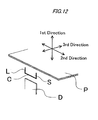
- the driver D drives the U-shape staple S toward the sheets P in a first direction
- the U-shape staple S includes a crown portion C extending in a second direction which is perpendicular to the first direction and leg portions L extending in the first direction from both ends of the crown portion C
- the stapler main body 1 may be supported swingably with respect to the base B around a rotating shaft 15 disposed on an opposite side to the table 4 in a third direction which is perpendicular to both the first direction and the second direction.
- the displacement is caused by the portion, which is located on the opposite side to the table and rotatably supported by the base, of the stapler main body. Therefore, the position of the rotating shaft is provided in the substantially same height position as the table, and respective positions of the clinching portion and the driver unit are seldom displaced even when the stapler main body is turned/ displaced. As a result, the stapling action can be done without fail.
- the stapler main body 1 may be supported to displace with respect to the base B in a manner of a parallel translation in a direction in which the driver D drives the staple S toward the sheets P.
- the displacement is caused by translating the stapler main body with respect to the base. Therefore, respective positions of the clinching portion and the driver unit are seldom displaced even when the stapler main body is displaced. As a result, the stapling action can be done without fail.
- a projection portion 27 may be formed on a cam 30 arranged on a driving shaft 21 provided on said one of the driver unit 2 and the clincher unit 3 on which the table 4 is provided.
- a cam follower 28 that is engagable with the projection portion 27 may be provided to the base B. The cam follower 28 may be engaged with the projection portion 27 in a standby state to restrict a displacement of the stapler main body 1.
- the projection portion of the cam engages with the cam follower, and the stapler main body is brought into the standby state. At this time, the stapler main body cannot be displaced, and is brought into the stable state. Since the cam is turned together with the driving shaft in the stapling action and thus the cam follower is released from the projection portion, the stapler main body is brought into a displaceable state.
- the projection portion of the cam engages with the cam follower again. Thus, the displacement of the stapler main body toward the upper side is restricted, and the stapler main body is brought into the stable state.
- the stapler main body can be stabilized by engaging the projection portion of the cam with the cam follower at the timing at which the stapler main body returns to its standby state after the stapling action is ended.
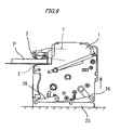
- FIG.1 is a perspective view of an electric stapler A of a first exemplary embodiment.
- the electric stapler A is provided to a paper processing equipment acting as a paper post processing equipment that is provided at a latter stage of an image forming apparatus such as a copying machine or a printer, or the like.
- the electric stapler A includes a base B.
- the base B is arranged on a frame member of the paper post processing equipment.
- a stapler main body 1 is arranged on a base B.
- a driver unit 2 is provided to the stapler main body 1.
- a clincher unit 3 is provided to the stapler main body 1 to swing in a vertical direction such that the clincher unit 3 moves toward/away from the driver unit 2 according to the swinging action.
- a table 4 is provided to the driver unit 2.
- a head portion 5 constructed such that a cartridge (not shown) including connected straight staples can be detachably attached to this portion is provided to the stapler main body 1.
- the head portion 5 forms the straight staple sent out from the cartridge, and then drives out this shaped stapler.
- the driver unit 2 for driving both a forming plate (not shown) for forming the straight staple into U-shape and a driver for driving out the U-shape staple is provided to the head portion 5.
- the straight staples in the cartridge are fed sequentially to the driver unit 2.
- the U-shape staple S when the direction (up/down direction) in which the driver D drives the U-shape staple S toward the sheets P is defined as a first direction, the U-shape staple S includes a crown portion C extending in a second direction (right/left direction) which is perpendicular to the first direction and leg portions L extending from both sides of the crown portion C in the first direction. Further, the direction (front/rear direction) which is perpendicular to both the first direction and the second direction is a third direction.
- the table 4 serves as a table that supports portions to be stapled of the sheets from a bottom side of the sheets, and is provided around a staple driving portion 6 provided on an upper surface of the head portion 5.
- a movable clincher for clinching the leg portions of the staple driven by the driver and its driving mechanism are provided in the clincher unit 3.
- the movable clincher is provided on a clinching portion 8 that is provided on an end of a drive link 7 which is swingably to the stapler main body 1.
- an electric motor M for driving both the driver unit 2 and the clincher unit 3 is disposed within the stapler main body 1.
- the sheets are fed through a space between the driver unit 2 and the clincher unit 3 and is put on the table 4. Then, when a power is turned ON, the drive link 7 is swung downward to come close to the table 4, and then sheets P are clamped between the table 4 and the drive link 7. Then, the staple is driven out from the driver unit 2, and then the staple is pierced through the sheets P to protrude upward. Then, the staple is clinched along a surface of the sheets P by the movable clincher of the clinching portion 8, and thus the stapling action is ended. After the stapling action is ended, the drive link 7 is moved to return to an upper standby position again.
- the base B serves as the member to which the stapler main body 1 is fitted, and an L-shaped base bracket 12 is formed on both sides of a bottom plate 10 and a rear plate 11. A top end of an upright portion 12a of the base bracket 12 is folded inwardly like a U-shape.
- the stapler main body 1 is arranged on the bottom plate 10.
- a bearing hole (not shown) is formed on the side surface of the stapler main body 1 in the height position substantially the same as the table 4 on the opposite side to the table 4 in the front-rear direction.
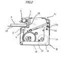
- a rotating shaft 15 (see FIG.2 ) is fitted into this bearing hole and a bearing hole 13 that is provided to a folded portion 14 at the top end of the upright portion of the base bracket 12.
- the rotating shaft 15 structures a supporting mechanism for supporting the stapler main body 1 so as to be displacable with respect to the base B. Accordingly, the stapler main body 1 can be displaced with respect to the base B so as to turn vertically around the rotating shaft 15.
- a reference numeral 16 denotes a guide plate that is used to feed the sheets P onto the table 4 of the electric stapler A and then staple them together. A part of the guide plate 16 is omitted herein from the illustration.
- This guide plate 16 is normally provided to a paper eject port of the paper processing equipment (the copying machine or the printer, or the like), and the copied or printed sheets of paper are stacked on the guide plate 16 via the sorter.
- a paper loading portion (loading surface) 17 is formed on the guide plate 16, and an opening portion 18 used to staple the sheets P is formed on the top end side by notching the paper loading portion 17. Top ends of the opening portion 18 on both sides are folded back by an almost right angle, and a top end wall 20 acts as a receiving plane that the edge of the sheets P hits.
- the folded portion of the guide plate 16 is arranged between the driver unit 2 of the stapler main body 1 and the clincher unit 3.
- the paper loading portion 17 of the guide plate 16 is arranged in a position that is higher than the table 4 by one step. Therefore, the opening portion 18 of the guide plate 16 faces to the table 4 on different levels, and also the electric stapler A can slide in the right/left direction with respect to the fixed guide plate 16. As a result, the sheets P can be stapled in different positions mutually by one electric stapler A.
- a plurality of sheets P are stacked on the guide plate 16 and are fed onto the table 4 of the electric stapler A, and then a power of the electric stapler A is turned ON.
- the drive link 7 of the clincher unit 3 is swung downward to come close to the table 4 of the driver unit 2, and is clamped.
- the paper loading portion 17 of the guide plate 16 and the table 4 of the driver unit 2 are positioned on different levels, and thus the bundle of the sheets P is set in a floating state over the table 4.
- the bundle of the sheets P is thick and has rigidity, such bundle is not so bent and the sheets P are set in a fixed state.
- the stapler main body 1 equipped with the driver unit 2 is turned/displaced around the rotating shaft 15 to constitute a substantially coplanar plane to the loading surface of the guide plate 16 of the table 4.
- the sheets P are clamped surely between the driver unit 2 and the clincher unit 3.
- a whole of the electric motor M is also displaceable with respect to the base B.
- the displacement movement of the stapler main body 1 is powered by the electric motor M.
- the staple is driven out from the driver unit 2, and then the staple is pierced through the sheets P to protrude upward. Then, the staple is clinched along the surface of the sheets P by the movable clincher of the clinching portion 8, and thus the stapling action is ended.
- the drive link 7 is moved to return to the upper standby position again, as shown in FIG. 1 , and thus the stapler main body 1 is also turned downward to return to the standby position.
- the sheets P are clamped surely between the driver unit 2 and the clincher unit 3. Therefore, the stapling action can be performed smoothly and surely.
- the position of the rotating shaft 15 is provided in the substantially same height position as the table 4. Therefore, respective positions of the clinching portion 8 and the driver unit are seldom displaced even when the stapler main body 1 is turned/displaced, and thus the stapling action can be performed without fail.
- the structure used to turn/displace the stapler main body is simple and achieved by utilizing the stapling action, another motor and another mechanism are not newly needed. As a result, a cost can be suppressed low, and also a size reduction of the overall stapler is not spoiled.
- any displacement of the stapler main body 1 may be employed if such displacement can move vertically the stapler main body by utilizing the stapling action.
- the displacing mode is not always limited to the displacement that is caused by utilizing the clamping action.
- the operations of a driving shaft and a cam provided to the stapler main body 1 may be utilized.
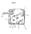
- a driving shaft 21 provided to the stapling side of the driver unit 2 is coupled to an output shaft of an electric motor in operation.
- An operation mode of the driving shaft 21 is set such that one cycle required until the stapler main body 1 returns to the standby state again after the stapling action is finished from the standby state is executed by one turn.
- a circular cam 22 is provided to the driving shaft 21, and an end portion of the drive link 7 of the clincher unit 3 is engaged with a cam groove (not shown) formed on the inner side of the cam.
- the stapling steps in one cycle are constructed such that, while the drive link 7 is caused by the cam groove during one turn of the cam 22 to swing downward from the upper standby position and then return to the upper standby position, the clincher unit 3 is shifted downward from the standby state, then the stapling action is performed, and then the clincher unit 3 is returned to the standby state.
- the driver unit 2 is constructed such that this driving portion is displaced from the standby position to the staple driving position and then the standby position during one turn of the driving shaft 21.
- a chord portion may be formed notching a part of an outer peripheral surface of the circular cam 22, a chord/circular arc portion 23 having a circular arc may be formed in the center of the chord portion, and a cam follower 24 may be provided in the position corresponding to the cam 22 on the bottom plate 10 of the base B.
- the staple is driven out from the driver unit 2, and then the staple is pierced through the sheets P to protrude upward. Then, the staple is clinched along the surface of the sheets P by the movable clincher of the clinching portion 8, and thus the stapling action is ended.
- the drive link 7 is moved to return to an upper standby position again, and also the stapler main body 1 is turned downward to return to the standby state.
- the stapler main body 1 can be turned/displaced while causing the outer peripheral surface of the cam 22 to engage with the cam follower 24 at the timing at which the drive link 7 of the clincher unit 3 is swung downward to clamp the sheets P.
- the cam follower 24 may engage with the chord/circular arc portion 23 again and may return to the position of the standby state.
- the displacement of the stapler main body 1 is not limited to the displacement that is given by the turning.
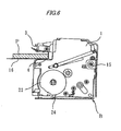
- the stapler main body 1 may be displaced by means of a parallel translation.
- a quadric crank link mechanism consisting of a base link 25 and two equilong links 26 provided turnably to the base link 25 respectively is constructed on the base B by providing the end portions of two links turnably to the lower portion of the side surface of the stapler main body 1.
- the stapler main body 1 in the stapling action, is displaced by the action of the link mechanism to move in parallel upwardly. Therefore, the table 4 is moved upward, and the table 4 and the sheets loading surface of the guide plate 16 constitute a substantially coplanar plane. Thus, the sheets P are clamped surely between the driver unit 2 and the clincher unit 3. Then, the staple is driven out from the driver unit 2, and then the staple is pierced through the sheets P to protrude upward. Then, the staple is clinched along the surface of the sheets P by the movable clincher of the clinching portion 8, and thus the stapling action is ended. After the stapling action is ended, the drive link 7 is moved to return to an upper standby position again, and also the stapler main body 1 is moved downward to return to the standby state.
- a plate spring, a coil spring, or the like may be provided between the base B and the stapler main body 1 or a guide may be provided such that the stapler main body 1 can move vertically to the base B.
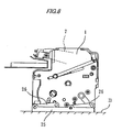
- a mechanism including a circular cam 30 (a second cam 30) and a cam follower 28 (a second cam follower 28) may be added to the structure of any one of the first to third exemplary embodiments.
- the circular cam 30 used to swing the other drive link (the drive links are provided as a pair on the right and left sides) like the cam 22 is provided on the opposite side to the above cam 22 that is provided to one end of the driving shaft 21 of the stapler main body 1. Therefore, a protruded circular edge is formed on the outer peripheral edge of the cam 30 as an internal cam, and a projection portion 27 protruded from the inner peripheral surface of the circular edge toward the inner side is formed on a part of the internal cam.
- the cam follower 28 is provided to the base bracket 12 in the position corresponding to the inner side of the circular edge. Then, in the standby state, the cam follower 28 is set to engage with the projection portion 27.
- the projection portion 27 of the cam 30 is engaged with the bottom of the cam follower 28, and the stapler main body 1 is brought into the standby state. At this time, the stapler main body 1 cannot be displaced and is set in a stable state.
- the cam 22 is turned together with the driving shaft 21 and the cam follower 28 is released from the projection portion, so that the stapler main body 1 is set in a displaceable state.
- the projection portion 27 of the cam 30 is engaged with the bottom of the cam follower 28 again.
- the stapler main body 1 is brought into the stable state. Since the driving shaft 21 performs the stapling action in one cycle every turn, the stapler main body 1 can be stabilized by engaging the projection portion 27 of the cam 30 with the top of the cam follower 28 at the timing at which the drive link 7 returns to the standby position after the stapling action is ended.
- the staple main body may be constructed such that the clincher unit and the driver unit are arranged oppositely in the vertical direction.
Landscapes
- Engineering & Computer Science (AREA)
- Mechanical Engineering (AREA)
- Life Sciences & Earth Sciences (AREA)
- Forests & Forestry (AREA)
- Dovetailed Work, And Nailing Machines And Stapling Machines For Wood (AREA)
- Portable Nailing Machines And Staplers (AREA)
Claims (13)
- Agrafeuse électrique comprenant :une base (B) ;un corps principal d'agrafeuse (1) agencé sur la base (B) et comprenant une unité d'entraînement (2) ayant un dispositif d'entraînement pour entraîner une agrafe (S) afin de percer des feuilles de papier (P), une unité de sertissage (3) ayant une pince à sertir pour sertir l'agrafe entraînée, et une table (4) prévue avec l'une parmi l'unité d'entraînement (2) et l'unité de sertissage (3) et sur laquelle les feuilles (P) sont supportées pendant une action d'agrafage ; etun mécanisme de support (15, 22, 24, 26) configuré pour supporter le corps principal d'agrafeuse (1) destiné à être déplacé par rapport à la base (B),dans laquelle la table (4) est configurée pour être mobile entre une première position et une seconde position espacée de la première position dans une direction dans laquelle le dispositif d'entraînement entraîne l'agrafe, selon un déplacement du corps principal d'agrafeuse (1) par rapport à la base (B),caractérisée en ce que :un moteur électrique (M) configuré pour entraîner à la fois l'unité d'entraînement (2) et l'unité de sertissage (3) est monté à l'intérieur du corps principal d'agrafeuse (1),un mouvement de déplacement du corps principal d'agrafeuse (1) par rapport à la base (B) est actionné par ledit moteur électrique (M), etle moteur électrique (M) est agencé à l'intérieur du corps principal d'agrafeuse (1) de sorte que l'ensemble du moteur électrique (M) est également déplaçable par rapport à la base (B) selon le mouvement de déplacement du corps principal d'agrafeuse (1).
- Agrafeuse électrique selon la revendication 1, dans laquelle, dans ladite première position, la table (4) se positionne à un niveau différent de l'une des surfaces des feuilles (P) dans un espace entre l'unité d'entraînement (2) et l'unité de sertissage (3), et
dans ladite seconde position, la table (4) et ladite une des surfaces des feuilles (P) forment un plan sensiblement coplanaire. - Agrafeuse électrique selon la revendication 1 ou 2, dans laquelle le corps principal d'agrafeuse (1) est configuré pour se déplacer par rapport à la base (B) selon l'action d'agrafage de l'unité d'entraînement (2) ou de l'unité de sertissage (3).
- Agrafeuse électrique selon l'une quelconque des revendications 1 à 3, dans laquelle le corps principal d'agrafeuse (1) est déplacé par une action de serrage au cours de laquelle les feuilles (P) sont serrées en amenant l'unité de sertissage (3) à proximité de l'unité d'entraînement (2) lors de l'action d'agrafage, de sorte que la table (4) passe dans la seconde position.
- Agrafeuse électrique selon l'une quelconque des revendications 1 à 3, comprenant en outre :une came (22) agencée sur un arbre d'entraînement (21) prévu sur ladite une parmi l'unité d'entraînement (2) et l'unité de sertissage (3) sur laquelle la table (4) est prévue ; etun poussoir de came (24) prévu sur la base (B) et mis en prise avec la came (22) ;dans laquelle le corps principal d'agrafeuse (1) est déplacé par rapport à la base (B) en faisant tourner la came (22) afin de modifier une distance entre l'arbre d'entraînement (21) et le poussoir de came (24), de sorte que la table (4) passe dans la seconde position.
- Agrafeuse électrique selon l'une quelconque des revendications 1 à 5, dans laquelle le dispositif d'entraînement (D) entraîne l'agrafe en forme de U (S) vers les feuilles (P) dans une première direction,
dans laquelle l'agrafe en forme de U (S) comprend une partie de couronne (C) s'étendant dans une deuxième direction qui est perpendiculaire à la première direction et des parties de patte (L) s'étendant dans la première direction à partir des deux extrémités de la partie de couronne (C),
dans laquelle le corps principal d'agrafeuse (1) est supporté de manière oscillante par rapport à la base (B) autour d'un arbre de rotation (15) disposé sur un côté opposé par rapport à la table (4) dans une troisième direction qui est perpendiculaire à la fois à la première direction et à la deuxième direction. - Agrafeuse électrique selon l'une quelconque des revendications 1 à 5, dans laquelle le corps principal d'agrafeuse (1) est supporté pour se déplacer par rapport à la base (B) selon une translation parallèle dans une direction dans laquelle le dispositif d'entraînement (D) entraîne l'agrafe (S) vers les feuilles (P).
- Agrafeuse électrique selon l'une quelconque des revendications 1 à 4, 6 et 7, dans laquelle une partie de saillie (27) est formée sur une came (30) agencée sur un arbre d'entraînement (21) prévu sur ladite une parmi l'unité d'entraînement (2) et l'unité de sertissage (3) sur laquelle la table (4) est prévue,
dans laquelle un poussoir de came (28) qui peut se mettre en prise avec la partie de saillie (27) est prévu sur la base (B), et
dans laquelle le poussoir de came (28) est mis en prise avec la partie de saillie (27) dans un état d'attente pour limiter un déplacement du corps principal d'agrafeuse (1). - Agrafeuse électrique selon la revendication 5, dans laquelle une seconde came (30) est agencée sur l'arbre d'entraînement (21),
dans laquelle une partie de saillie (27) est formée sur la seconde came (30),
dans laquelle le second poussoir de came (28) qui peut se mettre en prise avec la partie de saillie (27) est prévu sur la base (B), et
dans laquelle le second poussoir de came (28) est mis en prise avec la partie de saillie (27) dans un état d'attente pour limiter un déplacement du corps principal d'agrafeuse (1). - Equipement de traitement de papier comprenant :l'agrafeuse électrique selon l'une quelconque des revendications 1 à 9 ;une plaque de guidage (16) ; etune surface de chargement (17) sur laquelle les feuilles (P) sont chargées et qui est formée sur la plaque de guidage (16),dans lequel, dans ladite première position, la table (4) se positionne dans un niveau différent de la surface de chargement (17), etdans ladite seconde position, la table (4) et la surface de chargement (17) constituent un plan sensiblement coplanaire.
- Equipement de traitement de papier selon la revendication 10, dans lequel la base (B) est fixée sur un élément de châssis.
- Equipement de traitement de papier selon la revendication 10, dans lequel la base (B) est disposée sur un élément de châssis de sorte que la base (B) est mobile le long d'une direction d'un bord des feuilles (P).
- Equipement de traitement de papier selon la revendication 10, dans lequel la base (B) est disposée sur un élément de châssis de sorte que la base (B) est mobile dans une direction à proximité de/éloignée d'un bord des feuilles (P).
Applications Claiming Priority (1)
| Application Number | Priority Date | Filing Date | Title |
|---|---|---|---|
| JP2009207154A JP5333083B2 (ja) | 2009-09-08 | 2009-09-08 | 電動ステープラ |
Publications (3)
| Publication Number | Publication Date |
|---|---|
| EP2292394A2 EP2292394A2 (fr) | 2011-03-09 |
| EP2292394A3 EP2292394A3 (fr) | 2011-07-27 |
| EP2292394B1 true EP2292394B1 (fr) | 2012-10-17 |
Family
ID=43302725
Family Applications (1)
| Application Number | Title | Priority Date | Filing Date |
|---|---|---|---|
| EP10008473A Not-in-force EP2292394B1 (fr) | 2009-09-08 | 2010-08-13 | Agrafeuse électrique |
Country Status (4)
| Country | Link |
|---|---|
| US (1) | US9738007B2 (fr) |
| EP (1) | EP2292394B1 (fr) |
| JP (1) | JP5333083B2 (fr) |
| CN (1) | CN102009406B (fr) |
Families Citing this family (4)
| Publication number | Priority date | Publication date | Assignee | Title |
|---|---|---|---|---|
| US20140339284A1 (en) * | 2011-09-13 | 2014-11-20 | Olle Strååt | Link arrangement in a stapler |
| CN108725013A (zh) * | 2017-04-19 | 2018-11-02 | 丰民金属工业股份有限公司 | 电动钉书机 |
| CN110843057B (zh) * | 2019-11-29 | 2021-03-26 | 南京林业大学 | 一种防撞型物品包装格栅木箱制作辅助机械 |
| JP2023020678A (ja) * | 2021-07-30 | 2023-02-09 | マックス株式会社 | 装置 |
Family Cites Families (12)
| Publication number | Priority date | Publication date | Assignee | Title |
|---|---|---|---|---|
| JPS5254857Y2 (fr) * | 1972-07-20 | 1977-12-12 | ||
| US4720033A (en) * | 1986-05-05 | 1988-01-19 | Swingline Inc. | Motor-operated fastener driving machine with movable anvil |
| DE4020355C2 (de) * | 1990-06-27 | 1996-02-29 | Kodak Ag | Heftvorrichtung zum Zusammenheften von Blättern |
| JP3304590B2 (ja) * | 1994-02-01 | 2002-07-22 | 富士ゼロックス株式会社 | シート処理装置 |
| JP3247826B2 (ja) * | 1995-08-09 | 2002-01-21 | キヤノンアプテックス株式会社 | シ−ト後処理装置及びそれを備えた画像形成装置 |
| JP3473234B2 (ja) * | 1995-11-16 | 2003-12-02 | ニスカ株式会社 | ステープラ |
| JP3473233B2 (ja) * | 1995-11-16 | 2003-12-02 | ニスカ株式会社 | ステープラ |
| JP3476298B2 (ja) * | 1995-12-28 | 2003-12-10 | マックス株式会社 | 電動ホッチキス用カートリッジ |
| JP4277417B2 (ja) * | 2000-03-24 | 2009-06-10 | マックス株式会社 | 電動ステープラー |
| US6755337B2 (en) * | 2002-02-19 | 2004-06-29 | Acco Brands, Inc. | Powered stapler and adjustable base assembly |
| JP4239732B2 (ja) * | 2003-07-07 | 2009-03-18 | マックス株式会社 | 電動ステープラーの駆動機構 |
| JP4572566B2 (ja) * | 2004-04-09 | 2010-11-04 | マックス株式会社 | 自走式ステープラ |
-
2009
- 2009-09-08 JP JP2009207154A patent/JP5333083B2/ja active Active
-
2010
- 2010-08-13 EP EP10008473A patent/EP2292394B1/fr not_active Not-in-force
- 2010-08-18 US US12/858,966 patent/US9738007B2/en active Active
- 2010-09-08 CN CN201010279154.0A patent/CN102009406B/zh not_active Expired - Fee Related
Also Published As
| Publication number | Publication date |
|---|---|
| EP2292394A3 (fr) | 2011-07-27 |
| EP2292394A2 (fr) | 2011-03-09 |
| JP5333083B2 (ja) | 2013-11-06 |
| CN102009406A (zh) | 2011-04-13 |
| US20110057015A1 (en) | 2011-03-10 |
| CN102009406B (zh) | 2015-01-14 |
| JP2011056712A (ja) | 2011-03-24 |
| US9738007B2 (en) | 2017-08-22 |
Similar Documents
| Publication | Publication Date | Title |
|---|---|---|
| US20050017048A1 (en) | Electric stapler | |
| EP2292394B1 (fr) | Agrafeuse électrique | |
| WO2005099969A1 (fr) | Agrafeuse | |
| JP4232371B2 (ja) | ステープラー | |
| JP4296679B2 (ja) | 電動ステープラー | |
| JP2001269903A (ja) | 電動ホッチキス | |
| KR100519523B1 (ko) | 드라이버 유닛과 전동 스테플러 | |
| US8523039B2 (en) | Stapler | |
| EP2289678B1 (fr) | Agrafeuse électrique | |
| US6681975B2 (en) | Electric stapler | |
| JP2001239470A (ja) | 上下分離タイプのステープルシート後処理装置 | |
| US9162368B2 (en) | Electric stapler | |
| JP4923354B2 (ja) | ドライバユニットと電動ホッチキス | |
| US6769592B2 (en) | Stapler | |
| JP4304971B2 (ja) | 電動ステープラーにおける紙厚調整機構 | |
| JP3346195B2 (ja) | 電動ステープラ | |
| JP2003165104A (ja) | 電動ステープラ | |
| JP2007144551A (ja) | ステープラの綴り台構造 | |
| JPH0653074U (ja) | ホッチキス | |
| JP2012081544A (ja) | 電動ステープラ | |
| JP2003170404A (ja) | 電動ステープラ | |
| JP2003165106A (ja) | 電動ステープラ | |
| JP2003165105A (ja) | ステープラにおける用紙基準の移動機構 | |
| JPH0994770A (ja) | 電動ホッチキスにおけるドライバプレートの待機位置検出機構 | |
| JP2011131307A (ja) | 中綴じ用ステープラ及びその組み付け治具 |
Legal Events
| Date | Code | Title | Description |
|---|---|---|---|
| PUAI | Public reference made under article 153(3) epc to a published international application that has entered the european phase |
Free format text: ORIGINAL CODE: 0009012 |
|
| AK | Designated contracting states |
Kind code of ref document: A2 Designated state(s): AL AT BE BG CH CY CZ DE DK EE ES FI FR GB GR HR HU IE IS IT LI LT LU LV MC MK MT NL NO PL PT RO SE SI SK SM TR |
|
| AX | Request for extension of the european patent |
Extension state: BA ME RS |
|
| PUAL | Search report despatched |
Free format text: ORIGINAL CODE: 0009013 |
|
| AK | Designated contracting states |
Kind code of ref document: A3 Designated state(s): AL AT BE BG CH CY CZ DE DK EE ES FI FR GB GR HR HU IE IS IT LI LT LU LV MC MK MT NL NO PL PT RO SE SI SK SM TR |
|
| AX | Request for extension of the european patent |
Extension state: BA ME RS |
|
| RIC1 | Information provided on ipc code assigned before grant |
Ipc: B27F 7/19 20060101ALI20110621BHEP Ipc: B27F 7/00 20060101AFI20101220BHEP |
|
| 17P | Request for examination filed |
Effective date: 20120124 |
|
| GRAP | Despatch of communication of intention to grant a patent |
Free format text: ORIGINAL CODE: EPIDOSNIGR1 |
|
| RIC1 | Information provided on ipc code assigned before grant |
Ipc: B27F 7/19 20060101ALI20120425BHEP Ipc: B27F 7/00 20060101AFI20120425BHEP |
|
| GRAS | Grant fee paid |
Free format text: ORIGINAL CODE: EPIDOSNIGR3 |
|
| GRAA | (expected) grant |
Free format text: ORIGINAL CODE: 0009210 |
|
| AK | Designated contracting states |
Kind code of ref document: B1 Designated state(s): AL AT BE BG CH CY CZ DE DK EE ES FI FR GB GR HR HU IE IS IT LI LT LU LV MC MK MT NL NO PL PT RO SE SI SK SM TR |
|
| REG | Reference to a national code |
Ref country code: GB Ref legal event code: FG4D |
|
| REG | Reference to a national code |
Ref country code: CH Ref legal event code: EP |
|
| REG | Reference to a national code |
Ref country code: IE Ref legal event code: FG4D |
|
| REG | Reference to a national code |
Ref country code: AT Ref legal event code: REF Ref document number: 579674 Country of ref document: AT Kind code of ref document: T Effective date: 20121115 |
|
| REG | Reference to a national code |
Ref country code: DE Ref legal event code: R096 Ref document number: 602010003186 Country of ref document: DE Effective date: 20121213 |
|
| REG | Reference to a national code |
Ref country code: SE Ref legal event code: TRGR |
|
| REG | Reference to a national code |
Ref country code: NL Ref legal event code: T3 |
|
| REG | Reference to a national code |
Ref country code: AT Ref legal event code: MK05 Ref document number: 579674 Country of ref document: AT Kind code of ref document: T Effective date: 20121017 |
|
| REG | Reference to a national code |
Ref country code: LT Ref legal event code: MG4D |
|
| PG25 | Lapsed in a contracting state [announced via postgrant information from national office to epo] |
Ref country code: HR Free format text: LAPSE BECAUSE OF FAILURE TO SUBMIT A TRANSLATION OF THE DESCRIPTION OR TO PAY THE FEE WITHIN THE PRESCRIBED TIME-LIMIT Effective date: 20121017 Ref country code: FI Free format text: LAPSE BECAUSE OF FAILURE TO SUBMIT A TRANSLATION OF THE DESCRIPTION OR TO PAY THE FEE WITHIN THE PRESCRIBED TIME-LIMIT Effective date: 20121017 Ref country code: ES Free format text: LAPSE BECAUSE OF FAILURE TO SUBMIT A TRANSLATION OF THE DESCRIPTION OR TO PAY THE FEE WITHIN THE PRESCRIBED TIME-LIMIT Effective date: 20130128 Ref country code: LT Free format text: LAPSE BECAUSE OF FAILURE TO SUBMIT A TRANSLATION OF THE DESCRIPTION OR TO PAY THE FEE WITHIN THE PRESCRIBED TIME-LIMIT Effective date: 20121017 Ref country code: NO Free format text: LAPSE BECAUSE OF FAILURE TO SUBMIT A TRANSLATION OF THE DESCRIPTION OR TO PAY THE FEE WITHIN THE PRESCRIBED TIME-LIMIT Effective date: 20130117 Ref country code: IS Free format text: LAPSE BECAUSE OF FAILURE TO SUBMIT A TRANSLATION OF THE DESCRIPTION OR TO PAY THE FEE WITHIN THE PRESCRIBED TIME-LIMIT Effective date: 20130217 |
|
| PG25 | Lapsed in a contracting state [announced via postgrant information from national office to epo] |
Ref country code: GR Free format text: LAPSE BECAUSE OF FAILURE TO SUBMIT A TRANSLATION OF THE DESCRIPTION OR TO PAY THE FEE WITHIN THE PRESCRIBED TIME-LIMIT Effective date: 20130118 Ref country code: SI Free format text: LAPSE BECAUSE OF FAILURE TO SUBMIT A TRANSLATION OF THE DESCRIPTION OR TO PAY THE FEE WITHIN THE PRESCRIBED TIME-LIMIT Effective date: 20121017 Ref country code: PT Free format text: LAPSE BECAUSE OF FAILURE TO SUBMIT A TRANSLATION OF THE DESCRIPTION OR TO PAY THE FEE WITHIN THE PRESCRIBED TIME-LIMIT Effective date: 20130218 Ref country code: LV Free format text: LAPSE BECAUSE OF FAILURE TO SUBMIT A TRANSLATION OF THE DESCRIPTION OR TO PAY THE FEE WITHIN THE PRESCRIBED TIME-LIMIT Effective date: 20121017 Ref country code: PL Free format text: LAPSE BECAUSE OF FAILURE TO SUBMIT A TRANSLATION OF THE DESCRIPTION OR TO PAY THE FEE WITHIN THE PRESCRIBED TIME-LIMIT Effective date: 20121017 Ref country code: BE Free format text: LAPSE BECAUSE OF FAILURE TO SUBMIT A TRANSLATION OF THE DESCRIPTION OR TO PAY THE FEE WITHIN THE PRESCRIBED TIME-LIMIT Effective date: 20121017 |
|
| PG25 | Lapsed in a contracting state [announced via postgrant information from national office to epo] |
Ref country code: AT Free format text: LAPSE BECAUSE OF FAILURE TO SUBMIT A TRANSLATION OF THE DESCRIPTION OR TO PAY THE FEE WITHIN THE PRESCRIBED TIME-LIMIT Effective date: 20121017 |
|
| PG25 | Lapsed in a contracting state [announced via postgrant information from national office to epo] |
Ref country code: BG Free format text: LAPSE BECAUSE OF FAILURE TO SUBMIT A TRANSLATION OF THE DESCRIPTION OR TO PAY THE FEE WITHIN THE PRESCRIBED TIME-LIMIT Effective date: 20130117 Ref country code: DK Free format text: LAPSE BECAUSE OF FAILURE TO SUBMIT A TRANSLATION OF THE DESCRIPTION OR TO PAY THE FEE WITHIN THE PRESCRIBED TIME-LIMIT Effective date: 20121017 Ref country code: SK Free format text: LAPSE BECAUSE OF FAILURE TO SUBMIT A TRANSLATION OF THE DESCRIPTION OR TO PAY THE FEE WITHIN THE PRESCRIBED TIME-LIMIT Effective date: 20121017 Ref country code: EE Free format text: LAPSE BECAUSE OF FAILURE TO SUBMIT A TRANSLATION OF THE DESCRIPTION OR TO PAY THE FEE WITHIN THE PRESCRIBED TIME-LIMIT Effective date: 20121017 Ref country code: CZ Free format text: LAPSE BECAUSE OF FAILURE TO SUBMIT A TRANSLATION OF THE DESCRIPTION OR TO PAY THE FEE WITHIN THE PRESCRIBED TIME-LIMIT Effective date: 20121017 |
|
| PLBE | No opposition filed within time limit |
Free format text: ORIGINAL CODE: 0009261 |
|
| STAA | Information on the status of an ep patent application or granted ep patent |
Free format text: STATUS: NO OPPOSITION FILED WITHIN TIME LIMIT |
|
| PG25 | Lapsed in a contracting state [announced via postgrant information from national office to epo] |
Ref country code: RO Free format text: LAPSE BECAUSE OF FAILURE TO SUBMIT A TRANSLATION OF THE DESCRIPTION OR TO PAY THE FEE WITHIN THE PRESCRIBED TIME-LIMIT Effective date: 20121017 Ref country code: IT Free format text: LAPSE BECAUSE OF FAILURE TO SUBMIT A TRANSLATION OF THE DESCRIPTION OR TO PAY THE FEE WITHIN THE PRESCRIBED TIME-LIMIT Effective date: 20121017 |
|
| 26N | No opposition filed |
Effective date: 20130718 |
|
| REG | Reference to a national code |
Ref country code: DE Ref legal event code: R097 Ref document number: 602010003186 Country of ref document: DE Effective date: 20130718 |
|
| PG25 | Lapsed in a contracting state [announced via postgrant information from national office to epo] |
Ref country code: CY Free format text: LAPSE BECAUSE OF FAILURE TO SUBMIT A TRANSLATION OF THE DESCRIPTION OR TO PAY THE FEE WITHIN THE PRESCRIBED TIME-LIMIT Effective date: 20121017 |
|
| PG25 | Lapsed in a contracting state [announced via postgrant information from national office to epo] |
Ref country code: MC Free format text: LAPSE BECAUSE OF FAILURE TO SUBMIT A TRANSLATION OF THE DESCRIPTION OR TO PAY THE FEE WITHIN THE PRESCRIBED TIME-LIMIT Effective date: 20121017 |
|
| REG | Reference to a national code |
Ref country code: IE Ref legal event code: MM4A |
|
| PG25 | Lapsed in a contracting state [announced via postgrant information from national office to epo] |
Ref country code: IE Free format text: LAPSE BECAUSE OF NON-PAYMENT OF DUE FEES Effective date: 20130813 |
|
| REG | Reference to a national code |
Ref country code: CH Ref legal event code: PL |
|
| PG25 | Lapsed in a contracting state [announced via postgrant information from national office to epo] |
Ref country code: LI Free format text: LAPSE BECAUSE OF NON-PAYMENT OF DUE FEES Effective date: 20140831 Ref country code: CH Free format text: LAPSE BECAUSE OF NON-PAYMENT OF DUE FEES Effective date: 20140831 |
|
| PG25 | Lapsed in a contracting state [announced via postgrant information from national office to epo] |
Ref country code: SM Free format text: LAPSE BECAUSE OF FAILURE TO SUBMIT A TRANSLATION OF THE DESCRIPTION OR TO PAY THE FEE WITHIN THE PRESCRIBED TIME-LIMIT Effective date: 20121017 |
|
| PG25 | Lapsed in a contracting state [announced via postgrant information from national office to epo] |
Ref country code: MT Free format text: LAPSE BECAUSE OF FAILURE TO SUBMIT A TRANSLATION OF THE DESCRIPTION OR TO PAY THE FEE WITHIN THE PRESCRIBED TIME-LIMIT Effective date: 20121017 Ref country code: TR Free format text: LAPSE BECAUSE OF FAILURE TO SUBMIT A TRANSLATION OF THE DESCRIPTION OR TO PAY THE FEE WITHIN THE PRESCRIBED TIME-LIMIT Effective date: 20121017 |
|
| PG25 | Lapsed in a contracting state [announced via postgrant information from national office to epo] |
Ref country code: LU Free format text: LAPSE BECAUSE OF NON-PAYMENT OF DUE FEES Effective date: 20130813 Ref country code: HU Free format text: LAPSE BECAUSE OF FAILURE TO SUBMIT A TRANSLATION OF THE DESCRIPTION OR TO PAY THE FEE WITHIN THE PRESCRIBED TIME-LIMIT; INVALID AB INITIO Effective date: 20100813 Ref country code: MK Free format text: LAPSE BECAUSE OF FAILURE TO SUBMIT A TRANSLATION OF THE DESCRIPTION OR TO PAY THE FEE WITHIN THE PRESCRIBED TIME-LIMIT Effective date: 20121017 |
|
| REG | Reference to a national code |
Ref country code: FR Ref legal event code: PLFP Year of fee payment: 7 |
|
| REG | Reference to a national code |
Ref country code: FR Ref legal event code: PLFP Year of fee payment: 8 |
|
| PGFP | Annual fee paid to national office [announced via postgrant information from national office to epo] |
Ref country code: NL Payment date: 20170712 Year of fee payment: 8 |
|
| PGFP | Annual fee paid to national office [announced via postgrant information from national office to epo] |
Ref country code: DE Payment date: 20170808 Year of fee payment: 8 Ref country code: FR Payment date: 20170714 Year of fee payment: 8 Ref country code: GB Payment date: 20170809 Year of fee payment: 8 |
|
| PGFP | Annual fee paid to national office [announced via postgrant information from national office to epo] |
Ref country code: SE Payment date: 20170810 Year of fee payment: 8 |
|
| PG25 | Lapsed in a contracting state [announced via postgrant information from national office to epo] |
Ref country code: AL Free format text: LAPSE BECAUSE OF FAILURE TO SUBMIT A TRANSLATION OF THE DESCRIPTION OR TO PAY THE FEE WITHIN THE PRESCRIBED TIME-LIMIT Effective date: 20121017 |
|
| REG | Reference to a national code |
Ref country code: DE Ref legal event code: R119 Ref document number: 602010003186 Country of ref document: DE |
|
| REG | Reference to a national code |
Ref country code: SE Ref legal event code: EUG |
|
| REG | Reference to a national code |
Ref country code: NL Ref legal event code: MM Effective date: 20180901 |
|
| GBPC | Gb: european patent ceased through non-payment of renewal fee |
Effective date: 20180813 |
|
| PG25 | Lapsed in a contracting state [announced via postgrant information from national office to epo] |
Ref country code: SE Free format text: LAPSE BECAUSE OF NON-PAYMENT OF DUE FEES Effective date: 20180814 |
|
| PG25 | Lapsed in a contracting state [announced via postgrant information from national office to epo] |
Ref country code: NL Free format text: LAPSE BECAUSE OF NON-PAYMENT OF DUE FEES Effective date: 20180901 |
|
| PG25 | Lapsed in a contracting state [announced via postgrant information from national office to epo] |
Ref country code: DE Free format text: LAPSE BECAUSE OF NON-PAYMENT OF DUE FEES Effective date: 20190301 |
|
| PG25 | Lapsed in a contracting state [announced via postgrant information from national office to epo] |
Ref country code: FR Free format text: LAPSE BECAUSE OF NON-PAYMENT OF DUE FEES Effective date: 20180831 |
|
| PG25 | Lapsed in a contracting state [announced via postgrant information from national office to epo] |
Ref country code: GB Free format text: LAPSE BECAUSE OF NON-PAYMENT OF DUE FEES Effective date: 20180813 |