EP2287474A2 - Struktur zur Befestigung eines Clips an einer Innenausstattungstafel, Clip und Clipbefestigungsverfahren - Google Patents
Struktur zur Befestigung eines Clips an einer Innenausstattungstafel, Clip und Clipbefestigungsverfahren Download PDFInfo
- Publication number
- EP2287474A2 EP2287474A2 EP10173241A EP10173241A EP2287474A2 EP 2287474 A2 EP2287474 A2 EP 2287474A2 EP 10173241 A EP10173241 A EP 10173241A EP 10173241 A EP10173241 A EP 10173241A EP 2287474 A2 EP2287474 A2 EP 2287474A2
- Authority
- EP
- European Patent Office
- Prior art keywords
- clip
- fastening
- diameter portion
- latch lugs
- pair
- Prior art date
- Legal status (The legal status is an assumption and is not a legal conclusion. Google has not performed a legal analysis and makes no representation as to the accuracy of the status listed.)
- Withdrawn
Links
- 238000000034 method Methods 0.000 title claims description 4
- 230000007423 decrease Effects 0.000 claims description 15
- 230000005489 elastic deformation Effects 0.000 claims description 11
- 238000005452 bending Methods 0.000 claims description 5
- 230000036544 posture Effects 0.000 description 17
- 239000000463 material Substances 0.000 description 6
- 230000003247 decreasing effect Effects 0.000 description 5
- 229920003002 synthetic resin Polymers 0.000 description 4
- 239000000057 synthetic resin Substances 0.000 description 4
- 238000005516 engineering process Methods 0.000 description 3
- 238000000465 moulding Methods 0.000 description 3
- 230000000694 effects Effects 0.000 description 2
- 238000004519 manufacturing process Methods 0.000 description 2
- 238000012986 modification Methods 0.000 description 2
- 230000004048 modification Effects 0.000 description 2
- 230000004323 axial length Effects 0.000 description 1
- -1 for example Substances 0.000 description 1
- 238000010348 incorporation Methods 0.000 description 1
- 239000007769 metal material Substances 0.000 description 1
- 230000002093 peripheral effect Effects 0.000 description 1
- 230000000630 rising effect Effects 0.000 description 1
Images


Classifications
-
- F—MECHANICAL ENGINEERING; LIGHTING; HEATING; WEAPONS; BLASTING
- F16—ENGINEERING ELEMENTS AND UNITS; GENERAL MEASURES FOR PRODUCING AND MAINTAINING EFFECTIVE FUNCTIONING OF MACHINES OR INSTALLATIONS; THERMAL INSULATION IN GENERAL
- F16B—DEVICES FOR FASTENING OR SECURING CONSTRUCTIONAL ELEMENTS OR MACHINE PARTS TOGETHER, e.g. NAILS, BOLTS, CIRCLIPS, CLAMPS, CLIPS OR WEDGES; JOINTS OR JOINTING
- F16B5/00—Joining sheets or plates, e.g. panels, to one another or to strips or bars parallel to them
- F16B5/12—Fastening strips or bars to sheets or plates, e.g. rubber strips, decorative strips for motor vehicles, by means of clips
- F16B5/123—Auxiliary fasteners specially designed for this purpose
-
- B—PERFORMING OPERATIONS; TRANSPORTING
- B60—VEHICLES IN GENERAL
- B60R—VEHICLES, VEHICLE FITTINGS, OR VEHICLE PARTS, NOT OTHERWISE PROVIDED FOR
- B60R13/00—Elements for body-finishing, identifying, or decorating; Arrangements or adaptations for advertising purposes
- B60R13/02—Internal Trim mouldings ; Internal Ledges; Wall liners for passenger compartments; Roof liners
- B60R13/0206—Arrangements of fasteners and clips specially adapted for attaching inner vehicle liners or mouldings
-
- F—MECHANICAL ENGINEERING; LIGHTING; HEATING; WEAPONS; BLASTING
- F16—ENGINEERING ELEMENTS AND UNITS; GENERAL MEASURES FOR PRODUCING AND MAINTAINING EFFECTIVE FUNCTIONING OF MACHINES OR INSTALLATIONS; THERMAL INSULATION IN GENERAL
- F16B—DEVICES FOR FASTENING OR SECURING CONSTRUCTIONAL ELEMENTS OR MACHINE PARTS TOGETHER, e.g. NAILS, BOLTS, CIRCLIPS, CLAMPS, CLIPS OR WEDGES; JOINTS OR JOINTING
- F16B21/00—Means for preventing relative axial movement of a pin, spigot, shaft or the like and a member surrounding it; Stud-and-socket releasable fastenings
- F16B21/06—Releasable fastening devices with snap-action
- F16B21/07—Releasable fastening devices with snap-action in which the socket has a resilient part
- F16B21/071—Releasable fastening devices with snap-action in which the socket has a resilient part the socket being integrally formed with a component to be fasted, e.g. a sheet, plate or strip
-
- F—MECHANICAL ENGINEERING; LIGHTING; HEATING; WEAPONS; BLASTING
- F16—ENGINEERING ELEMENTS AND UNITS; GENERAL MEASURES FOR PRODUCING AND MAINTAINING EFFECTIVE FUNCTIONING OF MACHINES OR INSTALLATIONS; THERMAL INSULATION IN GENERAL
- F16B—DEVICES FOR FASTENING OR SECURING CONSTRUCTIONAL ELEMENTS OR MACHINE PARTS TOGETHER, e.g. NAILS, BOLTS, CIRCLIPS, CLAMPS, CLIPS OR WEDGES; JOINTS OR JOINTING
- F16B5/00—Joining sheets or plates, e.g. panels, to one another or to strips or bars parallel to them
- F16B5/12—Fastening strips or bars to sheets or plates, e.g. rubber strips, decorative strips for motor vehicles, by means of clips
- F16B5/126—Fastening strips or bars to sheets or plates, e.g. rubber strips, decorative strips for motor vehicles, by means of clips at least one of the sheets, plates, bars or strips having integrally formed or integrally connected snap-in-features
-
- F—MECHANICAL ENGINEERING; LIGHTING; HEATING; WEAPONS; BLASTING
- F16—ENGINEERING ELEMENTS AND UNITS; GENERAL MEASURES FOR PRODUCING AND MAINTAINING EFFECTIVE FUNCTIONING OF MACHINES OR INSTALLATIONS; THERMAL INSULATION IN GENERAL
- F16B—DEVICES FOR FASTENING OR SECURING CONSTRUCTIONAL ELEMENTS OR MACHINE PARTS TOGETHER, e.g. NAILS, BOLTS, CIRCLIPS, CLAMPS, CLIPS OR WEDGES; JOINTS OR JOINTING
- F16B5/00—Joining sheets or plates, e.g. panels, to one another or to strips or bars parallel to them
- F16B5/12—Fastening strips or bars to sheets or plates, e.g. rubber strips, decorative strips for motor vehicles, by means of clips
- F16B5/128—Fastening strips or bars to sheets or plates, e.g. rubber strips, decorative strips for motor vehicles, by means of clips a strip with a C-or U-shaped cross section being fastened to a plate such that the fastening means remain invisible, e.g. the fastening being completely enclosed by the strip
-
- F—MECHANICAL ENGINEERING; LIGHTING; HEATING; WEAPONS; BLASTING
- F16—ENGINEERING ELEMENTS AND UNITS; GENERAL MEASURES FOR PRODUCING AND MAINTAINING EFFECTIVE FUNCTIONING OF MACHINES OR INSTALLATIONS; THERMAL INSULATION IN GENERAL
- F16B—DEVICES FOR FASTENING OR SECURING CONSTRUCTIONAL ELEMENTS OR MACHINE PARTS TOGETHER, e.g. NAILS, BOLTS, CIRCLIPS, CLAMPS, CLIPS OR WEDGES; JOINTS OR JOINTING
- F16B21/00—Means for preventing relative axial movement of a pin, spigot, shaft or the like and a member surrounding it; Stud-and-socket releasable fastenings
- F16B21/06—Releasable fastening devices with snap-action
- F16B21/08—Releasable fastening devices with snap-action in which the stud, pin, or spigot has a resilient part
- F16B21/086—Releasable fastening devices with snap-action in which the stud, pin, or spigot has a resilient part the shank of the stud, pin or spigot having elevations, ribs, fins or prongs intended for deformation or tilting predominantly in a direction perpendicular to the direction of insertion
-
- F—MECHANICAL ENGINEERING; LIGHTING; HEATING; WEAPONS; BLASTING
- F16—ENGINEERING ELEMENTS AND UNITS; GENERAL MEASURES FOR PRODUCING AND MAINTAINING EFFECTIVE FUNCTIONING OF MACHINES OR INSTALLATIONS; THERMAL INSULATION IN GENERAL
- F16B—DEVICES FOR FASTENING OR SECURING CONSTRUCTIONAL ELEMENTS OR MACHINE PARTS TOGETHER, e.g. NAILS, BOLTS, CIRCLIPS, CLAMPS, CLIPS OR WEDGES; JOINTS OR JOINTING
- F16B21/00—Means for preventing relative axial movement of a pin, spigot, shaft or the like and a member surrounding it; Stud-and-socket releasable fastenings
- F16B21/06—Releasable fastening devices with snap-action
- F16B21/08—Releasable fastening devices with snap-action in which the stud, pin, or spigot has a resilient part
- F16B21/088—Releasable fastening devices with snap-action in which the stud, pin, or spigot has a resilient part the stud, pin or spigot being integrally formed with the component to be fastened, e.g. forming part of the sheet, plate or strip
-
- Y—GENERAL TAGGING OF NEW TECHNOLOGICAL DEVELOPMENTS; GENERAL TAGGING OF CROSS-SECTIONAL TECHNOLOGIES SPANNING OVER SEVERAL SECTIONS OF THE IPC; TECHNICAL SUBJECTS COVERED BY FORMER USPC CROSS-REFERENCE ART COLLECTIONS [XRACs] AND DIGESTS
- Y10—TECHNICAL SUBJECTS COVERED BY FORMER USPC
- Y10T—TECHNICAL SUBJECTS COVERED BY FORMER US CLASSIFICATION
- Y10T24/00—Buckles, buttons, clasps, etc.
- Y10T24/30—Trim molding fastener
- Y10T24/303—Trim molding fastener having laterally extending biasing appendage
-
- Y—GENERAL TAGGING OF NEW TECHNOLOGICAL DEVELOPMENTS; GENERAL TAGGING OF CROSS-SECTIONAL TECHNOLOGIES SPANNING OVER SEVERAL SECTIONS OF THE IPC; TECHNICAL SUBJECTS COVERED BY FORMER USPC CROSS-REFERENCE ART COLLECTIONS [XRACs] AND DIGESTS
- Y10—TECHNICAL SUBJECTS COVERED BY FORMER USPC
- Y10T—TECHNICAL SUBJECTS COVERED BY FORMER US CLASSIFICATION
- Y10T24/00—Buckles, buttons, clasps, etc.
- Y10T24/30—Trim molding fastener
- Y10T24/309—Plastic type
-
- Y—GENERAL TAGGING OF NEW TECHNOLOGICAL DEVELOPMENTS; GENERAL TAGGING OF CROSS-SECTIONAL TECHNOLOGIES SPANNING OVER SEVERAL SECTIONS OF THE IPC; TECHNICAL SUBJECTS COVERED BY FORMER USPC CROSS-REFERENCE ART COLLECTIONS [XRACs] AND DIGESTS
- Y10—TECHNICAL SUBJECTS COVERED BY FORMER USPC
- Y10T—TECHNICAL SUBJECTS COVERED BY FORMER US CLASSIFICATION
- Y10T24/00—Buckles, buttons, clasps, etc.
- Y10T24/44—Clasp, clip, support-clamp, or required component thereof
- Y10T24/44017—Clasp, clip, support-clamp, or required component thereof with specific mounting means for attaching to rigid or semirigid supporting structure or structure-to-be-secured
- Y10T24/44026—Clasp, clip, support-clamp, or required component thereof with specific mounting means for attaching to rigid or semirigid supporting structure or structure-to-be-secured for cooperating with aperture in supporting structure or structure-to-be-secured
-
- Y—GENERAL TAGGING OF NEW TECHNOLOGICAL DEVELOPMENTS; GENERAL TAGGING OF CROSS-SECTIONAL TECHNOLOGIES SPANNING OVER SEVERAL SECTIONS OF THE IPC; TECHNICAL SUBJECTS COVERED BY FORMER USPC CROSS-REFERENCE ART COLLECTIONS [XRACs] AND DIGESTS
- Y10—TECHNICAL SUBJECTS COVERED BY FORMER USPC
- Y10T—TECHNICAL SUBJECTS COVERED BY FORMER US CLASSIFICATION
- Y10T24/00—Buckles, buttons, clasps, etc.
- Y10T24/45—Separable-fastener or required component thereof [e.g., projection and cavity to complete interlock]
- Y10T24/45005—Separable-fastener or required component thereof [e.g., projection and cavity to complete interlock] with third detached member completing interlock [e.g., hook type]
- Y10T24/45099—Resilient element [e.g., snap type]
- Y10T24/45105—Resilient element [e.g., snap type] for upholstery, panel, trim strip, etc. [e.g., spring biased]
-
- Y—GENERAL TAGGING OF NEW TECHNOLOGICAL DEVELOPMENTS; GENERAL TAGGING OF CROSS-SECTIONAL TECHNOLOGIES SPANNING OVER SEVERAL SECTIONS OF THE IPC; TECHNICAL SUBJECTS COVERED BY FORMER USPC CROSS-REFERENCE ART COLLECTIONS [XRACs] AND DIGESTS
- Y10—TECHNICAL SUBJECTS COVERED BY FORMER USPC
- Y10T—TECHNICAL SUBJECTS COVERED BY FORMER US CLASSIFICATION
- Y10T24/00—Buckles, buttons, clasps, etc.
- Y10T24/45—Separable-fastener or required component thereof [e.g., projection and cavity to complete interlock]
- Y10T24/45225—Separable-fastener or required component thereof [e.g., projection and cavity to complete interlock] including member having distinct formations and mating member selectively interlocking therewith
- Y10T24/45602—Receiving member includes either movable connection between interlocking components or variable configuration cavity
- Y10T24/45775—Receiving member includes either movable connection between interlocking components or variable configuration cavity having resiliently biased interlocking component or segment
Definitions
- the invention relates to a structure for fastening a clip to a trim board of a vehicle, and more specifically to a technology for making it possible to simultaneously fit multiple clips to clip fitting seats formed at multiple locations of a trim board.
- This clip has a) a first projection that is fastened to a clip fitting seat of the trim board, and b) a second projection that is fastened to the vehicle body-side member. c) As the second projection is fastened to the vehicle body-side member with the first projection fastened to the trim board, the trim board is fixed to the vehicle body-side member.
- Japanese Patent Application Publication No. 2004-183798 JP-A-2004-183798 ) describes an example of the above-described fastening structure.
- a ball is provided as a first projection, and a spherical recess is formed in a cylindrical clip fitting seat formed on a trim board.
- the ball is inserted into the clip fitting seat in a direction perpendicular to the trim board and then fitted into the spherical recess, and widening prevented ribs are engaged with an outer periphery of the clip fitting seat.
- a clip is fastened to the trim board.
- the clip is fastened to the trim board in one stroke so that the ball of the clip is fitted into the spherical recess, that is called fastened state, the clip is removed from the spherical recess. Therefore, it is difficult to simultaneously fit the multiple clips to the clip fitting seats with the use of, for example, a press machine.
- the multiple clip fitting seats are formed on the trim board, and the trim board is fixed to a vehicle body-side member via the multiple clips. Therefore, it is necessary to perform a cumbersome work, that is, to fit the multiple clips one by one to the clip fitting seats. Even when the clips are pushed by a press machine to be fastened to the clip fitting seats, it is necessary to fit the clips one by one to the clip fitting seats. Accordingly, fastening the clips to the clip fitting seats takes a long time, which is not efficient.
- the invention is made in light of the above-described circumstances. It is therefore an object of the invention to make it possible to simultaneously fit multiple clips to clip fitting seats formed at multiple locations of a trim board with the use of, for example, a press machine.
- a first aspect of the invention which provides a structure for fastening a clip to a trim board, the clip having a first projection that is fastened to a clip fitting seat of the trim board and a second projection that is fastened to a vehicle body-side member, and fixing the trim board integrally to the vehicle body-side member as the second projection is fastened to the vehicle body-side member with the first projection fastened to the trim board, wherein:
- the object indicated above may be achieved according to a second aspect of the invention, which provides the structure for fastening the clip to the trim board according to the first aspect of the invention, wherein: (a) the first projection has a small-diameter portion, a constricted portion that is smaller in diameter than the small-diameter portion, a large-diameter portion that is larger in diameter than the small-diameter portion, and a small-diameter fitted portion formed between the large-diameter portion and a seating portion that is seated on the clip fitting seat, which are formed concentrically with each other and which are located in this order from a tip end of the first projection in a direction in which the first projection is pushed into the clip fitting seat; (b) the clip fitting seat has a set of the latch lugs that is engaged with the small-diameter portion and the large-diameter portion in this order when the first projection is relatively pushed into the clip fitting seat in the fastening direction, and the distance between the latch lugs
- a third aspect of the invention which provides the structure for fastening the clip to the trim board according to the second aspect of the invention, wherein: (a) the large-diameter portion has a tapered face having a diameter that decreases toward the constricted portion, and the set of latch lugs has partially tapered holding faces that correspond to the tapered face; and (b) in the intermediate fastened state, the latch lugs are located at the constricted portion so as to be clamped between the large-diameter portion and the small-diameter portion, and the tapered face of the large-diameter portion is in surface-contact with the holding faces of the latch lugs so that the clip is positioned so as to take a certain posture.
- the clip fitting seat is formed of a pair of lug members which extend from the trim board and of which upper end portions are apart from each other by a clearance g that is smaller than the small-diameter portion; a pair of the latch lugs is formed in the upper end portions of the pair of lug members so as to face each other; and the distance between the pair of latch lugs is enlarged due to elastic deformation of the pair of lug members so that each of the small-diameter portion and the large-diameter portion is permitted to pass through between the pair of latch lugs.
- a fifth aspect of the invention which provides the structure for fastening the clip to the trim board according to the fourth aspect of the invention, wherein end portions of the pair of latch lugs have arc-shaped portions centering on a fitting axis O for fastening the clip and having a diameter d that is smaller than the small-diameter portion and larger than the clearance g between the pair of lug members when viewed from the fastening direction.
- the pair of lug members has a pair of vertical plate portions that rise up from the trim board so as to be parallel to each other, and lateral plate portions that extend from upper end portions of the vertical plate portions bent in a direction that is substantially perpendicular to the vertical plate portions in such a manner that end portions of the lateral plate portions face each other with the clearance g left therebetween; and (b) the end portions of the lateral plate portions are stepped portions that are formed by bending to recess the end portions of the lateral plate portions toward the trim board, and the stepped portions are used as the latch lugs.
- a seventh aspect of the invention which provides the structure for fastening the clip to the trim board according to the fourth or fifth aspect of the invention, wherein: (a) the pair of lug members has a pair of vertical plate portions that rise up from the trim board, and are substantially parallel to each other with the clearance g left therebetween at least upper end portions of the pair of vertical plate portions, and the latch lugs are formed integrally with portions of the upper end portions, which face each other; and (b) through-holes are formed in portions of the vertical-plate portions, which are immediately below the latch lugs, and each of the small-diameter portion and the large-diameter portion, which has passed through between the latch lugs while elastically deforming the vertical plate portions in such a manner that the vertical plate portions are further apart from each other, is latched with an upper edges of the through-holes so as to be prevented from being removed.
- an eighth aspect of the invention which provides the structure for fastening the clip to the trim board according to any one of the first to seventh aspects of the invention, wherein a plurality of the clip fitting seats, to which the clips are fastened and of which the fastening directions are parallel to each other, is formed on the trim board.
- a ninth aspect of the invention which provides the clip used in the structure for fastening the clip to the trim board according to any one of the second to seventh aspects of the invention.
- a tenth aspect of the invention which provides a method for fastening the clips to the multiple clip fitting seats in the structure for fastening the clip to the trim board according to the eighth aspect of the invention, including: (a) an intermediate fastening step for achieving the intermediate fastened state by relatively moving the clips close to the multiple clip fitting seats in the fastening directions; and (b) a final fastening step for achieving the final fastened state by simultaneously relatively pushing the multiple clips fastened to the clip fitting seats in the intermediate fastened state in the fastening directions by a pushing machine.
- the first projection has an engagement portion having a diameter that locally increases and decreases in a predetermined fastening direction that is substantially perpendicular to the trim board and the clip fitting seat has multiple latch lugs that are used to position the clip and elastically deformed in such a manner that a distance between the latch lugs is enlargeable as the engagement portion is engaged with the latch lugs, so that the first projection is fastened to the clip fitting seat by being pushed in the fastening direction; and at least two types of the engagement portions that differ in diameter are formed in the first projection at locations that are apart from each other in the fastening direction or at least two sets of the latch lugs that differ in engaging area, at which the latch lugs are engaged with the engagement portion, are formed in the clip fitting seat at locations that are apart from each other in the fastening direction, so that the clip is fastened to the clip fitting seat in at least two staged fastened states which include an intermediate fastened state that is achieved by fastening the clip to the clip fitting seat at least two staged fastened states which
- the clip fitting seat in the intermediate fastened state it is possible to fasten the clip to the clip fitting seat in the intermediate fastened state, and the clip is pushed in the predetermined fastening direction, which is substantially perpendicular to the trim board, to be fastened to the clip fitting seat. Therefore, even if the multiple clip fitting seats are formed, the clips, which have been, for example, manually fastened to the clip fitting seats in the intermediate fastened state, are simultaneously pushed into the clip fitting seats by, for example, a single press machine to achieve the final fastened state. Therefore, it is possible to increase the efficiency of the clip fastening work, and to automatically perform the clip fastening work.
- the first projection of the clip has a small-diameter portion, a constricted portion, a large-diameter portion and a fitted portion that are formed concentrically with each other from a tip end of the first projection in this order in a direction in which the clip is pushed into the clip fitting seat.
- the intermediate fastened state where the latch lugs are located at the constricted portion is achieved.
- the large-diameter portion passes through between the latch lugs while elastically enlarging the distance between the latch lugs.
- the final fastened state where the latch lugs are located at the fitted portion is achieved.
- multiple constricted portions for achieving the intermediate fastened states may be formed in the first projection so that the multiple constricted portions pass through between the latch lags before the latch lugs reach the fitted portion.
- the structure are formed in such a manner that at least two staged fastened states are achieved.
- the small-diameter portion that is located at the tip end of the first projection is smaller in diameter than the large-diameter portion, it is possible to relatively easily push the clip into the clip fitting seat. Therefore, the intermediate fastened state is easily achieved, for example, manually.
- the large-diameter portion that is larger in diameter than the small-diameter portion need to pass through between the latch lugs. Therefore, the clip is pushed with a relatively large pushing force (at high fastening load) by, for example, the press machine. Thus, it is possible to fasten the clip to the clip fitting seat with predetermined fastening strength.
- the large-diameter portion has a tapered face having a diameter that decreases toward the constricted portion, and the set of latch lugs has partially tapered holding faces that correspond to the tapered face; and in the intermediate fastened state, the tapered face of the large-diameter portion is in surface-contact with the holding faces of the latch lugs so that the clip is positioned so as to take a certain posture.
- the posture of the clip in the intermediate fastened state is stabilized. Therefore, when the clip is further pushed to be placed in the final fastened state, it is possible to prevent product failure, which may be caused if the clip falls down. As a result, the production yield is improved.
- the clip fitting seat is formed of a pair of lug members which extend from the trim board; a pair of the latch lugs is formed in the upper end portions of the pair of lug members so as to face each other; and the distance between the pair of latch lugs is enlarged due to elastic deformation of the pair of lug members so that each of the small-diameter portion and the large-diameter portion is permitted to pass through between the pair of latch lugs.
- each of the small-diameter portion and the large-diameter portion is permitted to pass through between the latch lugs due to elastic deformation of the pair of lug members.
- the stiffness of the latch lugs is higher and the clip is more firmly fastened to the clip fitting seat with higher fastening strength than when, for example, only the latch lugs, which are part of the lug members, are elastically deformed.
- end portions of the pair of latch lugs have arc-shaped portions centering on a fitting axis O for fastening the clip and having a diameter d that is smaller than the small-diameter portion and larger than the clearance g between the pair of lug members. Due to the arc-shaped portions of the pair of latch lugs, the clip is fastened to the trim board in such a manner that the central axis of the clip coincides with the fitting axis O at high position accuracy. As a result, it is possible to more easily perform the work for fixing the trim board to the vehicle body-side member via the clip.
- the pair of lug members has a pair of vertical plate portions that rise up from the trim board so as to be parallel to each other, and lateral plate portions that extend from upper end portions of the vertical plate portions bent in a direction that is substantially perpendicular to the vertical plate portions in such a manner that end portions of the lateral plate portions are stepped portions that are formed by bending to recess the end portions of the lateral plate portions toward the trim board, and the stepped portions are used as the latch lugs.
- the clip fitting seat has a pair of vertical plate portions, and the latch lugs are formed with portions of upper end portions of the pair of the vertical plate portions, which face each other; and through-holes are formed in portions, which are immediately below the latch lugs, and each of the small-diameter portion and the large-diameter portion, which has passed through between the latch lugs while elastically deforming the vertical plate portions in such a manner that the vertical plate portions are further apart from each other, is latched with an upper edges of the through-holes so as to be prevented from being removed.
- the latched state of the small-diameter portion or the large-diameter portion is visually checked directly through the through-holes.
- each of the small-diameter portion and the large-diameter portion of the clip passes through between the latch lugs while elastically deforming the vertical plate portions. Therefore, the stiffness of the latch lugs is higher and the clip is more firmly fastened to the clip fitting seat with higher fastening strength than when only the latch lugs, which are part of the lug members, are elastically deformed. In addition, it is possible to appropriately adjust stiffness of the vertical plate portions, and, consequently, fastening strength for the clip by changing sizes and locations of the through-holes.
- the intermediate fastened state is achieved by relatively moving the clips close to the multiple clip fitting seats in the fastening directions where a plurality of the clip fitting seats is formed on the trim board; and then the final fastened state is achieved by simultaneously relatively pushing the multiple clips fastened to the clip fitting seats in the intermediate fastened state in the fastening directions by a pushing machine. Consequently, the multiple clips can be effectively fastened.
- the invention relates to a structure for fastening a clip to a trim board, the clip being used to fix the trim board (interior parts), for example, a door trim or an instrument panel, to a vehicle body-side member, for example, an inner panel.
- the trim board is usually made of synthetic resin material, and, for example, an upholstery material is provided on a surface of the trim board when needed.
- the clip has, for example, a first projection and a second projection that are aligned along a single straight line so as to extend in opposite directions, that is, extend outward.
- the clip is also made of synthetic resin material.
- the clip may be made of another material, for example, metal material.
- multiple clip fitting seats are formed integrally with the trim board, and the clips are fastened to the clip fitting seats.
- the trim board is fixed to the vehicle body-side member via the multiple clips.
- the multiple clip fitting seats are formed in such postures that fastening directions, in which the clips are fastened to the clip fitting seats, are parallel to each other and are substantially perpendicular to the trim board.
- the fastening directions are substantially perpendicular to the trim board so that the multiple clips are simultaneously fitted to the clip fitting seats. Therefore, the fastening directions need not be exactly perpendicular to the trim board.
- the fastening directions may be oblique to the trim board at a predetermined angle.
- the trim board need not have a flat face.
- the trim board may be curved or have recesses and projections.
- the clip fitting seats need not be formed in uniform postures with respect to the trim board, for example, the postures in which the clip fitting seats are perpendicular to the trim board, as long as the fastening directions in which the clips are fastened to the clip fitting seats are parallel to each other.
- the clip When the clip is fastened to the clip fitting seat of the trim board, the clip may be moved toward the trim board. Alternatively, the trim board may be moved toward the clip. The manner in which the clip is fastened to the clip fitting seat may be different between an intermediate fastening step and a final fastening step.
- the first projection has a small-diameter portion, a constricted portion, a large-diameter portion and a fitted portion that are formed concentrically with each other from a tip end of the first projection in this order in a direction in which the clip is pushed into the clip fitting seat.
- Two fastened states that is, an intermediate fastened state where latch lugs are located at the constricted portion and a final fastened state where the latch lugs are located at the fitted portion are achieved.
- the structure may be formed in such a manner that three or more staged fastened states are achieved.
- a medium-diameter portion and a constricted portion may be further formed between the constricted portion and the large-diameter portion so that intermediate fastened states are achieved at two locations in the axial direction.
- At least a higher fastening load (pushing load when the clip is fastened to the clip fitting seat) is required to achieve the final fastened state than to achieve the intermediate fastened state, and the final fastened state need not be a fastened state where fastening strength, that is, a load required to remove the clip from the clip fitting seat is high.
- large-diameter projected portions may be formed in the first projection at two locations that are apart from each other in the fastening direction and engaged with engagement recesses formed in the latch lugs.
- a single engagement portion (an engagement recess or a projected portion) may be formed in the first projection and two sets of the latch lugs may be formed in the clip fitting seat at two locations that are apart from each other in the fastening direction so that two staged fastened states are achieved.
- spherical recesses 18 that correspond to the latch lugs may be formed in a fitting seat 16 at two locations that are apart from each other in the axial direction.
- the structure may be formed in such a manner that three or more staged fastened states that differ in fastening load are achieved.
- a set of latch lugs or at least two sets of latch lugs may be formed, and a distance between the latch lugs in each set may be enlarged, for example, due to elastic deformation of the latch lugs themselves or due to elastic deformation of support portions such as vertical plate portions having the latch lugs.
- a set of latch lugs includes multiple latch lugs. For example, a pair of latch lugs is formed so as to be symmetric with respect to a fitting axis O, along which the first projection is fastened into the clip fitting seat. Alternatively, three or more latch lugs may be formed equiangularly around the fitting axis O. Asymmetric latch lugs may be employed. In a pair of lug members in the fourth aspect of the invention, at least the lug members are elastically deformed. Alternatively, the latch lugs may be elastically deformed in addition to the lug members.
- a tapered face is formed in the large-diameter portion, and the tapered face is in surface-contact with partially tapered holding faces formed in the multiple (a set of) latch lugs in the intermediate fastened state.
- the clip may be positioned to take a certain posture, for example, when the clip is engaged with the clip fitting seat at multiple locations that are apart from each other in the fastening direction.
- end portions of the pair of latch lugs have arc-shaped portions centering on a fitting axis O and having a diameter d, and when the arc-shaped portions and, for example, the small-diameter portion are engaged with each other, the central axis of the first projection coincides with the fitting axis O.
- one of the pair of latch lugs may be formed in a flat shape, or V-shaped portions may be formed instead of the arc-shaped portions.
- end portions of the lateral plate portions are stepped portions that are formed by bending to recess the end portions of the lateral plate portions toward the trim board, and the stepped portions are used as the latch lugs.
- the lateral plate portions that are substantially flat may be used as the latch lugs without being processed.
- through-holes are formed in the vertical plate portions, and the latched state of each of the small-diameter portion and the large-diameter portion is visually checked directly through the through-holes.
- recesses at which each of the small-diameter portion and the large-diameter portion can be latched may be only formed.
- the final fastened state is achieved by simultaneously relatively pushing the multiple clips fastened to the clip fitting seats in the intermediate fastened state in the fastening directions by a pushing machine.
- the clips may be fastened one by one to the clip fitting seats manually or by a low-load clip fastening machine (e.g. an air cylinder).
- the clips may be fastened one by one to the clip fitting seats manually or by a pushing machine (e.g. an air cylinder or a hydraulic cylinder) in the final fastening step as well.
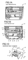
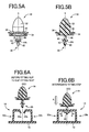
- FIGs. 1A to 1C are views showing a vehicle door trim 10 to which the first embodiment of the invention is applied.
- FIG. 1A is a view schematically showing an outer face of the vehicle door trim 10, that is, a vehicle compartment-side face of the vehicle door trim 10.
- FIG. 1B is a view schematically showing an inner face of the vehicle door trim 10, which is on the opposite side of the outer face.
- FIG. 1C is a perspective view showing an IC portion in FIG. 1B viewed from a direction of an arrow A.
- the vehicle door trim 10 corresponds to a trim board, and is made of synthetic resin material and formed as a single-piece member. Multiple (eight, in FIG.
- clip fitting seats 14 are formed integrally with an outer periphery portion of an inner face 12 that is located inside of a door (on the outer side of a vehicle compartment).
- Clips 16 are fastened to the clip fitting seats 14.
- the vehicle door trim 10 is fixed to the inner panel 18.
- the inner panel 18 corresponds to a vehicle body-side member.
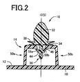
- FIG. 2 is an enlarged cross-sectional view showing the IC portion taken along the line II-II in FIG 1C .
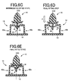
- FIGs. 4A to 4C are views showing the clip fitting seat 14 to which the clip 16 has not been fastened.
- FIGs. 5A and 5B are views showing only the clip 16.
- FIG. 4A is a perspective view corresponding to FIG. 1C
- FIG. 4B is a cross-sectional view corresponding to FIG. 2 , that is, an enlarged cross-sectional view showing the clip fitting seat 14 taken along the line IVB-IVB in FIG. 4A
- FIG. 4A is a perspective view corresponding to FIG. 1C
- FIG. 4B is a cross-sectional view corresponding to FIG. 2 , that is, an enlarged cross-sectional view showing the clip fitting seat 14 taken along the line IVB-IVB in FIG. 4A
- FIG. 4C is a plain view showing a portion near a fitting axis O viewed from a direction in which the clip 16 is fastened to the clip fitting seat 14 (hereinafter, referred to as "fastening direction" where appropriate) (viewed from above the clip fitting seat 14 in FIG. 4B ).
- FIG 5A is a perspective view showing the clip 16 viewed from a point that is slightly oblique to and above the clip 16.
- FIG. 5B is a longitudinal cross-sectional view of the clip 16, which includes a central axis S.
- the clip 16 has a first projection 30 and a second projection 32 that are aligned along the central axis S so as to extend in opposite directions, that is, extend outward.
- a first seating portion 34 which is large-diameter flange like and which is seated in the clip fitting seat 14, and a second seating portion 36, which is large-diameter flange like and which is seated in the inner panel 18, are formed between the first projection 30 and the second projection 32.
- the first projection 30, the second projection 32, the first seating portion 34 and the second seating portion 36 are made of synthetic resin material and formed integrally with each other.
- the first projection 30 has a small-diameter portion 40, a constricted portion 42 that is smaller in diameter than the small-diameter portion 40, a large-diameter portion 44 that is larger in diameter than the small-diameter portion 40, and a small-diameter fitted portion 46 formed between the large-diameter portion 44 and the first seating portion 34, which are formed concentrically with each other and which are located in this order from a tip end of the first projection 30 in a direction in which the first projection 30 is pushed into the clip fitting seat 14.
- the first projection 30 is fastened to the clip fitting seat 14 by being pushed into the clip fitting seat 14 in the fastening direction that is substantially perpendicular to the vehicle door trim 10 (up-down direction in FIG. 4B ).
- the small-diameter portion 40 is formed in a tapered shape, as a whole, in such a manner that a diameter thereof is decreased toward a tip end.
- a large-diameter base end-side outer peripheral portion of the small-diameter portion 40 has a smooth arc shape in a cross section shown in FIG. 5B , and is connected to the small-diameter constricted portion 42.
- the large-diameter portion 44 has a tapered face 44t having a diameter that is decreased toward the constricted portion 42.
- the fitted portion 46 is formed in a shape of a column having a predetermined diameter D.
- the fitted portion 46 has a predetermined length so that the clip 16 is integrally fastened to the clip fitting seat 14 in a certain posture when an upper end portion of the clip fitting seat 14 is elastically clamped between the large-diameter portion 44 and the first seating portion 34 as shown in FIG. 2 .
- the second projection 32 has a base end portion that is formed in a shape of a column that is larger in diameter than the fitting hole 20 of the inner panel 18, and a spindle-shaped tip end portion that projects from the base end portion and that has a smooth semi-elliptical shape in a cross-section in FIG. 5B .
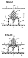
- the second projection 32 has a fitted portion 48 that is a constricted portion which is smaller in diameter than the fitting hole 20, and that is formed between the base end portion and the second seating portion 36. As shown in FIG. 3B , the second projection 32 is inserted into the fitting hole 20 from the tip end portion thereof.
- the inner panel 18 is located at the fitted portion 48 and the inner panel 18 is elastically clamped between the second projection 32 and the second seating portion 36.
- the clip 16 is fastened to the inner panel 18, and, consequently, the vehicle door trim 10 is fixed to the inner panel 18.
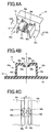
- the clip fitting seat 14 shown in FIGs. 4A and 4B has a pair of lug members 50a and 50b that are provided integrally with the vehicle door trim 10 so as to rise up in a direction substantially perpendicular to the vehicle door trim 10.
- the lug members 50a and 50b are formed integrally with the vehicle door trim 10 with the use of a slide die (draw back die) or the like.
- the lug members 50a and 50b are formed so as to be symmetric with respect to the fitting axis O that is substantially perpendicular to the vehicle door trim 10.
- the lug members 50a and 50b have vertical plate portions 54a and 54b and the lateral plate portions 56a and 56b, respectively, and each of the lug members 50a and 50b has a substantially L-shaped cross section.
- the vertical plate portions 54a and 54b rise up from the inner face 12 of the vehicle door trim 10 in a direction substantially perpendicular to the inner face 12.
- the lateral plate portions 56a and 56b extend from upper ends of the vertical plate portions 54a and 54b bent in a direction substantially perpendicular to the vertical plate portions 54a and 54b in such a manner that end portions of the lateral plate portions 56a and 56b face each other.
- the end portions of the lateral plate portions 56a and 56b, which face each other, are apart from each other by a small clearance g, which is smaller than the small-diameter portion 40.
- the end portions are stepped portions or crank-shaped portions that are formed by bending to recess the end portions of the lateral plate portions 56a and 56b toward the vehicle door trim 10.
- the formed stepped portions are used as latch lugs 58a and 58b.
- the small-diameter portion 40 shown in FIG. 4C indicates the maximum diameter of the small-diameter portion 40, and the clearance g is smaller than the maximum diameter of the small-diameter portion 40.
- the pair of latch lugs 58a and 58b has arc-shaped portions 59a and 59b centering on the fitting axis O and having a diameter d that is smaller than the small-diameter portion 40 and larger than the clearance g.
- the central axis S of the clip 16 coincides with the fitting axis O.
- the pair of lug members 50a and 50b is elastically deformed as indicated by arrows B in FIG. 6B .
- the distance between the pair of latch lugs 58a and 58b is enlarged in the lateral direction, whereby the small-diameter portion 40 is permitted to pass through between the latch lugs 58a and 58b.
- the upper end portions of the vertical plate portions 54a and 54b are elastically deformed in directions in which the upper end portions are further apart from each other, and corner portions, at which the vertical plate portions 54a and 54b and the lateral plate portions 56a and 56b are connected to each other, are elastically deformed in such a manner that the angles between the vertical plate portions 54a and 54b and the lateral plate portions 56a and 56b are reduced. In this way, the distance between the pair of latch lugs 58a and 58b is enlarged while the pair of latch lugs 58a and 58b is deformed so as to bend toward the vehicle door trim 10.
- the clip 16 is positioned in an intermediate fastened state where the pair of latch lugs 58a and 58b is located at the constricted portion 42 and clamped between the small-diameter portion 40 and the large-diameter portion 44 as shown in FIG. 6C .
- the distance between the small-diameter portion 40 and the large-diameter portion 44 is set to a value at which the clip 16 is positioned without wobbling when the latch lugs 58a and 58b are clamped between the small-diameter portion 40 and the large-diameter portion 44 of the clip 16.
- Partially tapered holding faces 60a and 60b (see FIGs. 4A to 4C ), which correspond to the tapered face 44t formed in the large-diameter portion 44, are formed in upper faces of the latch lugs 58a and 58b, respectively.
- the clip 16 When the holding faces 60a and 60b are pushed against the tapered face 44t and brought into surface-contact with the tapered face 44t in the intermediate fastened state, the clip 16 is positioned so as to take a certain posture in which the central axis S of the clip 16 substantially coincides with the fitting axis O.
- the clip 16 is positioned in a final fastened state where the pair of latch lugs 58a and 58b is located at the fitted portion 46 and the latch lugs 58a and 58b and the lateral plate portions 56a and 56b are located between the large-diameter portion 44 and the first seating portion 34 as shown in FIG. 6E .
- the large-diameter portion 44 is larger in diameter than the small-diameter portion 40, the lug members 50a and 50b need to be elastically deformed by a larger amount to permit the large-diameter portion 44 to pass through between the latch lugs 58a and 58b. Therefore, a larger pushing force (higher fastening load) is required in the final fastening step in FIG.
- the clip 16 is fastened more firmly to the clip fitting seat 14 with higher fastening strength in the final fastened state than in the intermediate fastened state.
- the first seating portion 34 that is larger in diameter than the large-diameter portion 44 is pushed against and tightly fastened to upper faces of the lateral plate portions 56a and 56b, and the clip 16 is held in a certain posture in which the central axis S substantially coincides with the fitting axis O more stably than in the intermediate fastened state.
- the clip 16 is permitted to move by a predetermined distance, which makes it possible to absorb a location deviation (positioning error) that may occur when the multiple clips 16 are fastened to engage with in the fitting holes 20 of the inner panel 18.
- the clearance g may be set to a value smaller than the diameter D, when the clip 16 is positioned.
- the multiple clip fitting seats 14 are formed on the inner face 12 of the vehicle door trim 10 in such a manner that the fitting axes O of the clip fitting seats 14 are substantially parallel to each other.
- the vehicle door trim 10 is not an entirely flat face and is partially curved or inclined, the clip fitting seats 14 are formed on the vehicle door trim 10 in postures in which the fitting axes O, that is, the fastening directions, are parallel to each other regardless of the shape of the vehicle door trim 10. Therefore, it is possible to fit the clips 16 to the clip fitting seats 14 in the certain fastening directions.
- FIGs. 6A to 6E are views illustrating basic fastening steps.
- the clip 16 is relatively pushed into the clip fitting seat 14 in the fastening direction indicated by the arrow A with a comparatively small force.
- the small-diameter portion 40 passes through between the latch lugs 58a and 58b while elastically deforming the pair of lug members 50a and 50b to enlarge the distance between the latch lugs 58a and 58b as indicated by the arrows B.
- the intermediate fastened state shown in FIG. 6C is achieved.
- the clip 16 which has been in the intermediate fastened state, is further pushed relatively into the clip fitting seat 14 with a large force in the fastening direction indicated by the arrow A as shown in FIG. 6D , the large-diameter portion 44 passes through between the latch lugs 58a and 58b while elastically deforming the pair of lug members 50a and 50b by a large amount to enlarge the distance between the latch lugs 58a and 58b as indicated by the arrows B.
- the final fastened state shown in FIG. 6E is achieved. It is possible to automatically perform both of the fastening steps in FIGs.
- the clips 16 may be manually fastened one by one to the clip fitting seats 14 in the intermediate fastening step in FIG. 6B , and the clips 16 may be automatically fastened to the multiple clip fitting seats 14 with the use of a fastening machine that uses, for example, a hydraulic cylinder in the final fastening step in FIG. 6D .
- FIGs. 7A and 7B show a case where both of the fastening steps in FIGs. 6B and 6D are automatically performed with the use of a fastening machine.
- FIG. 7A shows the intermediate fastening step
- FIG. 7B shows the final fastening step.
- the vehicle door trim 10 placed on a lower die 63 of a molding machine 62 which is used to form the vehicle door trim 10 and the multiple clip fitting seats 14 integrally with each other, is lifted and moved to an intermediate fastening site by a molded component removing robot 64.
- the molded component removing robot 64 has a removing attachment 66 to which, for example, an suction device is fitted.
- the clips 16 are prepared to be placed at locations corresponding to the multiple clip fitting seats 14, and a supply feeder 68, for example, an air cylinder is provided.
- the clips 16 are pushed upward one by one by the supply feeder 68 and fastened to the clip fitting seats 14 in the intermediate fastened state.
- the vehicle door trim 10 where the clips 16 are fastened to the multiple clip fitting seats 14 in the intermediate fastened state, is placed on a base 70 in a posture in which the clips 16 face upward.
- a pushing machine 72 for example, a hydraulic cylinder
- the clips 16 come into contact cylindrical pushing jigs 74 that are arranged above the clip fitting seats 14.
- the clips 16 are simultaneously pushed relatively into the clip fitting seats 14 and placed in the final fastened state.
- a pushing machine 72 for example, a press machine is preferably used.
- the small-diameter portion 40, the constricted portion 42, the large-diameter portion 44, and the fitted portion 46 are concentrically formed in the first projection 30 of the clip 16 in this order from the tip end of the first projection 30 in the fastening direction.
- the small-diameter portion 40 is engaged with the pair of latch lugs 58a and 58b formed in the clip fitting seats 14 as shown in FIG 6B .
- the small-diameter portion 40 passes through between the latch lugs 58a and 58b while elastically enlarging the distance between the latch lugs 58a and 58b.
- the intermediate fastened state where the latch lugs 58a and 58b are located at the constricted portion 42 is achieved as shown in FIG. 6C .
- the large-diameter portion 44 passes through between the pair of latch lugs 58a and 58b while elastically enlarging the distance between the latch lugs 58a and 58b as shown in FIG. 6D .
- the final fastened state where the latch lugs 58a and 58b are located at the fitted portion 46 is achieved as shown in FIG. 6E .
- the small-diameter portion 40 that is located at the tip end of the first projection 30 is smaller in diameter than the large-diameter portion 44, it is possible to relatively easily push the clip 16 into the clip fitting seat 14 in the intermediate fastening step. Therefore, the intermediate fastened state is easily achieved, for example, manually.
- the large-diameter portion 44 that is larger in diameter than the small-diameter portion 40 need to pass through between the latch lugs 58a and 58b. Therefore, the clip 16 is pushed with a relatively large pushing force (at high fastening load) in the final fastening step.
- the clip fastening structure With the clip fastening structure according to the first embodiment, it is possible to fit the clip 16 to the clip fitting seat 14 in the intermediate fastened state, and the clip 16 is pushed in the fastening direction, which is parallel to the fitting axis O that is substantially perpendicular to the vehicle door trim 10, to be fastened to the clip fitting seat 14. Therefore, even if the multiple clip fitting seats 14 are formed, the clips 16, which have been fastened to the clip fitting seats 14 in the intermediate fastened state, are simultaneously pushed into the clip fitting seats 14 by the single pushing machine 72, for example, in the final fastening step shown in FIG. 7B to achieve the final fastened state. Therefore, it is possible to increase the efficiency of the clip fastening work, and to automatically perform the clip fastening work.
- the intermediate fastening step it is possible to automatically fit the clips 16 to the multiple clip fitting seats 14 in the intermediate fastened state with the use of the molded component removing robot 64 and the supply feeder 68, for example, as in the intermediate fastening step in FIG. 7A .
- the large-diameter portion 44 of the first projection 30 of the clip 16 has the tapered face 44t having the diameter that is decreased toward the constricted portion 42, and the pair of latch lugs 58a and 58b has the partially tapered holding faces 60a and 60b, which conform to the tapered face 44t.
- the tapered face 44t of the large-diameter portion 44 is pushed against and brought into surface-contact with the holding faces 60a and 60b of the latch lugs 58a and 58b, the clip 16 is positioned so as to take a certain posture.
- the posture of the clip 16 in the intermediate fastened state is stabilized. Therefore, when the clip 16 is further pushed to be placed in the final fastened state, it is possible to prevent product failure, which may be caused if the clip 16 tips over. As a result, the production yield is improved.
- the clip fitting seat 14 is formed of the pair of lug members 50a and 50b rising up from the vehicle door trim 10, and the pair of latch lugs 58a and 58b is formed at the upper end portions of the lug members 50a and 50b so as to face each other.
- the small-diameter portion 40 and the large-diameter portion 44 of the first projection 30 are permitted to pass through between the latch lugs 58a and 58b due to elastic deformation of the pair of lug members 50a and 50b.
- the stiffness of the latch lugs 58a and 58b can be higher so that the clip 16 is more firmly fastened to the clip fitting seat 14 with higher fastening strength than when, for example, only the latch lugs 58a and 58b, which are part of the lug members 50a and 50b, are elastically deformed.
- the pair of lug members 50a and 50b is formed of the vertical plate portions 54a and 54b that rise up from the vehicle door trim 10 so as to parallel to each other, and the lateral plate portions 56a and 56b that extend from the upper end portions of the vertical plate portions 54a and 54b bent in the direction substantially perpendicular to the vertical plate portions 54a and 54b in such a manner that the end portions of the lateral plate portions 56a and 56b face each other.
- the end portions of the lateral plate portions 56a and 56b are the stepped portions that are used as the latch lugs 58a and 58b.
- the arc-shaped portions 59a and 59b which are centering on the fitting axis O and having the predetermined diameter d, are formed in end portions of the pair of latch lugs 58a and 58b. Due to the arc-shaped portions 59a and 59b, the clip 16 is fastened to the vehicle door trim 10 in such a manner that the central axis S of the clip 16 coincides with the fitting axis O at high accuracy. As a result, it is possible to more easily perform the work for fastening the vehicle door trim 10 to the inner panel 18 via the clip 16.
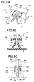
- FIGs. 8A to 8C are views showing a clip fitting seat according to a second embodiment, and correspond to FIGs. 4A to 4C , respectively.
- FIGs. 9A to 9E are views illustrating steps for fastening the clip 16 to a clip fitting seat 80 in FIG. 8 , and correspond to FIGs. 6A to 6E , respectively.
- the clip fitting seat 80 has a pair of lug members 82a and 82b extending from the vehicle door trim 10 and formed integrally with the vehicle door trim 10.
- the lug members 82a and 82b are formed integrally with the vehicle door trim 10, and formed so as to be symmetric with respect to the fitting axis O that is substantially perpendicular to the vehicle door trim 10.
- the lug members 82a and 82b have vertical plate portions 84a and 84b and lateral plate portions 86a and 86b, respectively.
- the vertical plate portions 84a and 84b rise up from the inner face 12 of the vehicle door trim 10.
- the lateral plate portions 86a and 86b extend from upper ends of the vertical plate portions 84a and 84b bent in opposite directions that are substantially perpendicular to the vertical plate portions 84a and 84b, respectively.
- Each of the lug members 82a and 82b has a substantially L-shaped cross section as a whole.
- the vertical plate portions 84a and 84b are bent at middle portions in such a manner that upper portions of the vertical plate portions 84a and 84b are parallel to each other and substantially perpendicular to the vehicle door trim and lower portions of the vertical plate portions 84a and 84b are oblique to the upper portions.
- Base end portions of the lateral plate portions 86a and 86b, that are close to each other, that is, the upper end portions of the vertical plate portions 84a and 84b are apart from each other by the clearance g which is smaller than the diameter (maximum diameter) of the small-diameter portion 40 of the clip 16.
- a pair of latch lugs 88a and 88b is formed in the base end portions of the lateral plate portions 86a and 86b, that is, the upper end portions of the vertical plate portions 84a and 84b, which face each other.
- the pair of latch lugs 88a and 88b has arc-shaped portions 89a and 89b centering on the fitting axis O and having the diameter d that is smaller than the small-diameter portion 40 and larger than the clearance g.
- the central axis S of the clip 16 coincides with the fitting axis O.
- the pair of lug members 82a and 82b is elastically deformed so as to be further apart from each other in right and left direction as indicated by arrows C in FIG 9B .
- the distance between the pair of latch lugs 88a and 88b is enlarged in the lateral direction, whereby the small-diameter portion 40 is permitted to pass through between the latch lugs 88a and 88b.
- the clip 16 is positioned in an intermediate fastened state where the pair of latch lugs 88a and 88b is located at the constricted portion 42 and clamped between the small-diameter portion 40 and the large-diameter portion 44 as shown in FIG. 9C .
- the clip 16 When the holding faces 90a and 90b are pushed against the tapered face 44t and brought into surface-contact with the tapered face 44t in the intermediate fastened state, the clip 16 is positioned so as to take a certain posture in which the central axis S of the clip 16 substantially coincides with the fitting axis O.
- the clip 16 is positioned in a final fastened state where the pair of latch lugs 88a and 88b is located at the fitted portion 46 and the latch lugs 88a and 88b and the lateral plate portions 86a and 86b are located between the large-diameter portion 44 and the first seating portion 34 as shown in FIG. 9E . Because the large-diameter portion 44 is larger in diameter than the small-diameter portion 40, the lug members 82a and 82b need to be elastically deformed by a larger amount to permit the large-diameter portion 44 to pass through between the latch lugs 88a and 88b.
- the clip 16 has the small-diameter portion 40, the constricted portion 42, the large-diameter portion 44, the fitted portion 46, the first seating portion 34, etc., and has substantially the same structure as that in the first embodiment. However, a diameter and an axial length of each portion are set appropriately based on a required strength, dimensions of the latch lugs 88a and 88b, etc.
- Through-holes 92a and 92b are formed in portions of the vertical plate portions 84a and 84b of the pair of lug members 82a and 82b, which are immediately below the latch lugs 88a and 88b.
- the small-diameter portion 40 or the large-diameter portion 44 which has passed through between the latch lugs 88a and 88b while elastically deforming the vertical plate portions 84a and 84b in such a manner that the vertical plate portions 84a and 84b are further apart from each other, is latched with upper edges of the through-holes 92a and 92b so as to be prevented from being removed.
- FIG. 10 is a side view showing the clip 16 and the clip fitting seat 80 viewed in the direction indicated by an arrow X in FIG. 9E .
- the clearance g may be set to a value smaller than the diameter D, when the clip 16 is positioned.
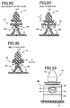
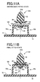
- a clip fitting seat 100 in FIGs. 11A and 11B differs from the clip fitting seat 14 in the first embodiment in that a pair of latch lugs (first pair of latch lugs) 102a and 102b, which are relatively small, is formed at positions above the pair of latch lugs (second pair of latch lugs) 58a and 58b by a predetermined distance.
- a first projection 106 of a clip 104 has the large-diameter portion 44 and the fitted portion 46, but does not have the small-diameter portion 40 and the constricted portion 42.
- the pair of lug members 50a and 50b is elastically deformed so as to be further apart from each other in the lateral direction and the distance between the latch lugs 102 and 102b is enlarged. Then, the large-diameter portion 44 passes through between the latch lugs 102a and 102 and is located between the pair of latch lugs 58a and 58b and the pair of latch lugs 102a and 102b. As a result, an intermediate fastened state shown in FIG. 11A is achieved.
- the large-diameter portion 44 is elastically clamped between the pair of latch lugs 58a and 58b and the pair of latch lugs 102a and 102b, and the tapered face 44t and the holding faces 60a and 60b are brought into the surface-contact with each other.
- the clip 104 is positioned so as to take a certain posture in which the central axis S and the fitting axis O substantially coincide with each other.
- the large-diameter portion 44 elastically deforms the pair of lug members 50a and 50b in such a manner that the distance between the lower latch lugs 58a and 58b is enlarged.
- the large-diameter portion 44 is permitted to pass through between the latch lugs 58a and 58b. As a result, as shown in FIG.
- the clip 104 is placed in a final fastened state where the latch lugs 58a and 58b have climbed over the large diameter portion 44, are located at the fitted portion 46, and engaged with the upper face of the large-diameter portion 44, and the first seating portion 34 is seated on the upper faces of the lateral plate portions 56a and 56b, as in the first embodiment.
- the latch lugs 102a and 102b, with which the first projection 106 is first engaged have small areas at which the latch lugs 102a and 102b are engaged with the large-diameter portion 44 (areas at which the latch lugs 102a and 102b overlap with the large-diameter portion 44 viewed in the fastening direction), and have low fastening load.
- the latch lugs 58a and 58b have large areas, at which the latch lugs 58a and 58b are engaged with the large-diameter portion 44, and have high fastening load.
- the same effects as those in the first embodiment are obtained.
- the first projection has an engagement portion (34, 40, 42, 44, 46) having a diameter that locally increases and decreases in a predetermined fastening direction that is substantially perpendicular to the trim board and the clip fitting seat has multiple latch lugs (58a, 58b, 88a, 88b, 102a, 102b) that are used to position the clip and elastically deformed in such a manner that a distance between the latch lugs is enlargeable as the engagement portion is engaged with the latch lugs, so that the first projection
Landscapes
- Engineering & Computer Science (AREA)
- General Engineering & Computer Science (AREA)
- Mechanical Engineering (AREA)
- Connection Of Plates (AREA)
- Insertion Pins And Rivets (AREA)
- Vehicle Interior And Exterior Ornaments, Soundproofing, And Insulation (AREA)
- Snaps, Bayonet Connections, Set Pins, And Snap Rings (AREA)
Applications Claiming Priority (1)
| Application Number | Priority Date | Filing Date | Title |
|---|---|---|---|
| JP2009191761A JP5059817B2 (ja) | 2009-08-21 | 2009-08-21 | トリムボードのクリップ組付構造、クリップ、およびクリップ組付方法 |
Publications (2)
| Publication Number | Publication Date |
|---|---|
| EP2287474A2 true EP2287474A2 (de) | 2011-02-23 |
| EP2287474A3 EP2287474A3 (de) | 2015-09-09 |
Family
ID=43126974
Family Applications (1)
| Application Number | Title | Priority Date | Filing Date |
|---|---|---|---|
| EP10173241.0A Withdrawn EP2287474A3 (de) | 2009-08-21 | 2010-08-18 | Struktur zur Befestigung eines Clips an einer Innenausstattungstafel, Clip und Clipbefestigungsverfahren |
Country Status (4)
| Country | Link |
|---|---|
| US (1) | US8584325B2 (de) |
| EP (1) | EP2287474A3 (de) |
| JP (1) | JP5059817B2 (de) |
| CN (1) | CN101994736B (de) |
Cited By (1)
| Publication number | Priority date | Publication date | Assignee | Title |
|---|---|---|---|---|
| DE102014211805A1 (de) | 2014-06-19 | 2015-12-24 | Faurecia Innenraum Systeme Gmbh | Verfahren und System zum Entnehmen eines flexiblen Formteils aus einem Formwerkzeug |
Families Citing this family (28)
| Publication number | Priority date | Publication date | Assignee | Title |
|---|---|---|---|---|
| WO2011068769A1 (en) * | 2009-12-01 | 2011-06-09 | Illinois Tool Works Inc. | Panel connection snap assembly |
| US20180185970A1 (en) * | 2011-08-09 | 2018-07-05 | Randy Simmons | Assembly, kit and method for securing a covering to an air intake face |
| US9878772B2 (en) * | 2012-01-10 | 2018-01-30 | Gulfstream Aerospace Corporation | Mounting assembly and method for mounting a sound-deadening body to a fuselage of an aircraft |
| WO2013136390A1 (ja) * | 2012-03-12 | 2013-09-19 | 株式会社パイオラックス | 付勢装置 |
| FR2992035B1 (fr) * | 2012-06-15 | 2014-06-20 | Renault Sa | Elements male et femelle pour l'assemblage par clippage de deux pieces en materiau polymere et assemblage correspondant |
| US9291182B2 (en) * | 2012-07-17 | 2016-03-22 | Ford Global Technologies, Llc | Vehicle attachment system having a domed-head fastener |
| JP2014043687A (ja) * | 2012-08-24 | 2014-03-13 | Sumitomo Kinzoku Kozan Siporex Kk | パネル取付金具及びパネル取付方法 |
| CN107600613A (zh) * | 2015-07-22 | 2018-01-19 | 吴红平 | 一种可换标签的新型瓦楞纸箱 |
| JP6571021B2 (ja) * | 2016-02-03 | 2019-09-04 | カルソニックカンセイ株式会社 | 車両用内装構造 |
| CN105782642A (zh) * | 2016-02-04 | 2016-07-20 | 无锡祥生医学影像有限责任公司 | 医疗器械外壳部件间的连接结构 |
| CN105583755A (zh) * | 2016-03-11 | 2016-05-18 | 上海球明标准件有限公司 | 一种用于过载保护的夹头 |
| CN106122207A (zh) * | 2016-07-01 | 2016-11-16 | 京信通信技术(广州)有限公司 | 一种快速固定型材与安装方法 |
| KR101796517B1 (ko) * | 2016-10-07 | 2017-11-10 | 주식회사 서연이화 | 차체 마운팅 파스너 결합구조 |
| US10124745B2 (en) * | 2017-01-06 | 2018-11-13 | GM Global Technology Operations LLC | Joining arrangement and method with molded stake and aperture |
| AU2017245280A1 (en) * | 2017-03-27 | 2018-10-11 | Zhenghui Gu | Multi-Buffering Safety Helmet |
| JP6844470B2 (ja) * | 2017-08-23 | 2021-03-17 | トヨタ自動車株式会社 | ドアトリム |
| US10351030B2 (en) | 2017-09-14 | 2019-07-16 | Ford Global Technologies, Llc | Seat trim retention system with asymmetrical retention force |
| CN109809047B (zh) * | 2017-11-22 | 2021-03-05 | 宋善慧 | 用于排出液体的容器 |
| US10363971B2 (en) * | 2017-11-27 | 2019-07-30 | Ford Global Technologies, Llc | Adaptable retainer |
| DE102017129298A1 (de) * | 2017-12-08 | 2019-06-13 | Khs Gmbh | Transportvorrichtung |
| CN108061257A (zh) * | 2017-12-08 | 2018-05-22 | 广州创维平面显示科技有限公司 | 一种背光模组及显示设备 |
| DE102018212692A1 (de) | 2018-07-30 | 2020-01-30 | Brose Fahrzeugteile Gmbh & Co. Kommanditgesellschaft, Bamberg | Türbaugruppe mit Befestigungselement und Montageverfahren |
| KR102085568B1 (ko) * | 2018-10-17 | 2020-03-06 | 주식회사 서연이화 | 도어 트림용 패스너 조립구조 |
| WO2021187291A1 (ja) * | 2020-03-16 | 2021-09-23 | テイ・エス テック株式会社 | ドア内装部材 |
| BE1027521B1 (fr) * | 2020-11-25 | 2022-02-11 | Shandong Longchang Intelligent Tech Co Ltd | Un dispositif de montage automatique pour les boutons-pression de panneaux intérieurs d'automobiles |
| US11661963B2 (en) * | 2021-04-08 | 2023-05-30 | GM Global Technology Operations LLC | Serviceable rotating magnetic pin |
| CN219937522U (zh) * | 2023-06-25 | 2023-10-31 | 泰科电子(苏州)有限公司 | 连接器部件和连接器 |
| WO2025009104A1 (ja) * | 2023-07-05 | 2025-01-09 | 日産自動車株式会社 | ドア構造及び取り付け部材 |
Citations (1)
| Publication number | Priority date | Publication date | Assignee | Title |
|---|---|---|---|---|
| JP2004183798A (ja) | 2002-12-04 | 2004-07-02 | Nifco Inc | クリップ及びこのクリップを利用したトリムボード取付構造 |
Family Cites Families (25)
| Publication number | Priority date | Publication date | Assignee | Title |
|---|---|---|---|---|
| SE439343B (sv) * | 1978-05-16 | 1985-06-10 | Itw Ltd | I ett stycke utfort ateranvendbart festorgan av plast, for anvendning pa platar med hal |
| JPS58130108U (ja) * | 1982-02-26 | 1983-09-02 | 河西工業株式会社 | 部材の取付け装置 |
| FR2589437B1 (fr) * | 1985-11-04 | 1988-06-10 | Flexico France Sarl | Dispositif de liaison entre deux feuilles de matiere plastique; sac equipe, pour sa fermeture, d'un tel dispositif |
| JPH0121209Y2 (de) * | 1985-12-13 | 1989-06-26 | ||
| JPS63166710U (de) * | 1987-04-20 | 1988-10-31 | ||
| JPH0297707A (ja) * | 1988-09-30 | 1990-04-10 | Kinugawa Rubber Ind Co Ltd | クリップ |
| DE4038159A1 (de) * | 1990-11-30 | 1992-06-11 | Raymond A & Cie | Zweiteiliger halteclip zur befestigung von schutz- oder zierleisten |
| US5469606A (en) * | 1993-02-11 | 1995-11-28 | Hansen; Arne | Clamp means for joining objects together |
| US5419606A (en) * | 1993-12-27 | 1995-05-30 | Ford Motor Company | Trim panel attaching pin with water seal |
| US5531499A (en) * | 1994-10-11 | 1996-07-02 | Ford Motor Company | Collapsible automotive trim panel boss |
| US6305892B1 (en) * | 1997-08-12 | 2001-10-23 | Zenith Electronics Corporation | Fastening system for speaker grilles |
| US6119306A (en) * | 1998-05-22 | 2000-09-19 | Southco, Inc. | Automotive deck lid bumper |
| DE29810437U1 (de) * | 1998-06-10 | 1998-10-01 | TRW Automotive Electronics & Components GmbH & Co. KG, 78315 Radolfzell | Verbindungselement zwischen einem Träger, insbesondere einem Karosserieteil eines Kraftfahrzeuges und einem Plattenelement |
| EP1057697B1 (de) * | 1999-06-02 | 2004-12-29 | Toyoda Gosei Co., Ltd. | Airbag- Kopfschutzvorrichtung mit Klammer zur Erleichterung der Montage-Demontage |
| DE60019816D1 (de) * | 2000-10-03 | 2005-06-02 | Itw Espana Sa | Vorrichtung zur befestigung einer platte und einer stützscheibe aneinander |
| DE20017376U1 (de) * | 2000-10-10 | 2001-02-15 | TRW Automotive Electronics & Components GmbH & Co. KG, 78315 Radolfzell | Vorrichtung zur Verbindung eines Trägers, insbesondere eines Karosserieteils eines Kraftfahrzeuges, mit einem Plattenelement, insbesondere einer Tür- oder Wandverkleidung |
| US6594870B1 (en) * | 2001-01-22 | 2003-07-22 | Johnson Controls Technology Company | Panel fastener |
| JP2003291860A (ja) * | 2002-04-05 | 2003-10-15 | Nippon Pop Rivets & Fasteners Ltd | 自動車の床裏のアンダーカバー取付装置 |
| US7114221B2 (en) * | 2003-01-17 | 2006-10-03 | Newfrey Llc | Two-piece interior trim retainer |
| KR100501490B1 (ko) * | 2003-09-24 | 2005-07-18 | 현대자동차주식회사 | 도어트림 장착 구조 |
| DE10358683B4 (de) * | 2003-12-12 | 2005-11-17 | A. Raymond & Cie | Vorrichtung zum Verbinden eines Trägerteils und eines Anbauteils |
| JP2005337312A (ja) * | 2004-05-25 | 2005-12-08 | Piolax Inc | 止め具 |
| JP4472456B2 (ja) * | 2004-08-05 | 2010-06-02 | 株式会社ニフコ | 留め具 |
| US7384210B2 (en) * | 2004-08-24 | 2008-06-10 | Dell Products L.P. | Method and apparatus for mounting a component in an information handling system |
| JP5243749B2 (ja) | 2007-08-09 | 2013-07-24 | 株式会社ニフコ | クリップ及び支持部材 |
-
2009
- 2009-08-21 JP JP2009191761A patent/JP5059817B2/ja not_active Expired - Fee Related
-
2010
- 2010-08-12 US US12/855,307 patent/US8584325B2/en not_active Expired - Fee Related
- 2010-08-18 EP EP10173241.0A patent/EP2287474A3/de not_active Withdrawn
- 2010-08-23 CN CN201010261303.0A patent/CN101994736B/zh not_active Expired - Fee Related
Patent Citations (1)
| Publication number | Priority date | Publication date | Assignee | Title |
|---|---|---|---|---|
| JP2004183798A (ja) | 2002-12-04 | 2004-07-02 | Nifco Inc | クリップ及びこのクリップを利用したトリムボード取付構造 |
Cited By (1)
| Publication number | Priority date | Publication date | Assignee | Title |
|---|---|---|---|---|
| DE102014211805A1 (de) | 2014-06-19 | 2015-12-24 | Faurecia Innenraum Systeme Gmbh | Verfahren und System zum Entnehmen eines flexiblen Formteils aus einem Formwerkzeug |
Also Published As
| Publication number | Publication date |
|---|---|
| US8584325B2 (en) | 2013-11-19 |
| CN101994736B (zh) | 2014-12-10 |
| EP2287474A3 (de) | 2015-09-09 |
| JP2011043209A (ja) | 2011-03-03 |
| JP5059817B2 (ja) | 2012-10-31 |
| CN101994736A (zh) | 2011-03-30 |
| US20110041299A1 (en) | 2011-02-24 |
Similar Documents
| Publication | Publication Date | Title |
|---|---|---|
| EP2287474A2 (de) | Struktur zur Befestigung eines Clips an einer Innenausstattungstafel, Clip und Clipbefestigungsverfahren | |
| US12214702B2 (en) | Clip for upholstery cover | |
| JP6851884B2 (ja) | クリップ | |
| US20140298962A1 (en) | Elastic averaging alignment system, method of making the same and cutting punch therefor | |
| JP5992494B2 (ja) | 一体型シートバック構造体 | |
| US20140369743A1 (en) | Elastic retaining assembly for matable components and method of assembling | |
| BR112017021368B1 (pt) | Luva de aperto e um processo para produção de uma luva de aperto | |
| CN114954154B (zh) | 座椅滑动装置以及弹簧构件的组装方法 | |
| US20080044255A1 (en) | Plastic clip for fastening an object to a stud and fastening arrangement using such clip | |
| KR101676600B1 (ko) | 모터 비히클용 시트 조정 장치의 드라이브 | |
| CN107635828A (zh) | 车辆座椅的导向套筒 | |
| US11772533B2 (en) | Seat upholstery clip | |
| JP5225244B2 (ja) | クリップ及びクリップ付きワイヤハーネス | |
| JP6617187B1 (ja) | 可動コネクタ | |
| JP2010173412A (ja) | 車両用内装材の取付構造 | |
| JP2012171587A (ja) | ベルト取付具及びベルト取付具の製造方法 | |
| AU2008332563B2 (en) | Structure and method for mounting seat for vehicle | |
| JP5396762B2 (ja) | ドアパネル取付用クリップ座を備えるドアトリム基材 | |
| JP2008223918A (ja) | アンカー | |
| US20140312643A1 (en) | Assist grip attachment structure | |
| KR101352285B1 (ko) | 자동차 시트의 아티큘레이션 라이닝용 하우징 및 그조립체의 제조 방법 | |
| JP2024052643A (ja) | ロック保持器 | |
| CN112823114B (zh) | 用于机动车辆的发动机托架 | |
| JP4842303B2 (ja) | エアバッグ装置 | |
| JP4779965B2 (ja) | 部材取付け構造 |
Legal Events
| Date | Code | Title | Description |
|---|---|---|---|
| PUAI | Public reference made under article 153(3) epc to a published international application that has entered the european phase |
Free format text: ORIGINAL CODE: 0009012 |
|
| AK | Designated contracting states |
Kind code of ref document: A2 Designated state(s): AL AT BE BG CH CY CZ DE DK EE ES FI FR GB GR HR HU IE IS IT LI LT LU LV MC MK MT NL NO PL PT RO SE SI SK SM TR |
|
| AX | Request for extension of the european patent |
Extension state: BA ME RS |
|
| 17P | Request for examination filed |
Effective date: 20110922 |
|
| PUAL | Search report despatched |
Free format text: ORIGINAL CODE: 0009013 |
|
| AK | Designated contracting states |
Kind code of ref document: A3 Designated state(s): AL AT BE BG CH CY CZ DE DK EE ES FI FR GB GR HR HU IE IS IT LI LT LU LV MC MK MT NL NO PL PT RO SE SI SK SM TR |
|
| AX | Request for extension of the european patent |
Extension state: BA ME RS |
|
| RIC1 | Information provided on ipc code assigned before grant |
Ipc: F16B 5/12 20060101AFI20150731BHEP Ipc: F16B 21/08 20060101ALN20150731BHEP Ipc: F16B 21/07 20060101ALI20150731BHEP Ipc: B60R 13/02 20060101ALI20150731BHEP |
|
| STAA | Information on the status of an ep patent application or granted ep patent |
Free format text: STATUS: THE APPLICATION HAS BEEN WITHDRAWN |
|
| 18W | Application withdrawn |
Effective date: 20170126 |