EP2275620B1 - Floorboards - Google Patents
Floorboards Download PDFInfo
- Publication number
- EP2275620B1 EP2275620B1 EP10180452.4A EP10180452A EP2275620B1 EP 2275620 B1 EP2275620 B1 EP 2275620B1 EP 10180452 A EP10180452 A EP 10180452A EP 2275620 B1 EP2275620 B1 EP 2275620B1
- Authority
- EP
- European Patent Office
- Prior art keywords
- joint
- floorboards
- board
- strip
- locking
- Prior art date
- Legal status (The legal status is an assumption and is not a legal conclusion. Google has not performed a legal analysis and makes no representation as to the accuracy of the status listed.)
- Expired - Lifetime
Links
Images

Classifications
-
- E—FIXED CONSTRUCTIONS
- E04—BUILDING
- E04F—FINISHING WORK ON BUILDINGS, e.g. STAIRS, FLOORS
- E04F15/00—Flooring
- E04F15/02—Flooring or floor layers composed of a number of similar elements
- E04F15/10—Flooring or floor layers composed of a number of similar elements of other materials, e.g. fibrous or chipped materials, organic plastics, magnesite tiles, hardboard, or with a top layer of other materials
- E04F15/102—Flooring or floor layers composed of a number of similar elements of other materials, e.g. fibrous or chipped materials, organic plastics, magnesite tiles, hardboard, or with a top layer of other materials of fibrous or chipped materials, e.g. bonded with synthetic resins
-
- E—FIXED CONSTRUCTIONS
- E04—BUILDING
- E04F—FINISHING WORK ON BUILDINGS, e.g. STAIRS, FLOORS
- E04F2201/00—Joining sheets or plates or panels
- E04F2201/01—Joining sheets, plates or panels with edges in abutting relationship
- E04F2201/0107—Joining sheets, plates or panels with edges in abutting relationship by moving the sheets, plates or panels substantially in their own plane, perpendicular to the abutting edges
- E04F2201/0115—Joining sheets, plates or panels with edges in abutting relationship by moving the sheets, plates or panels substantially in their own plane, perpendicular to the abutting edges with snap action of the edge connectors
-
- E—FIXED CONSTRUCTIONS
- E04—BUILDING
- E04F—FINISHING WORK ON BUILDINGS, e.g. STAIRS, FLOORS
- E04F2201/00—Joining sheets or plates or panels
- E04F2201/01—Joining sheets, plates or panels with edges in abutting relationship
- E04F2201/0153—Joining sheets, plates or panels with edges in abutting relationship by rotating the sheets, plates or panels around an axis which is parallel to the abutting edges, possibly combined with a sliding movement
-
- E—FIXED CONSTRUCTIONS
- E04—BUILDING
- E04F—FINISHING WORK ON BUILDINGS, e.g. STAIRS, FLOORS
- E04F2201/00—Joining sheets or plates or panels
- E04F2201/02—Non-undercut connections, e.g. tongue and groove connections
- E04F2201/026—Non-undercut connections, e.g. tongue and groove connections with rabbets, e.g. being stepped
-
- E—FIXED CONSTRUCTIONS
- E04—BUILDING
- E04F—FINISHING WORK ON BUILDINGS, e.g. STAIRS, FLOORS
- E04F2201/00—Joining sheets or plates or panels
- E04F2201/04—Other details of tongues or grooves
- E04F2201/041—Tongues or grooves with slits or cuts for expansion or flexibility
-
- E—FIXED CONSTRUCTIONS
- E04—BUILDING
- E04F—FINISHING WORK ON BUILDINGS, e.g. STAIRS, FLOORS
- E04F2201/00—Joining sheets or plates or panels
- E04F2201/04—Other details of tongues or grooves
- E04F2201/042—Other details of tongues or grooves with grooves positioned on the rear-side of the panel
-
- E—FIXED CONSTRUCTIONS
- E04—BUILDING
- E04F—FINISHING WORK ON BUILDINGS, e.g. STAIRS, FLOORS
- E04F2201/00—Joining sheets or plates or panels
- E04F2201/04—Other details of tongues or grooves
- E04F2201/044—Other details of tongues or grooves with tongues or grooves comprising elements which are not manufactured in one piece with the sheets, plates or panels but which are permanently fixedly connected to the sheets, plates or panels, e.g. at the factory
- E04F2201/045—Other details of tongues or grooves with tongues or grooves comprising elements which are not manufactured in one piece with the sheets, plates or panels but which are permanently fixedly connected to the sheets, plates or panels, e.g. at the factory wherein the elements are made of wood
-
- E—FIXED CONSTRUCTIONS
- E04—BUILDING
- E04F—FINISHING WORK ON BUILDINGS, e.g. STAIRS, FLOORS
- E04F2201/00—Joining sheets or plates or panels
- E04F2201/04—Other details of tongues or grooves
- E04F2201/044—Other details of tongues or grooves with tongues or grooves comprising elements which are not manufactured in one piece with the sheets, plates or panels but which are permanently fixedly connected to the sheets, plates or panels, e.g. at the factory
- E04F2201/046—Other details of tongues or grooves with tongues or grooves comprising elements which are not manufactured in one piece with the sheets, plates or panels but which are permanently fixedly connected to the sheets, plates or panels, e.g. at the factory wherein the elements are made of metal
-
- E—FIXED CONSTRUCTIONS
- E04—BUILDING
- E04F—FINISHING WORK ON BUILDINGS, e.g. STAIRS, FLOORS
- E04F2201/00—Joining sheets or plates or panels
- E04F2201/05—Separate connectors or inserts, e.g. pegs, pins, keys or strips
- E04F2201/0517—U- or C-shaped brackets and clamps
Definitions
- the invention generally relates to a locking system for providing mechanical joining of floorboards. More specifically, the invention concerns an improvement of a locking system of the type described and shown in WO 94/26999 .
- the invention also relates to a floorboard provided with such a locking system. According to one more aspect of the invention, a floorboard with different designs of the locking system on long side and short side is provided.
- the invention is particularly suited for mechanical joining of thin floating floorboards, such as laminate and parquet flooring, and therefore the following description of prior art and the objects and features of the invention will be directed to this field of application, in particular rectangular floorboards that are joined on long sides as well as short sides.
- the features distinguishing the invention concern in the first place parts of the locking system which are related to horizontal locking transversely of the joint edges of the boards.
- floorboards will be manufactured according to the inventive principles of also having locking means for mutual vertical locking of the boards.
- WO 94/26999 discloses a locking system for mechanical joining of building boards, especially floorboards.
- a mechanical locking system permits locking together of the boards both perpendicular to and in parallel with the principal plane of the boards on long sides as well as short sides.
- Methods for making such floorboards are described in SE 9604484-7 and SE 9604483-9 .
- the principles of designing and laying the floorboards as well as the methods for making the same that are described in the above three documents are applicable also to the present invention.
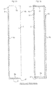
- a floorboard 1 of known design is shown from below and from above in Figs 3a and 3b , respectively.
- the board is rectangular and has a top side 2, an underside 3, two opposite long sides 4a, 4b which form joint edges, and two opposite short sides 5a, 5b which form joint edges.
- the board 1 has a planar strip 6 which is mounted at the factory and which extends horizontally from one long side 4a, the strip extending along the entire long side 4a and being made of a flexible, resilient aluminium sheet.
- the strip 6 can be mechanically fixed according to the illustrated embodiment, or fixed by means of glue or in some other fashion.
- Other strip materials can be used, such as sheet of some other metal, and aluminium or plastic sections.
- the strip 6 can be integrally formed with the board 1, for instance by some suitable working of the body of the board 1. The strip, however, is always integrated with the board 1, i.e.
- the width of the strip 6 can be about 30 mm and its thickness about 0.5 mm.
- a similar, although shorter strip 6' is arranged also along one short side 5a of the board 1.
- the edge side of the strip 4 facing away from the joint edge 4a is formed with a locking element 8 extending along the entire strip 6.
- the locking element 8 has an active locking surface 10 facing the joint edge 4a and having a height of e.g. 0.5 mm.
- the locking element 8 cooperates with a locking groove 14, which is formed in the underside 3 of the opposite long side 4b of an adjacent board 1'.
- the short side strip 6' is provided with a corresponding locking element 8', and the opposite short side 5b has a corresponding locking groove 14'.
- the board 1 is further along its one long side 4a and its one short side 5a formed with a laterally open recess 16.
- the recess 16 is defined downwards by the associated strip 6, 6'.
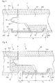
- Figs 1a-1c show how two such boards 1, 1' can be joined by downwards angling.
- Figs 2a-2c show how the boards 1, 1' can instead be joined by snap action.
- the long sides 4a, 4b can be joined by both methods whereas the short sides 5a, 5b - after laying of the first row - are normally joined after joining of the long sides and merely by snap action.
- the long side 4b of the new board 1' is pressed against the long side 4a of the previously laid board 1 according to Fig. 1a , so that the locking tongue 20 is inserted into the recess 16.
- the board 1' is then angled downwards to the subfloor 12 according to Fig. 1b .
- the locking tongue 20 completely enters the recess 16 while at the same time the locking element 8 of the strip 6 enters the locking groove 14.
- the upper part of the locking element 8 can be active and accomplish a guiding of the new board 1' towards the previously laid board 1.
- the boards 1, 1' are locked in both D1 direction and D2 direction, but may be displaced relative to each other in the longitudinal direction of the joint.
- Figs 2a-2c illustrate how also the short sides 5a and 5b of the boards 1, 1' can be mechanically joined in both D1 and D2 direction by the new board 1' being moved essentially horizontally towards the previously laid board 1. This can be carried out after the long side 4b of the new board 1' has been joined as described above.
- bevelled surfaces adjacent to the recess 16 and the locking tongue 20 cooperate so that the strip 6' is forced downwards as a direct consequence of the joining of the short sides 5a, 5b.
- the strip 6' snaps upwards as the locking element 8' enters the locking groove 14'.
- Norske Skog Flooring AS (licensee of Välinge Aluminium AB) introduced a laminate flooring with a mechanical joining system according to WO 94/29699 in January 1996 in connection with the Domotex fair in Hannover, Germany.
- This laminate flooring marketed under the trademark Alloc® is 7.6 mm thick, has a 0.6 mm aluminium strip 6 which is mechanically fixed to the tongue side and the active locking surface 10 of the locking element 8 has an inclination of about 70°-80° to the plane of the board.
- the joint edges are impregnated with wax and the underside is provided with underlay board which is mounted at the factory.
- the vertical joint is designed as a modified tongue-and-groove joint.
- the strips 6, 6' on long side and short side are largely identical, but slightly bent upwards to different degrees on long side and short side.
- the inclination of the active locking surface varies between long side and short side.
- the distance of the locking groove 14 from the joint edge is somewhat smaller on the short side than on the long side.
- the boards are made with a nominal play on the long side which is about 0.05-0.10 mm. This enables displacement of the long sides and bridges width tolerances of the boards. Boards of this brand have been manufactured and sold with zero play on the short sides, which is possible since the short sides need not be displaced in connection with the locking which is effected by snap action. Boards of this brand have also been made with more bevelled portions on the short side to facilitate snapping in according to Figs 2a-c above. It is thus known that the mechanical locking system can be designed in various ways and that long side and short side can be of different design.
- WO 97/47834 discloses a mechanical joining system which is essentially based on the above known principles. In the corresponding product which this applicant began to market in the latter part of 1997, biasing between the boards is strived for. This leads to high friction and difficulties in angling together and displacing the boards. This document also shows that the mechanical locking on the short side can be designed in a manner different from the long side.
- the strip is integrated with the body of the board, i.e. made in one piece with and of the same material as the body of the board.
- Mechanical joints are very suitable for joining not only laminate floorings, but also wood floorings and composite floorings.
- Such floorboards may consist of a large number of different materials in the surface, the core and the rear side, and as described above these materials can also be included in the strip of the joining system, the locking element on the strip, fixing surfaces, vertical joints etc.
- This solution involving an integrated strip leads to costs in the form of waste when the mechanical joint is being made.
- special materials, such as the aluminium strip 6 above can be glued or mechanically fixed to the floorboard to be included as components in the joining system. Different joint designs affect the costs to a considerable extent.
- a strip made of the same material as the body of the board and formed by working of the body of the board can in some applications be less expensive than an aluminium strip, especially for floorboards in lower price ranges. Aluminium, however, is more advantageous in respect of flexibility, resilience and displaceability as well as accuracy in the positioning of the locking element. Aluminium also affords the possibility of making a stronger locking element. If the same strength is to be achieved with a locking element of wood fibre, it must be wide with a large shearing surface, which results in a large amount of waste material in manufacture, or it must be reinforced with a binder. Depending on the size of the boards, working of, for instance, 10 mm of a joint edge may result in six times higher cost of waste per m 2 of floor surface along the long sides compared with the short sides.
- the present invention is based on the insight that the long sides and short sides can be optimised with regard to the specific locking functions that should be present in these joint edges.
- locking of the long side is, as a rule, carried out by downwards angling. Also a small degree of bending down of the strip during locking can take place, as will be described in more detail below. Thanks to this downwards bending together with an inclination of the locking element, the boards can be angled down and up again with very tight joint edges.
- the locking element along the long sides should also have a high guiding capability so that the long side of a new board in connection with downwards angling is pushed towards the joint edge of the previously laid board.
- the locking element should have a large guiding part.
- the boards should along their long sides, after being joined, be able to take a mutual position transversely of the joint edges where there is a small play between locking element and locking groove.
- the short side must have means which accomplish downwards bending of the strip in connection with lateral displacement.
- the strength requirement is also higher on the short side. Guiding and displaceability are less important.
- a locking system for mechanical joining of floorboards where immediately juxtaposed upper parts of two adjacent joint edges of two joined floorboards together define a joint plane perpendicular to the principal plane of the floor boards.
- the locking system comprises in a manner known per se a locking groove which is formed in the underside of and extends in parallel with the first joint edge at a distance from the joint plane, and a portion projecting from the lower part of the second joint edge and below the first joint edge and integrated with a body of the board, said projecting portion supporting at a distance from the joint plane a locking element cooperating with the locking groove and thus positioned entirely outside the joint plane seen from the side of the second joint edge, said projecting portion having a different composition of materials compared with the body of the board.
- the inventive locking system is characterised in that the projecting portion presents at least two horizontally juxtaposed parts, which are composed of different material compositions, and in that said at least two parts
- said at least two parts of the projecting portion are located at different distances from the joint plane.
- they may comprise an inner part closest to the joint plane and an outer part at a distance from the joint plane.
- the inner part and the outer part are preferably, but not necessarily, of equal length in the joint direction.
- a material other than that included in the body is thus included in the joining system, and in particular the outer part can be at least partially formed of a separate strip which is made of a material other than that of the body of the board and which is integrally connected with the board by being factory-mounted.
- the inner part can be formed at least partially of a worked part of the body of the board and partially of part of said separate strip.
- the separate strip can be attached to such a worked part of the board body.
- the strip can be located entirely outside said joint plane, but can also intersect the joint plane and extend under the joint edge to be attached to the body also inside the joint plane.
- This invention thus provides a kind of combination strip in terms of material, for example a projecting portion comprising an inner part with the material combination wood fibre/rear laminate/aluminium, and an outer part of aluminium sheet.
- the projecting part from three parts which are different in terms of material: an inner part closest to the joint plane, a central part and an outer part furthest away from the joint plane.
- the inner part and the outer part can possibly be equal in terms of material.
- the portion projecting outside the joint plane need not necessarily be continuous or unbroken along the joint edge.
- the projecting portion has a plurality of separate sections distributed along the joint edge. As an example, this can be accomplished by means of a separate strip with a continuous inner part and a toothed outer part, said strip being attachable to a part of the board body, said part being worked outside the joint plane.
- said at least two parts which differ in respect of at least one of the parameters material composition and material properties, are instead juxtaposed seen in the direction parallel with the joint edges.
- each strip type is optimised for a special function, such as strength and guiding in connection with laying.
- the strips can be made of different aluminium alloys and/or of aluminium having different states (for instance, as a result of different types of heat treatment).
- the projecting portion is instead formed in one piece with the body of the board and thus has the same material composition as the body of the board.
- This embodiment is characterised in that the projecting portion, as a direct consequence of machining of its upper side, presents at least two horizontally juxtaposed parts, which differ from each other in respect of at least one of the parameters material composition and material properties.
- these two parts can be located at different distances from the joint plane, and especially there may be three or more parts with different material composition and/or material properties.
- two such parts can be equal in respect of said parameters, but they may differ from a third.
- said two parts may comprise an inner part closest to the joint plane and an outer part at a distance from the joint plane. There may be further parts outside the outer part.
- an outer part can be formed of fewer materials than an inner part.
- the inner part may consist of wood fibre and rear laminate, whereas the outer part, by machining from above, consists of rear laminate only.
- the projecting portion may comprise - seen from the joint plane outwards - an inner part, an outer part and, outside the outer part, a locking element supported by the outer part. The locking element may differ from both inner and outer part in respect of said material parameters.
- the projecting portion may consist of three laminated layers, and therefore it is possible, by working from above, to provide a locking system which, counted from the top, has a relatively soft upper guiding part which need not have any particular strength, a harder central part which forms a strong active locking surface and absorbs shear forces in the locking element, and a lower part which is connected with the rest of the projecting portion and which can be thin, strong and resilient.
- Laminated embodiments can be suitable in such floorboards where the body of the board consists of, for instance, plywood or particle board with several layers. Corresponding layers can be found in the walls of the locking groove.
- the material properties can be varied by changing the direction of fibres in the layers.
- the material properties can be varied by using different chip dimensions and/or a binder in the different layers.
- the board body can generally consist of layers of different plastic materials.
- the term "projecting portion” relates to the part or parts of the board projecting outside the joint plane and having a function in the locking system in respect of supporting of locking element, strength, flexibility etc.
- An underlay of underlay board, foam, felt or the like can, for instance, be mounted even in the manufacture of the boards on the underside thereof.
- the underlay can cover the underside up to the locking element, so that the joint between the underlays will be offset relative to the joint plane F.
- an underlay is positioned outside the joint plane, it should thus not be considered to be included in the definition of the projecting portion in the appended claims.
- any thin material layers which remain after working from above should in the same manner not be considered to be included in the "projecting portion" in the cases where such layers do not contribute to the locking function in respect of strength, flexibility, etc.
- the same discussion applies to thin glue layers, binders, chemicals, etc. which are applied, for instance, to improve moisture proofing and strength.
- the projecting portion of a given joint edge for instance a long side, has at least two parts with different material compositions.
- a difference in materials may be considered to exist between the long sides and short sides of the board instead of within one and the same joint edge.
- a rectangular floorboard comprising a body and first and second locking means integrated with the body and adapted to provide a mechanical joining of adjacent joint edges of such floorboards along long sides and short sides, respectively, of the boards in a direction perpendicular to the respective joint edges and in parallel with the principal plane of the floorboards.
- the floorboard is characterised in that said first and second locking means differ in respect of at least one of the parameters material composition and material properties.
- said first and second locking means each comprise on the one hand a portion which projects from a joint edge and which at a distance from the joint edge supports a locking element and, on the other hand, a locking groove, which is formed in the underside of the body at an opposite joint edge for engaging such a locking element of an adjacent board.
- At least one of said locking means on the long side and the short side may comprise a separate element which is integrally fixed to the body of the board at the factory and is made of a material other than that included in the body of the board.
- the other locking means may comprise an element which is formed in one piece with the body of the board.
- the projecting portion being made of different materials and thus specially adaptable to the selected materials in the floorboard and the function and strength requirements that apply to the specific floorboard and that are specific for long side and short side.
- the long side and the short side being made of different materials or combinations of materials.
- the long side can have, for instance, an aluminium strip with high guiding capability and low friction whereas the short side can have a wood fibre strip. In other applications, the opposite is advantageous.
- the side may consist of, for instance, a plurality of different strips which are made of different aluminium alloys, have different thicknesses etc. and in which certain parts are intended to achieve high strength and others are intended to be used for guiding.
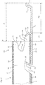
- FIG. 4-7 A first preferred embodiment of a floorboard 1 provided with a locking system according to the invention will now be described with reference to Figs 4-7 .
- the shown example also illustrates the aspect of the invention which concerns differently designed locking systems for long side and short side.
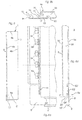
- Fig. 4 is a cross-sectional view of a long side 4a of the board 1.
- the body of the board 1 consists of a core 30 of, for instance, wood fibre which supports a surface laminate 32 on its front side and a balance layer 34 on its rear side.
- the board body 30-34 is rectangular with long sides 4a, 4b and short sides 5a, 5b.
- a separate strip 6 with a formed locking element 8 is mounted at the factory on the body 30-34, so that the strip 6 constitutes an integrated part of the completed floorboard 1.
- the strip 6 is made of resilient aluminium sheet.
- the aluminium sheet can have a thickness in the order of 0.6 mm and the floorboard a thickness in the order of 7 mm.
- the strip 6 is formed with a locking element 8, whose active locking surface 10 cooperates with a locking groove 14 in an opposite joint edge 4b of an adjacent board 1' for horizontal locking together of the boards 1, 1' transversely of the joint edge (D2).
- the joint edge 4a has a laterally open groove 36 and the opposite joint edge 4b has a laterally projecting tongue 38 (corresponding to the locking tongue 20), which in the joined state is received in the groove 36 ( Fig. 7c ).
- the free surface of the upper part 40 of the groove 36 has a vertical upper portion 41, a bevelled portion 42 and an upper abutment surface 43 for the tongue 38.
- the free surface of the lower part 44 of the groove 36 has a lower abutment surface 45 for the tongue 38, a bevelled portion 46 and a lower vertical portion 47.
- the opposite joint edge 4b (see Fig. 7a ) has an upper vertical portion 48, and the tongue 38 has an upper abutment surface 49, an upper bevelled portion 50, a lower bevelled portion 51 and a lower abutment surface 52.
- the two juxtaposed vertical upper portions 41 and 48 define a vertical joint plane F.
- the lower part 44 of the groove 36 is extended a distance outside the joint plane F.
- the joint edge 4a is in its underside formed with a continuous mounting groove 54 having a vertical lower gripping edge 56 and an inclined gripping edge 58.
- the gripping edges formed of the surfaces 46, 47, 56, 58 together define a fixing shoulder 60 for mechanical fixing of the strip 6.
- the fixing is carried out according to the same principle as in the prior-art board and can be carried out by means of the methods that are described in the above-mentioned documents.
- a continuous lip 62 of the strip 6 thus is bent round the gripping edges 56, 58 of the groove 54, while a plurality of punched tongues 64 are bent round the surfaces 46, 47 of the projecting portion 44.
- the tongues 64 and the associated punched holes 65 are shown in the broken-out view in Fig. 6a .
- the area P in Fig. 4 designates the portion of the board 1 which is positioned outside the joint plane 1.
- the portion P has two horizontally juxtaposed parts P1 and P2, which differ in respect of their material composition. More specifically, the inner part P1 is, closest to the joint plane F, formed partially of the strip 6 and partially of the worked part 44 of the body.
- the inner part P1 thus comprises the material combination aluminium + wood fibre core + rear laminate whereas the outer part P2 is a made of aluminium only.
- the corresponding portion outside the joint plane is made of aluminium only.
- this feature of the invention means that the cost of material can be reduced. Thanks to the fact that the fixing shoulder 60 is displaced towards the locking element 8 to such an extent that it is positioned at least partially outside the joint plane F, a considerable saving can be achieved in respect of the consumption of aluminium sheet. A saving in the order of 25% is possible.
- This embodiment is particularly advantageous in cheaper floorboards where waste of wood fibre as a result of machining of the body is preferred to a high consumption of aluminium sheet.
- the waste of material is limited thanks to the fact that the projecting portion can also be used as abutment surface for the tongue, which can then be made correspondingly narrower perpendicular to the joint plane with the ensuing reduced waste of material on the tongue side.
- This constructional change to achieve saving in material does not have a detrimental effect on the possibility of resilient vertical motion that must exist in the projecting portion P.
- the strength of the locking element 8 is not affected either.
- the outer part P2 of aluminium is still fully resilient in the vertical direction, and the short sides 5a, 5b can be snapped together according to the same principle as in Figs 2a-c .
- the locking element 8 is still made of aluminium and its strength is not reduced.
- the degree of resilience can be affected since it is essentially only the outer part P2 that is resilient in the snap action. This can be an advantage in some cases if one wants to restrict the bending-down properties and increase the strength of the lock.
- the angling together of the long sides 4a, 4b can also be carried out according to the same principle as in Figs 1a-c .
- a small degree of downwards bending of the strip 6 may occur, as shown in the laying sequence in Figs 7a-c .
- This downwards bending of the strip 6 together with an inclination of the locking element 8 makes it possible for the boards 1, 1' to be angled down and up again with very tight joint edges at the upper surfaces 41 and 48.
- the locking element 8 should preferably have a high guiding capability so that the boards, in connection with downwards angling, are pushed towards the joint edge.
- the locking element 8 should have a large guiding part.
- the boards should, after being joined and along their long sides 4a, 4b, be able to take a position where there is a small play between locking element and locking groove, which need not be greater than about 0.02-0.05 mm. This play permits displacement and bridges width tolerances.
- the friction in the joint should be low.
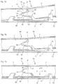
- Fig. 8 shows a second embodiment of the invention.
- the board 1 in Fig. 8 can be used for parquet flooring.
- the board 1 consists of an upper wear layer 32a, a core 30 and a rear balance layer 34a.
- the projecting portion P outside the joint plane F is to a still greater extent made of different combinations of materials.
- the locking groove 14 is reinforced by the use of a separate component 70 of, for instance, wood fibre, which in a suitable manner is connected with the joint edge, for instance by gluing.
- This variant can be used, for instance, on the short side 5b of the board 1.
- a large part of the fixing shoulder 60 is positioned outside the joint plane F.
- Fig. 9 shows a third embodiment of the invention.
- the board 1 in Fig. 9 is usable to provide a strong attachment of the aluminium strip 6.
- a separate part 72 is arranged on the joint edge supporting the locking element 8.
- the part 72 can be made of, for instance, wood fibre.
- the entire fixing shoulder 60 and the entire strip 6 are located outside the joint plane F. Only a small part of the separate strip 6 is used for resilience. From the viewpoint of material, the portion P located outside the joint plane F has three different areas containing the combinations of materials "wood fibre only” (PI), "wood fibre/balance layer/aluminium” (P2) and “aluminium only” (P3).
- PI wood fibre only
- P2 wood fibre/balance layer/aluminium
- P3 aluminium only
- This embodiment with the fixing shoulder 6 positioned entirely outside the joint plane F can also be accomplished merely by working the body of the board, i.e. without the separate part 72.
- the embodiment in Fig. 9 can be suitable for the long side.
- the locking element 8 has a large guiding part, and the projecting portion P outside the joint plane F has a reduced bending down capability.
- the tongues 64 are higher than the lip 62. This results in a strong attachment of the strip 6 in the front edge of the fixing shoulder 60, which is advantageous when bending down the strip 6. This can be achieved without any extra cost of material since the tongues 64 are punched from the existing material.
- the lip 62 can be made lower, which is advantageous in respect of on the one hand consumption of material and, on the other hand, the weakening effect of the mounting groove 54 on the joint edge.
- the locking element 8 in Fig. 8 is lower, which facilitates the snapping in on the short sides.
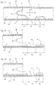
- Figs 10-12 show three different embodiments, in which the projecting portion can be made in one piece with the board body or consists of separate materials which are glued to the edge of the board and are machined from above. Separate materials are particularly suitable on the short side where strength and resilience requirements are high. Such an embodiment means that the composition of materials on the long side and the short side can be different.
- the edge portion is applied to the body before the body is provided with all outer layers, such as top layer and rear balance layer. Especially, such layers can then be applied on top of the fixed, separate edge portion, whereupon the latter can be subjected to working in respect of form with a view to forming part of the joining system, such as the projecting portion with locking element and/or the tongue with locking groove.
- the board body is composed of a top laminate 32, a wood fibre core 30 and a rear laminate 34.
- the locking element 8 is formed by the projecting portion P being worked from above in such manner that, seen from the joint plane F outwards, it has an inner part P1 consisting of wood fibre 30 and laminate 34, a central part P2 consisting of laminate 34 only, and an outer part P3 consisting of wood fibre and laminate 34.
- Figs 10 and 11 differ from each other owing to the fact that in Fig. 10 the boundary between the wood fibre core 30 and the rear laminate 34 is on a vertical level with the lower edge of the active locking surface 10. Thus, in Fig. 10 no significant working of the rear laminate 34 has taken place in the central part P2. On the other hand, in Fig. 11 also the rear laminate 34 has been worked in the central part P2, which gives the advantage that the active locking surface 10 of the locking element 8 is wholly or partly made of a harder material.
- the embodiment in Fig. 12 differs from the embodiments in Figs 10 and 11 by an additional intermediate layer 33 being arranged between the wood fibre core 30 and the rear laminate 34.
- the intermediate layer 33 should be relatively hard and strong to reinforce the active locking surface 10 as shown in Fig. 12 .
- the immediate layer 33 can be made of a separate material which is glued to the inner core.
- the immediate layer 33 may constitute a part of, for instance, a particle board core, where chip material and binder have been specially adapted to the mechanical joining system.
- the core and the intermediate layer 33 can thus both be made of chip material, but with different properties.
- the layers can be optimised for the different functions of the locking system.
- the aspects of the invention including a separate strip can preferably be implemented in combination with the use of an equalising groove of the type described in WO 94/26999 .
- Adjacent joint edges are equalised in the thickness direction by working of the underside, so that the upper sides of the floorboards are flush when the boards are joined.
- Reference letter E in Fig. 1a indicates that the body of the boards after such working has the same thickness in adjacent joint edges.
- the strip 6 is received in the groove and will thus be partly flush-mounted in the underside of the floor. A corresponding arrangement can thus be accomplished also in combination with the invention as shown in the drawings.
Abstract
Description
- The invention generally relates to a locking system for providing mechanical joining of floorboards. More specifically, the invention concerns an improvement of a locking system of the type described and shown in
WO 94/26999 - The invention is particularly suited for mechanical joining of thin floating floorboards, such as laminate and parquet flooring, and therefore the following description of prior art and the objects and features of the invention will be directed to this field of application, in particular rectangular floorboards that are joined on long sides as well as short sides. The features distinguishing the invention concern in the first place parts of the locking system which are related to horizontal locking transversely of the joint edges of the boards. In practice, floorboards will be manufactured according to the inventive principles of also having locking means for mutual vertical locking of the boards.
-
WO 94/26999 SE 9604484-7 SE 9604483-9 - With a view to facilitating the understanding and description of the present invention as well as the understanding of the problems behind the invention, now follows with reference to
Figs 1-3 a brief description of floorboards according toWO 94/26999 - A floorboard 1 of known design is shown from below and from above in
Figs 3a and 3b , respectively. The board is rectangular and has atop side 2, anunderside 3, two oppositelong sides 4a, 4b which form joint edges, and two opposite short sides 5a, 5b which form joint edges. - Both the
long sides 4a, 4b and the short sides 5a, 5b can be joined mechanically without any glue in the direction D2 inFig. 1c . To this end, the board 1 has aplanar strip 6 which is mounted at the factory and which extends horizontally from one long side 4a, the strip extending along the entire long side 4a and being made of a flexible, resilient aluminium sheet. Thestrip 6 can be mechanically fixed according to the illustrated embodiment, or fixed by means of glue or in some other fashion. Other strip materials can be used, such as sheet of some other metal, and aluminium or plastic sections. Alternatively, thestrip 6 can be integrally formed with the board 1, for instance by some suitable working of the body of the board 1. The strip, however, is always integrated with the board 1, i.e. it is not mounted on the board 1 in connection with laying. The width of thestrip 6 can be about 30 mm and its thickness about 0.5 mm. A similar, although shorter strip 6' is arranged also along one short side 5a of the board 1. The edge side of the strip 4 facing away from the joint edge 4a is formed with alocking element 8 extending along theentire strip 6. Thelocking element 8 has anactive locking surface 10 facing the joint edge 4a and having a height of e.g. 0.5 mm. In connection with laying, thelocking element 8 cooperates with alocking groove 14, which is formed in theunderside 3 of the oppositelong side 4b of an adjacent board 1'. The short side strip 6' is provided with a corresponding locking element 8', and the opposite short side 5b has a corresponding locking groove 14'. - For mechanical joining of both long sides and short sides also in the vertical direction (direction D1 in
Fig. 1c ), the board 1 is further along its one long side 4a and its one short side 5a formed with a laterally open recess 16. The recess 16 is defined downwards by theassociated strip 6, 6'. At theopposite edges 4b and 5b there is an upper recess 18 defining a locking tongue 20 (seeFig. 2a ) cooperating with the recess 16 to form a tongue-and-groove joint. -
Figs 1a-1c show how two such boards 1, 1' can be joined by downwards angling.Figs 2a-2c show how the boards 1, 1' can instead be joined by snap action. Thelong sides 4a, 4b can be joined by both methods whereas the short sides 5a, 5b - after laying of the first row - are normally joined after joining of the long sides and merely by snap action. When a new board 1' and a previously laid board 1 are to be joined along their long sides according toFigs 1a-1c , thelong side 4b of the new board 1' is pressed against the long side 4a of the previously laid board 1 according toFig. 1a , so that thelocking tongue 20 is inserted into the recess 16. The board 1' is then angled downwards to thesubfloor 12 according toFig. 1b . Now thelocking tongue 20 completely enters the recess 16 while at the same time thelocking element 8 of thestrip 6 enters thelocking groove 14. During this downwards angling, the upper part of thelocking element 8 can be active and accomplish a guiding of the new board 1' towards the previously laid board 1. In the joined state according toFig. 1c , the boards 1, 1' are locked in both D1 direction and D2 direction, but may be displaced relative to each other in the longitudinal direction of the joint. -
Figs 2a-2c illustrate how also the short sides 5a and 5b of the boards 1, 1' can be mechanically joined in both D1 and D2 direction by the new board 1' being moved essentially horizontally towards the previously laid board 1. This can be carried out after thelong side 4b of the new board 1' has been joined as described above. In the first step inFig. 2a , bevelled surfaces adjacent to the recess 16 and thelocking tongue 20 cooperate so that the strip 6' is forced downwards as a direct consequence of the joining of the short sides 5a, 5b. During the final joining, the strip 6' snaps upwards as the locking element 8' enters the locking groove 14'. By repeating the operations shown inFigs 1 and 2 , the entire floor can be laid without glue and along all joint edges. Thus, prior-art floorboards of the above-mentioned type are joined mechanically by, as a rule, first being angled downwards on the long side, and when the long side is locked, the short sides are snapped together by horizontal displacement along the long side. The boards 1, 1' can be taken up again in reverse order, without the joint being damaged, and be laid once more. - For optimal function, it should be possible for the boards, after being joined, along their long sides to take a position where there is a possibility of a small play between the
locking surface 10 and thelocking groove 14. For a more detailed description of this play, reference is made toWO 94/26999 - In addition to the disclosure of the above-mentioned patent specifications, Norske Skog Flooring AS (licensee of Välinge Aluminium AB) introduced a laminate flooring with a mechanical joining system according to
WO 94/29699 in January 1996 mm aluminium strip 6 which is mechanically fixed to the tongue side and theactive locking surface 10 of thelocking element 8 has an inclination of about 70°-80° to the plane of the board. The joint edges are impregnated with wax and the underside is provided with underlay board which is mounted at the factory. The vertical joint is designed as a modified tongue-and-groove joint. Thestrips 6, 6' on long side and short side are largely identical, but slightly bent upwards to different degrees on long side and short side. The inclination of the active locking surface varies between long side and short side. The distance of thelocking groove 14 from the joint edge, however, is somewhat smaller on the short side than on the long side. The boards are made with a nominal play on the long side which is about 0.05-0.10 mm. This enables displacement of the long sides and bridges width tolerances of the boards. Boards of this brand have been manufactured and sold with zero play on the short sides, which is possible since the short sides need not be displaced in connection with the locking which is effected by snap action. Boards of this brand have also been made with more bevelled portions on the short side to facilitate snapping in according toFigs 2a-c above. It is thus known that the mechanical locking system can be designed in various ways and that long side and short side can be of different design. -
WO 97/47834 (Unilin - Although the flooring according to
WO 94/26999 - Mechanical joints are very suitable for joining not only laminate floorings, but also wood floorings and composite floorings. Such floorboards may consist of a large number of different materials in the surface, the core and the rear side, and as described above these materials can also be included in the strip of the joining system, the locking element on the strip, fixing surfaces, vertical joints etc. This solution involving an integrated strip, however, leads to costs in the form of waste when the mechanical joint is being made. Alternatively, special materials, such as the
aluminium strip 6 above, can be glued or mechanically fixed to the floorboard to be included as components in the joining system. Different joint designs affect the costs to a considerable extent. - A strip made of the same material as the body of the board and formed by working of the body of the board can in some applications be less expensive than an aluminium strip, especially for floorboards in lower price ranges. Aluminium, however, is more advantageous in respect of flexibility, resilience and displaceability as well as accuracy in the positioning of the locking element. Aluminium also affords the possibility of making a stronger locking element. If the same strength is to be achieved with a locking element of wood fibre, it must be wide with a large shearing surface, which results in a large amount of waste material in manufacture, or it must be reinforced with a binder. Depending on the size of the boards, working of, for instance, 10 mm of a joint edge may result in six times higher cost of waste per m2 of floor surface along the long sides compared with the short sides.
- In addition to the above problems relating to undesirable waste of material, the present invention is based on the insight that the long sides and short sides can be optimised with regard to the specific locking functions that should be present in these joint edges.
- As described above, locking of the long side is, as a rule, carried out by downwards angling. Also a small degree of bending down of the strip during locking can take place, as will be described in more detail below. Thanks to this downwards bending together with an inclination of the locking element, the boards can be angled down and up again with very tight joint edges. The locking element along the long sides should also have a high guiding capability so that the long side of a new board in connection with downwards angling is pushed towards the joint edge of the previously laid board. The locking element should have a large guiding part. For optimal function, the boards should along their long sides, after being joined, be able to take a mutual position transversely of the joint edges where there is a small play between locking element and locking groove.
- On the other hand, locking of the short side is carried out by the long side being displaced so that the strip of the short side can be bent down and snap into the locking groove. Thus the short side must have means which accomplish downwards bending of the strip in connection with lateral displacement. The strength requirement is also higher on the short side. Guiding and displaceability are less important.
- Summing up, there is a great need for providing a mechanical joint of the above type at a low cost and with optimal locking functions at each joint edge. It is not possible to achieve a low cost with prior-art solutions without also lowering the requirements as to strength and/or laying function. An object of the invention is to provide solutions which aim at lowering the cost with maintained strength and function. According to the invention, these and other objects are achieved by the floorboards having the features as defined in independent claim 1. Preferred embodiments are stated in the respective dependent claims.
- According to the invention (claim 1), a locking system for mechanical joining of floorboards is thus provided, where immediately juxtaposed upper parts of two adjacent joint edges of two joined floorboards together define a joint plane perpendicular to the principal plane of the floor boards. To obtain a joining of the two joint edges perpendicular to the joint plane, the locking system comprises in a manner known per se a locking groove which is formed in the underside of and extends in parallel with the first joint edge at a distance from the joint plane, and a portion projecting from the lower part of the second joint edge and below the first joint edge and integrated with a body of the board, said projecting portion supporting at a distance from the joint plane a locking element cooperating with the locking groove and thus positioned entirely outside the joint plane seen from the side of the second joint edge, said projecting portion having a different composition of materials compared with the body of the board. The inventive locking system is characterised in that the projecting portion presents at least two horizontally juxtaposed parts, which are composed of different material compositions, and in that said at least two parts are located at different distances from the joint plane.
- According to the invention, said at least two parts of the projecting portion are located at different distances from the joint plane. In particular, they may comprise an inner part closest to the joint plane and an outer part at a distance from the joint plane. The inner part and the outer part are preferably, but not necessarily, of equal length in the joint direction. A material other than that included in the body is thus included in the joining system, and in particular the outer part can be at least partially formed of a separate strip which is made of a material other than that of the body of the board and which is integrally connected with the board by being factory-mounted. The inner part can be formed at least partially of a worked part of the body of the board and partially of part of said separate strip. The separate strip can be attached to such a worked part of the board body. The strip can be located entirely outside said joint plane, but can also intersect the joint plane and extend under the joint edge to be attached to the body also inside the joint plane.
- This invention thus provides a kind of combination strip in terms of material, for example a projecting portion comprising an inner part with the material combination wood fibre/rear laminate/aluminium, and an outer part of aluminium sheet.
- It is also possible to make the projecting part from three parts which are different in terms of material: an inner part closest to the joint plane, a central part and an outer part furthest away from the joint plane. The inner part and the outer part can possibly be equal in terms of material.
- The portion projecting outside the joint plane need not necessarily be continuous or unbroken along the joint edge. A conceivable variant is that the projecting portion has a plurality of separate sections distributed along the joint edge. As an example, this can be accomplished by means of a separate strip with a continuous inner part and a toothed outer part, said strip being attachable to a part of the board body, said part being worked outside the joint plane.
- In an alternative embodiment of the invention, said at least two parts, which differ in respect of at least one of the parameters material composition and material properties, are instead juxtaposed seen in the direction parallel with the joint edges. For example, there may be a plurality of strip types on one and the same side, where each strip type is optimised for a special function, such as strength and guiding in connection with laying. As an example, the strips can be made of different aluminium alloys and/or of aluminium having different states (for instance, as a result of different types of heat treatment).
- According to a an embodiment the projecting portion is instead formed in one piece with the body of the board and thus has the same material composition as the body of the board. This embodiment is characterised in that the projecting portion, as a direct consequence of machining of its upper side, presents at least two horizontally juxtaposed parts, which differ from each other in respect of at least one of the parameters material composition and material properties.
- The inventive principle of dividing the projecting portion into several parts which differ from each other in terms of material thus is applicable also to the prior-art "wood fibre strip".
- In the same manner as described above for the invention, these two parts can be located at different distances from the joint plane, and especially there may be three or more parts with different material composition and/or material properties. Optionally, two such parts can be equal in respect of said parameters, but they may differ from a third.
- In one embodiment, said two parts may comprise an inner part closest to the joint plane and an outer part at a distance from the joint plane. There may be further parts outside the outer part. Specifically, an outer part can be formed of fewer materials than an inner part. For instance, the inner part may consist of wood fibre and rear laminate, whereas the outer part, by machining from above, consists of rear laminate only. In one embodiment, the projecting portion may comprise - seen from the joint plane outwards - an inner part, an outer part and, outside the outer part, a locking element supported by the outer part. The locking element may differ from both inner and outer part in respect of said material parameters.
- The projecting portion may consist of three laminated layers, and therefore it is possible, by working from above, to provide a locking system which, counted from the top, has a relatively soft upper guiding part which need not have any particular strength, a harder central part which forms a strong active locking surface and absorbs shear forces in the locking element, and a lower part which is connected with the rest of the projecting portion and which can be thin, strong and resilient.
- Laminated embodiments can be suitable in such floorboards where the body of the board consists of, for instance, plywood or particle board with several layers. Corresponding layers can be found in the walls of the locking groove. For plywood, the material properties can be varied by changing the direction of fibres in the layers. For particle board, the material properties can be varied by using different chip dimensions and/or a binder in the different layers. The board body can generally consist of layers of different plastic materials.
- In the definition of the invention, the term "projecting portion" relates to the part or parts of the board projecting outside the joint plane and having a function in the locking system in respect of supporting of locking element, strength, flexibility etc.
- An underlay of underlay board, foam, felt or the like can, for instance, be mounted even in the manufacture of the boards on the underside thereof. The underlay can cover the underside up to the locking element, so that the joint between the underlays will be offset relative to the joint plane F. Although such an underlay is positioned outside the joint plane, it should thus not be considered to be included in the definition of the projecting portion in the appended claims.
- In the aspect of the invention which relates to embodiments with a projecting portion of the same material as the body of the board, any thin material layers which remain after working from above should in the same manner not be considered to be included in the "projecting portion" in the cases where such layers do not contribute to the locking function in respect of strength, flexibility, etc. The same discussion applies to thin glue layers, binders, chemicals, etc. which are applied, for instance, to improve moisture proofing and strength.
- The projecting portion of a given joint edge, for instance a long side, has at least two parts with different material compositions. For optimisation of a floorboard, such a difference in materials, however, may be considered to exist between the long sides and short sides of the board instead of within one and the same joint edge.
- According to an embodiment, a rectangular floorboard is thus provided, comprising a body and first and second locking means integrated with the body and adapted to provide a mechanical joining of adjacent joint edges of such floorboards along long sides and short sides, respectively, of the boards in a direction perpendicular to the respective joint edges and in parallel with the principal plane of the floorboards. According to this embodiment, the floorboard is characterised in that said first and second locking means differ in respect of at least one of the parameters material composition and material properties. Preferably, said first and second locking means each comprise on the one hand a portion which projects from a joint edge and which at a distance from the joint edge supports a locking element and, on the other hand, a locking groove, which is formed in the underside of the body at an opposite joint edge for engaging such a locking element of an adjacent board. At least one of said locking means on the long side and the short side may comprise a separate element which is integrally fixed to the body of the board at the factory and is made of a material other than that included in the body of the board. The other locking means may comprise an element which is formed in one piece with the body of the board.
- According to this embodiment, there are several possibilities of combination. For example, it is possible to select an aluminium strip for the long side and a machined wood fibre strip for the short side or vice versa. Another example is that for the short side or the long side a "combination strip" is selected, and for the other side a "pure" aluminium strip or a "pure" worked wood fibre strip is selected.
- The above problem of undesirable costs of material is solved according to the invention by the projecting portion being made of different materials and thus specially adaptable to the selected materials in the floorboard and the function and strength requirements that apply to the specific floorboard and that are specific for long side and short side. This advantage of the invention will be evident from the following description.
- Since different requirements are placed on the long side and the short side and also the cost of waste differs, improvements can also be achieved by the long side and the short side being made of different materials or combinations of materials. In some applications, the long side can have, for instance, an aluminium strip with high guiding capability and low friction whereas the short side can have a wood fibre strip. In other applications, the opposite is advantageous.
- In some applications, there may also be a need for different types of strip on the same side. The side may consist of, for instance, a plurality of different strips which are made of different aluminium alloys, have different thicknesses etc. and in which certain parts are intended to achieve high strength and others are intended to be used for guiding.
- Different aspects of the invention will now be described in more detail by way of examples with reference to the accompanying drawings. The parts of the inventive board which are equivalent to those of the prior-art board in
Figs 1-3 are provided with the same reference numerals. -
-
Figs 1a-c illustrate in three steps a downwards angling method for mechanical joining of long sides of floorboards according toWO 94/26999 -
Figs 2a-c illustrate in three steps a snap-in method for mechanical joining of short sides of floorboards according toWO 94/26999 -
Figs 3 and 3b show a floorboard according toWO 94/26999 -
Fig. 4 shows a floorboard with a locking system according to an embodiment of the invention. -
Fig. 5 is a top plan view of a floorboard according toFig. 4 . -
Fig. 6a shows on a larger scale a broken-away corner portion C1 of the board inFig. 5, and Figs 6b and 6c are vertical sections of the joint edges along the long side 4a and the short side 5a of the board inFig. 5 , from which it is particularly evident that the long side and the short side are different. -
Figs 7a-c show a downwards angling method for mechanical joining of long sides of the floorboard according toFigs 4-6 . -
Fig. 8 shows two joined floorboards provided with a locking system according to a second embodiment of the invention. -
Fig. 9 shows two joined floorboards provided with a locking system according to a third embodiment of the invention. -
Figs 10-12 illustrate three different embodiments of floorboards. - A first preferred embodiment of a floorboard 1 provided with a locking system according to the invention will now be described with reference to
Figs 4-7 . The shown example also illustrates the aspect of the invention which concerns differently designed locking systems for long side and short side. -
Fig. 4 is a cross-sectional view of a long side 4a of the board 1. The body of the board 1 consists of acore 30 of, for instance, wood fibre which supports asurface laminate 32 on its front side and abalance layer 34 on its rear side. The board body 30-34 is rectangular withlong sides 4a, 4b and short sides 5a, 5b. Aseparate strip 6 with a formedlocking element 8 is mounted at the factory on the body 30-34, so that thestrip 6 constitutes an integrated part of the completed floorboard 1. In the shown example, thestrip 6 is made of resilient aluminium sheet. As an illustrative, non-limiting example, the aluminium sheet can have a thickness in the order of 0.6 mm and the floorboard a thickness in the order of 7 mm. For further description of dimensions, possible materials, etc. for thestrip 6, reference is made to the above description of the prior-art board. - The
strip 6 is formed with alocking element 8, whose active lockingsurface 10 cooperates with a lockinggroove 14 in an oppositejoint edge 4b of an adjacent board 1' for horizontal locking together of the boards 1, 1' transversely of the joint edge (D2). With a view to forming a vertical lock in the D1 direction, the joint edge 4a has a laterallyopen groove 36 and the oppositejoint edge 4b has a laterally projecting tongue 38 (corresponding to the locking tongue 20), which in the joined state is received in the groove 36 (Fig. 7c ). The free surface of theupper part 40 of thegroove 36 has a verticalupper portion 41, a bevelledportion 42 and anupper abutment surface 43 for thetongue 38. The free surface of thelower part 44 of thegroove 36 has alower abutment surface 45 for thetongue 38, a bevelled portion 46 and a lower vertical portion 47. The oppositejoint edge 4b (seeFig. 7a ) has an uppervertical portion 48, and thetongue 38 has anupper abutment surface 49, anupper bevelled portion 50, a lower bevelled portion 51 and a lower abutment surface 52. - In the joined state (
Fig. 7c ), the two juxtaposed verticalupper portions Fig. 4 , thelower part 44 of thegroove 36 is extended a distance outside the joint plane F. The joint edge 4a is in its underside formed with a continuous mountinggroove 54 having a vertical lower grippingedge 56 and an inclined grippingedge 58. The gripping edges formed of thesurfaces shoulder 60 for mechanical fixing of thestrip 6. The fixing is carried out according to the same principle as in the prior-art board and can be carried out by means of the methods that are described in the above-mentioned documents. Acontinuous lip 62 of thestrip 6 thus is bent round thegripping edges groove 54, while a plurality of punchedtongues 64 are bent round the surfaces 46, 47 of the projectingportion 44. Thetongues 64 and the associated punchedholes 65 are shown in the broken-out view inFig. 6a . - There is a significant difference between the inventive floorboard shown in
Figs 4-7 and the prior-art board according toFigs 1-3 . The area P inFig. 4 designates the portion of the board 1 which is positioned outside the joint plane 1. According to the invention, the portion P has two horizontally juxtaposed parts P1 and P2, which differ in respect of their material composition. More specifically, the inner part P1 is, closest to the joint plane F, formed partially of thestrip 6 and partially of the workedpart 44 of the body. In this embodiment, the inner part P1 thus comprises the material combination aluminium + wood fibre core + rear laminate whereas the outer part P2 is a made of aluminium only. In the prior-art board 1 inFigs 1a-c , the corresponding portion outside the joint plane is made of aluminium only. - As described above, this feature of the invention means that the cost of material can be reduced. Thanks to the fact that the fixing
shoulder 60 is displaced towards the lockingelement 8 to such an extent that it is positioned at least partially outside the joint plane F, a considerable saving can be achieved in respect of the consumption of aluminium sheet. A saving in the order of 25% is possible. This embodiment is particularly advantageous in cheaper floorboards where waste of wood fibre as a result of machining of the body is preferred to a high consumption of aluminium sheet. The waste of material, however, is limited thanks to the fact that the projecting portion can also be used as abutment surface for the tongue, which can then be made correspondingly narrower perpendicular to the joint plane with the ensuing reduced waste of material on the tongue side. - This constructional change to achieve saving in material does not have a detrimental effect on the possibility of resilient vertical motion that must exist in the projecting portion P. The strength of the
locking element 8 is not affected either. The outer part P2 of aluminium is still fully resilient in the vertical direction, and the short sides 5a, 5b can be snapped together according to the same principle as inFigs 2a-c . The lockingelement 8 is still made of aluminium and its strength is not reduced. However, it may be noted that the degree of resilience can be affected since it is essentially only the outer part P2 that is resilient in the snap action. This can be an advantage in some cases if one wants to restrict the bending-down properties and increase the strength of the lock. - The angling together of the
long sides 4a, 4b can also be carried out according to the same principle as inFigs 1a-c . In general - not only in this embodiment - a small degree of downwards bending of thestrip 6 may occur, as shown in the laying sequence inFigs 7a-c . This downwards bending of thestrip 6 together with an inclination of thelocking element 8 makes it possible for the boards 1, 1' to be angled down and up again with very tight joint edges at theupper surfaces element 8 should preferably have a high guiding capability so that the boards, in connection with downwards angling, are pushed towards the joint edge. The lockingelement 8 should have a large guiding part. For optimal function, the boards should, after being joined and along theirlong sides 4a, 4b, be able to take a position where there is a small play between locking element and locking groove, which need not be greater than about 0.02-0.05 mm. This play permits displacement and bridges width tolerances. The friction in the joint should be low. - In the joined state according to
Fig. 7c , the boards 1, 1' are locked relative to each other in the vertical direction D1. An upwards movement of the board 1' is counteracted by engagement between thesurfaces surfaces 45 and 52 and, on the other hand, by the board 1 resting on the upper side of thestrip 6. -
Fig. 8 shows a second embodiment of the invention. The board 1 inFig. 8 can be used for parquet flooring. The board 1 consists of an upper wear layer 32a, acore 30 and a rear balance layer 34a. In this embodiment, the projecting portion P outside the joint plane F is to a still greater extent made of different combinations of materials. The lockinggroove 14 is reinforced by the use of a separate component 70 of, for instance, wood fibre, which in a suitable manner is connected with the joint edge, for instance by gluing. This variant can be used, for instance, on the short side 5b of the board 1. Moreover, a large part of the fixingshoulder 60 is positioned outside the joint plane F. -
Fig. 9 shows a third embodiment of the invention. The board 1 inFig. 9 is usable to provide a strong attachment of thealuminium strip 6. In this embodiment, aseparate part 72 is arranged on the joint edge supporting thelocking element 8. Thepart 72 can be made of, for instance, wood fibre. The entire fixingshoulder 60 and theentire strip 6 are located outside the joint plane F. Only a small part of theseparate strip 6 is used for resilience. From the viewpoint of material, the portion P located outside the joint plane F has three different areas containing the combinations of materials "wood fibre only" (PI), "wood fibre/balance layer/aluminium" (P2) and "aluminium only" (P3). This embodiment with the fixingshoulder 6 positioned entirely outside the joint plane F can also be accomplished merely by working the body of the board, i.e. without theseparate part 72. The embodiment inFig. 9 can be suitable for the long side. The lockingelement 8 has a large guiding part, and the projecting portion P outside the joint plane F has a reduced bending down capability. - When comparing the embodiments in
Figs 8 and 9 , it may be noted that inFig. 9 thetongues 64 are higher than thelip 62. This results in a strong attachment of thestrip 6 in the front edge of the fixingshoulder 60, which is advantageous when bending down thestrip 6. This can be achieved without any extra cost of material since thetongues 64 are punched from the existing material. On the other hand, thelip 62 can be made lower, which is advantageous in respect of on the one hand consumption of material and, on the other hand, the weakening effect of the mountinggroove 54 on the joint edge. It should further be noted that the lockingelement 8 inFig. 8 is lower, which facilitates the snapping in on the short sides. -
Figs 10-12 show three different embodiments, in which the projecting portion can be made in one piece with the board body or consists of separate materials which are glued to the edge of the board and are machined from above. Separate materials are particularly suitable on the short side where strength and resilience requirements are high. Such an embodiment means that the composition of materials on the long side and the short side can be different. - The above technique of providing the edge of the body, on the long side and/or short side, with separate materials that are fixed to the body to achieve special functions, such as strength, moisture proofing, flexibility etc, can be used also without utilising the principles of the invention. In other words, it is possible also in other joining systems, especially mechanical joining systems, to provide the body with separate materials in this way. In particular, this material can be applied as an edge portion, which in some suitable fashion is attached to the edge of the body and which can extend over the height of the entire board or parts thereof.
- In a preferred embodiment, the edge portion is applied to the body before the body is provided with all outer layers, such as top layer and rear balance layer. Especially, such layers can then be applied on top of the fixed, separate edge portion, whereupon the latter can be subjected to working in respect of form with a view to forming part of the joining system, such as the projecting portion with locking element and/or the tongue with locking groove.
- In
Figs 10 and 11 , the board body is composed of atop laminate 32, awood fibre core 30 and arear laminate 34. The lockingelement 8 is formed by the projecting portion P being worked from above in such manner that, seen from the joint plane F outwards, it has an inner part P1 consisting ofwood fibre 30 andlaminate 34, a central part P2 consisting oflaminate 34 only, and an outer part P3 consisting of wood fibre andlaminate 34. - The embodiments in
Figs 10 and 11 differ from each other owing to the fact that inFig. 10 the boundary between thewood fibre core 30 and therear laminate 34 is on a vertical level with the lower edge of theactive locking surface 10. Thus, inFig. 10 no significant working of therear laminate 34 has taken place in the central part P2. On the other hand, inFig. 11 also therear laminate 34 has been worked in the central part P2, which gives the advantage that theactive locking surface 10 of thelocking element 8 is wholly or partly made of a harder material. - The embodiment in
Fig. 12 differs from the embodiments inFigs 10 and 11 by an additionalintermediate layer 33 being arranged between thewood fibre core 30 and therear laminate 34. Theintermediate layer 33 should be relatively hard and strong to reinforce theactive locking surface 10 as shown inFig. 12 . For example, theimmediate layer 33 can be made of a separate material which is glued to the inner core. Alternatively, theimmediate layer 33 may constitute a part of, for instance, a particle board core, where chip material and binder have been specially adapted to the mechanical joining system. In this alternative, the core and theintermediate layer 33 can thus both be made of chip material, but with different properties. The layers can be optimised for the different functions of the locking system. - Moreover, the aspects of the invention including a separate strip can preferably be implemented in combination with the use of an equalising groove of the type described in
WO 94/26999 Fig. 1a indicates that the body of the boards after such working has the same thickness in adjacent joint edges. Thestrip 6 is received in the groove and will thus be partly flush-mounted in the underside of the floor. A corresponding arrangement can thus be accomplished also in combination with the invention as shown in the drawings.
Claims (15)
- Floorboards provided with a locking system for mechanical joining of said floorboards (1, 1'), in which immediately juxtaposed upper parts (41, 48) of two adjacent joint edges (4a, 4b; 5a, 5b) of two of said joined floorboards (1, 1') together define a joint plane (F) perpendicular to the principal plane of the floorboards, said locking system for providing a joining of the two joint edges (4a, 4b; 5a, 5b) perpendicular to the joint plane (F) comprising a locking groove (14) which is formed in the underside (3) of and extends in parallel with the first joint edge (4b, 5b) at a distance from the joint plane (F) and a portion (P) projecting from the lower part of the second joint edge (4a, 5a) and below the first joint edge (4b, 5b) and integrated with a body (30, 32, 34) of the board (1), said projecting portion (P) supporting at a distance from the joint plane (F) a locking element (8) cooperating with the locking groove (14), said projecting portion (P) thus being located entirely outside the joint plane (F) seen from the side of the second joint edge, and said projecting portion (P) having a material composition other than that of the body of the board, characterised in that the projecting portion (P) presents at least two horizontally juxtaposed parts (P1, P2), which are composed of different material compositions, and in that said at least two parts (P1, P2) are located at different distances from the joint plane (F).
- The floorboards as claimed in claim 1, wherein said parts (P1, P2) comprise an inner part (P1) closest to the joint plane (F) and an outer part (P2) at a distance from the joint plane (F).
- The floorboards as claimed in claim 2, wherein the outer part (P2) is at least partially formed of a separate strip (6, 6'), which is made of a material different from that of the body of the board and which is integrally connected with the board by being factory-mounted.
- The floorboards as claimed in claim 2 or 3, wherein the inner part (P1) is formed at least partially of a worked part (44) of the body of the board.
- The floorboards as claimed in claims 3 and 4, wherein the inner part (P1) is formed at least on the one hand of said worked part (44) of the body of the board and, on the other hand, of a part of said separate strip (6, 6').
- The floorboards as claimed in claim 4, wherein the inner part (P1) is formed merely of a worked part of the body of the board.
- The floorboards as claimed in any one of claims 4-6, wherein said locking system also comprises a vertical locking means, for providing a joining of the two joint edges (4a, 4b; 5a, 5b) also perpendicular (D1) to the principal plane of the boards (1, 1').
- The floorboards as claimed in claim 5, wherein the strip (6, 6') is attached (64) to said worked part (44) of the body of the board.
- The floorboards as claimed in claim 6, wherein the strip (6) intersects the joint plane (F) and extends under said second joint edge (4a, 5a).
- The floorboards as claimed in any one of claims 5-8, wherein the strip (6) is located entirely outside the joint plane (F).
- The floorboards as claimed in any one of claims 3-10, wherein the strip (6) is mechanically attached (60, 62, 64) .
- The floorboards as claimed in any one of claims 2-11, wherein the outer part (P2) is resilient in the direction (D1) transversely of the principal plane of boards.
- The floorboards as claimed in any one of claims 1-12, wherein the portion (P) projecting outside the joint plane (F) is extended continuously along essentially the entire length of said second joint edge (4a, 5a).
- The floorboards as claimed in any one of claims 1-13, wherein the portion (P) projecting outside the joint plane (F) has a plurality of separate sections distributed along said second joint edge (4a, 5a).
- The floorboards as claimed claim 1, wherein said at least two parts are juxtaposed in a direction parallel with the joint edges.
Applications Claiming Priority (5)
| Application Number | Priority Date | Filing Date | Title |
|---|---|---|---|
| SE9801986A SE512313C2 (en) | 1998-06-03 | 1998-06-03 | Locking system and floorboard |
| EP02006617A EP1215352B1 (en) | 1998-06-03 | 1999-05-31 | Rectangular floorboard |
| EP04009352.8A EP1437457B1 (en) | 1998-06-03 | 1999-05-31 | Floorboard |
| PCT/SE1999/000934 WO1999066152A1 (en) | 1998-06-03 | 1999-05-31 | Locking system and flooring board |
| EP99930053A EP1084318B2 (en) | 1998-06-03 | 1999-05-31 | Flooring board |
Related Parent Applications (6)
| Application Number | Title | Priority Date | Filing Date |
|---|---|---|---|
| EP02006617A Division EP1215352B1 (en) | 1998-06-03 | 1999-05-31 | Rectangular floorboard |
| EP99930053.6 Division | 1999-05-31 | ||
| EP99930053A Division EP1084318B2 (en) | 1998-06-03 | 1999-05-31 | Flooring board |
| EP04009352.8A Division EP1437457B1 (en) | 1998-06-03 | 1999-05-31 | Floorboard |
| EP02006617.1 Division | 2002-03-25 | ||
| EP04009352.8 Division | 2004-04-20 |
Publications (3)
| Publication Number | Publication Date |
|---|---|
| EP2275620A2 EP2275620A2 (en) | 2011-01-19 |
| EP2275620A3 EP2275620A3 (en) | 2014-09-10 |
| EP2275620B1 true EP2275620B1 (en) | 2018-08-01 |
Family
ID=20411582
Family Applications (4)
| Application Number | Title | Priority Date | Filing Date |
|---|---|---|---|
| EP04009352.8A Expired - Lifetime EP1437457B1 (en) | 1998-06-03 | 1999-05-31 | Floorboard |
| EP02006617A Revoked EP1215352B1 (en) | 1998-06-03 | 1999-05-31 | Rectangular floorboard |
| EP10180452.4A Expired - Lifetime EP2275620B1 (en) | 1998-06-03 | 1999-05-31 | Floorboards |
| EP99930053A Expired - Lifetime EP1084318B2 (en) | 1998-06-03 | 1999-05-31 | Flooring board |
Family Applications Before (2)
| Application Number | Title | Priority Date | Filing Date |
|---|---|---|---|
| EP04009352.8A Expired - Lifetime EP1437457B1 (en) | 1998-06-03 | 1999-05-31 | Floorboard |
| EP02006617A Revoked EP1215352B1 (en) | 1998-06-03 | 1999-05-31 | Rectangular floorboard |
Family Applications After (1)
| Application Number | Title | Priority Date | Filing Date |
|---|---|---|---|
| EP99930053A Expired - Lifetime EP1084318B2 (en) | 1998-06-03 | 1999-05-31 | Flooring board |
Country Status (19)
| Country | Link |
|---|---|
| US (3) | US6446405B1 (en) |
| EP (4) | EP1437457B1 (en) |
| JP (4) | JP3703717B2 (en) |
| CN (2) | CN1247867C (en) |
| AT (2) | ATE254708T1 (en) |
| AU (2) | AU747344B2 (en) |
| BR (2) | BRPI9917676B1 (en) |
| CA (1) | CA2333941C (en) |
| DE (5) | DE69916666T2 (en) |
| DK (3) | DK1084318T4 (en) |
| ES (3) | ES2219598T3 (en) |
| GR (1) | GR20010300015T1 (en) |
| NO (1) | NO314908B1 (en) |
| NZ (1) | NZ508537A (en) |
| PT (3) | PT1215352E (en) |
| RU (1) | RU2220267C2 (en) |
| SE (1) | SE512313C2 (en) |
| SI (1) | SI1084318T2 (en) |
| WO (1) | WO1999066152A1 (en) |
Families Citing this family (184)
| Publication number | Priority date | Publication date | Assignee | Title |
|---|---|---|---|---|
| SE515210C2 (en) * | 2000-04-10 | 2001-06-25 | Valinge Aluminium Ab | Locking systems for joining floorboards and floorboards provided with such locking systems and floors formed from such floorboards |
| SE509060C2 (en) * | 1996-12-05 | 1998-11-30 | Valinge Aluminium Ab | Method for manufacturing building board such as a floorboard |
| SE9301595L (en) | 1993-05-10 | 1994-10-17 | Tony Pervan | Grout for thin liquid hard floors |
| US7086205B2 (en) | 1993-05-10 | 2006-08-08 | Valinge Aluminium Ab | System for joining building panels |
| SE9500810D0 (en) | 1995-03-07 | 1995-03-07 | Perstorp Flooring Ab | Floor tile |
| US7131242B2 (en) | 1995-03-07 | 2006-11-07 | Pergo (Europe) Ab | Flooring panel or wall panel and use thereof |
| US6588166B2 (en) | 1995-03-07 | 2003-07-08 | Pergo (Europe) Ab | Flooring panel or wall panel and use thereof |
| US6421970B1 (en) | 1995-03-07 | 2002-07-23 | Perstorp Flooring Ab | Flooring panel or wall panel and use thereof |
| US7992358B2 (en) | 1998-02-04 | 2011-08-09 | Pergo AG | Guiding means at a joint |
| SE512313C2 (en) * | 1998-06-03 | 2000-02-28 | Valinge Aluminium Ab | Locking system and floorboard |
| US7386963B2 (en) | 1998-06-03 | 2008-06-17 | Valinge Innovation Ab | Locking system and flooring board |
| SE512290C2 (en) | 1998-06-03 | 2000-02-28 | Valinge Aluminium Ab | Locking system for mechanical joining of floorboards and floorboard provided with the locking system |
| BE1012141A6 (en) * | 1998-07-24 | 2000-05-02 | Unilin Beheer Bv | FLOOR COVERING, FLOOR PANEL THEREFOR AND METHOD for the realization of such floor panel. |
| SE514645C2 (en) | 1998-10-06 | 2001-03-26 | Perstorp Flooring Ab | Floor covering material comprising disc-shaped floor elements intended to be joined by separate joint profiles |
| SE517478C2 (en) | 1999-04-30 | 2002-06-11 | Valinge Aluminium Ab | Locking system for mechanical hoisting of floorboards, floorboard provided with the locking system and method for producing mechanically foldable floorboards |
| US7877956B2 (en) | 1999-07-05 | 2011-02-01 | Pergo AG | Floor element with guiding means |
| AT413227B (en) * | 1999-07-23 | 2005-12-15 | Kaindl M | PANEL OR LUMINOUS COMPONENTS OR ARRANGEMENT WITH SUCH COMPONENTS AND CLAMPS HIEFÜR |
| US6863768B2 (en) | 1999-11-08 | 2005-03-08 | Premark Rwp Holdings Inc. | Water resistant edge of laminate flooring |
| US7763345B2 (en) | 1999-12-14 | 2010-07-27 | Mannington Mills, Inc. | Thermoplastic planks and methods for making the same |
| US6332733B1 (en) | 1999-12-23 | 2001-12-25 | Hamberger Industriewerke Gmbh | Joint |
| AU4743800A (en) * | 1999-12-23 | 2001-07-09 | Hamberger Industriewerke Gmbh | Joint |
| CA2363184A1 (en) * | 1999-12-27 | 2001-07-05 | Kronospan Technical Company Limited | Panel with a shaped plug-in section |
| SE517183C2 (en) | 2000-01-24 | 2002-04-23 | Valinge Aluminium Ab | Locking system for mechanical joining of floorboards, floorboard provided with the locking system and method for making such floorboards |
| SE518184C2 (en) | 2000-03-31 | 2002-09-03 | Perstorp Flooring Ab | Floor covering material comprising disc-shaped floor elements which are joined together by means of interconnecting means |
| FR2807694B1 (en) | 2000-04-14 | 2002-07-05 | Europ De Laquage Et De Faconna | DEVICE FOR ASSEMBLING LONGITUDINAL EDGES OF PANELS, SLATS OR PANELS |
| FR2808822B1 (en) | 2000-05-15 | 2003-01-03 | Europ De Laquage Et De Faconna | DEVICE FOR ASSEMBLING THE LONGITUDINAL EDGES OF PANELS, SLATS OR PANELS, WITH FORCE DISTRIBUTION |
| DE20008708U1 (en) * | 2000-05-16 | 2000-09-14 | Kronospan Tech Co Ltd | Panels with coupling agents |
| BE1013569A3 (en) | 2000-06-20 | 2002-04-02 | Unilin Beheer Bv | Floor covering. |
| ATE272152T1 (en) * | 2000-09-01 | 2004-08-15 | Johannes Schulte | PANEL FOR A PARQUET FLOOR AND METHOD FOR PRODUCING A PANEL FOR A PARQUET FLOOR |
| US20040074190A1 (en) * | 2000-10-08 | 2004-04-22 | Hai Lin | Two-ply flooring having a cross-grain bottom ply |
| WO2002031290A1 (en) * | 2000-10-12 | 2002-04-18 | Josef Hrovath | Tile |
| CA2359419A1 (en) * | 2000-11-20 | 2002-05-20 | Curt Richard Haffner | Decorative laminate panel with water resistant edge |
| US6769218B2 (en) | 2001-01-12 | 2004-08-03 | Valinge Aluminium Ab | Floorboard and locking system therefor |
| US6851241B2 (en) * | 2001-01-12 | 2005-02-08 | Valinge Aluminium Ab | Floorboards and methods for production and installation thereof |
| US6415466B1 (en) * | 2001-03-12 | 2002-07-09 | Elene Laiso | Pocket pillow and sheet for adult/crib elevation sleep aid |
| FR2825734B1 (en) | 2001-06-12 | 2004-07-09 | Europ De Laquage Et De Faconna | DEVICE FOR ASSEMBLING PANELS, SLATS OR PANELS, WITH FORCE DISTRIBUTION |
| US8028486B2 (en) | 2001-07-27 | 2011-10-04 | Valinge Innovation Ab | Floor panel with sealing means |
| SE519791C2 (en) * | 2001-07-27 | 2003-04-08 | Valinge Aluminium Ab | System for forming a joint between two floorboards, floorboards therefore provided with sealing means at the joint edges and ways of manufacturing a core which is processed into floorboards |
| FR2828703A1 (en) | 2001-08-14 | 2003-02-21 | Europ De Laquage Et De Faconna | PROCESS FOR LAYING PANELS, SLATS OR SIDINGS INCLUDING A FORCE DISTRIBUTION EDGE ASSEMBLY DEVICE |
| US8250825B2 (en) | 2001-09-20 | 2012-08-28 | Välinge Innovation AB | Flooring and method for laying and manufacturing the same |
| SE525558C2 (en) * | 2001-09-20 | 2005-03-08 | Vaelinge Innovation Ab | System for forming a floor covering, set of floorboards and method for manufacturing two different types of floorboards |
| US20030093964A1 (en) * | 2001-10-16 | 2003-05-22 | Bushey Richard D. | Floor grid system |
| DE10151614C1 (en) * | 2001-10-23 | 2003-04-24 | Kaindl Wals M | Floor panel has a sound-improving layer provided on its bottom side which is attached by means of an amino plastic material |
| US20030145551A1 (en) * | 2002-02-05 | 2003-08-07 | Grant David R. | Self gapping wood based panels |
| US6772569B2 (en) * | 2002-02-06 | 2004-08-10 | John Landus Bennett | Tongue and groove panel |
| SE525661C2 (en) | 2002-03-20 | 2005-03-29 | Vaelinge Innovation Ab | Floor boards decorative joint portion making system, has surface layer with underlying layer such that adjoining edge with surface has underlying layer parallel to horizontal plane |
| US20040226489A1 (en) * | 2002-03-28 | 2004-11-18 | Greene Joseph Paul | Interlocking modular tubular pallet |
| AU2003217124B2 (en) | 2002-04-03 | 2008-08-14 | Valinge Innovation Ab | Mechanical locking system for floorboards |
| SE525657C2 (en) | 2002-04-08 | 2005-03-29 | Vaelinge Innovation Ab | Flooring boards for floating floors made of at least two different layers of material and semi-finished products for the manufacture of floorboards |
| US8850769B2 (en) | 2002-04-15 | 2014-10-07 | Valinge Innovation Ab | Floorboards for floating floors |
| US7739849B2 (en) | 2002-04-22 | 2010-06-22 | Valinge Innovation Ab | Floorboards, flooring systems and methods for manufacturing and installation thereof |
| US7441384B2 (en) | 2002-08-14 | 2008-10-28 | Columbia Insurance Company | Pre-glued tongue and groove flooring |
| US8375673B2 (en) * | 2002-08-26 | 2013-02-19 | John M. Evjen | Method and apparatus for interconnecting paneling |
| US7617651B2 (en) * | 2002-11-12 | 2009-11-17 | Kronotec Ag | Floor panel |
| DE10262235B4 (en) | 2002-11-12 | 2010-05-12 | Kronotec Ag | Particle board, in particular floor panel or furniture panel, and method for its production |
| DE10252865A1 (en) * | 2002-11-12 | 2004-05-27 | Kronotec Ag | Process for creating a structured decoration in a wood-based panel |
| ATE395481T1 (en) | 2002-11-15 | 2008-05-15 | Flooring Technologies Ltd | DEVICE CONSISTS OF TWO BUILDING PLATES THAT CAN BE CONNECTED TO EACH OTHER AND AN INSERT FOR LOCKING THESE BUILDING PLATES |
| DE10306118A1 (en) | 2003-02-14 | 2004-09-09 | Kronotec Ag | building board |
| US20040206036A1 (en) * | 2003-02-24 | 2004-10-21 | Valinge Aluminium Ab | Floorboard and method for manufacturing thereof |
| RU2329363C2 (en) * | 2003-02-24 | 2008-07-20 | Велинге Инновейшн Аб | Batten and method to produce thereof |
| US7677001B2 (en) | 2003-03-06 | 2010-03-16 | Valinge Innovation Ab | Flooring systems and methods for installation |
| US7845140B2 (en) | 2003-03-06 | 2010-12-07 | Valinge Innovation Ab | Flooring and method for installation and manufacturing thereof |
| US7678425B2 (en) | 2003-03-06 | 2010-03-16 | Flooring Technologies Ltd. | Process for finishing a wooden board and wooden board produced by the process |
| EP2224072B1 (en) * | 2003-03-06 | 2012-05-09 | Välinge Innovation AB | Flooring systems and methods for installation |
| US7185469B2 (en) * | 2003-03-14 | 2007-03-06 | Advantage Architectural Products, Ltd. | Modular raised wall paneling system |
| DE20304761U1 (en) | 2003-03-24 | 2004-04-08 | Kronotec Ag | Device for connecting building boards, in particular floor panels |
| DE10332490B3 (en) * | 2003-07-16 | 2004-08-12 | Johannes Schulte | Parquet flooring panel provided with adjacent end inserts of softwood with cooperating reception grooves and clip tongues their wood grains aligned in opposite directions |
| DE10341172B4 (en) | 2003-09-06 | 2009-07-23 | Kronotec Ag | Method for sealing a building board |
| DE20315676U1 (en) | 2003-10-11 | 2003-12-11 | Kronotec Ag | Panel, especially floor panel |
| US7886497B2 (en) | 2003-12-02 | 2011-02-15 | Valinge Innovation Ab | Floorboard, system and method for forming a flooring, and a flooring formed thereof |
| US7261947B2 (en) * | 2003-12-04 | 2007-08-28 | Awi Licensing Company | Plywood laminate having improved dimensional stability and resistance to warping and delamination |
| US7506481B2 (en) * | 2003-12-17 | 2009-03-24 | Kronotec Ag | Building board for use in subfloors |
| US7516588B2 (en) | 2004-01-13 | 2009-04-14 | Valinge Aluminium Ab | Floor covering and locking systems |
| US20050166516A1 (en) | 2004-01-13 | 2005-08-04 | Valinge Aluminium Ab | Floor covering and locking systems |
| DE102004005047B3 (en) * | 2004-01-30 | 2005-10-20 | Kronotec Ag | Method and device for introducing a strip forming the spring of a plate |
| DE102004011531C5 (en) * | 2004-03-08 | 2014-03-06 | Kronotec Ag | Wood-based panel, in particular floor panel |
| DE102004011931B4 (en) * | 2004-03-11 | 2006-09-14 | Kronotec Ag | Insulation board made of a wood-material-binder fiber mixture |
| BE1016216A5 (en) * | 2004-09-24 | 2006-05-02 | Flooring Ind Ltd | FLOOR PANEL AND FLOOR COVERING COMPOSED OF SUCH FLOOR PANELS. |
| SE527570C2 (en) | 2004-10-05 | 2006-04-11 | Vaelinge Innovation Ab | Device and method for surface treatment of sheet-shaped material and floor board |
| US7841144B2 (en) | 2005-03-30 | 2010-11-30 | Valinge Innovation Ab | Mechanical locking system for panels and method of installing same |
| EP1936068B1 (en) | 2004-10-22 | 2011-11-30 | Välinge Innovation AB | A method of providing floor panels with a mechanical locking system |
| US7454875B2 (en) | 2004-10-22 | 2008-11-25 | Valinge Aluminium Ab | Mechanical locking system for floor panels |
| US7748183B2 (en) * | 2004-11-09 | 2010-07-06 | Composite Foam Material Technology, Llc | System, methods and compositions for attaching paneling to a building surface |
| US8215078B2 (en) | 2005-02-15 | 2012-07-10 | Välinge Innovation Belgium BVBA | Building panel with compressed edges and method of making same |
| ATE440190T1 (en) * | 2005-02-15 | 2009-09-15 | Valinge Innovation Ab | METHOD FOR PRODUCING FLOORING PANELS WITH COMPRESSED EDGES |
| US20060185284A1 (en) * | 2005-02-24 | 2006-08-24 | Alan Tolley | Metal bricks for forming a decorative surface |
| US20130139478A1 (en) | 2005-03-31 | 2013-06-06 | Flooring Industries Limited, Sarl | Methods for packaging floor panels, as well as packed set of floor panels |
| BE1016938A6 (en) * | 2005-03-31 | 2007-10-02 | Flooring Ind Ltd | Floor panel manufacturing method, involves providing panels at lower side with guiding groove and providing two opposite sides with profiled edge regions that comprise coupling parts |
| US8061104B2 (en) | 2005-05-20 | 2011-11-22 | Valinge Innovation Ab | Mechanical locking system for floor panels |
| US20060260252A1 (en) * | 2005-05-23 | 2006-11-23 | Quality Craft Ltd. | Connection for laminate flooring |
| SE529664C2 (en) * | 2005-07-11 | 2007-10-16 | Pergo Europ Ab | A joint profile for a panel |
| DE102005042658B3 (en) | 2005-09-08 | 2007-03-01 | Kronotec Ag | Tongued and grooved board for flooring has at least one side surface and tongue and/or groove with decorative layer applied |
| US7854986B2 (en) | 2005-09-08 | 2010-12-21 | Flooring Technologies Ltd. | Building board and method for production |
| DE102005042657B4 (en) | 2005-09-08 | 2010-12-30 | Kronotec Ag | Building board and method of manufacture |
| DE102005063034B4 (en) | 2005-12-29 | 2007-10-31 | Flooring Technologies Ltd. | Panel, in particular floor panel |
| US20070175144A1 (en) * | 2006-01-11 | 2007-08-02 | Valinge Innovation Ab | V-groove |
| SE530653C2 (en) | 2006-01-12 | 2008-07-29 | Vaelinge Innovation Ab | Moisture-proof floor board and floor with an elastic surface layer including a decorative groove |
| DE102006006124A1 (en) * | 2006-02-10 | 2007-08-23 | Flooring Technologies Ltd. | Device for locking two building panels |
| DE102006007976B4 (en) | 2006-02-21 | 2007-11-08 | Flooring Technologies Ltd. | Process for refining a building board |
| US20070251173A1 (en) * | 2006-05-01 | 2007-11-01 | Stokes Stokes | Flat strip with one or more slight bends with one or more guides and two or more terminal fasteners for interlocking three or more floor planks and a method of creating a floor of hardwood, laminate or artificial floor planks using a flat strip |
| BE1017157A3 (en) | 2006-06-02 | 2008-03-04 | Flooring Ind Ltd | FLOOR COVERING, FLOOR ELEMENT AND METHOD FOR MANUFACTURING FLOOR ELEMENTS. |
| US20070289249A1 (en) * | 2006-06-16 | 2007-12-20 | David Martel | L-shape slotted deck board and hidden fastener system |
| SE533410C2 (en) | 2006-07-11 | 2010-09-14 | Vaelinge Innovation Ab | Floor panels with mechanical locking systems with a flexible and slidable tongue as well as heavy therefore |
| US7861482B2 (en) | 2006-07-14 | 2011-01-04 | Valinge Innovation Ab | Locking system comprising a combination lock for panels |
| US8065851B2 (en) | 2006-08-25 | 2011-11-29 | Huber Engineered Woods Llc | Self-spacing wood composite panels |
| US8323016B2 (en) | 2006-09-15 | 2012-12-04 | Valinge Innovation Belgium Bvba | Device and method for compressing an edge of a building panel and a building panel with compressed edges |
| US11725394B2 (en) | 2006-11-15 | 2023-08-15 | Välinge Innovation AB | Mechanical locking of floor panels with vertical folding |
| US8689512B2 (en) | 2006-11-15 | 2014-04-08 | Valinge Innovation Ab | Mechanical locking of floor panels with vertical folding |
| SE531111C2 (en) * | 2006-12-08 | 2008-12-23 | Vaelinge Innovation Ab | Mechanical locking of floor panels |
| ES2328204B1 (en) * | 2007-07-16 | 2010-05-24 | Perfilstar, S.A. | REMATE DEVICE FOR SURFACE COVERS OF LAMAS. |
| JP4946769B2 (en) * | 2007-10-04 | 2012-06-06 | パナソニック株式会社 | Flooring |
| WO2009061279A1 (en) * | 2007-11-07 | 2009-05-14 | Välinge Innovation AB | Mechanical locking of floor panels with vertical snap folding and an installation method to connect such panels |
| US8353140B2 (en) | 2007-11-07 | 2013-01-15 | Valinge Innovation Ab | Mechanical locking of floor panels with vertical snap folding |
| US7805903B2 (en) * | 2007-12-13 | 2010-10-05 | Liu David C | Locking mechanism for flooring boards |
| US8627862B2 (en) | 2008-01-31 | 2014-01-14 | Valinge Innovation Ab | Mechanical locking of floor panels, methods to install and uninstall panels, a method and an equipment to produce the locking system, a method to connect a displaceable tongue to a panel and a tongue blank |
| CA2623707A1 (en) * | 2008-03-07 | 2009-09-07 | Pierre Trudel | Tongue and groove profile to ease desassembly of floorboards |
| CN102066674B (en) | 2008-05-15 | 2015-06-03 | 瓦林格创新股份有限公司 | Floor panels with a mechanical locking system activated by a magnetic field and a method to install the panels |
| CN201224979Y (en) * | 2008-07-17 | 2009-04-22 | 大连春岛木业集成木有限公司 | Metal lock catch solid wood composite floor |
| US7954292B2 (en) | 2008-09-12 | 2011-06-07 | Progressive Foam Technologies, Inc. | Insulated siding system |
| PT2599934T (en) * | 2009-01-30 | 2018-12-06 | Vaelinge Innovation Ab | Mechanical locking of floor panels |
| CN104372879B (en) * | 2009-02-27 | 2016-12-07 | 阿姆斯特郎世界工业公司 | Linear surface covering system |
| USD656245S1 (en) * | 2009-04-16 | 2012-03-20 | Rene St-Cyr (1996) Inc. | Floor plank |
| BE1018728A3 (en) | 2009-04-22 | 2011-07-05 | Flooring Ind Ltd Sarl | FLOOR PANEL. |
| US11717901B2 (en) | 2009-07-31 | 2023-08-08 | Valinge Innovation Ab | Methods and arrangements relating to edge machining of building panels |
| RU2534578C2 (en) | 2009-07-31 | 2014-11-27 | Велинге Инновейшн Аб | Methods and systems for trimming of construction board edges |
| EP2459356B1 (en) | 2009-07-31 | 2020-03-18 | Välinge Innovation AB | Methods relating to edge machining of building panels |
| US8365499B2 (en) | 2009-09-04 | 2013-02-05 | Valinge Innovation Ab | Resilient floor |
| US11725395B2 (en) | 2009-09-04 | 2023-08-15 | Välinge Innovation AB | Resilient floor |
| CA2782869C (en) | 2009-12-17 | 2018-02-13 | Vaelinge Innovation Ab | Methods and arrangements relating to surface forming of building panels |
| EP3702549B1 (en) | 2010-01-12 | 2023-05-10 | Välinge Innovation AB | Set of floor panels |
| DE102010004717A1 (en) | 2010-01-15 | 2011-07-21 | Pergo (Europe) Ab | Set of panels comprising retaining profiles with a separate clip and method for introducing the clip |
| CN102725464B (en) | 2010-02-04 | 2015-01-07 | 瓦林格创新股份有限公司 | Mechanical locking system for floor panels and a tongue therefore |
| US20110197535A1 (en) * | 2010-02-13 | 2011-08-18 | Geoffrey Alan Baker | Laying and mechanically joining building panels or construction elements |
| US8869481B2 (en) * | 2010-02-19 | 2014-10-28 | Paata Dzigava | Flooring devices, systems, and methods thereof |
| WO2011127981A1 (en) | 2010-04-15 | 2011-10-20 | Spanolux N.V.- Div. Balterio | Floor panel assembly |
| WO2011141043A1 (en) | 2010-05-10 | 2011-11-17 | Pergo AG | Set of panels |
| TR201810453T4 (en) * | 2010-10-20 | 2018-08-27 | Kronoplus Technical Ag | LAMINATE PANELS AND SURFACE COATING CONTAINING AN EXTERNAL LOCKING ELEMENT AND METHOD FOR LAYING THE SURFACE. |
| US20120110944A1 (en) * | 2010-11-10 | 2012-05-10 | Hess Joseph L | Fastener for building materials |
| US9180575B1 (en) | 2010-11-16 | 2015-11-10 | Paata Dzigava | Systems and methods for constructing mosaic wood flooring panels and/or more complex mosaic wood structures |
| EP2492416A1 (en) * | 2011-02-28 | 2012-08-29 | Silicalia S.L. | System for floor covering |
| BR112013023790B1 (en) * | 2011-03-18 | 2021-06-29 | Inotec International Pty Ltd | VERTICAL JOINT SYSTEMS AND SURFACE COVERING SYSTEM |
| US8806832B2 (en) | 2011-03-18 | 2014-08-19 | Inotec Global Limited | Vertical joint system and associated surface covering system |
| UA109938C2 (en) | 2011-05-06 | 2015-10-26 | MECHANICAL LOCKING SYSTEM FOR CONSTRUCTION PANELS | |
| KR101119611B1 (en) * | 2011-06-01 | 2012-03-06 | 주식회사 대진 | Deco tile |
| UA114715C2 (en) | 2011-07-05 | 2017-07-25 | Сералок Інновейшн Аб | Mechanical locking of floor panels with a glued tongue |
| US9725912B2 (en) | 2011-07-11 | 2017-08-08 | Ceraloc Innovation Ab | Mechanical locking system for floor panels |
| US8650826B2 (en) | 2011-07-19 | 2014-02-18 | Valinge Flooring Technology Ab | Mechanical locking system for floor panels |
| US8763340B2 (en) | 2011-08-15 | 2014-07-01 | Valinge Flooring Technology Ab | Mechanical locking system for floor panels |
| US8857126B2 (en) | 2011-08-15 | 2014-10-14 | Valinge Flooring Technology Ab | Mechanical locking system for floor panels |
| US8769905B2 (en) | 2011-08-15 | 2014-07-08 | Valinge Flooring Technology Ab | Mechanical locking system for floor panels |
| ES2769906T3 (en) | 2011-08-29 | 2020-06-29 | Ceraloc Innovation Ab | Mechanical locking system for floor panels |
| BE1022209B1 (en) * | 2012-01-12 | 2016-03-01 | I.V.C. N.V. | FLOOR PANEL |
| US8935899B2 (en) | 2012-02-02 | 2015-01-20 | Valinge Innovation Ab | Lamella core and a method for producing it |
| US9216541B2 (en) | 2012-04-04 | 2015-12-22 | Valinge Innovation Ab | Method for producing a mechanical locking system for building panels |
| US8596013B2 (en) | 2012-04-04 | 2013-12-03 | Valinge Innovation Ab | Building panel with a mechanical locking system |
| US8875464B2 (en) | 2012-04-26 | 2014-11-04 | Valinge Innovation Ab | Building panels of solid wood |
| US9816270B2 (en) | 2012-06-19 | 2017-11-14 | Valinge Innovation Ab | Mechanical locking system for floorboards |
| US9140010B2 (en) | 2012-07-02 | 2015-09-22 | Valinge Flooring Technology Ab | Panel forming |
| EP2923012B1 (en) | 2012-11-22 | 2019-10-16 | Ceraloc Innovation AB | Mechanical locking system for floor panels |
| US9194134B2 (en) | 2013-03-08 | 2015-11-24 | Valinge Innovation Ab | Building panels provided with a mechanical locking system |
| HUE047188T2 (en) | 2013-03-25 | 2020-04-28 | Vaelinge Innovation Ab | Floorboards provided with a mechanical locking system and a method to produce such a locking system |
| PL3613919T3 (en) | 2013-06-27 | 2023-01-30 | Välinge Innovation AB | Building panel with a mechanical locking system |
| WO2015005860A1 (en) | 2013-07-09 | 2015-01-15 | Floor Iptech Ab | Mechanical locking system for floor panels. |
| WO2015030654A1 (en) | 2013-08-27 | 2015-03-05 | Välinge Innovation AB | A method for producing a lamella core |
| RU2662745C2 (en) | 2013-10-25 | 2018-07-30 | Сералок Инновейшн Аб | Mechanical locking system for floor panels |
| US9260870B2 (en) | 2014-03-24 | 2016-02-16 | Ivc N.V. | Set of mutually lockable panels |
| AU2015238409B2 (en) | 2014-03-24 | 2019-05-23 | Flooring Industries Limited, Sarl | A set of mutually lockable panels |
| EP3146126B1 (en) | 2014-05-14 | 2019-12-18 | Välinge Innovation AB | Set of two idencital panels with a mechanical locking system comprising a flexible tongue |
| US10246883B2 (en) | 2014-05-14 | 2019-04-02 | Valinge Innovation Ab | Building panel with a mechanical locking system |
| BR112017000330B1 (en) | 2014-07-16 | 2021-08-17 | Vãlinge Innovation Ab | METHOD FOR PRODUCING A SHEET RESISTANT TO THERMOPLASTIC WEAR, METHOD OF PRODUCING A CONSTRUCTION PANEL, AND CONSTRUCTION PANEL |
| JP6900313B2 (en) | 2014-11-27 | 2021-07-07 | ベーリンゲ、イノベイション、アクチボラグVaelinge Innovation Ab | Mechanical locking system for floor panels |
| EA032721B1 (en) | 2014-12-22 | 2019-07-31 | Сералок Инновейшн Аб | Mechanical locking system for floor panels |
| WO2016114712A1 (en) | 2015-01-16 | 2016-07-21 | Ceraloc Innovation Ab | Mechanical locking system for floor panels |
| WO2017121851A1 (en) * | 2016-01-15 | 2017-07-20 | Beaulieu International Group Nv | Set of panels, method for manufacturing such set of panels, assembly of the panels and locking profile used in said panels |
| CA3022306C (en) * | 2016-04-26 | 2020-02-11 | Les Plafonds Embassy Inc. | Modular clip for joining suspended ceiling members |
| ITUA20164777A1 (en) * | 2016-06-30 | 2017-12-30 | Parchettificio Garbelotto S R L | JOINT FOR FLOOR LISTELS. |
| EP3315687B1 (en) | 2016-10-31 | 2020-05-27 | Tarkett GDL S.A. | Wooden flooring board with a connection system having a plywood lamella and kit of boards |
| EP3655598A1 (en) * | 2017-07-18 | 2020-05-27 | Xylo Technologies AG | Panels with a detachable protruding lip for wall- ceiling- or floor coverings |
| US10801213B2 (en) | 2018-01-10 | 2020-10-13 | Valinge Innovation Ab | Subfloor joint |
| EP3807475B1 (en) | 2018-06-13 | 2023-11-15 | Ceraloc Innovation AB | A flooring system provided with a connecting system and an associated connecting device |
| EP3891350A4 (en) | 2018-12-05 | 2022-08-31 | Välinge Innovation AB | Subfloor joint |
| WO2020145862A1 (en) | 2019-01-10 | 2020-07-16 | Välinge Innovation AB | Set of panels that can be vertically unlocked, a method and a device therefore |
| IT201900003627A1 (en) * | 2019-03-13 | 2020-09-13 | Parchettificio Garbelotto S R L | JOINT FOR SLAT FLOORS |
| EP3798385A1 (en) | 2019-09-24 | 2021-03-31 | Välinge Innovation AB | Building panel |
Family Cites Families (235)
| Publication number | Priority date | Publication date | Assignee | Title |
|---|---|---|---|---|
| DE7102476U (en) | 1971-06-24 | Hunter Douglas | Panel for wall or ceiling cladding. | |
| BE417526A (en) | ||||
| GB599793A (en) | 1944-03-07 | 1948-03-22 | Henry Wynmalen | Improvements in or relating to walls, roofs, floors, and ceilings |
| US213740A (en) | 1879-04-01 | Improvement in wooden roofs | ||
| DE7402354U (en) | 1974-05-30 | Vaw Leichtmetall Gmbh | Securing device for panels | |
| US3125138A (en) | 1964-03-17 | Gang saw for improved tongue and groove | ||
| US714987A (en) | 1902-02-17 | 1902-12-02 | Martin Wilford Wolfe | Interlocking board. |
| US753791A (en) | 1903-08-25 | 1904-03-01 | Elisha J Fulghum | Method of making floor-boards. |
| US763791A (en) | 1903-11-05 | 1904-06-28 | Henry H Phillips | Water-closet seat. |
| US1124228A (en) | 1913-02-28 | 1915-01-05 | Ross Houston | Matched flooring or board. |
| US1371856A (en) * | 1919-04-15 | 1921-03-15 | Robert S Cade | Concrete paving-slab |
| US1468288A (en) | 1920-07-01 | 1923-09-18 | Een Johannes Benjamin | Wooden-floor section |
| US1407679A (en) | 1921-05-31 | 1922-02-21 | William E Ruthrauff | Flooring construction |
| US1454250A (en) | 1921-11-17 | 1923-05-08 | William A Parsons | Parquet flooring |
| US1540128A (en) | 1922-12-28 | 1925-06-02 | Houston Ross | Composite unit for flooring and the like and method for making same |
| US1477813A (en) | 1923-10-16 | 1923-12-18 | Daniels Ernest Stuart | Parquet flooring and wall paneling |
| US1510924A (en) | 1924-03-27 | 1924-10-07 | Daniels Ernest Stuart | Parquet flooring and wall paneling |
| US1602267A (en) | 1925-02-28 | 1926-10-05 | John M Karwisch | Parquet-flooring unit |
| US1660480A (en) | 1925-03-13 | 1928-02-28 | Daniels Ernest Stuart | Parquet-floor panels |
| US1575821A (en) | 1925-03-13 | 1926-03-09 | John Alexander Hugh Cameron | Parquet-floor composite sections |
| US1615096A (en) | 1925-09-21 | 1927-01-18 | Joseph J R Meyers | Floor and ceiling construction |
| US1602256A (en) | 1925-11-09 | 1926-10-05 | Sellin Otto | Interlocked sheathing board |
| US1644710A (en) | 1925-12-31 | 1927-10-11 | Cromar Company | Prefinished flooring |
| US1622103A (en) | 1926-09-02 | 1927-03-22 | John C King Lumber Company | Hardwood block flooring |
| US1622104A (en) | 1926-11-06 | 1927-03-22 | John C King Lumber Company | Block flooring and process of making the same |
| US1637634A (en) | 1927-02-28 | 1927-08-02 | Charles J Carter | Flooring |
| US1778069A (en) | 1928-03-07 | 1930-10-14 | Bruce E L Co | Wood-block flooring |
| US1718702A (en) | 1928-03-30 | 1929-06-25 | M B Farrin Lumber Company | Composite panel and attaching device therefor |
| US1714738A (en) | 1928-06-11 | 1929-05-28 | Arthur R Smith | Flooring and the like |
| US1787027A (en) | 1929-02-20 | 1930-12-30 | Wasleff Alex | Herringbone flooring |
| US1764331A (en) | 1929-02-23 | 1930-06-17 | Paul O Moratz | Matched hardwood flooring |
| US1734826A (en) | 1929-10-09 | 1929-11-05 | Pick Israel | Manufacture of partition and like building blocks |
| US1823039A (en) | 1930-02-12 | 1931-09-15 | J K Gruner Lumber Company | Jointed lumber |
| US1898364A (en) | 1930-02-24 | 1933-02-21 | George S Gynn | Flooring construction |
| US1859667A (en) | 1930-05-14 | 1932-05-24 | J K Gruner Lumber Company | Jointed lumber |
| US1940377A (en) | 1930-12-09 | 1933-12-19 | Raymond W Storm | Flooring |
| US1906411A (en) | 1930-12-29 | 1933-05-02 | Potvin Frederick Peter | Wood flooring |
| US1988201A (en) | 1931-04-15 | 1935-01-15 | Julius R Hall | Reenforced flooring and method |
| US1953306A (en) | 1931-07-13 | 1934-04-03 | Paul O Moratz | Flooring strip and joint |
| US1929871A (en) | 1931-08-20 | 1933-10-10 | Berton W Jones | Parquet flooring |
| US2044216A (en) | 1934-01-11 | 1936-06-16 | Edward A Klages | Wall structure |
| US1986739A (en) | 1934-02-06 | 1935-01-01 | Walter F Mitte | Nail-on brick |
| GB424057A (en) | 1934-07-24 | 1935-02-14 | Smith Joseph | Improvements appertaining to the production of parquetry floors |
| CH200949A (en) | 1937-12-03 | 1938-11-15 | Ferdinand Baechi | Process for the production of floors and soil produced by this method. |
| US2276071A (en) | 1939-01-25 | 1942-03-10 | Johns Manville | Panel construction |
| US2266464A (en) * | 1939-02-14 | 1941-12-16 | Gen Tire & Rubber Co | Yieldingly joined flooring |
| CH211877A (en) | 1939-05-26 | 1940-10-31 | Wyrsch Durrer Martin | Exposed parquet floor. |
| US2324628A (en) | 1941-02-07 | 1943-07-20 | Kahr Gustaf | Composite board structure |
| US2398632A (en) | 1944-05-08 | 1946-04-16 | United States Gypsum Co | Building element |
| US2430200A (en) | 1944-11-18 | 1947-11-04 | Nina Mae Wilson | Lock joint |
| GB585205A (en) | 1944-12-22 | 1947-01-31 | David Augustine Harper | Curing of polymeric materials |
| GB636423A (en) | 1947-09-17 | 1950-04-26 | Bernard James Balfe | Improvements in or relating to adhesive compositions |
| US2780253A (en) | 1950-06-02 | 1957-02-05 | Curt G Joa | Self-centering feed rolls for a dowel machine or the like |
| US2740167A (en) | 1952-09-05 | 1956-04-03 | John C Rowley | Interlocking parquet block |
| US3045294A (en) | 1956-03-22 | 1962-07-24 | Jr William F Livezey | Method and apparatus for laying floors |
| US2947040A (en) * | 1956-06-18 | 1960-08-02 | Package Home Mfg Inc | Wall construction |
| CH345451A (en) | 1956-06-27 | 1960-03-31 | Piodi Roberto | Rubber floor or similar material |
| US2894292A (en) | 1957-03-21 | 1959-07-14 | Jasper Wood Crafters Inc | Combination sub-floor and top floor |
| US3100556A (en) | 1959-07-30 | 1963-08-13 | Reynolds Metals Co | Interlocking metallic structural members |
| US3203149A (en) | 1960-03-16 | 1965-08-31 | American Seal Kap Corp | Interlocking panel structure |
| FR1293043A (en) | 1961-03-27 | 1962-05-11 | Piraud Plastiques Ets | Flooring Tile |
| US3182769A (en) | 1961-05-04 | 1965-05-11 | Reynolds Metals Co | Interlocking constructions and parts therefor or the like |
| US3282010A (en) | 1962-12-18 | 1966-11-01 | Jr Andrew J King | Parquet flooring block |
| US3267630A (en) | 1964-04-20 | 1966-08-23 | Powerlock Floors Inc | Flooring systems |
| US3310919A (en) | 1964-10-02 | 1967-03-28 | Sico Inc | Portable floor |
| GB1127915A (en) | 1964-10-20 | 1968-09-18 | Karosa | Improvements in or relating to vehicle bodies |
| US3347048A (en) | 1965-09-27 | 1967-10-17 | Coastal Res Corp | Revetment block |
| US3385182A (en) | 1965-09-27 | 1968-05-28 | Harvey Aluminum Inc | Interlocking device for load bearing surfaces such as aircraft landing mats |
| US3481810A (en) | 1965-12-20 | 1969-12-02 | John C Waite | Method of manufacturing composite flooring material |
| US3460304A (en) | 1966-05-20 | 1969-08-12 | Dow Chemical Co | Structural panel with interlocking edges |
| US3387422A (en) | 1966-10-28 | 1968-06-11 | Bright Brooks Lumber Company O | Floor construction |
| US3553919A (en) | 1968-01-31 | 1971-01-12 | Omholt Ray | Flooring systems |
| US3538665A (en) | 1968-04-15 | 1970-11-10 | Bauwerke Ag | Parquet flooring |
| US3526420A (en) | 1968-05-22 | 1970-09-01 | Itt | Self-locking seam |
| US4037377A (en) * | 1968-05-28 | 1977-07-26 | H. H. Robertson Company | Foamed-in-place double-skin building panel |
| GB1237744A (en) | 1968-06-28 | 1971-06-30 | Limstra Ab | Improved building structure |
| US3555762A (en) | 1968-07-08 | 1971-01-19 | Aluminum Plastic Products Corp | False floor of interlocked metal sections |
| DK118481B (en) | 1969-02-07 | 1970-08-24 | B Jeppesen | Window. |
| SE515210C2 (en) | 2000-04-10 | 2001-06-25 | Valinge Aluminium Ab | Locking systems for joining floorboards and floorboards provided with such locking systems and floors formed from such floorboards |
| US3548559A (en) * | 1969-05-05 | 1970-12-22 | Liskey Aluminum | Floor panel |
| DE2021503A1 (en) | 1970-05-02 | 1971-11-25 | Freudenberg Carl Fa | Floor panels and methods of joining them |
| US3694983A (en) | 1970-05-19 | 1972-10-03 | Pierre Jean Couquet | Pile or plastic tiles for flooring and like applications |
| SU363795A1 (en) | 1971-03-09 | 1972-12-25 | Центральный научно исследовательский институт механической обработки древесины | WOODEN FLOOR |
| US3768846A (en) | 1971-06-03 | 1973-10-30 | R Hensley | Interlocking joint |
| US3714747A (en) | 1971-08-23 | 1973-02-06 | Robertson Co H H | Fastening means for double-skin foam core building panel |
| US3759007A (en) | 1971-09-14 | 1973-09-18 | Steel Corp | Panel joint assembly with drainage cavity |
| SE372051B (en) | 1971-11-22 | 1974-12-09 | Ry Ab | |
| DE2238660A1 (en) | 1972-08-05 | 1974-02-07 | Heinrich Hebgen | FORMAL JOINT CONNECTION OF PANEL-SHAPED COMPONENTS WITHOUT SEPARATE CONNECTING ELEMENTS |
| US3859000A (en) | 1972-03-30 | 1975-01-07 | Reynolds Metals Co | Road construction and panel for making same |
| NO139933C (en) | 1972-05-18 | 1979-06-06 | Karl Hettich | FINISHED PARQUET ELEMENT. |
| IT987642B (en) * | 1972-06-01 | 1975-03-20 | Kahr Clof | COMPONENT PART OF LAMI NATO PANEL AND MANUFACTURING PROCESS OF THIS COMPONENT PART |
| US3786608A (en) * | 1972-06-12 | 1974-01-22 | W Boettcher | Flooring sleeper assembly |
| DE2252643A1 (en) | 1972-10-26 | 1974-05-02 | Franz Buchmayer | DEVICE FOR SEAMLESS CONNECTION OF COMPONENTS |
| US3988187A (en) | 1973-02-06 | 1976-10-26 | Atlantic Richfield Company | Method of laying floor tile |
| US3902293A (en) | 1973-02-06 | 1975-09-02 | Atlantic Richfield Co | Dimensionally-stable, resilient floor tile |
| GB1430423A (en) | 1973-05-09 | 1976-03-31 | Gkn Sankey Ltd | Joint structure |
| US3936551A (en) | 1974-01-30 | 1976-02-03 | Armin Elmendorf | Flexible wood floor covering |
| AT341738B (en) * | 1974-12-24 | 1978-02-27 | Hoesch Werke Ag | CONNECTING ELEMENT WITH SLOT AND SPRING CONNECTION |
| DE2502992A1 (en) | 1975-01-25 | 1976-07-29 | Geb Jahn Helga Tritschler | Interlocking tent or other temporary floor panels - flat-surfaced with opposite shaped and counter-shaped bent sections |
| FR2301648A1 (en) | 1975-02-20 | 1976-09-17 | Baeck En Jansen Pvba | Wall units with profiled panels - have V and L shaped end profiles which connect to form clamped joint |
| US4099358A (en) | 1975-08-18 | 1978-07-11 | Intercontinental Truck Body - Montana, Inc. | Interlocking panel sections |
| US4169688A (en) | 1976-03-15 | 1979-10-02 | Sato Toshio | Artificial skating-rink floor |
| DE2616077A1 (en) | 1976-04-13 | 1977-10-27 | Hans Josef Hewener | Connecting web with flange for parquet floor - has pliable connecting web with flange held in floor plates to accommodate expansion and shrinking stresses |
| US4090338A (en) | 1976-12-13 | 1978-05-23 | B 3 L | Parquet floor elements and parquet floor composed of such elements |
| SE414067B (en) | 1977-03-30 | 1980-07-07 | Wicanders Korkfabriker Ab | DISCOVERED FLOOR ELEMENT WITH NOTE AND SPONGE FIT |
| DE2828769A1 (en) | 1978-06-30 | 1980-01-03 | Oltmanns Heinrich Fa | BOX-SHAPED BUILDING BOARD MADE OF EXTRUDED PLASTIC |
| US4426820A (en) | 1979-04-24 | 1984-01-24 | Heinz Terbrack | Panel for a composite surface and a method of assembling same |
| DE2917025A1 (en) | 1979-04-26 | 1980-11-27 | Reynolds Aluminium France S A | Detachable thin panel assembly - has overlapping bosses formed in edge strips and secured by clamping hook underneath |
| US4501102A (en) | 1980-01-18 | 1985-02-26 | James Knowles | Composite wood beam and method of making same |
| DE3041781A1 (en) | 1980-11-05 | 1982-06-24 | Terbrack Kunststoff GmbH & Co KG, 4426 Vreden | Skating or bowling rink tongue and groove panels - have tongue kink fitting trapezoid or half trapezium groove recess |
| FI63100C (en) * | 1981-03-19 | 1988-12-05 | Isora Oy | bUILDING UNIT |
| SE8102693L (en) | 1981-04-29 | 1982-10-30 | Waco Jonsereds Ab | SET AND MACHINE FOR MILLING WOODS FOR SPONTED PANEL |
| GB2117813A (en) | 1982-04-06 | 1983-10-19 | Leonid Ostrovsky | Pivotal assembly of insulated wall panels |
| US4471012A (en) | 1982-05-19 | 1984-09-11 | Masonite Corporation | Square-edged laminated wood strip or plank materials |
| GB2126106A (en) | 1982-07-14 | 1984-03-21 | Sava Soc Alluminio Veneto | Floor surface for fencing competitions |
| NO150850C (en) | 1982-08-09 | 1985-01-09 | Oskar Hovde | TREE FLOOR FLOORS AND FLOOR PLANKS FOR PLANTS AT THE BASES OF SUCH A FLOOR |
| SE450141B (en) | 1982-12-03 | 1987-06-09 | Jan Carlsson | DEVICE FOR CONSTRUCTION OF BUILDING PLATES EXV FLOOR PLATES |
| NO157871C (en) | 1982-12-03 | 1988-06-01 | Jan Carlsson | COMBINATION OF BUILDING PLATES, EXAMPLE OF FLOORING PLATES. |
| DE3246376A1 (en) | 1982-12-15 | 1984-06-20 | Peter 7597 Rheinau Ballas | Sheet-metal panels for covering walls or ceilings |
| US4489115A (en) * | 1983-02-16 | 1984-12-18 | Superturf, Inc. | Synthetic turf seam system |
| US4561233A (en) | 1983-04-26 | 1985-12-31 | Butler Manufacturing Company | Wall panel |
| NZ208232A (en) | 1983-05-30 | 1989-08-29 | Ezijoin Pty Ltd | Composite timber and channel steel reinforced beam including butt joint(s) |
| DE3343601A1 (en) * | 1983-12-02 | 1985-06-13 | Bütec Gesellschaft für bühnentechnische Einrichtungen mbH, 4010 Hilden | Joining arrangement for rectangular boards |
| FR2561161B1 (en) | 1984-03-14 | 1990-05-11 | Rosa Sa Fermeture | METHOD FOR MANUFACTURING GROOVED OR MOLDED BLADES SUCH AS SHUTTER BLADES, JOINERY OR BUILDING MOLDINGS AND DEVICE FOR CARRYING OUT SAID METHOD |
| FR2568295B1 (en) | 1984-07-30 | 1986-10-17 | Manon Gerard | FLOOR TILE |
| AU566257B2 (en) | 1985-01-10 | 1987-10-15 | Hockney Pty Ltd | Table top for lorry |
| DE3512204A1 (en) | 1985-04-03 | 1986-10-16 | Herbert 7530 Pforzheim Heinemann | Cladding of exterior walls of buildings |
| EP0210285A1 (en) | 1985-06-28 | 1987-02-04 | Bengt Valdemar Eggemar | Arena floor covering and element suited for composing the same |
| US4641469A (en) | 1985-07-18 | 1987-02-10 | Wood Edward F | Prefabricated insulating panels |
| DE3544845C2 (en) | 1985-12-18 | 1996-12-12 | Max Liebich | Profile edge board for the production of wooden panels |
| US4715162A (en) | 1986-01-06 | 1987-12-29 | Trus Joist Corporation | Wooden joist with web members having cut tapered edges and vent slots |
| DE8604004U1 (en) | 1986-02-14 | 1986-04-30 | Balsam Sportstättenbau GmbH & Co. KG, 4803 Steinhagen | Removable sports flooring membrane |
| US4819932A (en) | 1986-02-28 | 1989-04-11 | Trotter Jr Phil | Aerobic exercise floor system |
| US4769963A (en) | 1987-07-09 | 1988-09-13 | Structural Panels, Inc. | Bonded panel interlock device |
| US4845907A (en) | 1987-12-28 | 1989-07-11 | Meek John R | Panel module |
| US4831806A (en) | 1988-02-29 | 1989-05-23 | Robbins, Inc. | Free floating floor system |
| FR2630149B1 (en) | 1988-04-18 | 1993-03-26 | Placoplatre Sa | INSTALLATION ACCESSORY FOR COVERING PANEL, PARTICULARLY FLOOR PANEL |
| FR2637932A1 (en) | 1988-10-19 | 1990-04-20 | Placoplatre Sa | Covering panel, in particular floor panel |
| US5029425A (en) | 1989-03-13 | 1991-07-09 | Ciril Bogataj | Stone cladding system for walls |
| US4905442A (en) | 1989-03-17 | 1990-03-06 | Wells Aluminum Corporation | Latching joint coupling |
| US5148850A (en) * | 1989-06-28 | 1992-09-22 | Paneltech Ltd. | Weatherproof continuous hinge connector for articulated vehicular overhead doors |
| DE4002547A1 (en) | 1990-01-29 | 1991-08-01 | Thermodach Dachtechnik Gmbh | Jointed overlapping heat insulating plate - has mating corrugated faces on overlapping shoulders and covering strips |
| US5086599A (en) | 1990-02-15 | 1992-02-11 | Structural Panels, Inc. | Building panel and method |
| US5216861A (en) | 1990-02-15 | 1993-06-08 | Structural Panels, Inc. | Building panel and method |
| NO169185C (en) | 1990-05-02 | 1992-05-20 | Boen Bruk As | SPRING SPORTS FLOOR |
| US5113632A (en) | 1990-11-07 | 1992-05-19 | Woodline Manufacturing, Inc. | Solid wood paneling system |
| SE469137B (en) | 1990-11-09 | 1993-05-17 | Oliver Sjoelander | DEVICE FOR INSTALLATION OF FRONT COVER PLATE |
| US5117603A (en) | 1990-11-26 | 1992-06-02 | Weintraub Fred I | Floorboards having patterned joint spacing and method |
| CA2036029C (en) | 1991-02-08 | 1994-06-21 | Alexander V. Parasin | Tongue and groove profile |
| US5271564A (en) | 1991-04-04 | 1993-12-21 | Smith William C | Spray gun extension |
| FR2675174A1 (en) | 1991-04-12 | 1992-10-16 | Lemasson Paul | Construction element |
| US5179812A (en) | 1991-05-13 | 1993-01-19 | Flourlock (Uk) Limited | Flooring product |
| GB2256023A (en) | 1991-05-18 | 1992-11-25 | Magnet Holdings Ltd | Joint |
| DE4134452A1 (en) | 1991-10-18 | 1993-04-22 | Helmut Sallinger Gmbh | Sealing wooden floors - by applying filler compsn. of high solids content, then applying coating varnish contg. surface-active substance |
| US5349796A (en) | 1991-12-20 | 1994-09-27 | Structural Panels, Inc. | Building panel and method |
| DE4215273C2 (en) | 1992-05-09 | 1996-01-25 | Dietmar Groeger | Covering for covering floor, wall and / or ceiling surfaces, in particular in the manner of a belt floor |
| FR2691491A1 (en) | 1992-05-19 | 1993-11-26 | Geraud Pierre | Temporary timber floor panel, e.g. for sporting or cultural events - has two or more connections on one edge with end projections which engage with recesses in panel's undersides |
| SE9201982D0 (en) * | 1992-06-29 | 1992-06-29 | Perstorp Flooring Ab | CARTRIDGES, PROCEDURES FOR PREPARING THEM AND USING THEREOF |
| US5567497A (en) | 1992-07-09 | 1996-10-22 | Collins & Aikman Products Co. | Skid-resistant floor covering and method of making same |
| US5295341A (en) | 1992-07-10 | 1994-03-22 | Nikken Seattle, Inc. | Snap-together flooring system |
| US5474831A (en) | 1992-07-13 | 1995-12-12 | Nystrom; Ron | Board for use in constructing a flooring surface |
| IT1257601B (en) | 1992-07-21 | 1996-02-01 | PROCESS PERFECTED FOR THE PREPARATION OF EDGES OF CHIPBOARD PANELS SUBSEQUENTLY TO BE COATED, AND PANEL SO OBTAINED | |
| FR2694491B1 (en) | 1992-08-07 | 1994-09-30 | Celsa Lg | Triangular tab filters. |
| FR2697275B1 (en) | 1992-10-28 | 1994-12-16 | Creabat | Floor covering of the tiling type and method of manufacturing a covering slab. |
| JP2550466B2 (en) * | 1992-11-02 | 1996-11-06 | 大建工業株式会社 | Floor material |
| DE4242530C2 (en) | 1992-12-16 | 1996-09-12 | Walter Friedl | Building element for walls, ceilings or roofs of buildings |
| GB9305414D0 (en) | 1993-03-16 | 1993-05-05 | Rolls Royce Plc | Gas turbine engine water ingestion |
| NL9301551A (en) | 1993-05-07 | 1994-12-01 | Hendrikus Johannes Schijf | Panel, as well as hinge profile, which is suitable for such a panel, among other things. |
| SE9301595L (en) | 1993-05-10 | 1994-10-17 | Tony Pervan | Grout for thin liquid hard floors |
| SE509060C2 (en) | 1996-12-05 | 1998-11-30 | Valinge Aluminium Ab | Method for manufacturing building board such as a floorboard |
| JP3362919B2 (en) * | 1993-05-17 | 2003-01-07 | 大建工業株式会社 | Manufacturing method of building decorative materials |
| GB9310312D0 (en) * | 1993-05-19 | 1993-06-30 | Edinburgh Acoustical Co Ltd | Floor construction (buildings) |
| US5540025A (en) | 1993-05-29 | 1996-07-30 | Daiken Trade & Industry Co., Ltd. | Flooring material for building |
| FR2706614B1 (en) | 1993-06-15 | 1995-07-13 | Commissariat Energie Atomique | Method of isotopic analysis by optical emission spectrometry on plasma produced by laser. |
| NL9301469A (en) | 1993-08-24 | 1995-03-16 | Menno Van Gulik | Floor element. |
| FR2712329B1 (en) | 1993-11-08 | 1996-06-07 | Pierre Geraud | Removable parquet element. |
| JP3461569B2 (en) * | 1994-05-02 | 2003-10-27 | 大建工業株式会社 | Floor material |
| US5570554A (en) | 1994-05-16 | 1996-11-05 | Fas Industries, Inc. | Interlocking stapled flooring |
| JP2816424B2 (en) * | 1994-05-18 | 1998-10-27 | 大建工業株式会社 | Architectural flooring |
| FR2721957B1 (en) | 1994-06-29 | 1996-09-20 | Geraud Pierre | WOOD LATCH |
| US5497589A (en) | 1994-07-12 | 1996-03-12 | Porter; William H. | Structural insulated panels with metal edges |
| US5502939A (en) | 1994-07-28 | 1996-04-02 | Elite Panel Products | Interlocking panels having flats for increased versatility |
| US5597024A (en) | 1995-01-17 | 1997-01-28 | Triangle Pacific Corporation | Low profile hardwood flooring strip and method of manufacture |
| US6148884A (en) * | 1995-01-17 | 2000-11-21 | Triangle Pacific Corp. | Low profile hardwood flooring strip and method of manufacture |
| SE503917C2 (en) * | 1995-01-30 | 1996-09-30 | Golvabia Ab | Device for joining by means of groove and chip of adjacent pieces of flooring material and a flooring material composed of a number of smaller pieces |
| US5888724A (en) * | 1995-02-17 | 1999-03-30 | The Trustees Of Columbia University In The City Of New York | Detection of high oncogenic-risk papilloma virus in high grade cervical lesions and cancers by a PCR/ELISA assay |
| SE502994E (en) | 1995-03-07 | 1999-04-28 | Perstorp Flooring Ab | Floorboard with groove and springs and supplementary locking means |
| SE9500810D0 (en) * | 1995-03-07 | 1995-03-07 | Perstorp Flooring Ab | Floor tile |
| US5943239A (en) | 1995-03-22 | 1999-08-24 | Alpine Engineered Products, Inc. | Methods and apparatus for orienting power saws in a sawing system |
| US5618602A (en) * | 1995-03-22 | 1997-04-08 | Wilsonart Int Inc | Articles with tongue and groove joint and method of making such a joint |
| JP3631798B2 (en) * | 1995-03-30 | 2005-03-23 | 大建工業株式会社 | Architectural floorboard |
| JP2941699B2 (en) * | 1995-10-16 | 1999-08-25 | 信夫 大坊 | Wood composite flooring and method of manufacturing the same |
| US5630304A (en) | 1995-12-28 | 1997-05-20 | Austin; John | Adjustable interlock floor tile |
| IT1287271B1 (en) | 1996-04-05 | 1998-08-04 | Antonio Chemello | ENDOMIDOLLAR NAIL FOR THE OSTEOSYNTHESIS OF LONG BONE FRACTURES |
| BE1010339A3 (en) | 1996-06-11 | 1998-06-02 | Unilin Beheer Bv | Floor covering comprising hard floor panels and method for producing them |
| BE1010487A6 (en) | 1996-06-11 | 1998-10-06 | Unilin Beheer Bv | FLOOR COATING CONSISTING OF HARD FLOOR PANELS AND METHOD FOR MANUFACTURING SUCH FLOOR PANELS. |
| KR100316148B1 (en) | 1996-06-25 | 2002-02-28 | 다나까소쇼 | Spacer of LCD screen, manufacturing method thereof and LCD screen |
| US5671575A (en) | 1996-10-21 | 1997-09-30 | Wu; Chang-Pen | Flooring assembly |
| SE509059C2 (en) | 1996-12-05 | 1998-11-30 | Valinge Aluminium Ab | Method and equipment for making a building board, such as a floorboard |
| DE19651149A1 (en) | 1996-12-10 | 1998-06-18 | Loba Gmbh & Co Kg | Method of protecting edge of floor covering tiles |
| IT242498Y1 (en) | 1996-12-19 | 2001-06-14 | Margaritelli Italia Spa | FLOORING LISTONE CONSTITUTED BY A LIST IN PRECIOUS WOOD AND A SPECIAL MULTILAYER SUPPORT IN WHICH THE LAYERS PREVAL |
| US5768850A (en) | 1997-02-04 | 1998-06-23 | Chen; Alen | Method for erecting floor boards and a board assembly using the method |
| SE9700671L (en) | 1997-02-26 | 1997-11-24 | Tarkett Ab | Parquet flooring bar to form a floor with fishbone pattern |
| US5797237A (en) | 1997-02-28 | 1998-08-25 | Standard Plywoods, Incorporated | Flooring system |
| DE19709641C2 (en) | 1997-03-08 | 2002-05-02 | Akzenta Paneele & Profile Gmbh | Surface covering made of tabular panels |
| DK0874105T3 (en) * | 1997-04-22 | 2004-12-13 | Mondo Spa | Laminated flooring, especially for athletics facilities |
| US5987839A (en) | 1997-05-20 | 1999-11-23 | Hamar; Douglas J | Multi-panel activity floor with fixed hinge connections |
| AT405560B (en) * | 1997-06-18 | 1999-09-27 | Kaindl M | ARRANGEMENT OF COMPONENTS AND COMPONENTS |
| US5935668A (en) | 1997-08-04 | 1999-08-10 | Triangle Pacific Corporation | Wooden flooring strip with enhanced flexibility and straightness |
| BE1011466A6 (en) | 1997-09-22 | 1999-10-05 | Unilin Beheer Bv | Floor part, method for manufacturing of such floor part and device used hereby. |
| DE29803708U1 (en) * | 1997-10-04 | 1998-05-28 | Shen Technical Company Ltd | Panel, in particular for floor coverings |
| US6324809B1 (en) | 1997-11-25 | 2001-12-04 | Premark Rwp Holdings, Inc. | Article with interlocking edges and covering product prepared therefrom |
| US6345481B1 (en) * | 1997-11-25 | 2002-02-12 | Premark Rwp Holdings, Inc. | Article with interlocking edges and covering product prepared therefrom |
| US5968625A (en) | 1997-12-15 | 1999-10-19 | Hudson; Dewey V. | Laminated wood products |
| US6314701B1 (en) * | 1998-02-09 | 2001-11-13 | Steven C. Meyerson | Construction panel and method |
| ES2285752T3 (en) | 1998-02-09 | 2007-11-16 | Vsl International Ag | EXECUTION PROCEDURE FOR ANCHORAGE, ANCHORAGE PART AND TENSION ELEMENT FOR THIS OBJECT. |
| US6173548B1 (en) * | 1998-05-20 | 2001-01-16 | Douglas J. Hamar | Portable multi-section activity floor and method of manufacture and installation |
| SE512313C2 (en) | 1998-06-03 | 2000-02-28 | Valinge Aluminium Ab | Locking system and floorboard |
| SE512290C2 (en) | 1998-06-03 | 2000-02-28 | Valinge Aluminium Ab | Locking system for mechanical joining of floorboards and floorboard provided with the locking system |
| BE1012141A6 (en) | 1998-07-24 | 2000-05-02 | Unilin Beheer Bv | FLOOR COVERING, FLOOR PANEL THEREFOR AND METHOD for the realization of such floor panel. |
| FR2782513B1 (en) | 1998-08-21 | 2000-09-15 | Atochem Elf Sa | PROCESS FOR THE MANUFACTURE OF METHACROLEIN FROM ISOBUTENE BY REDOX REACTION AND USE OF A SOLID COMPOSITION OF MIXED OXIDES AS A REDOX SYSTEM IN SAID REACTION |
| US6119423A (en) | 1998-09-14 | 2000-09-19 | Costantino; John | Apparatus and method for installing hardwood floors |
| DE19851200C1 (en) | 1998-11-06 | 2000-03-30 | Kronotex Gmbh Holz Und Kunstha | Floor panel has a tongue and groove joint between panels with additional projections and recesses at the underside of the tongue and the lower leg of the groove for a sealed joint with easy laying |
| FR2785633B1 (en) | 1998-11-09 | 2001-02-09 | Valerie Roy | COVERING PANEL FOR PARQUET, WOODEN PANEL OR THE LIKE |
| US6134854A (en) | 1998-12-18 | 2000-10-24 | Perstorp Ab | Glider bar for flooring system |
| CA2289309A1 (en) | 1999-01-18 | 2000-07-18 | Premark Rwp Holdings, Inc. | System and method for improving water resistance of laminate flooring |
| SE517478C2 (en) | 1999-04-30 | 2002-06-11 | Valinge Aluminium Ab | Locking system for mechanical hoisting of floorboards, floorboard provided with the locking system and method for producing mechanically foldable floorboards |
| DE19925248C2 (en) | 1999-06-01 | 2002-11-14 | Schulte Johannes | floorboard |
| DE19963203A1 (en) | 1999-12-27 | 2001-09-20 | Kunnemeyer Hornitex | Plate section, especially a laminate floor plate, consists of a lignocellulose containing material with a coated surface and an edge impregnation agent |
| DE20001225U1 (en) | 2000-01-14 | 2000-07-27 | Kunnemeyer Hornitex | Profile for the form-fitting, glue-free and removable connection of floorboards, panels or similar components |
| SE517183C2 (en) | 2000-01-24 | 2002-04-23 | Valinge Aluminium Ab | Locking system for mechanical joining of floorboards, floorboard provided with the locking system and method for making such floorboards |
| DE20017461U1 (en) | 2000-02-23 | 2001-02-15 | Kronotec Ag | Floor panel |
| MXPA02008741A (en) | 2000-03-07 | 2005-04-29 | E F P Floor Prod Fussboeden | Mechanical connection of panels. |
| ATE245241T1 (en) | 2000-03-07 | 2003-08-15 | E F P Floor Prod Fussboeden | PANEL, ESPECIALLY FLOOR PANEL |
| BE1013569A3 (en) | 2000-06-20 | 2002-04-02 | Unilin Beheer Bv | Floor covering. |
-
1998
- 1998-06-03 SE SE9801986A patent/SE512313C2/en unknown
-
1999
- 1999-05-31 SI SI9930522T patent/SI1084318T2/en unknown
- 1999-05-31 ES ES02006617T patent/ES2219598T3/en not_active Expired - Lifetime
- 1999-05-31 CA CA002333941A patent/CA2333941C/en not_active Expired - Lifetime
- 1999-05-31 BR BRPI9917676A patent/BRPI9917676B1/en active IP Right Grant
- 1999-05-31 ES ES99930053T patent/ES2155430T5/en not_active Expired - Lifetime
- 1999-05-31 CN CNB021498105A patent/CN1247867C/en not_active Expired - Lifetime
- 1999-05-31 ES ES04009352T patent/ES2424991T3/en not_active Expired - Lifetime
- 1999-05-31 DE DE69916666T patent/DE69916666T2/en not_active Revoked
- 1999-05-31 NZ NZ508537A patent/NZ508537A/en not_active IP Right Cessation
- 1999-05-31 AU AU46666/99A patent/AU747344B2/en not_active Expired
- 1999-05-31 DK DK99930053T patent/DK1084318T4/en active
- 1999-05-31 JP JP2000554949A patent/JP3703717B2/en not_active Expired - Lifetime
- 1999-05-31 DE DE29924260U patent/DE29924260U1/en not_active Expired - Lifetime
- 1999-05-31 DK DK02006617T patent/DK1215352T3/en active
- 1999-05-31 PT PT02006617T patent/PT1215352E/en unknown
- 1999-05-31 DE DE69912950T patent/DE69912950T3/en not_active Expired - Lifetime
- 1999-05-31 EP EP04009352.8A patent/EP1437457B1/en not_active Expired - Lifetime
- 1999-05-31 DE DE29924259U patent/DE29924259U1/en not_active Expired - Lifetime
- 1999-05-31 WO PCT/SE1999/000934 patent/WO1999066152A1/en active IP Right Grant
- 1999-05-31 DE DE1084318T patent/DE1084318T1/en active Pending
- 1999-05-31 RU RU2000133238/03A patent/RU2220267C2/en active
- 1999-05-31 AT AT99930053T patent/ATE254708T1/en active
- 1999-05-31 EP EP02006617A patent/EP1215352B1/en not_active Revoked
- 1999-05-31 AT AT02006617T patent/ATE264968T1/en not_active IP Right Cessation
- 1999-05-31 EP EP10180452.4A patent/EP2275620B1/en not_active Expired - Lifetime
- 1999-05-31 EP EP99930053A patent/EP1084318B2/en not_active Expired - Lifetime
- 1999-05-31 BR BR9911185-3A patent/BR9911185A/en not_active Application Discontinuation
- 1999-05-31 CN CN99806953A patent/CN1109172C/en not_active Expired - Lifetime
- 1999-05-31 DK DK04009352.8T patent/DK1437457T3/en active
- 1999-05-31 PT PT99930053T patent/PT1084318E/en unknown
- 1999-05-31 PT PT4009352T patent/PT1437457E/en unknown
-
2000
- 2000-10-06 US US09/679,300 patent/US6446405B1/en not_active Expired - Lifetime
- 2000-11-28 NO NO20006006A patent/NO314908B1/en not_active IP Right Cessation
-
2001
- 2001-04-30 GR GR20010300015T patent/GR20010300015T1/en unknown
-
2002
- 2002-03-13 AU AU24504/02A patent/AU777039B2/en not_active Expired
- 2002-03-19 US US10/100,032 patent/US6532709B2/en not_active Expired - Lifetime
-
2003
- 2003-02-11 US US10/361,815 patent/US6922964B2/en not_active Expired - Lifetime
-
2004
- 2004-04-19 JP JP2004123350A patent/JP2004257239A/en active Pending
-
2005
- 2005-02-28 JP JP2005053453A patent/JP3884044B2/en not_active Expired - Lifetime
-
2011
- 2011-10-20 JP JP2011230958A patent/JP5173006B2/en not_active Expired - Lifetime
Non-Patent Citations (1)
| Title |
|---|
| None * |
Also Published As
Similar Documents
| Publication | Publication Date | Title |
|---|---|---|
| EP2275620B1 (en) | Floorboards | |
| US8033075B2 (en) | Locking system and flooring board | |
| EP2275619B1 (en) | Floorboards | |
| US9528276B2 (en) | Locking system and flooring board | |
| US7398625B2 (en) | Locking system for floorboards |
Legal Events
| Date | Code | Title | Description |
|---|---|---|---|
| PUAI | Public reference made under article 153(3) epc to a published international application that has entered the european phase |
Free format text: ORIGINAL CODE: 0009012 |
|
| 17P | Request for examination filed |
Effective date: 20100927 |
|
| AC | Divisional application: reference to earlier application |
Ref document number: 1084318 Country of ref document: EP Kind code of ref document: P Ref document number: 1437457 Country of ref document: EP Kind code of ref document: P Ref document number: 1215352 Country of ref document: EP Kind code of ref document: P |
|
| AK | Designated contracting states |
Kind code of ref document: A2 Designated state(s): AT BE CH CY DE DK ES FI FR GB GR IE IT LI LU MC NL PT SE |
|
| RAP1 | Party data changed (applicant data changed or rights of an application transferred) |
Owner name: VAELINGE INNOVATION AB |
|
| PUAL | Search report despatched |
Free format text: ORIGINAL CODE: 0009013 |
|
| AK | Designated contracting states |
Kind code of ref document: A3 Designated state(s): AT BE CH CY DE DK ES FI FR GB GR IE IT LI LU MC NL PT SE |
|
| RIC1 | Information provided on ipc code assigned before grant |
Ipc: E04F 15/04 20060101AFI20140805BHEP Ipc: E04F 15/10 20060101ALI20140805BHEP Ipc: E04F 15/02 20060101ALI20140805BHEP |
|
| GRAP | Despatch of communication of intention to grant a patent |
Free format text: ORIGINAL CODE: EPIDOSNIGR1 |
|
| INTG | Intention to grant announced |
Effective date: 20180223 |
|
| GRAS | Grant fee paid |
Free format text: ORIGINAL CODE: EPIDOSNIGR3 |
|
| GRAA | (expected) grant |
Free format text: ORIGINAL CODE: 0009210 |
|
| RIN1 | Information on inventor provided before grant (corrected) |
Inventor name: PERVAN, DARKO |
|
| AC | Divisional application: reference to earlier application |
Ref document number: 1215352 Country of ref document: EP Kind code of ref document: P Ref document number: 1084318 Country of ref document: EP Kind code of ref document: P Ref document number: 1437457 Country of ref document: EP Kind code of ref document: P |
|
| AK | Designated contracting states |
Kind code of ref document: B1 Designated state(s): AT BE CH CY DE DK ES FI FR GB GR IE IT LI LU MC NL PT SE |
|
| REG | Reference to a national code |
Ref country code: GB Ref legal event code: FG4D |
|
| REG | Reference to a national code |
Ref country code: CH Ref legal event code: EP Ref country code: AT Ref legal event code: REF Ref document number: 1024486 Country of ref document: AT Kind code of ref document: T Effective date: 20180815 |
|
| REG | Reference to a national code |
Ref country code: IE Ref legal event code: FG4D |
|
| REG | Reference to a national code |
Ref country code: DE Ref legal event code: R096 Ref document number: 69945881 Country of ref document: DE |
|
| REG | Reference to a national code |
Ref country code: NL Ref legal event code: MP Effective date: 20180801 |
|
| REG | Reference to a national code |
Ref country code: AT Ref legal event code: MK05 Ref document number: 1024486 Country of ref document: AT Kind code of ref document: T Effective date: 20180801 |
|
| PG25 | Lapsed in a contracting state [announced via postgrant information from national office to epo] |
Ref country code: AT Free format text: LAPSE BECAUSE OF FAILURE TO SUBMIT A TRANSLATION OF THE DESCRIPTION OR TO PAY THE FEE WITHIN THE PRESCRIBED TIME-LIMIT Effective date: 20180801 Ref country code: GR Free format text: LAPSE BECAUSE OF FAILURE TO SUBMIT A TRANSLATION OF THE DESCRIPTION OR TO PAY THE FEE WITHIN THE PRESCRIBED TIME-LIMIT Effective date: 20181102 Ref country code: NL Free format text: LAPSE BECAUSE OF FAILURE TO SUBMIT A TRANSLATION OF THE DESCRIPTION OR TO PAY THE FEE WITHIN THE PRESCRIBED TIME-LIMIT Effective date: 20180801 Ref country code: FI Free format text: LAPSE BECAUSE OF FAILURE TO SUBMIT A TRANSLATION OF THE DESCRIPTION OR TO PAY THE FEE WITHIN THE PRESCRIBED TIME-LIMIT Effective date: 20180801 Ref country code: SE Free format text: LAPSE BECAUSE OF FAILURE TO SUBMIT A TRANSLATION OF THE DESCRIPTION OR TO PAY THE FEE WITHIN THE PRESCRIBED TIME-LIMIT Effective date: 20180801 |
|
| PG25 | Lapsed in a contracting state [announced via postgrant information from national office to epo] |
Ref country code: ES Free format text: LAPSE BECAUSE OF FAILURE TO SUBMIT A TRANSLATION OF THE DESCRIPTION OR TO PAY THE FEE WITHIN THE PRESCRIBED TIME-LIMIT Effective date: 20180801 |
|
| REG | Reference to a national code |
Ref country code: DE Ref legal event code: R097 Ref document number: 69945881 Country of ref document: DE |
|
| PG25 | Lapsed in a contracting state [announced via postgrant information from national office to epo] |
Ref country code: DK Free format text: LAPSE BECAUSE OF FAILURE TO SUBMIT A TRANSLATION OF THE DESCRIPTION OR TO PAY THE FEE WITHIN THE PRESCRIBED TIME-LIMIT Effective date: 20180801 |
|
| REG | Reference to a national code |
Ref country code: DE Ref legal event code: R071 Ref document number: 69945881 Country of ref document: DE |
|
| PLBE | No opposition filed within time limit |
Free format text: ORIGINAL CODE: 0009261 |
|
| STAA | Information on the status of an ep patent application or granted ep patent |
Free format text: STATUS: NO OPPOSITION FILED WITHIN TIME LIMIT |
|
| REG | Reference to a national code |
Ref country code: CH Ref legal event code: PL |
|
| REG | Reference to a national code |
Ref country code: BE Ref legal event code: MK Effective date: 20190531 |
|
| REG | Reference to a national code |
Ref country code: IE Ref legal event code: MK9A |
|
| 26N | No opposition filed |
Effective date: 20190503 |
|
| PG25 | Lapsed in a contracting state [announced via postgrant information from national office to epo] |
Ref country code: IE Free format text: LAPSE BECAUSE OF EXPIRATION OF PROTECTION Effective date: 20190531 |
|
| REG | Reference to a national code |
Ref country code: GB Ref legal event code: PE20 Expiry date: 20190530 |
|
| PG25 | Lapsed in a contracting state [announced via postgrant information from national office to epo] |
Ref country code: GB Free format text: LAPSE BECAUSE OF EXPIRATION OF PROTECTION Effective date: 20190530 |
|
| PG25 | Lapsed in a contracting state [announced via postgrant information from national office to epo] |
Ref country code: PT Free format text: LAPSE BECAUSE OF FAILURE TO SUBMIT A TRANSLATION OF THE DESCRIPTION OR TO PAY THE FEE WITHIN THE PRESCRIBED TIME-LIMIT Effective date: 20181201 |