EP2273140B1 - Vorrichtung mit dichtungen - Google Patents
Vorrichtung mit dichtungen Download PDFInfo
- Publication number
- EP2273140B1 EP2273140B1 EP09724154.1A EP09724154A EP2273140B1 EP 2273140 B1 EP2273140 B1 EP 2273140B1 EP 09724154 A EP09724154 A EP 09724154A EP 2273140 B1 EP2273140 B1 EP 2273140B1
- Authority
- EP
- European Patent Office
- Prior art keywords
- oil seal
- seal
- secondary oil
- dust
- groove
- Prior art date
- Legal status (The legal status is an assumption and is not a legal conclusion. Google has not performed a legal analysis and makes no representation as to the accuracy of the status listed.)
- Active
Links
Images


Classifications
-
- F—MECHANICAL ENGINEERING; LIGHTING; HEATING; WEAPONS; BLASTING
- F16—ENGINEERING ELEMENTS AND UNITS; GENERAL MEASURES FOR PRODUCING AND MAINTAINING EFFECTIVE FUNCTIONING OF MACHINES OR INSTALLATIONS; THERMAL INSULATION IN GENERAL
- F16J—PISTONS; CYLINDERS; SEALINGS
- F16J15/00—Sealings
- F16J15/002—Sealings comprising at least two sealings in succession
- F16J15/008—Sealings comprising at least two sealings in succession with provision to put out of action at least one sealing; One sealing sealing only on standstill; Emergency or servicing sealings
Definitions
- the present application claims priority to Japanese Patent Application No. 2008-88583 filed on March 28, 2008 , the contents of which are hereby incorporated by reference into the present specification.
- the present invention relates to an apparatus with a seal that encloses a lubricant.
- An apparatus which seals a lubricant between two members that rotate relative to one another, is known.
- This apparatus comprises, e.g., a case having a circular hole, and a shaft passing through the circular hole.
- the shaft is positioned coaxially with a center line of the circular hole, and rotates relative to the case.
- This type of apparatus encloses the lubricant within the case in order to rotate the shaft smoothly. That is, the lubricant is sealed between the two members (the case and the shaft) that rotate relative to one another.
- an oil seal is provided in a gap between the shaft and an inner circumferential surface of the circular hole of the case in order to prevent the lubricant from leaking from the gap between the case and the shaft.
- an apparatus comprising an oil seal that seals lubricant is termed an apparatus with a seal. Since the oil seal constantly contacts the shaft, the oil seal deteriorates after long term use. When the oil seal deteriorates, there is a possibility that the lubricant will leak from the interior of the apparatus. Oil, grease, etc. can be given as examples of the lubricant. Below, an example that uses oil will be explained.
- a pump that counteracts oil leakage is disclosed in Japanese Patent Application Publication 2007-46581 (Patent Document 1).
- the pump is an example of the apparatus with a seal referred to in the present specification.
- the pump comprises a main oil seal and a secondary oil seal.
- the main oil seal the inner circumferential surface of which constantly contacts a shaft, seals the oil.
- the secondary oil seal is placed at a position on the opposite side of the oil and the main oil seal is interposed therebetween.
- the secondary oil seal is movable along an axis of the shaft. At an initial position, the inner circumferential surface of the secondary oil seal does not contact the shaft.
- the pump is configured such that, when the secondary oil seal is moved, the inner circumferential surface of the secondary oil seal makes contact with the shaft. When the main oil seal has become impaired, this pump can maintain the sealing of the oil by moving the secondary oil seal. Due to the inclusion of the secondary oil seal, the pump of Patent Document 1 can quickly prevent oil leakage when the main oil seal has become impaired.
- Document FR 2 742 837 A1 discloses an apparatus with a seal, which seals lubricant between two members that rotate relative to each other, the apparatus comprising: a first member having a circular hole; a second member passing through the circular hole and configured to rotate relative to the first member; a main oil seal sealing the lubricant and being inserted between an inner circumferential surface of the circular hole and the second member; a secondary oil seal movable along a center line of the circular hole; wherein a groove encircling in a circumferential direction is formed on one of the inner circumferential surface of the circular hole and an outer circumferential surface of the second member, and the groove is positioned on the opposite side of the lubricant, the secondary oil seal is movable from a reserve position, at which position the secondary oil seal opposes the groove and does not contact the member that is formed with the groove, to a sealing position, at which position the secondary oil seal does not oppose the groove and contacts the member that is formed with the groove.
- the secondary oil seal must be prevented from deteriorating during the time until the main oil seal is impaired. Consequently, in the pump of Patent Document I, the secondary oil seal does not contact the shaft in the initial position. Therefore, a gap exists between the secondary oil seal and the shaft.
- a gap existing between the secondary oil seal and the shaft means that the inner circumferential surface of the secondary oil seal is exposed. Consequently, foreign material could adhere to the inner circumferential surface of the secondary oil seal. Alternatively, from this gap, foreign material could enter between the main oil seal and the secondary oil seal.
- foreign material which has entered from the gap, could be trapped between the secondary oil seal and the shaft. As a result, there is a risk that the sealing performance between the secondary oil seal and the shaft will degrade.
- the apparatus with a seal disclosed in the present specification comprises a secondary oil seal and a dust seal, in addition to a main oil seal.
- the secondary oil seal is placed at a position on the opposite side of a lubricant and the main oil seal is interposed therebetween.
- the dust seal is placed at a position on the opposite side of the lubricant and the secondary oil seal is interposed therebetween.
- the main oil seal and the dust seal may be attached to one of a first member and a second member that rotate relative to one another, and they contact the other of the first member and the second member.
- the techniques taught in the present specification can be applied to said previously-known apparatus having the shaft passing through the circular hole formed in the case.
- the main oil seal and the dust seal may be attached to either one of the case or the shaft, and may contact the other of the case or the shaft.
- the apparatus with a seal taught in the present specification will be described more specifically.
- the apparatus with a seal comprises a first member having a circular hole, and a second member passing through the circular hole.
- the second member is positioned coaxially with a center line of the circular hole, and rotates relative to the first member.
- the first member is positioned coaxially with an axis of the second member, and rotates relative to the second member.
- the center line of the circular hole may be termed an axis of the first member.
- the lubricant is sealed between the first member and the second member.
- the main oil seal is inserted between an inner circumferential surface of the circular hole of the first member and an outer circumferential surface of the second member.
- the main oil seal is attached to one of the first member and the second member, and contacts the other of the first member and the second member.
- the main oil seal seals the lubricant between the first member and the second member. Consequently, the main oil seal prevents the lubricant from leaking to the outside of the apparatus with a seal.
- a groove encircling in a circumferential direction is formed on one of the inner circumferential surface of the circular hole of the first member and the outer circumferential surface of the second member, and is positioned on the opposite side of the lubricant, the main oil seal being interposed therebetween.
- the apparatus with a seal further comprises the secondary oil seal and the dust seal.
- the secondary oil seal is placed at a position on the opposite side of the lubricant and the main oil seal is interposed therebetween.
- the secondary oil seal is not affixed to either the first member or the second member.
- the secondary oil seal is movable along the center line of the circular hole (the axis of the first member) between a reserve position and a sealing position. In the reserve position, the secondary oil seal opposes the groove formed in one of the inner circumferential surface of the circular hole of the first member and the outer circumferential surface of the second member. Therefore, in the reserve position, the secondary oil seal does not contact the member (the first member or the second member) in which the groove is formed.
- the secondary oil seal In the sealing position, the secondary oil seal does not oppose the groove formed in one of the inner circumferential surface of the circular hole and the outer circumferential of the second member. Further, the secondary oil seal contacts the member (the first member or the second member) in which the groove is formed. Initially, i.e., while the sealing performance of the main oil seal is being maintained, the secondary oil seal is positioned at the reserve position. Consequently, the deterioration of the secondary oil seal can be prevented while the sealing performance of the main oil seal is being maintained. In case the main oil seal is impaired or has deteriorated, the secondary oil seal is moved to the sealing position.
- the apparatus with a seal taught in the present specification can prevent the lubricant from leaking to the outside by moving the secondary oil seal to the sealing position.
- the apparatus with a seal taught in the present specification comprises the dust seal that is placed at the position on the opposite side of the lubricant and the secondary oil seal is interposed therebetween.
- the dust seal is placed at the position on the opposite side of the main oil seal and the secondary oil seal is interposed therebetween. Since this type of dust seal is provided, foreign material does not enter into the secondary oil seal side from the outside of the dust seal when the secondary oil seal is positioned in the reserve position. Foreign material can be prevented from adhering to the periphery of the secondary oil seal and from entering between the main oil seal and the secondary oil seal. When the secondary oil seal has been moved to the sealing position, foreign material can be prevented from being trapped between the secondary oil seal and the member (the first member or the second member) in which the groove is formed.
- the main oil seal, the secondary oil seal and the dust seal may all be attached to one of the first member and the second member.
- one of the main oil seal, the secondary oil seal or the dust seal may be attached to one of the first member and the second member, and the remaining seals may be attached to the other of the first member or second member.
- the secondary oil seal may be attached to the member, namely the first member or the second member, which does not have the groove formed therein.
- the member, namely the first member or the second member, which has the groove formed therein may be termed a "member having the groove”
- the member not having the groove formed therein may be termed a "member without the groove”.
- the term "groove” herein means a groove opposing the secondary oil seal when the secondary oil seal is in the reserve position.
- the "oil seal” and “dust seal” both separate a space on both sides of the seals by contacting both of the first member and the second member.
- the service life of the dust seal is much longer than the service life of the oil seal.
- the purpose of the oil seal is to prevent the lubricant from leaking to the outside of the apparatus with a seal, and it is pressed forcefully against the first or second member. Consequently, the oil seal readily deteriorates due to abrasion, etc.
- the purpose of the dust seal is to prevent foreign material from entering the apparatus, and it does not need to be pressed forcefully against the first or second member. Consequently, the dust seal does not deteriorate as readily as the oil seal. Therefore, the dust seal can prevent foreign material from entering from the outside throughout the time until the main oil seal deteriorates to the extent it is unable to continue sealing the oil.
- the dust seal may be connected to the secondary oil seal, and may move together with the secondary oil seal.
- the secondary oil seal moves from the reserve position to the sealing position.
- the secondary oil seal is moved more easily when, rather than being attached directly to the member without the groove, the secondary oil seal is affixed to a support member, etc. and this support member is attached to the member without the groove. Further, the secondary oil seal is easily fixed in a predetermined position (the reserve position or the sealing position). If the dust seal is fixed to the support member, the dust seal also moves together with the secondary oil seal.
- the configuration of the apparatus with a seal can be simpler than the case where the secondary oil seal and the dust seal are affixed separately to the member without the groove.
- the secondary oil seal and the dust seal may be connected via the support member, etc., but the secondary oil seal and the dust seal may be formed integrally. In case the two are formed integrally, the number of components of the apparatus with a seal can be reduced. Further, in case the secondary oil seal is affixed to the support member, the secondary oil seal and the dust seal, which have been integrally formed, can be fixed to the support member in one step. The manufacturing steps of the apparatus with a seal can be simplified. Furthermore, in the present specification, the oil seal and the dust seal, which have been integrally formed, are termed a "sealing body".
- the dust seal moves together with the secondary oil seal
- the dust seal when the secondary oil seal moves to the sealing position, the dust seal may be positioned on the opposite side of the lubricant and the groove is interposed therebetween.
- the dust seal may be positioned closer to the lubricant side than the groove.
- the dust seal when the secondary oil seal moves to the sealing position, the dust seal may be positioned on the opposite side of the main oil seal (or the secondary oil seal) and the groove is interposed therebetween.
- the dust seal may be positioned between the groove and the main oil seal (or the secondary oil seal). In the former case, the amount of movement of the secondary oil seal can be minimized. In the latter case, the manufacturing precision of the groove does not need to be tightly controlled.
- an additional dust seal is positioned between the main oil seal and the secondary oil seal.
- the additional dust seal may be formed integrally with the main oil seal, or may be formed separately from the main oil seal.
- the additional dust seal may also be attached to one of the first member and the second member, and may contact the other of the first member and the second member.
- An apparatus with a seal of the respective embodiments is a gear transmission.
- the techniques disclosed in the present specification can also be applied to an apparatus with a seal other than a gear transmission.
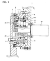
- Fig. 1 shows a cross-sectional view of an essential part of gear transmission I of the present embodiment.
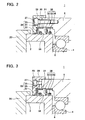
- Fig. 2 shows an enlarged view of the region encompassed by dashed line A of Fig. 1 .
- cross-hatching is omitted from some components.
- the gear transmission 1 will first be described in a summary manner.
- the gear transmission 1 is an eccentric oscillating-type speed reducer, and its basic configuration is well known. Consequently, the basic configuration of the gear transmission I will be briefly described.
- the gear transmission 1 comprises a carrier 2 and a case 6.
- the case 6 is equivalent to a first member
- the carrier 2 is equivalent to a second member.
- the carrier 2 is rotatably supported on the case 6 via a pair of angular ball bearings 4.
- the carrier 2 and the case 6 rotate relative to one another, and lubricant is sealed between the two.
- a groove that encircles the circumferential direction is formed in the carrier 2.
- the carrier 2 passes through a through-hole 31 (see Fig. 2 ) formed in the case 6, and one end of the carrier 2 (the left side end in Fig. 1 ) is exposed at the outside of the case 6.
- the through-hole 31 is equivalent to a circular hole.
- the carrier 2 comprises an external gear 10 and a crankshaft 12.
- the external gear 10 is supported so as to be capable of rotating eccentrically with respect to the carrier 2.
- the external gear 10 meshes with an internal gear formed on an inner circumferential surface of the case 6.
- Torque from a motor 16 is transmitted to the crankshaft 12 via a motor gear 14.
- An eccentric body 21 is affixed to the crankshaft 12. The eccentric body 21 engages with the external gear 10.
- the crankshaft 12 rotates
- the eccentric body 21 rotates eccentrically around the axis of the crankshaft 12. Consequently, the external gear 10 rotates eccentrically around the axis of the internal gear while meshing with the internal gear.
- the external gear 10 rotates eccentrically, the external gear 10 rotates with respect to the internal gear (the case 6) in accordance with the difference in the number of teeth of the external gear 10 and the internal gear.
- the carrier 2 rotates with respect to the case 6 together with the rotation of the external gear 10.
- the motor 16 and the case 6 are affixed to a base 18, and the carrier 2 is affixed to a rotating member 20. Consequently, the gear transmission 1 can rotate the rotating member 20 with respect to the base 18.
- lubricant is enclosed in the gear transmission 1.
- a lubricant enclosure space 8 is formed in the interior of the case 6.
- One end of the carrier 2 is exposed from the case 6 to the outside. Consequently, an oil seal is positioned between the case 6 and the carrier 2 so that the lubricant does not leak from the lubricant enclosure space 8 to the outside of the gear transmission 1.
- a first sealing body 36 and a second sealing body 26 are positioned between the case 6 and the carrier 2.
- the second sealing body 26 is placed at a position on the opposite side of the lubricant enclosure space 8 and the first sealing body 36 is interposed therebetween.
- the first sealing body 36 comprises a main oil seal 34 and a first dust seal 32, which are integrally formed.
- the second sealing body 26 comprises a secondary oil seal 24 and a second dust seal 22, which are integrally formed.
- the secondary oil seal 24 is placed at a position on the opposite side of the lubricant enclosure space 8 and the main oil seal 34 is interposed therebetween.
- the second dust seal 22 is placed at a positioned on the opposite side of the lubricant enclosure space 8 and the secondary oil seal 24 is interposed therebetween. Moreover, the second dust seal 22 can also be said to be placed at a position on the opposite side of the main oil seal 34 and the secondary oil seal 24 is interposed therebetween.
- the first sealing body 36 and the second sealing body 26 have the same shape (the same specifications).
- the sealing bodies 36, 26 are typically called “oil seals”.
- the oil seals 34, 24 are called “lip portions (or main lips)” and the dust seals 32, 22 are called “dust lip portions (or auxiliary lips)”. That is, the "lip portion” and the “dust lip portion” together may be called the "oil seal”.
- oil seals without the "dust lip portion” also exist.
- the part typically called the "lip portion” is termed the oil seal
- the part typically called the “dust lip portion” is termed the dust seal
- the part typically called the “oil seal” is termed the sealing body.
- the first sealing body 36 is attached via a fitting portion 33 to an inner circumferential surface of the through-hole 31 of the case 6. Accordingly, the main oil seal 34 is inserted into the inner circumferential surface of the through-hole 31 of the case 6.
- the inner circumferential surface of the main oil seal 34 constantly contacts the carrier 2. Oil is prevented from leaking from the lubricant enclosure space 8 to the outside of the gear transmission 1 by the main oil seal 34. That is, the lubricant is sealed within the gear transmission 1 by the main oil seal 34.
- the first dust seal 32 will be described later.
- the second sealing body 26 is attached via a fitting portion 23 to a support member 28. Since the support member 28 is attached to the case 6 by a bolt 30, the secondary oil seal 24 (the second sealing body 26) can be said to be attached to the case 6 via the support member 28.
- the secondary oil seal 24 is positioned at a position (reserve position) opposing a groove 38 that is formed encircling the circumferential direction of the carrier 2. In the reserve position, the inner circumferential surface of the secondary oil seal 24 does not contact the carrier 2. The secondary oil seal 24 moves along the axis of the carrier 2. The movement of the secondary oil seal 24 will be described later.
- Fig. 3 shows a cross-sectional view of the portion encompassed by dashed line A of Fig. 1 as viewed from a cross-section different from Fig. 1 .
- a spacer bolt 40 is fastened to the support member 28.
- the tip of the spacer bolt 40 contacts the case 6, thereby forming a gap 27 between the support member 28 and the case 6.
- the position of the second sealing body 26 is fixed by the bolt 30 (see Fig. 2 ) and the spacer bolt 40.
- the secondary oil seal 24 is positioned at a position (reserve position) opposing the groove 38 without the inner circumferential surface of the secondary oil seal 24 making contact with the carrier 2.
- a plurality of the bolts 30 and spacer bolts 40 are attached in the circumferential direction of the gear transmission 1. Consequently, the gap 27 is retained at a constant width around the entire circumferential direction of the gear transmission 1.
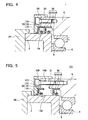
- FIG. 4 shows the situation, in which the secondary oil seal is positioned at the sealing position. As shown in Fig. 4 , the secondary oil seal 24 and the second dust seal 22 move in the axial direction of the carrier 2. When the secondary oil seal 24 has moved to the sealing position, the second dust seal 22 is placed at a position on the opposite side of the lubricant enclosure space 8 and the groove 38 is interposed therebetween. At both the reserve position and the sealing position, the inner circumferential surface of the second dust seal 22 constantly contacts the carrier 2.
- the carrier 2 rotates relative to the case 6. Consequently, when the main oil seal 34 is used a long time, the main oil seal 34 deteriorates due to abrasion, and the sealing performance between the main oil seal 34 and the carrier 2 can no longer be maintained.
- the secondary oil seal 24 is moved from the reserve position to the sealing position. Oil can be prevented from leaking from the lubricant enclosure space 8 by the inner circumferential surface of the secondary oil seal 24 contacting the carrier 2.
- the sealing performance of the secondary oil seal 24 and the carrier 2 will be reduced if foreign material is trapped between the secondary oil seal 24 and the carrier 2.
- the service life of the secondary oil seal 24 will be shortened.
- the second dust seal 22 is attached at a position on the opposite side of the main oil seal 34 and the secondary oil seal 24 is interposed therebetween. Consequently, it is possible to prevent foreign material entering from the outside and adhering to the inner circumferential surface of the secondary oil seal 24. Alternatively, the ingress of foreign material between the main oil seal 34 and the secondary oil seal 24 can be prevented.
- the sealing performance of the secondary oil seal 24 and the carrier 2 is maintained.
- the sealing performance of the gear transmission I can be maintained over a long period.
- the first dust seal 32 is formed integrally with the main oil seal 34 on the opposite side of the lubricant enclosure space 8 and the main oil seal 34 is interposed therebetween. Consequently, the first dust seal 32 is positioned between the main oil seal 34 and the secondary oil seal 24. Even if the main oil seal 34 abrades, its abrasion powder is prevented by the first dust seal 32 from migrating between the first dust seal 32 and the secondary oil seal 24. The abrasion powder originating from the main oil seal 34 is prevented from being trapped between the secondary oil seal 24 and the carrier 2.
- the gear transmission 1 comprises the dust seals 32, 22 both between the secondary oil seal 24 and the main oil seal 34, and between the secondary oil seal 24 and the outside (opposite side of the main oil seal 34 with the secondary oil seal 24 interposed therebetween) of the gear transmission 1.
- the abrasion powder from the main oil seal 34 cannot be counteracted only by positioning the dust seal 22 between the secondary oil seal 24 and the outside of the gear transmission 1.
- the secondary oil seal 24 and the second dust seal 22 integrally form the second sealing body 26. Consequently, the number of components of the gear transmission I can be reduced. Further, the manufacturing process of the gear transmission 1 can be made simpler than in the case where the secondary oil seal 24 and the second dust seal 22 are attached separately to the support member 28 (or the case 6).
- the second dust seal 22 When the secondary oil seal 24 has been moved to the sealing position, the second dust seal 22 is positioned on the opposite side of the lubricant enclosure space 8 and the groove 38 is interposed therebetween (see Fig. 4 ). Stated more specifically, while the secondary oil seal 24 is moving, the second dust seal 22 continues to make contact with the carrier 2 without ever opposing the groove 38. The secondary oil seal 24 can be moved without a concern that a gap will occur between the second dust seal 22 and the carrier 2. Consequently, the secondary oil seal 24 may simply be moved to a position (the sealing position) that does not oppose the groove 38. The amount of movement of the secondary oil seal 24 can be minimized.
- a portion of the support member 28 overlaps with the outer circumferential surface of the case 6 as viewed along the radial direction of the gear transmission 1. Since the support member 28 and the case 6 overlap, the support member 28 can move smoothly when the secondary oil seal 24 is moved to the sealing position. Only a narrow gap exists between the portion of the support member 28 and the outer circumferential surface of the case 6. Consequently, the support member 28 can move smoothly, and the ingress of large foreign material into the gap 27 from the outside of the gear transmission 1 can be prevented.
- the outer circumferential surface of the second sealing body 26 (the outer circumferential surface of the fitting part 23) contacts both the support member 28 and the case 6 in the radial direction. Consequently, the gap 27 and the secondary oil seal 24 are separated. Therefore, minute foreign material, which has entered the gap 27 from the gap of the overlapping portions of the support member 28 and the outer circumferential surface of the case 6, can be prevented from reaching the secondary oil seal 24. The foreign material can be reliably prevented from adhering to the inner circumferential surface of the secondary oil seal 24.
- the outer circumferential surface of the fitting part 23 of the second sealing body 26 is formed from the same resilient material as the secondary oil seal 24, etc.
- Gear transmission 101 of the present embodiment will be described with reference to Figs. 5 to 7 .
- the gear transmission 101 of the present embodiment differs from the gear transmission 1 of the first embodiment only in the region encompassed by dashed line A (see Fig. 1 ). Consequently, in Figs. 5 to 7 , only the region corresponding to dashed line A of the gear transmission I is shown. Further, the same reference number or a reference number having the same two lower digits may be applied to a component that is in common with that of the above-described gear transmission 1, and an explanation thereof may be omitted.
- the second dust seal 22 moves from a position, at which it contacts the carrier 2 on the opposite side of the lubricant enclosure space 8 and the groove 138 is interposed therebetween, passes over the groove 138, and then moves to a position at which it makes contact with the carrier 2 closer to the lubricant enclosure space 8 side than the groove 138. Consequently, in the gear transmission 101, the displacement distance of the second sealing body 26 is longer than in the gear transmission 1. Since a spacer bolt 140 (see Fig. 6 ), which is longer than the spacer bolt 40 of the gear transmission 1, is used in the gear transmission 101, the displacement distance of the second sealing body 26 is longer than in the gear transmission 1.
- the manufacturing precision of the groove 38 and the positioning precision of the reserve position and the sealing position must be tightly controlled.
- the width of the groove 38 (the length in the axial direction of the carrier 2) is too large, the second dust seal 22 will oppose the groove 38 when the secondary oil seal 24 has been moved to the sealing position.
- the second dust seal 22 will also oppose the groove 38, if the positioning precision of the reserve position and the sealing position is not tightly controlled. The second dust seal 22 can no longer continue to make contact with the carrier 2.
- the second dust seal 22 may be merely positioned closer to the lubricant enclosure space 8 side than the groove 138. Consequently, the manufacturing precision of the groove 138, and the positioning precision of the reserve position and the sealing position need not be tightly controlled.
- the spacer bolt 140 By merely making the spacer bolt 140 longer than the spacer bolt 40 of the gear transmission I, the second dust seal 22 can reliably contact the carrier 2 when the secondary oil seal 24 has been moved to the sealing position.
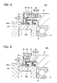
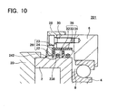
- Gear transmission 201 will be described with reference to Figs. 8 to 10 .
- the gear transmission 201 differs from the gear transmission 1 of the first embodiment only in the region encompassed by dashed line A of Fig. 1 . Consequently, in Figs. 8 to 10 , only the region corresponding to dashed line A of the gear transmission 1 is shown. Further, the same reference number or a reference number having the same two lower digits may be applied to a component that is in common with that of the above-described gear transmission 1, and an explanation thereof may be omitted.
- a third dust seal 242 is attached to the support member 28 on the opposite side of the lubricant enclosure space 8 and the second sealing body 26 is interposed therebetween; the third dust seal 242 contacts the carrier 2. Therefore, the third dust seal 242 is not formed integrally with the secondary oil seal 24.
- the width of a groove 238 (the length in the axial direction of the carrier 2) is larger than the width of the groove 38. Consequently, in the gear transmission 201, when the secondary oil seal 24 is positioned at the reserve position (see Fig. 8 ), the second dust seal 22 opposes the groove 238. Therefore, the second dust seal 22 does not contact the carrier 2.
- the third dust seal 242 contacts the carrier 2, foreign material can be prevented from adhering to the inner circumferential surface of the secondary oil seal 24, and can be prevented from entering between the secondary oil seal 24 and the main oil seal 34. Moreover, the third dust seal 242 contacts the carrier even when the secondary oil seal 24 moves to the sealing position (see Fig. 10 ).
- the bolt 30 and the spacer bolt 40 utilized in the gear transmission 201 are identical to those utilized in the gear transmission 1. Consequently, the displacement distance of the secondary oil seal 24 is also identical.
- the displacement distance of the secondary oil seal 24 cannot be increased (see Figs. 5 , 7 ). Consequently, if the width of the groove 238 becomes larger, the second dust seal 22 will no longer contact the carrier 2. Foreign material will be trapped between the secondary oil seal 24 and the carrier 2. Since the third dust seal 242 is disposed in the gear transmission 201, ingress of foreign material can be prevented even if the width of the groove 238 becomes larger.
- the inner circumferential surface of the second dust seal 22 may contact the carrier 2. After the secondary oil seal 24 has been moved to the sealing position, the inner circumferential surface of the second dust seal 22 may contact the carrier 2.
- the characterizing feature of the gear transmission 201 is that the third dust seal 242 can prevent the ingress of foreign material even if the second dust seal 22 can not make contact with the carrier 2.
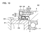
- Gear transmission 301 will be described with reference to Figs. 11 to 13 .
- the gear transmission 301 differs from the gear transmission 1 of the first embodiment only in the region encompassed by dashed line A of Fig. 1 . Consequently, in Figs. 11 to 13 , only the region corresponding to dashed line A of the gear transmission 1 is shown. Further, the same reference number or a reference number having the same two lower digits may be applied to a component that is in common with that of the gear transmission 1, and an explanation thereof may be omitted.
- a third dust seal 342 is attached to a support member 328 on the opposite side of the lubricant enclosure space 8 and the second sealing body 26 is interposed therebetween.
- the gear transmission 301 has the same characterizing feature as the gear transmission 201. Comparing the gear transmission 301 and the gear transmission 201, a bolt 330 and a spacer bolt 340 are longer than the bolt 30 and the spacer bolt 40 (see also Figs. 8, 9 ). Therefore, in the gear transmission 301, the displacement distance of the second sealing body 26 and the third dust seal 342 is longer than in the gear transmission 201.
- the gear transmission 301 when the secondary oil seal 24 is positioned in the reserve position, the third dust seal 342 contacts the carrier 2, and the second dust seal 22 does not contact the carrier 2.
- the second dust seal 22 makes contact with the carrier 2, and the third dust seal 342 does not contact the carrier 2 (see Fig. 13 ).
- Different dust seals contact the carrier 2 before and after the secondary oil seal 24 moves from the reserve position to the sealing position.
- the gear transmission 301 can also be said to be provided with a secondary dust seal (the dust seal 22). After the secondary oil seal 24 has been moved to the sealing position, a dust seal that is not deteriorated can be made to contact the carrier 2.
- the main oil seal, the secondary oil seal and the dust seal are all attached to the case.
- the main oil seal, secondary oil seal and dust seal may all be attached to the carrier.
- the main oil seal, secondary oil seal and dust seal may each be attached to either the carrier or the case.
- the groove is formed in the carrier.
- the groove can be formed in the inner circumferential surface of the through-hole (circular hole) of the case.
- the secondary oil seal may be attached to whichever of the carrier and the case does not have the groove formed therein.
- only one main oil seal is disposed between the case and the carrier.
- Two or more main oil seals may be disposed.
- two or more secondary oil seals may be disposed. Oil leakage from the apparatus with a seal can be prevented more reliably.
- the other secondary oil seal(s) when one secondary oil seal has been moved to the sealing position, the other secondary oil seal(s) may be positioned at the reserve position. Stated more specifically, when one secondary oil seal has contacted the carrier, the other secondary oil seal(s) may not make contact with the carrier. When the one secondary oil seal has deteriorated, oil leakage can be prevented by utilizing the other secondary oil seal(s). The service life of the apparatus with the seal can be further extended.
- the main oil seal and the first dust seal are integrally formed.
- the first dust seal may be separate from the main oil seal. In this case, when the secondary oil seal has been moved to the sealing position, the first dust seal may be placed at a position that does not make contact with the secondary oil seal. Further, if the second dust seal is attached on the opposite side of the lubricant enclosure space and the secondary oil seal is interposed therebetween, the secondary oil seal and the second dust seal need not be integrally formed.
Landscapes
- Engineering & Computer Science (AREA)
- General Engineering & Computer Science (AREA)
- Mechanical Engineering (AREA)
- Sealing Devices (AREA)
- Sealing Of Bearings (AREA)
- Sealing With Elastic Sealing Lips (AREA)
- General Details Of Gearings (AREA)
Claims (6)
- Vorrichtung mit einer Dichtung (1,101,201,301), die ein Schmiermittel zwischen zwei Elementen abdichtet, die sich relativ zueinander drehen, wobei die Vorrichtung (1,101,201,301) aufweist:ein erstes Element (6) mit einem kreisförmigen Loch (31);ein zweites Element (2), das durch das kreisförmige Loch (31) geht und konfiguriert ist, sich relativ zum ersten Element (6) zu drehen;eine Hauptöldichtung (34), die das Schmiermittel abdichtet und zwischen einer Innenumfangsfläche des kreisförmigen Lochs (31) und dem zweiten Element (2) eingefügt ist;eine Sekundäröldichtung (24), die längs einer Mittellinie des kreisförmigen Lochs (31) beweglich ist und auf einer gegenüberliegenden Seite des Schmiermittels angeordnet ist, wobei die Hauptöldichtung (34) dazwischen angeordnet ist;eine Staubdichtung (22,242,342), die auf einer gegenüberliegenden Seite des Schmiermittels angeordnet ist, wobei die Sekundäröldichtung (24) dazwischen angeordnet ist;wobei eine in Umfangsrichtung umgebende Nut (38,138,238,338) auf der Innenumfangsfläche des kreisförmigen Lochs (31) oder einer Außenumfangsfläche des zweiten Elements (2) ausgebildet ist, und die Nut (38,138,238,338) auf der gegenüberliegenden Seite des Schmiermittels angeordnet ist, wobei die Hauptöldichtung (34) dazwischen angeordnet ist,wobei die Sekundäröldichtung (24) von einer Reserveposition, in der die Sekundäröldichtung (24) der Nut (38,138,238,338) gegenüberliegt und das Element nicht berührt, das mit der Nut (38,138,238,338) ausgebildet ist, zu einer Dichtungsposition beweglich ist, in der die Sekundäröldichtung (24) der Nut (38,138,238,338) nicht gegenüberliegt und das Element berührt, das mit der Nut (38,138,238,338) ausgebildet ist, und die Staubdichtung (22,242,342) sowohl wenn die Sekundäröldichtung (24) in der Reserveposition angeordnet ist als auch wenn die Sekundäröldichtung (24) in der Dichtungsposition angeordnet ist, mit dem ersten Element (6) oder dem zweiten Element (2) gekoppelt ist und das andere des ersten Elements (6) und des zweiten Elements (2) berührt, ohne der Nut gegenüberzuliegen.
- Vorrichtung mit einer Dichtung nach Anspruch 1, wobei die Staubdichtung (22,242,342) mit der Sekundäröldichtung (24) verbunden ist und sich zusammen mit der Sekundäröldichtung (24) bewegt.
- Vorrichtung mit einer Dichtung nach Anspruch 2, wobei die Sekundäröldichtung (24) integral mit der Staubdichtung (22) ausgebildet ist.
- Vorrichtung mit einer Dichtung (1, 201) nach Anspruch 2 oder 3, wobei wenn sich die Sekundäröldichtung (24) zur Dichtungsposition bewegt, die Staubdichtung (22, 242) auf der gegenüberliegenden Seite des Schmiermittels angeordnet ist und die Nut (38,238) dazwischen angeordnet ist.
- Vorrichtung mit einer Dichtung (101, 301) nach Anspruch 2 oder 3, wobei wenn sich die Sekundäröldichtung (24) zur Dichtungsposition bewegt, die Staubdichtung (22) näher zu einer Schmiermittelseite angeordnet ist als die Nut (138,338).
- Vorrichtung mit einer Dichtung (1,101,201,301) nach einem der Ansprüche 1 bis 5, die ferner aufweist:eine zusätzliche Staubdichtung (32), die zwischen der Hauptöldichtung (34) und der Sekundäröldichtung (24) angeordnet ist.
Applications Claiming Priority (2)
| Application Number | Priority Date | Filing Date | Title |
|---|---|---|---|
| JP2008088583A JP5145099B2 (ja) | 2008-03-28 | 2008-03-28 | シール付き装置 |
| PCT/JP2009/056279 WO2009119801A1 (ja) | 2008-03-28 | 2009-03-27 | シール付き装置 |
Publications (3)
| Publication Number | Publication Date |
|---|---|
| EP2273140A1 EP2273140A1 (de) | 2011-01-12 |
| EP2273140A4 EP2273140A4 (de) | 2013-09-04 |
| EP2273140B1 true EP2273140B1 (de) | 2015-09-02 |
Family
ID=41113985
Family Applications (1)
| Application Number | Title | Priority Date | Filing Date |
|---|---|---|---|
| EP09724154.1A Active EP2273140B1 (de) | 2008-03-28 | 2009-03-27 | Vorrichtung mit dichtungen |
Country Status (5)
| Country | Link |
|---|---|
| US (1) | US20110012314A1 (de) |
| EP (1) | EP2273140B1 (de) |
| JP (1) | JP5145099B2 (de) |
| CN (1) | CN101981335B (de) |
| WO (1) | WO2009119801A1 (de) |
Families Citing this family (12)
| Publication number | Priority date | Publication date | Assignee | Title |
|---|---|---|---|---|
| KR101438253B1 (ko) * | 2010-06-29 | 2014-09-04 | 현대중공업 주식회사 | 스러스터용 다단인써트형 슬리브 장착 레디알 샤프트 씰장치 |
| JP2012057672A (ja) * | 2010-09-07 | 2012-03-22 | Sumitomo Heavy Ind Ltd | 回転装置のシリーズ、回転装置の追加ユニット、及び回転装置のシール装置 |
| FR2974532A1 (fr) * | 2011-04-27 | 2012-11-02 | Peugeot Citroen Automobiles Sa | Procede de remplacement d'un joint d'etancheite defectueux |
| CN102606740B (zh) * | 2011-11-28 | 2014-08-13 | 佛山市科达液压机械有限公司 | 旋转轴旋转密封结构 |
| US9010761B2 (en) * | 2012-10-31 | 2015-04-21 | Canrig Drilling Technology Ltd. | Redundant seal apparatus and method |
| WO2014202823A1 (en) * | 2013-06-19 | 2014-12-24 | Wärtsilä Finland Oy | Slewing seal arrangement for a steerable thruster |
| EP2993123B1 (de) * | 2014-09-02 | 2017-03-08 | ABB Oy | Dichtungsanordnung in einem Schiff |
| US9551413B2 (en) | 2014-09-25 | 2017-01-24 | Renold Plc | Lubricated gear coupling |
| KR102050892B1 (ko) * | 2018-09-21 | 2019-12-02 | 주식회사 케이티이 | 스러스터용 다단 레디알 샤프트 씰장치 |
| JP2022041209A (ja) * | 2020-08-31 | 2022-03-11 | ナブテスコ株式会社 | 減速機及び駆動装置 |
| JP2022154089A (ja) * | 2021-03-30 | 2022-10-13 | 津田駒工業株式会社 | 回転割出し装置 |
| EP4585833A1 (de) * | 2024-01-11 | 2025-07-16 | ABB Oy | Verfahren und anordnung zum abdichten einer antriebswelle eines wasserfahrzeugs |
Family Cites Families (27)
| Publication number | Priority date | Publication date | Assignee | Title |
|---|---|---|---|---|
| US133877A (en) * | 1872-12-10 | Improvement in freight-elevating trucks | ||
| PL76196B1 (de) * | 1970-06-10 | 1975-02-28 | ||
| US4008897A (en) * | 1973-09-28 | 1977-02-22 | Howaldtswerke-Deutsche Werft Aktiengesellschaft Hamburg Und Kiel | Seals for rotating shafts, especially for stern tube seals for ships |
| DE3610226C1 (en) * | 1986-03-26 | 1987-06-04 | Goetze Ag | Lip seal ring |
| JPS6361593U (de) * | 1986-10-13 | 1988-04-23 | ||
| FR2742837B1 (fr) * | 1995-12-21 | 1998-02-20 | Eurocopter France | Dispositif d'etancheite pour arbre tournant |
| US6315296B1 (en) * | 1997-09-25 | 2001-11-13 | Transcom, Inc. | Flangeless retrofittable severe duty seal for a shaft |
| CA2288230A1 (en) * | 1999-10-27 | 2001-04-27 | Thomas Wilson Ramsay | Multiple lip seal cartridge and adjustable sleeve |
| JP2002227793A (ja) * | 2001-01-31 | 2002-08-14 | Furukawa Co Ltd | ポンプの軸封装置 |
| CN2524015Y (zh) * | 2002-01-04 | 2002-12-04 | 陈文昌 | 油封 |
| JP4901156B2 (ja) * | 2005-08-11 | 2012-03-21 | ナブテスコ株式会社 | 減速装置 |
| JP2007046581A (ja) * | 2005-08-12 | 2007-02-22 | Komatsu Zenoah Co | ポンプ |
| CN2818933Y (zh) * | 2005-08-24 | 2006-09-20 | 徐利阳 | 聚四氟乙烯旋转轴唇形密封圈 |
| JP2007085530A (ja) * | 2005-09-26 | 2007-04-05 | Nabtesco Corp | 中空減速機 |
| EP1939602A4 (de) * | 2005-10-21 | 2016-02-17 | Nabtesco Corp | Einrichtung und system zur ausgabe von wartungsinformationen |
| CN2844554Y (zh) * | 2005-11-08 | 2006-12-06 | 慈兴集团有限公司 | 轴承用密封圈 |
| JP4903719B2 (ja) * | 2006-01-13 | 2012-03-28 | ナブテスコ株式会社 | 関節機構 |
| JP2007232089A (ja) * | 2006-03-01 | 2007-09-13 | Ntn Corp | 転がり軸受のシール構造 |
| US8323140B2 (en) * | 2006-06-13 | 2012-12-04 | Nabtesco Corporation | Reduction gear transmission |
| JP2006283981A (ja) * | 2006-07-07 | 2006-10-19 | Nabtesco Corp | 減速機 |
| US7594664B2 (en) * | 2006-08-29 | 2009-09-29 | Skf Usa Inc. | Seal with pyramid shaped formation |
| US7828300B2 (en) * | 2006-09-21 | 2010-11-09 | Nok Corporation | Sealing device for reciprocating shaft |
| JP2008088583A (ja) | 2006-09-29 | 2008-04-17 | Toray Ind Inc | 薄地織物用中空ナイロン繊維およびその製造方法、薄地織物 |
| KR101353172B1 (ko) * | 2006-09-29 | 2014-01-17 | 나부테스코 가부시키가이샤 | 감속 장치 |
| EP1927795A1 (de) * | 2006-11-28 | 2008-06-04 | Darwind Development & Demonstration BV | Öldichtungsvorrichtung |
| WO2009017143A1 (ja) * | 2007-07-31 | 2009-02-05 | Nabtesco Corporation | 歯車装置及び歯車装置を用いた産業用ロボットの旋回部構造 |
| TWM361579U (en) * | 2009-02-27 | 2009-07-21 | Chu Hung Oil Seals Ind Co Ltd | Hub oil seal |
-
2008
- 2008-03-28 JP JP2008088583A patent/JP5145099B2/ja active Active
-
2009
- 2009-03-27 CN CN200980111096.6A patent/CN101981335B/zh active Active
- 2009-03-27 EP EP09724154.1A patent/EP2273140B1/de active Active
- 2009-03-27 WO PCT/JP2009/056279 patent/WO2009119801A1/ja not_active Ceased
- 2009-03-27 US US12/933,932 patent/US20110012314A1/en not_active Abandoned
Also Published As
| Publication number | Publication date |
|---|---|
| CN101981335A (zh) | 2011-02-23 |
| EP2273140A4 (de) | 2013-09-04 |
| EP2273140A1 (de) | 2011-01-12 |
| WO2009119801A1 (ja) | 2009-10-01 |
| CN101981335B (zh) | 2014-06-25 |
| JP5145099B2 (ja) | 2013-02-13 |
| US20110012314A1 (en) | 2011-01-20 |
| JP2009243524A (ja) | 2009-10-22 |
Similar Documents
| Publication | Publication Date | Title |
|---|---|---|
| EP2273140A1 (de) | Vorrichtung mit dichtungen | |
| KR102379849B1 (ko) | 내부 시일을 갖는 스트레인 웨이브 기어 기구 | |
| CN101263319B (zh) | 偏心摆动型减速机 | |
| JP2001254787A (ja) | 減速機及びロボットの関節装置 | |
| KR102381750B1 (ko) | 감속장치 | |
| JP2014109323A (ja) | 歯車装置 | |
| JP2011174570A (ja) | 密封装置 | |
| JP2009085267A (ja) | 歯車装置 | |
| JP2008286357A (ja) | シール機構及びこれを備えた動力伝達装置 | |
| JP2009250279A (ja) | 減速機 | |
| JP2012229742A (ja) | 密封装置 | |
| JP2019183990A (ja) | 歯車装置 | |
| JP7227815B2 (ja) | 動力伝達装置 | |
| WO2022193061A1 (en) | Sealing component, gearbox and robot | |
| JP5143718B2 (ja) | 回転装置 | |
| JP4415600B2 (ja) | オイルシールによる密封構造 | |
| JP2010060120A (ja) | 密封装置 | |
| JP2017067268A (ja) | 密封装置 | |
| JP2021142929A (ja) | 車輪駆動装置 | |
| JP2010043679A (ja) | 減速装置及びその遊星歯車固定方法 | |
| JP7575152B1 (ja) | オイルシール | |
| JP4116298B2 (ja) | メカニカルシール | |
| US20190264796A1 (en) | Transmission and driving apparatus provided with transmission | |
| JP2021001630A (ja) | 密封構造 | |
| JP2005016627A (ja) | 密封装置 |
Legal Events
| Date | Code | Title | Description |
|---|---|---|---|
| PUAI | Public reference made under article 153(3) epc to a published international application that has entered the european phase |
Free format text: ORIGINAL CODE: 0009012 |
|
| 17P | Request for examination filed |
Effective date: 20101027 |
|
| AK | Designated contracting states |
Kind code of ref document: A1 Designated state(s): AT BE BG CH CY CZ DE DK EE ES FI FR GB GR HR HU IE IS IT LI LT LU LV MC MK MT NL NO PL PT RO SE SI SK TR |
|
| AX | Request for extension of the european patent |
Extension state: AL BA RS |
|
| DAX | Request for extension of the european patent (deleted) | ||
| A4 | Supplementary search report drawn up and despatched |
Effective date: 20130805 |
|
| RIC1 | Information provided on ipc code assigned before grant |
Ipc: F16J 15/00 20060101ALI20130730BHEP Ipc: F16J 15/32 20060101ALI20130730BHEP Ipc: F16C 33/78 20060101AFI20130730BHEP |
|
| GRAP | Despatch of communication of intention to grant a patent |
Free format text: ORIGINAL CODE: EPIDOSNIGR1 |
|
| INTG | Intention to grant announced |
Effective date: 20150313 |
|
| GRAS | Grant fee paid |
Free format text: ORIGINAL CODE: EPIDOSNIGR3 |
|
| GRAA | (expected) grant |
Free format text: ORIGINAL CODE: 0009210 |
|
| AK | Designated contracting states |
Kind code of ref document: B1 Designated state(s): AT BE BG CH CY CZ DE DK EE ES FI FR GB GR HR HU IE IS IT LI LT LU LV MC MK MT NL NO PL PT RO SE SI SK TR |
|
| REG | Reference to a national code |
Ref country code: GB Ref legal event code: FG4D |
|
| REG | Reference to a national code |
Ref country code: AT Ref legal event code: REF Ref document number: 746805 Country of ref document: AT Kind code of ref document: T Effective date: 20150915 Ref country code: CH Ref legal event code: EP |
|
| REG | Reference to a national code |
Ref country code: IE Ref legal event code: FG4D |
|
| REG | Reference to a national code |
Ref country code: DE Ref legal event code: R096 Ref document number: 602009033328 Country of ref document: DE |
|
| REG | Reference to a national code |
Ref country code: AT Ref legal event code: MK05 Ref document number: 746805 Country of ref document: AT Kind code of ref document: T Effective date: 20150902 |
|
| PG25 | Lapsed in a contracting state [announced via postgrant information from national office to epo] |
Ref country code: FI Free format text: LAPSE BECAUSE OF FAILURE TO SUBMIT A TRANSLATION OF THE DESCRIPTION OR TO PAY THE FEE WITHIN THE PRESCRIBED TIME-LIMIT Effective date: 20150902 Ref country code: GR Free format text: LAPSE BECAUSE OF FAILURE TO SUBMIT A TRANSLATION OF THE DESCRIPTION OR TO PAY THE FEE WITHIN THE PRESCRIBED TIME-LIMIT Effective date: 20151203 Ref country code: LT Free format text: LAPSE BECAUSE OF FAILURE TO SUBMIT A TRANSLATION OF THE DESCRIPTION OR TO PAY THE FEE WITHIN THE PRESCRIBED TIME-LIMIT Effective date: 20150902 Ref country code: LV Free format text: LAPSE BECAUSE OF FAILURE TO SUBMIT A TRANSLATION OF THE DESCRIPTION OR TO PAY THE FEE WITHIN THE PRESCRIBED TIME-LIMIT Effective date: 20150902 Ref country code: NO Free format text: LAPSE BECAUSE OF FAILURE TO SUBMIT A TRANSLATION OF THE DESCRIPTION OR TO PAY THE FEE WITHIN THE PRESCRIBED TIME-LIMIT Effective date: 20151202 |
|
| REG | Reference to a national code |
Ref country code: LT Ref legal event code: MG4D Ref country code: NL Ref legal event code: MP Effective date: 20150902 |
|
| PG25 | Lapsed in a contracting state [announced via postgrant information from national office to epo] |
Ref country code: SE Free format text: LAPSE BECAUSE OF FAILURE TO SUBMIT A TRANSLATION OF THE DESCRIPTION OR TO PAY THE FEE WITHIN THE PRESCRIBED TIME-LIMIT Effective date: 20150902 Ref country code: PL Free format text: LAPSE BECAUSE OF FAILURE TO SUBMIT A TRANSLATION OF THE DESCRIPTION OR TO PAY THE FEE WITHIN THE PRESCRIBED TIME-LIMIT Effective date: 20150902 Ref country code: AT Free format text: LAPSE BECAUSE OF FAILURE TO SUBMIT A TRANSLATION OF THE DESCRIPTION OR TO PAY THE FEE WITHIN THE PRESCRIBED TIME-LIMIT Effective date: 20150902 Ref country code: ES Free format text: LAPSE BECAUSE OF FAILURE TO SUBMIT A TRANSLATION OF THE DESCRIPTION OR TO PAY THE FEE WITHIN THE PRESCRIBED TIME-LIMIT Effective date: 20150902 |
|
| PG25 | Lapsed in a contracting state [announced via postgrant information from national office to epo] |
Ref country code: IT Free format text: LAPSE BECAUSE OF FAILURE TO SUBMIT A TRANSLATION OF THE DESCRIPTION OR TO PAY THE FEE WITHIN THE PRESCRIBED TIME-LIMIT Effective date: 20150902 Ref country code: NL Free format text: LAPSE BECAUSE OF FAILURE TO SUBMIT A TRANSLATION OF THE DESCRIPTION OR TO PAY THE FEE WITHIN THE PRESCRIBED TIME-LIMIT Effective date: 20150902 Ref country code: EE Free format text: LAPSE BECAUSE OF FAILURE TO SUBMIT A TRANSLATION OF THE DESCRIPTION OR TO PAY THE FEE WITHIN THE PRESCRIBED TIME-LIMIT Effective date: 20150902 Ref country code: CZ Free format text: LAPSE BECAUSE OF FAILURE TO SUBMIT A TRANSLATION OF THE DESCRIPTION OR TO PAY THE FEE WITHIN THE PRESCRIBED TIME-LIMIT Effective date: 20150902 Ref country code: SK Free format text: LAPSE BECAUSE OF FAILURE TO SUBMIT A TRANSLATION OF THE DESCRIPTION OR TO PAY THE FEE WITHIN THE PRESCRIBED TIME-LIMIT Effective date: 20150902 Ref country code: IS Free format text: LAPSE BECAUSE OF FAILURE TO SUBMIT A TRANSLATION OF THE DESCRIPTION OR TO PAY THE FEE WITHIN THE PRESCRIBED TIME-LIMIT Effective date: 20160102 |
|
| PG25 | Lapsed in a contracting state [announced via postgrant information from national office to epo] |
Ref country code: RO Free format text: LAPSE BECAUSE OF FAILURE TO SUBMIT A TRANSLATION OF THE DESCRIPTION OR TO PAY THE FEE WITHIN THE PRESCRIBED TIME-LIMIT Effective date: 20150902 Ref country code: PT Free format text: LAPSE BECAUSE OF FAILURE TO SUBMIT A TRANSLATION OF THE DESCRIPTION OR TO PAY THE FEE WITHIN THE PRESCRIBED TIME-LIMIT Effective date: 20160104 |
|
| REG | Reference to a national code |
Ref country code: DE Ref legal event code: R097 Ref document number: 602009033328 Country of ref document: DE |
|
| PLBE | No opposition filed within time limit |
Free format text: ORIGINAL CODE: 0009261 |
|
| STAA | Information on the status of an ep patent application or granted ep patent |
Free format text: STATUS: NO OPPOSITION FILED WITHIN TIME LIMIT |
|
| 26N | No opposition filed |
Effective date: 20160603 |
|
| PG25 | Lapsed in a contracting state [announced via postgrant information from national office to epo] |
Ref country code: DK Free format text: LAPSE BECAUSE OF FAILURE TO SUBMIT A TRANSLATION OF THE DESCRIPTION OR TO PAY THE FEE WITHIN THE PRESCRIBED TIME-LIMIT Effective date: 20150902 Ref country code: BE Free format text: LAPSE BECAUSE OF NON-PAYMENT OF DUE FEES Effective date: 20160331 Ref country code: SI Free format text: LAPSE BECAUSE OF FAILURE TO SUBMIT A TRANSLATION OF THE DESCRIPTION OR TO PAY THE FEE WITHIN THE PRESCRIBED TIME-LIMIT Effective date: 20150902 |
|
| PG25 | Lapsed in a contracting state [announced via postgrant information from national office to epo] |
Ref country code: LU Free format text: LAPSE BECAUSE OF FAILURE TO SUBMIT A TRANSLATION OF THE DESCRIPTION OR TO PAY THE FEE WITHIN THE PRESCRIBED TIME-LIMIT Effective date: 20160327 Ref country code: MC Free format text: LAPSE BECAUSE OF FAILURE TO SUBMIT A TRANSLATION OF THE DESCRIPTION OR TO PAY THE FEE WITHIN THE PRESCRIBED TIME-LIMIT Effective date: 20150902 |
|
| REG | Reference to a national code |
Ref country code: CH Ref legal event code: PL |
|
| GBPC | Gb: european patent ceased through non-payment of renewal fee |
Effective date: 20160327 |
|
| REG | Reference to a national code |
Ref country code: IE Ref legal event code: MM4A |
|
| PG25 | Lapsed in a contracting state [announced via postgrant information from national office to epo] |
Ref country code: BE Free format text: LAPSE BECAUSE OF FAILURE TO SUBMIT A TRANSLATION OF THE DESCRIPTION OR TO PAY THE FEE WITHIN THE PRESCRIBED TIME-LIMIT Effective date: 20150902 |
|
| REG | Reference to a national code |
Ref country code: FR Ref legal event code: ST Effective date: 20161130 |
|
| PG25 | Lapsed in a contracting state [announced via postgrant information from national office to epo] |
Ref country code: IE Free format text: LAPSE BECAUSE OF NON-PAYMENT OF DUE FEES Effective date: 20160327 Ref country code: FR Free format text: LAPSE BECAUSE OF NON-PAYMENT OF DUE FEES Effective date: 20160331 Ref country code: LI Free format text: LAPSE BECAUSE OF NON-PAYMENT OF DUE FEES Effective date: 20160331 Ref country code: GB Free format text: LAPSE BECAUSE OF NON-PAYMENT OF DUE FEES Effective date: 20160327 Ref country code: CH Free format text: LAPSE BECAUSE OF NON-PAYMENT OF DUE FEES Effective date: 20160331 |
|
| PG25 | Lapsed in a contracting state [announced via postgrant information from national office to epo] |
Ref country code: MT Free format text: LAPSE BECAUSE OF FAILURE TO SUBMIT A TRANSLATION OF THE DESCRIPTION OR TO PAY THE FEE WITHIN THE PRESCRIBED TIME-LIMIT Effective date: 20150902 |
|
| PG25 | Lapsed in a contracting state [announced via postgrant information from national office to epo] |
Ref country code: CY Free format text: LAPSE BECAUSE OF FAILURE TO SUBMIT A TRANSLATION OF THE DESCRIPTION OR TO PAY THE FEE WITHIN THE PRESCRIBED TIME-LIMIT Effective date: 20150902 Ref country code: HU Free format text: LAPSE BECAUSE OF FAILURE TO SUBMIT A TRANSLATION OF THE DESCRIPTION OR TO PAY THE FEE WITHIN THE PRESCRIBED TIME-LIMIT; INVALID AB INITIO Effective date: 20090327 |
|
| PG25 | Lapsed in a contracting state [announced via postgrant information from national office to epo] |
Ref country code: MT Free format text: LAPSE BECAUSE OF FAILURE TO SUBMIT A TRANSLATION OF THE DESCRIPTION OR TO PAY THE FEE WITHIN THE PRESCRIBED TIME-LIMIT Effective date: 20160331 Ref country code: TR Free format text: LAPSE BECAUSE OF FAILURE TO SUBMIT A TRANSLATION OF THE DESCRIPTION OR TO PAY THE FEE WITHIN THE PRESCRIBED TIME-LIMIT Effective date: 20150902 Ref country code: MK Free format text: LAPSE BECAUSE OF FAILURE TO SUBMIT A TRANSLATION OF THE DESCRIPTION OR TO PAY THE FEE WITHIN THE PRESCRIBED TIME-LIMIT Effective date: 20150902 Ref country code: HR Free format text: LAPSE BECAUSE OF FAILURE TO SUBMIT A TRANSLATION OF THE DESCRIPTION OR TO PAY THE FEE WITHIN THE PRESCRIBED TIME-LIMIT Effective date: 20150902 |
|
| PG25 | Lapsed in a contracting state [announced via postgrant information from national office to epo] |
Ref country code: BG Free format text: LAPSE BECAUSE OF FAILURE TO SUBMIT A TRANSLATION OF THE DESCRIPTION OR TO PAY THE FEE WITHIN THE PRESCRIBED TIME-LIMIT Effective date: 20150902 |
|
| P01 | Opt-out of the competence of the unified patent court (upc) registered |
Effective date: 20230615 |
|
| PGFP | Annual fee paid to national office [announced via postgrant information from national office to epo] |
Ref country code: DE Payment date: 20260319 Year of fee payment: 18 |