EP2266521A1 - Plastikampulle und farbiger plastikbehälter - Google Patents
Plastikampulle und farbiger plastikbehälter Download PDFInfo
- Publication number
- EP2266521A1 EP2266521A1 EP08722164A EP08722164A EP2266521A1 EP 2266521 A1 EP2266521 A1 EP 2266521A1 EP 08722164 A EP08722164 A EP 08722164A EP 08722164 A EP08722164 A EP 08722164A EP 2266521 A1 EP2266521 A1 EP 2266521A1
- Authority
- EP
- European Patent Office
- Prior art keywords
- drug solution
- layer
- colored
- plastic
- discharge tube
- Prior art date
- Legal status (The legal status is an assumption and is not a legal conclusion. Google has not performed a legal analysis and makes no representation as to the accuracy of the status listed.)
- Granted
Links
- 229920003023 plastic Polymers 0.000 title claims abstract description 370
- 239000004033 plastic Substances 0.000 title claims abstract description 370
- 239000003708 ampul Substances 0.000 title claims abstract description 239
- 239000010410 layer Substances 0.000 claims abstract description 518
- 239000003814 drug Substances 0.000 claims abstract description 291
- 229940079593 drug Drugs 0.000 claims abstract description 291
- 238000003860 storage Methods 0.000 claims abstract description 129
- -1 cyclic olefin Chemical class 0.000 claims abstract description 114
- 239000000463 material Substances 0.000 claims abstract description 107
- 229920001577 copolymer Polymers 0.000 claims abstract description 61
- JRZJOMJEPLMPRA-UHFFFAOYSA-N olefin Natural products CCCCCCCC=C JRZJOMJEPLMPRA-UHFFFAOYSA-N 0.000 claims abstract description 44
- 239000012790 adhesive layer Substances 0.000 claims abstract description 34
- 230000009477 glass transition Effects 0.000 claims abstract description 18
- 238000004891 communication Methods 0.000 claims abstract description 8
- 239000006097 ultraviolet radiation absorber Substances 0.000 claims description 80
- 239000000049 pigment Substances 0.000 claims description 76
- 229920005989 resin Polymers 0.000 claims description 62
- 239000011347 resin Substances 0.000 claims description 62
- 229920001169 thermoplastic Polymers 0.000 claims description 46
- 239000004416 thermosoftening plastic Substances 0.000 claims description 46
- 238000000034 method Methods 0.000 claims description 43
- 229920000089 Cyclic olefin copolymer Polymers 0.000 claims description 37
- 229920000573 polyethylene Polymers 0.000 claims description 36
- 239000004698 Polyethylene Substances 0.000 claims description 34
- 230000003014 reinforcing effect Effects 0.000 claims description 30
- 238000002834 transmittance Methods 0.000 claims description 29
- 239000004743 Polypropylene Substances 0.000 claims description 23
- 229920001155 polypropylene Polymers 0.000 claims description 23
- 229920001903 high density polyethylene Polymers 0.000 claims description 18
- 239000004700 high-density polyethylene Substances 0.000 claims description 18
- 230000002093 peripheral effect Effects 0.000 claims description 18
- 239000012964 benzotriazole Substances 0.000 claims description 17
- 229920005673 polypropylene based resin Polymers 0.000 claims description 15
- 239000011859 microparticle Substances 0.000 claims description 14
- 229920001971 elastomer Polymers 0.000 claims description 12
- 239000000806 elastomer Substances 0.000 claims description 12
- 229910044991 metal oxide Inorganic materials 0.000 claims description 12
- 150000004706 metal oxides Chemical class 0.000 claims description 11
- 239000002667 nucleating agent Substances 0.000 claims description 9
- 239000003086 colorant Substances 0.000 claims description 6
- 238000009833 condensation Methods 0.000 claims description 5
- 230000005494 condensation Effects 0.000 claims description 5
- 239000000203 mixture Substances 0.000 claims description 5
- 125000003354 benzotriazolyl group Chemical group N1N=NC2=C1C=CC=C2* 0.000 claims description 3
- 238000013329 compounding Methods 0.000 abstract description 18
- 238000010828 elution Methods 0.000 abstract description 6
- 239000004615 ingredient Substances 0.000 abstract description 5
- 230000015572 biosynthetic process Effects 0.000 abstract description 4
- 239000000243 solution Substances 0.000 description 262
- 230000000052 comparative effect Effects 0.000 description 66
- 102100025634 Caspase recruitment domain-containing protein 16 Human genes 0.000 description 31
- 229920000642 polymer Polymers 0.000 description 31
- 108060001826 COP1 Proteins 0.000 description 30
- 229920000098 polyolefin Polymers 0.000 description 26
- 230000002349 favourable effect Effects 0.000 description 20
- 238000005259 measurement Methods 0.000 description 20
- 239000000126 substance Substances 0.000 description 20
- 229950003837 ozagrel Drugs 0.000 description 19
- SHZKQBHERIJWAO-AATRIKPKSA-N ozagrel Chemical compound C1=CC(/C=C/C(=O)O)=CC=C1CN1C=NC=C1 SHZKQBHERIJWAO-AATRIKPKSA-N 0.000 description 19
- 239000007864 aqueous solution Substances 0.000 description 17
- 230000000740 bleeding effect Effects 0.000 description 17
- 229940063583 high-density polyethylene Drugs 0.000 description 16
- VGGSQFUCUMXWEO-UHFFFAOYSA-N Ethene Chemical compound C=C VGGSQFUCUMXWEO-UHFFFAOYSA-N 0.000 description 15
- 239000005977 Ethylene Substances 0.000 description 15
- 230000000903 blocking effect Effects 0.000 description 15
- VZSRBBMJRBPUNF-UHFFFAOYSA-N 2-(2,3-dihydro-1H-inden-2-ylamino)-N-[3-oxo-3-(2,4,6,7-tetrahydrotriazolo[4,5-c]pyridin-5-yl)propyl]pyrimidine-5-carboxamide Chemical compound C1C(CC2=CC=CC=C12)NC1=NC=C(C=N1)C(=O)NCCC(N1CC2=C(CC1)NN=N2)=O VZSRBBMJRBPUNF-UHFFFAOYSA-N 0.000 description 14
- QRUDEWIWKLJBPS-UHFFFAOYSA-N benzotriazole Chemical compound C1=CC=C2N[N][N]C2=C1 QRUDEWIWKLJBPS-UHFFFAOYSA-N 0.000 description 14
- 230000000694 effects Effects 0.000 description 14
- 239000002504 physiological saline solution Substances 0.000 description 14
- 238000004519 manufacturing process Methods 0.000 description 13
- 230000003405 preventing effect Effects 0.000 description 13
- XLOMVQKBTHCTTD-UHFFFAOYSA-N Zinc monoxide Chemical compound [Zn]=O XLOMVQKBTHCTTD-UHFFFAOYSA-N 0.000 description 12
- 230000001070 adhesive effect Effects 0.000 description 10
- 229920005678 polyethylene based resin Polymers 0.000 description 10
- 101100028962 Saccharomyces cerevisiae (strain ATCC 204508 / S288c) PDR1 gene Proteins 0.000 description 9
- 229920001684 low density polyethylene Polymers 0.000 description 9
- 239000004702 low-density polyethylene Substances 0.000 description 9
- VXNZUUAINFGPBY-UHFFFAOYSA-N 1-Butene Chemical compound CCC=C VXNZUUAINFGPBY-UHFFFAOYSA-N 0.000 description 8
- JFNLZVQOOSMTJK-KNVOCYPGSA-N norbornene Chemical compound C1[C@@H]2CC[C@H]1C=C2 JFNLZVQOOSMTJK-KNVOCYPGSA-N 0.000 description 8
- 238000007789 sealing Methods 0.000 description 8
- AFCARXCZXQIEQB-UHFFFAOYSA-N N-[3-oxo-3-(2,4,6,7-tetrahydrotriazolo[4,5-c]pyridin-5-yl)propyl]-2-[[3-(trifluoromethoxy)phenyl]methylamino]pyrimidine-5-carboxamide Chemical compound O=C(CCNC(=O)C=1C=NC(=NC=1)NCC1=CC(=CC=C1)OC(F)(F)F)N1CC2=C(CC1)NN=N2 AFCARXCZXQIEQB-UHFFFAOYSA-N 0.000 description 7
- QQONPFPTGQHPMA-UHFFFAOYSA-N Propene Chemical compound CC=C QQONPFPTGQHPMA-UHFFFAOYSA-N 0.000 description 7
- 238000000071 blow moulding Methods 0.000 description 7
- 229920002725 thermoplastic elastomer Polymers 0.000 description 7
- XLYOFNOQVPJJNP-UHFFFAOYSA-N water Substances O XLYOFNOQVPJJNP-UHFFFAOYSA-N 0.000 description 7
- YLZOPXRUQYQQID-UHFFFAOYSA-N 3-(2,4,6,7-tetrahydrotriazolo[4,5-c]pyridin-5-yl)-1-[4-[2-[[3-(trifluoromethoxy)phenyl]methylamino]pyrimidin-5-yl]piperazin-1-yl]propan-1-one Chemical compound N1N=NC=2CN(CCC=21)CCC(=O)N1CCN(CC1)C=1C=NC(=NC=1)NCC1=CC(=CC=C1)OC(F)(F)F YLZOPXRUQYQQID-UHFFFAOYSA-N 0.000 description 6
- UQSXHKLRYXJYBZ-UHFFFAOYSA-N Iron oxide Chemical compound [Fe]=O UQSXHKLRYXJYBZ-UHFFFAOYSA-N 0.000 description 6
- 150000001875 compounds Chemical class 0.000 description 6
- 238000007796 conventional method Methods 0.000 description 6
- ZSWFCLXCOIISFI-UHFFFAOYSA-N cyclopentadiene Chemical class C1C=CC=C1 ZSWFCLXCOIISFI-UHFFFAOYSA-N 0.000 description 6
- 239000007789 gas Substances 0.000 description 6
- 238000002156 mixing Methods 0.000 description 6
- 238000000465 moulding Methods 0.000 description 6
- 239000011787 zinc oxide Substances 0.000 description 6
- 239000004711 α-olefin Substances 0.000 description 6
- 239000004713 Cyclic olefin copolymer Substances 0.000 description 5
- 229910019142 PO4 Inorganic materials 0.000 description 5
- 239000006096 absorbing agent Substances 0.000 description 5
- 239000000654 additive Substances 0.000 description 5
- 239000004840 adhesive resin Substances 0.000 description 5
- 229920006223 adhesive resin Polymers 0.000 description 5
- 101150059062 apln gene Proteins 0.000 description 5
- 238000011156 evaluation Methods 0.000 description 5
- 239000011521 glass Substances 0.000 description 5
- 229920001519 homopolymer Polymers 0.000 description 5
- 239000007788 liquid Substances 0.000 description 5
- 239000000155 melt Substances 0.000 description 5
- 238000003359 percent control normalization Methods 0.000 description 5
- 239000010452 phosphate Substances 0.000 description 5
- NBIIXXVUZAFLBC-UHFFFAOYSA-K phosphate Chemical compound [O-]P([O-])([O-])=O NBIIXXVUZAFLBC-UHFFFAOYSA-K 0.000 description 5
- 125000004805 propylene group Chemical group [H]C([H])([H])C([H])([*:1])C([H])([H])[*:2] 0.000 description 5
- AFFLGGQVNFXPEV-UHFFFAOYSA-N 1-decene Chemical compound CCCCCCCCC=C AFFLGGQVNFXPEV-UHFFFAOYSA-N 0.000 description 4
- WSSSPWUEQFSQQG-UHFFFAOYSA-N 4-methyl-1-pentene Chemical compound CC(C)CC=C WSSSPWUEQFSQQG-UHFFFAOYSA-N 0.000 description 4
- DEXFNLNNUZKHNO-UHFFFAOYSA-N 6-[3-[4-[2-(2,3-dihydro-1H-inden-2-ylamino)pyrimidin-5-yl]piperidin-1-yl]-3-oxopropyl]-3H-1,3-benzoxazol-2-one Chemical compound C1C(CC2=CC=CC=C12)NC1=NC=C(C=N1)C1CCN(CC1)C(CCC1=CC2=C(NC(O2)=O)C=C1)=O DEXFNLNNUZKHNO-UHFFFAOYSA-N 0.000 description 4
- FHKPLLOSJHHKNU-INIZCTEOSA-N [(3S)-3-[8-(1-ethyl-5-methylpyrazol-4-yl)-9-methylpurin-6-yl]oxypyrrolidin-1-yl]-(oxan-4-yl)methanone Chemical compound C(C)N1N=CC(=C1C)C=1N(C2=NC=NC(=C2N=1)O[C@@H]1CN(CC1)C(=O)C1CCOCC1)C FHKPLLOSJHHKNU-INIZCTEOSA-N 0.000 description 4
- 238000011049 filling Methods 0.000 description 4
- 238000005227 gel permeation chromatography Methods 0.000 description 4
- 229920000092 linear low density polyethylene Polymers 0.000 description 4
- 239000004707 linear low-density polyethylene Substances 0.000 description 4
- 229920001179 medium density polyethylene Polymers 0.000 description 4
- 239000004701 medium-density polyethylene Substances 0.000 description 4
- YWAKXRMUMFPDSH-UHFFFAOYSA-N pentene Chemical compound CCCC=C YWAKXRMUMFPDSH-UHFFFAOYSA-N 0.000 description 4
- ZHROMWXOTYBIMF-UHFFFAOYSA-M sodium;1,3,7,9-tetratert-butyl-11-oxido-5h-benzo[d][1,3,2]benzodioxaphosphocine 11-oxide Chemical compound [Na+].C1C2=CC(C(C)(C)C)=CC(C(C)(C)C)=C2OP([O-])(=O)OC2=C1C=C(C(C)(C)C)C=C2C(C)(C)C ZHROMWXOTYBIMF-UHFFFAOYSA-M 0.000 description 4
- 239000001052 yellow pigment Substances 0.000 description 4
- 101100282455 Arabidopsis thaliana AMP1 gene Proteins 0.000 description 3
- 101100218464 Haloarcula sp. (strain arg-2 / Andes heights) cop2 gene Proteins 0.000 description 3
- OKKJLVBELUTLKV-UHFFFAOYSA-N Methanol Chemical compound OC OKKJLVBELUTLKV-UHFFFAOYSA-N 0.000 description 3
- MKYBYDHXWVHEJW-UHFFFAOYSA-N N-[1-oxo-1-(2,4,6,7-tetrahydrotriazolo[4,5-c]pyridin-5-yl)propan-2-yl]-2-[[3-(trifluoromethoxy)phenyl]methylamino]pyrimidine-5-carboxamide Chemical compound O=C(C(C)NC(=O)C=1C=NC(=NC=1)NCC1=CC(=CC=C1)OC(F)(F)F)N1CC2=C(CC1)NN=N2 MKYBYDHXWVHEJW-UHFFFAOYSA-N 0.000 description 3
- NIPNSKYNPDTRPC-UHFFFAOYSA-N N-[2-oxo-2-(2,4,6,7-tetrahydrotriazolo[4,5-c]pyridin-5-yl)ethyl]-2-[[3-(trifluoromethoxy)phenyl]methylamino]pyrimidine-5-carboxamide Chemical compound O=C(CNC(=O)C=1C=NC(=NC=1)NCC1=CC(=CC=C1)OC(F)(F)F)N1CC2=C(CC1)NN=N2 NIPNSKYNPDTRPC-UHFFFAOYSA-N 0.000 description 3
- 125000000217 alkyl group Chemical group 0.000 description 3
- 230000004075 alteration Effects 0.000 description 3
- 238000004458 analytical method Methods 0.000 description 3
- 238000005452 bending Methods 0.000 description 3
- 230000015556 catabolic process Effects 0.000 description 3
- 239000003054 catalyst Substances 0.000 description 3
- 239000003795 chemical substances by application Substances 0.000 description 3
- 238000006731 degradation reaction Methods 0.000 description 3
- 238000013461 design Methods 0.000 description 3
- 238000001125 extrusion Methods 0.000 description 3
- 238000004128 high performance liquid chromatography Methods 0.000 description 3
- 239000012968 metallocene catalyst Substances 0.000 description 3
- 239000000178 monomer Substances 0.000 description 3
- 230000008569 process Effects 0.000 description 3
- 239000000523 sample Substances 0.000 description 3
- 239000012488 sample solution Substances 0.000 description 3
- 239000002356 single layer Substances 0.000 description 3
- 239000002904 solvent Substances 0.000 description 3
- 238000012546 transfer Methods 0.000 description 3
- 230000000007 visual effect Effects 0.000 description 3
- YIWGJFPJRAEKMK-UHFFFAOYSA-N 1-(2H-benzotriazol-5-yl)-3-methyl-8-[2-[[3-(trifluoromethoxy)phenyl]methylamino]pyrimidine-5-carbonyl]-1,3,8-triazaspiro[4.5]decane-2,4-dione Chemical compound CN1C(=O)N(c2ccc3n[nH]nc3c2)C2(CCN(CC2)C(=O)c2cnc(NCc3cccc(OC(F)(F)F)c3)nc2)C1=O YIWGJFPJRAEKMK-UHFFFAOYSA-N 0.000 description 2
- HECLRDQVFMWTQS-RGOKHQFPSA-N 1755-01-7 Chemical compound C1[C@H]2[C@@H]3CC=C[C@@H]3[C@@H]1C=C2 HECLRDQVFMWTQS-RGOKHQFPSA-N 0.000 description 2
- 239000004215 Carbon black (E152) Substances 0.000 description 2
- XDTMQSROBMDMFD-UHFFFAOYSA-N Cyclohexane Chemical compound C1CCCCC1 XDTMQSROBMDMFD-UHFFFAOYSA-N 0.000 description 2
- DGAQECJNVWCQMB-PUAWFVPOSA-M Ilexoside XXIX Chemical compound C[C@@H]1CC[C@@]2(CC[C@@]3(C(=CC[C@H]4[C@]3(CC[C@@H]5[C@@]4(CC[C@@H](C5(C)C)OS(=O)(=O)[O-])C)C)[C@@H]2[C@]1(C)O)C)C(=O)O[C@H]6[C@@H]([C@H]([C@@H]([C@H](O6)CO)O)O)O.[Na+] DGAQECJNVWCQMB-PUAWFVPOSA-M 0.000 description 2
- PXHVJJICTQNCMI-UHFFFAOYSA-N Nickel Chemical compound [Ni] PXHVJJICTQNCMI-UHFFFAOYSA-N 0.000 description 2
- ISWSIDIOOBJBQZ-UHFFFAOYSA-N Phenol Chemical compound OC1=CC=CC=C1 ISWSIDIOOBJBQZ-UHFFFAOYSA-N 0.000 description 2
- PPBRXRYQALVLMV-UHFFFAOYSA-N Styrene Chemical compound C=CC1=CC=CC=C1 PPBRXRYQALVLMV-UHFFFAOYSA-N 0.000 description 2
- GWEVSGVZZGPLCZ-UHFFFAOYSA-N Titan oxide Chemical compound O=[Ti]=O GWEVSGVZZGPLCZ-UHFFFAOYSA-N 0.000 description 2
- JAWMENYCRQKKJY-UHFFFAOYSA-N [3-(2,4,6,7-tetrahydrotriazolo[4,5-c]pyridin-5-ylmethyl)-1-oxa-2,8-diazaspiro[4.5]dec-2-en-8-yl]-[2-[[3-(trifluoromethoxy)phenyl]methylamino]pyrimidin-5-yl]methanone Chemical compound N1N=NC=2CN(CCC=21)CC1=NOC2(C1)CCN(CC2)C(=O)C=1C=NC(=NC=1)NCC1=CC(=CC=C1)OC(F)(F)F JAWMENYCRQKKJY-UHFFFAOYSA-N 0.000 description 2
- 238000010521 absorption reaction Methods 0.000 description 2
- 230000009471 action Effects 0.000 description 2
- 238000012644 addition polymerization Methods 0.000 description 2
- 230000004888 barrier function Effects 0.000 description 2
- 238000007664 blowing Methods 0.000 description 2
- 229910000420 cerium oxide Inorganic materials 0.000 description 2
- 230000007423 decrease Effects 0.000 description 2
- 238000000113 differential scanning calorimetry Methods 0.000 description 2
- 229920006242 ethylene acrylic acid copolymer Polymers 0.000 description 2
- 239000005038 ethylene vinyl acetate Substances 0.000 description 2
- 229930195733 hydrocarbon Natural products 0.000 description 2
- 150000002430 hydrocarbons Chemical class 0.000 description 2
- 239000007924 injection Substances 0.000 description 2
- 238000002347 injection Methods 0.000 description 2
- 238000003475 lamination Methods 0.000 description 2
- 239000000395 magnesium oxide Substances 0.000 description 2
- CPLXHLVBOLITMK-UHFFFAOYSA-N magnesium oxide Inorganic materials [Mg]=O CPLXHLVBOLITMK-UHFFFAOYSA-N 0.000 description 2
- AXZKOIWUVFPNLO-UHFFFAOYSA-N magnesium;oxygen(2-) Chemical compound [O-2].[Mg+2] AXZKOIWUVFPNLO-UHFFFAOYSA-N 0.000 description 2
- 238000012423 maintenance Methods 0.000 description 2
- BMMGVYCKOGBVEV-UHFFFAOYSA-N oxo(oxoceriooxy)cerium Chemical compound [Ce]=O.O=[Ce]=O BMMGVYCKOGBVEV-UHFFFAOYSA-N 0.000 description 2
- 239000002245 particle Substances 0.000 description 2
- 229920001200 poly(ethylene-vinyl acetate) Polymers 0.000 description 2
- 238000004321 preservation Methods 0.000 description 2
- 239000011734 sodium Substances 0.000 description 2
- 229910052708 sodium Inorganic materials 0.000 description 2
- 238000012360 testing method Methods 0.000 description 2
- OGIDPMRJRNCKJF-UHFFFAOYSA-N titanium oxide Inorganic materials [Ti]=O OGIDPMRJRNCKJF-UHFFFAOYSA-N 0.000 description 2
- 230000007704 transition Effects 0.000 description 2
- JYEUMXHLPRZUAT-UHFFFAOYSA-N 1,2,3-triazine Chemical compound C1=CN=NN=C1 JYEUMXHLPRZUAT-UHFFFAOYSA-N 0.000 description 1
- WKBPZYKAUNRMKP-UHFFFAOYSA-N 1-[2-(2,4-dichlorophenyl)pentyl]1,2,4-triazole Chemical compound C=1C=C(Cl)C=C(Cl)C=1C(CCC)CN1C=NC=N1 WKBPZYKAUNRMKP-UHFFFAOYSA-N 0.000 description 1
- ZCYVEMRRCGMTRW-UHFFFAOYSA-N 7553-56-2 Chemical group [I] ZCYVEMRRCGMTRW-UHFFFAOYSA-N 0.000 description 1
- USFZMSVCRYTOJT-UHFFFAOYSA-N Ammonium acetate Chemical compound N.CC(O)=O USFZMSVCRYTOJT-UHFFFAOYSA-N 0.000 description 1
- 239000005695 Ammonium acetate Substances 0.000 description 1
- WKBOTKDWSSQWDR-UHFFFAOYSA-N Bromine atom Chemical group [Br] WKBOTKDWSSQWDR-UHFFFAOYSA-N 0.000 description 1
- 229920001651 Cyanoacrylate Polymers 0.000 description 1
- 229920000219 Ethylene vinyl alcohol Polymers 0.000 description 1
- 241001481828 Glyptocephalus cynoglossus Species 0.000 description 1
- MWCLLHOVUTZFKS-UHFFFAOYSA-N Methyl cyanoacrylate Chemical compound COC(=O)C(=C)C#N MWCLLHOVUTZFKS-UHFFFAOYSA-N 0.000 description 1
- 239000004793 Polystyrene Substances 0.000 description 1
- NRCMAYZCPIVABH-UHFFFAOYSA-N Quinacridone Chemical compound N1C2=CC=CC=C2C(=O)C2=C1C=C1C(=O)C3=CC=CC=C3NC1=C2 NRCMAYZCPIVABH-UHFFFAOYSA-N 0.000 description 1
- RTAQQCXQSZGOHL-UHFFFAOYSA-N Titanium Chemical compound [Ti] RTAQQCXQSZGOHL-UHFFFAOYSA-N 0.000 description 1
- 239000000853 adhesive Substances 0.000 description 1
- 150000001336 alkenes Chemical class 0.000 description 1
- 229940043376 ammonium acetate Drugs 0.000 description 1
- 235000019257 ammonium acetate Nutrition 0.000 description 1
- PYKYMHQGRFAEBM-UHFFFAOYSA-N anthraquinone Natural products CCC(=O)c1c(O)c2C(=O)C3C(C=CC=C3O)C(=O)c2cc1CC(=O)OC PYKYMHQGRFAEBM-UHFFFAOYSA-N 0.000 description 1
- 150000004056 anthraquinones Chemical class 0.000 description 1
- QVGXLLKOCUKJST-UHFFFAOYSA-N atomic oxygen Chemical compound [O] QVGXLLKOCUKJST-UHFFFAOYSA-N 0.000 description 1
- RWCCWEUUXYIKHB-UHFFFAOYSA-N benzophenone Chemical compound C=1C=CC=CC=1C(=O)C1=CC=CC=C1 RWCCWEUUXYIKHB-UHFFFAOYSA-N 0.000 description 1
- 239000012965 benzophenone Substances 0.000 description 1
- 239000001055 blue pigment Substances 0.000 description 1
- 238000006243 chemical reaction Methods 0.000 description 1
- 229910052801 chlorine Inorganic materials 0.000 description 1
- 125000001309 chloro group Chemical group Cl* 0.000 description 1
- 239000010941 cobalt Substances 0.000 description 1
- 229910017052 cobalt Inorganic materials 0.000 description 1
- GUTLYIVDDKVIGB-UHFFFAOYSA-N cobalt atom Chemical compound [Co] GUTLYIVDDKVIGB-UHFFFAOYSA-N 0.000 description 1
- CRHLEZORXKQUEI-UHFFFAOYSA-N dialuminum;cobalt(2+);oxygen(2-) Chemical compound [O-2].[O-2].[O-2].[O-2].[O-2].[Al+3].[Al+3].[Co+2].[Co+2] CRHLEZORXKQUEI-UHFFFAOYSA-N 0.000 description 1
- 125000000664 diazo group Chemical group [N-]=[N+]=[*] 0.000 description 1
- PPSZHCXTGRHULJ-UHFFFAOYSA-N dioxazine Chemical compound O1ON=CC=C1 PPSZHCXTGRHULJ-UHFFFAOYSA-N 0.000 description 1
- 238000007599 discharging Methods 0.000 description 1
- 150000002148 esters Chemical class 0.000 description 1
- 229910052731 fluorine Inorganic materials 0.000 description 1
- 125000001153 fluoro group Chemical group F* 0.000 description 1
- 235000013305 food Nutrition 0.000 description 1
- 125000005843 halogen group Chemical group 0.000 description 1
- 239000001257 hydrogen Substances 0.000 description 1
- 229910052739 hydrogen Inorganic materials 0.000 description 1
- 125000004435 hydrogen atom Chemical class [H]* 0.000 description 1
- 238000005984 hydrogenation reaction Methods 0.000 description 1
- 235000019239 indanthrene blue RS Nutrition 0.000 description 1
- 239000001023 inorganic pigment Substances 0.000 description 1
- 230000010354 integration Effects 0.000 description 1
- 229910052740 iodine Inorganic materials 0.000 description 1
- GWVMLCQWXVFZCN-UHFFFAOYSA-N isoindoline Chemical compound C1=CC=C2CNCC2=C1 GWVMLCQWXVFZCN-UHFFFAOYSA-N 0.000 description 1
- 230000013011 mating Effects 0.000 description 1
- NYGZLYXAPMMJTE-UHFFFAOYSA-M metanil yellow Chemical group [Na+].[O-]S(=O)(=O)C1=CC=CC(N=NC=2C=CC(NC=3C=CC=CC=3)=CC=2)=C1 NYGZLYXAPMMJTE-UHFFFAOYSA-M 0.000 description 1
- 239000011259 mixed solution Substances 0.000 description 1
- 238000012986 modification Methods 0.000 description 1
- 230000004048 modification Effects 0.000 description 1
- 229910052759 nickel Inorganic materials 0.000 description 1
- 150000002825 nitriles Chemical class 0.000 description 1
- 239000012860 organic pigment Substances 0.000 description 1
- 239000001301 oxygen Substances 0.000 description 1
- 229910052760 oxygen Inorganic materials 0.000 description 1
- 238000001782 photodegradation Methods 0.000 description 1
- 230000000704 physical effect Effects 0.000 description 1
- 230000000379 polymerizing effect Effects 0.000 description 1
- 229920005606 polypropylene copolymer Polymers 0.000 description 1
- 229920002223 polystyrene Polymers 0.000 description 1
- 239000000843 powder Substances 0.000 description 1
- 125000004076 pyridyl group Chemical group 0.000 description 1
- 239000001054 red pigment Substances 0.000 description 1
- 239000011342 resin composition Substances 0.000 description 1
- 238000007151 ring opening polymerisation reaction Methods 0.000 description 1
- 229920006395 saturated elastomer Polymers 0.000 description 1
- 239000000565 sealant Substances 0.000 description 1
- 230000035807 sensation Effects 0.000 description 1
- 229920005992 thermoplastic resin Polymers 0.000 description 1
- 239000010936 titanium Substances 0.000 description 1
- 229910052719 titanium Inorganic materials 0.000 description 1
Images


Classifications
-
- B—PERFORMING OPERATIONS; TRANSPORTING
- B65—CONVEYING; PACKING; STORING; HANDLING THIN OR FILAMENTARY MATERIAL
- B65D—CONTAINERS FOR STORAGE OR TRANSPORT OF ARTICLES OR MATERIALS, e.g. BAGS, BARRELS, BOTTLES, BOXES, CANS, CARTONS, CRATES, DRUMS, JARS, TANKS, HOPPERS, FORWARDING CONTAINERS; ACCESSORIES, CLOSURES, OR FITTINGS THEREFOR; PACKAGING ELEMENTS; PACKAGES
- B65D1/00—Containers having bodies formed in one piece, e.g. by casting metallic material, by moulding plastics, by blowing vitreous material, by throwing ceramic material, by moulding pulped fibrous material, by deep-drawing operations performed on sheet material
- B65D1/09—Ampoules
- B65D1/095—Ampoules made of flexible material
-
- A—HUMAN NECESSITIES
- A61—MEDICAL OR VETERINARY SCIENCE; HYGIENE
- A61J—CONTAINERS SPECIALLY ADAPTED FOR MEDICAL OR PHARMACEUTICAL PURPOSES; DEVICES OR METHODS SPECIALLY ADAPTED FOR BRINGING PHARMACEUTICAL PRODUCTS INTO PARTICULAR PHYSICAL OR ADMINISTERING FORMS; DEVICES FOR ADMINISTERING FOOD OR MEDICINES ORALLY; BABY COMFORTERS; DEVICES FOR RECEIVING SPITTLE
- A61J1/00—Containers specially adapted for medical or pharmaceutical purposes
- A61J1/05—Containers specially adapted for medical or pharmaceutical purposes for collecting, storing or administering blood, plasma or medical fluids ; Infusion or perfusion containers
- A61J1/06—Ampoules or carpules
- A61J1/067—Flexible ampoules, the contents of which are expelled by squeezing
-
- A—HUMAN NECESSITIES
- A61—MEDICAL OR VETERINARY SCIENCE; HYGIENE
- A61J—CONTAINERS SPECIALLY ADAPTED FOR MEDICAL OR PHARMACEUTICAL PURPOSES; DEVICES OR METHODS SPECIALLY ADAPTED FOR BRINGING PHARMACEUTICAL PRODUCTS INTO PARTICULAR PHYSICAL OR ADMINISTERING FORMS; DEVICES FOR ADMINISTERING FOOD OR MEDICINES ORALLY; BABY COMFORTERS; DEVICES FOR RECEIVING SPITTLE
- A61J2205/00—General identification or selection means
- A61J2205/20—Colour codes
-
- Y—GENERAL TAGGING OF NEW TECHNOLOGICAL DEVELOPMENTS; GENERAL TAGGING OF CROSS-SECTIONAL TECHNOLOGIES SPANNING OVER SEVERAL SECTIONS OF THE IPC; TECHNICAL SUBJECTS COVERED BY FORMER USPC CROSS-REFERENCE ART COLLECTIONS [XRACs] AND DIGESTS
- Y10—TECHNICAL SUBJECTS COVERED BY FORMER USPC
- Y10T—TECHNICAL SUBJECTS COVERED BY FORMER US CLASSIFICATION
- Y10T428/00—Stock material or miscellaneous articles
- Y10T428/13—Hollow or container type article [e.g., tube, vase, etc.]
- Y10T428/1352—Polymer or resin containing [i.e., natural or synthetic]
Definitions
- the present invention relates to a plastic ampule and to a colored plastic container made of a multilayer plastic material with thermoplasticity and to be more detailed, relates to a plastic ampule for storing a drug solution in a sealed state and to a plastic container for storing a drug solution, which is readily decomposed or degraded by ultraviolet rays.
- a plastic ampule normally includes a drug solution storage part for storing a drug solution, a drug solution discharge tube in communication with the drug solution storage part and extending toward one side, and a top part closing an end at the one side of the drug solution discharge tube, and is arranged so that in a fragile part formed at the drug solution discharge tube (a thin thickness part formed along a circumferential direction), a discharge opening for discharging the drug solution is formed by tearing open (for example, twisting off or cleaving) the fragile part of the drug solution discharge tube.
- a plastic ampule is conventionally formed of a medically acceptable polyolefin, such as polyethylene, polypropylene, etc.
- a cyclic olefin-based (co)polymer is being examined recently from standpoints of suppressing volatilization and scattering of a drug solution stored in the plastic ampule (in particular, the volatilization and scattering of water, which is a solvent of the drug solution, and the accompanying concentrating of the drug solution) and elution of compounding ingredients, contained in the plastic, into the drug solution.
- Patent Document 1 a plastic ampule made of a resin material having a cyclic olefin-based compound as a polymer component is described in Patent Document 1, and a plastic ampule formed of a resin with which an innermost layer contains a polycyclic olefin is described in Patent Document 2.
- BFS blow-fill-seal
- Patent Document 4 proposes that a container for oily foods be formed from a laminate with which an ethylene-vinyl alcohol copolymer layer, containing an ultraviolet absorber, is disposed as an intermediate layer via adhesive resin layers with respect to inner and outer layers, mainly made of a polyolefin, to prevent degradation of adhesion by light rays and improve preservation of contents.
- a cyclic olefin-based (co)polymer layer is preferably used as a layer besides an innermost layer of the ampule from a standpoint of preventing degradation of sealing property and moldability of the ampule and preferably, from a standpoint of preventing elution of a pigment, ultraviolet absorber, and other additives into the drug solution, is used as a layer at an inner side relative to a layer in which such additives are compounded.
- the cyclic olefin-based (co) polymer layer is thus automatically used as an intermediate layer of the plastic ampule.
- a large amount of the pigment must be compounded to adequately block wavelengths in an ultraviolet region and thus wavelengths in a visible region are also blocked, making it difficult to view contents of the plastic container.
- an ultraviolet absorber in the plastic material to adequately block wavelengths in the ultraviolet region, a large amount of the ultraviolet absorber is compounded and thus a problem of increased cost tends to be significant and problems, such as lowering of dispersibility of the ultraviolet absorber in the plastic material and exudation (bleeding) of the ultraviolet absorber from the plastic material, may also occur.
- An object of the present invention is to provide a plastic ampule capable of suppressing volatilization and scattering of a drug solution stored in the plastic ampule and elution of compounding ingredients in the plastic into the drug solution, and furthermore suppressing whisker formation and deformation and damage of an opening when the plastic ampule is opened.
- Another obj ect of the present invention is to provide a colored plastic container capable of storing, with stability, a drug solution that is readily decomposed or degraded by ultraviolet rays and yet enabling contents of the container to be viewed readily.
- the present inventors found that the above issues can be resolved in an ampule made of a multilayer plastic material by setting a glass transition temperature of a cyclicolefin-based (co) polymer, used in an intermediate layer of the multilayer plastic material, to be within a predetermined range, and as a result of further examination, have come to complete the present invention.
- a plastic ampule according to the present invention includes a drug solution storage part for storing a drug solution, a drug solution discharge tube in communication with the drug solution storage part and extending toward one side, and a top part closing an end at the one side of the drug solution discharge tube, and with this plastic ampule, the drug solution discharge tube includes a fragile part formed to have a thin thickness along a circumferential direction, and the drug solution storage part, the drug solution discharge tube, and the top part are made of a multilayer plastic material that includes an intermediate layer, containing a cyclic olefin-based (co)polymer with a glass transition temperature of 60 to 80°C, an inner layer laminated to an inner side of the intermediate layer, and an outer layer laminated to an outer side of the intermediate layer.
- the plastic ampule according to the present invention volatilization and scattering of the drug solution stored in the plastic ampule and elution of the compounding ingredients in the plastic into the drug solution can be suppressed because the intermediate layer of the multilayer plastic material forming the drug solution containing part, the drug solution discharge tube, and the top part contains the cyclic olefin-based (co)polymer. Moreover, by the plastic ampule according to the present invention, the fragile part of the drug solution discharge tube can be torn open with good workability, and whisker formation and deformation and damage of an opening when the plastic ampule is opened can be suppressed.
- the multilayer plastic material includes adhesive layers respectively disposed between the intermediate layer and the inner layer and between the intermediate layer and the outer layer.
- an adhesive property of the intermediate layer and the inner layer and an adhesive property of the intermediate layer and the outer layer can be improved.
- the plastic ampule according to the present invention further includes a tab that continues from an outer peripheral surface of the drug solution discharge tube at a top part side relative to the fragile part and protrudes to an outer side of the drug solution discharge tube or a tab that continues from an outer surface of the top part and protrudes to an outer side of the top part.
- a tab that continues from an outer peripheral surface of the drug solution discharge tube at a top part side relative to the fragile part and protrudes to an outer side of the drug solution discharge tube or a tab that continues from an outer surface of the top part and protrudes to an outer side of the top part.
- the plastic ampule according to the present invention further includes reinforcing members that respectively protrude continuously from an outer peripheral surface of the drug solution discharge tube at the drug solution storage part side relative to the fragile part and an outer surface of the drug solution storage part to outer sides of the drug solution discharge tube and the drug solution storage part and are mutually connected.
- rigidity between the drug solution storage part and the drug solution discharge tube is improved by the reinforcing members so that when the tab is twisted or bent, deformation of the drug solution storage part and the drug solution discharge tube can be suppressed and the fragile part of the drug solution discharge tube can be broken easily and reliably.
- the plastic ampule can thus be opened with significantly improved workability.
- a force required to tear open the fragile part is no more than 0.65N ⁇ m/mm with respect to a thickness of the multilayer plastic material at the drug solution discharge tube.
- each of the inner layer and the outer layer of the multilayer plastic material is formed from
- the heat resistance of the plastic ampule can be improved.
- the polypropylene-based resin is preferably a mixture of polypropylene, a polypropylene elastomer, and a nucleating agent.
- the inner layer and the outer layer of the multilayer plastic material can be improved in flexibility and transparency.
- the intermediate layer of the multilayer plastic material is made of a mixed resin of the Cyclic olefin-based (co)polymer with a glass transition temperature of 60 to 80°C and a high-pressure polyethylene with a density of 0.900 to 0.940g/cm 3 or a high-density polyethylene with a density of 0.940 to 0.970g/cm 3 , and a content proportion of the high-pressure polyethylene with a density of 0.900 to 0.940g/cm 3 or the high-density polyethylene with a density of 0.940 to 0.970g/cm 3 in the mixed resin is no more than 30 weight %.
- the outer layer of the multilayer plastic material contains either or both of
- the plastic ampule can be provided with a light blocking property as suited.
- the ultraviolet absorber is preferably a. benzotriazole-based ultraviolet absorber.
- the outer layer of the multilayer plastic material preferably contains metal oxide microparticles in addition to the ultraviolet absorber.
- a colored plastic container is formed of a thermoplastic multilayer plastic material including a colored layer containing a pigment and an ultraviolet absorber, and an inner layer laminated directly or across an intermediate layer onto one side surface of the colored layer, and with this colored plastic container, a thickness T of the colored layer is 50 to 1000 ⁇ m, a product PT of a content proportion P (weight %) of the pigment in the colored layer and the thickness T ( ⁇ m) of the colored layer satisfies Formula (1) below, and a product UT of a content proportion U (weight %) of the ultraviolet absorber in the colored layer and the thickness T ( ⁇ m) of the colored layer satisfies Formula (2) below when the product PT exceeds 20 and satisfies Formula (3) below when the product PT is no more than 20.
- the other side surface of the colored layer is an outer side surface of the thermoplastic multilayer plastic material. That is, the colored layer is preferably the outer layer of the colored plastic container. Also, preferably in this case, a quotient U/T of the content proportion U (weight %) of the ultraviolet absorber in the colored layer divided by the thickness T ( ⁇ m) of the colored layer satisfies Formula (4) below.
- the ultraviolet absorbing effect by the ultraviolet absorber can be exhibited efficiently. Also, in this case, by setting the content proportion of the ultraviolet absorber in the colored layer in the above range, exudation (bleeding) of the ultraviolet absorber from the surface of the thermoplastic multilayer plastic material can be prevented.
- the pigment is an azo condensation pigment
- the ultraviolet absorber is a benzotriazole-based ultraviolet absorber.
- the effect of blocking light rays in the ultraviolet region is good.
- the thermoplastic multilayer plastic layer has a transmittance of no more than 5% with respect to light rays of wavelengths of 200 to 380nm and a transmittance of no less than 40% with respect to light rays of a wavelength of 600nm.
- the colored plastic container according to the present invention preferably has a cyclic olefin polymer layer disposed between the colored layer and the inner layer.
- the pigment and the ultraviolet absorber contained in the colored layer can be prevented from transferring to an inner layer side and to a stored content of the colored plastic container, and inadvertent effects on the drug solution stored in the colored plastic container can be prevented.
- the colored plastic container according to the present invention is a colored plastic ampule including a drug solution storage part formed to a bottomed cylindrical shape and being for storing a drug solution, a drug solution discharge tube in communication with an open end of the drug solution storage part and extending toward one side, and a top part closing an end at the one side of the drug solution discharge tube, and the thickness of the thermoplastic multilayer plastic layer at the drug solution storage part is 300 to 1500 ⁇ m.
- the colored plastic container (colored plastic ampule) is formed by a blow-fill-seal (BFS) method.
- the plastic ampule according to the present invention volatilization and scattering of the drug solution stored in the plastic ampule and elution of compounding ingredients in the plastic into the drug solution can be suppressed, and moreover, the fragile part of the drug solution discharge tube can be torn open with good workability and whisker formation and deformation and damage of the opening when the plastic ampule is opened can be suppressed.
- the plastic ampule according to the present invention is thus favorable as an ampule for storing a drug solution in a sealed state and is especially favorable as a plastic ampule prepared by the BFS method.
- the colored plastic container according to the present invention has an appropriate visibility with respect to the interior of the container and yet can efficiently block entry of light rays of the ultraviolet region into the interior from the exterior of the container.
- the colored plastic container according to the present invention is thus favorable for an application of storing a drug solution that is readily decomposed or degraded by ultraviolet rays.
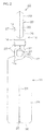
- plastic ampule 11 drug solution storage part, 12 drug solution discharge tube, 13 top part, 14 fragile part, 18 intermediate layer, 19 inner layer, 20 outer layer, 21 adhesive layer, 22 adhesive layer, 28 tab, 31 reinforcing member, 101 colored layer, 102 cyclic olefin polymer layer, 104 intermediate layer, 110 colored plastic ampule, 111 drug solution storage part, 112 drug solution discharge tube, 113 top part
- FIG. 1 is a front view of an embodiment of a plastic ampule according to the present invention.
- FIG. 2 is a left side view
- FIG. 3 is a plan view
- FIG. 4 is a bottom view
- FIG. 5 is a left side sectional view
- FIG. 6 is a sectional view taken along line A-A
- FIG. 7 is a sectional view taken along line B-B.
- a rear view appears the same as the front view
- a right side view appears the same as the left side view.
- the plastic ampule 10 includes a drug solution storage part 11 formed to a bottomed cylindrical shape and being for storing a drug solution, a drug solution discharge tube 12 in communication with an open end 11a of the drug solution storage part 11 and extending toward one side, and a top part 13 closing an end at the one side of the drug solution discharge tube 12, and the drug solution discharge tube 12 includes a fragile part 14 formed to have a thin thickness along a circumferential direction.
- the drug solution storage part 11 has the open end 11a formed at an end at the one side opposite a bottom part 16 in a longitudinal direction extending along a central axis 15 of the drug solution storage part 11, and has a shoulder part 17, which decreases in diameter from the bottom part 16 side toward the open end 11a side (toward the one side), in a vicinity of the open end 11a.
- a cross-sectional shape of the drug solution storage part 11 is formed to be circular in plan view or bottom view, the cross-sectional shape of the drug solution storage part 11 is not restricted thereto and may be formed, for example, to be elliptical. [0037Referring again to FIG. 1 and FIG.
- the drug solution discharge tube 12 is formed to continue from the open end 11a of the drug solution storage part 11 and extend along an axial direction of the central axis 15 of the drug solution storage part 11 with the same axis as the central axis 15 as its central axis.
- the top part 13 At the end at the one side of the drug solution discharge tube 12 (that is, the end of the drug solution discharge tube 12 at the side opposite the open end 11a side of the drug solution storage part 11a) is formed the top part 13 that continues from the end at the one side and seals the drug solution discharge tube 12.
- the drug solution discharge tube 12 preferably has an inner diameter that fits with a nozzle of a syringe for suctioning the drug solution inside the drug solution storage part 11 when the nozzle is inserted so that the nozzle is fixed in a stable state, and preferably has an adequate length in the axial direction of the drug solution discharge tube 12 between the drug solution storage part 11 and the top part 13.
- the drug solution storage part 11, the drug solution discharge tube 12, and the top part 13 are mutually continuous, integral, and form a closed region for storing and sealing the drug solution.
- the drug solution discharge tube 12 has the fragile part 14 formed to have the thin thickness along the circumferential direction of the drug solution discharge tube 12 at a substantially middle portion between the open end 11a of the drug solution storage part 11 and the end at the one side of the drug solution discharge tube 12 (see FIG. 5 ).
- the fragile part 14 can thereby be twisted off or cleaved and torn open readily by holding the drug solution storage part 11 and the top part 13 side of the drug solution discharge tube 12 and twisting or bending these parts with respect to each other.
- the plastic ampule 10 can thereby be opened.
- the drug solution discharge tube 12 is thereby opened and a nozzle of an unillustrated syringe can be inserted into an opening thus formed to collect the drug solution stored in the drug solution storage part 11.
- the syringe is used, for example, by inserting its nozzle, without an injection needle being attached to a tip of the nozzle, into the opening of the drug solution discharge tube 12 and sectioning the drug solution stored inside the drug solution storage part 11.
- the drug solution housing part 11, the drug solution discharge tube 12, and the top part 13 are formed of a multilayer plastic material that includes, for example, an intermediate layer 18 containing a cyclic olefin-based (co)polymer with a glass transition temperature of 60 to 80°C, an inner layer 19 laminated to an inner side of the plastic ampule 10 with respect to the intermediate layer 18, an outer layer 20 laminated to an outer side of the plastic ampule 10 , an adhesive layer 21 disposed between the intermediate layer 18 and the inner layer 19, and an adhesive layer 22 disposed between the intermediate layer 18 and the outer layer 20.
- an intermediate layer 18 containing a cyclic olefin-based (co)polymer with a glass transition temperature of 60 to 80°C an inner layer 19 laminated to an inner side of the plastic ampule 10 with respect to the intermediate layer 18, an outer layer 20 laminated to an outer side of the plastic ampule 10 , an adhesive layer 21 disposed between the intermediate layer 18 and the inner layer 19, and an adhesive layer 22 disposed between the intermediate layer
- the adhesive layer 21 disposed between the intermediate layer 18 and the inner layer 19 and the adhesive layer 22 disposed between the intermediate layer 18 and the outer layer 20 are both arbitrary layers , and the adhesive layers 21 and 22 may be omitted to dispose the inner layer 19 and the outer layer 20 directly on respective surfaces of an inner side surface and an outer side surface of the plastic ampule 10 with respect to the intermediate layer 18.
- cyclic olefin-based (co)polymer with the glass transition temperature of 60 to 80°C used to form the intermediate layer 18 a copolymer of ethylene and a dicyclopentadiene, a copolymer of ethylene and a norbornene-based compound, a ring-opened polymer of a cyclopentadiene derivative, a ring-opened copolymer of a plurality of cyclopentadiene derivatives, and a hydrogenate of any of the above can be cited.
- Such a cyclic olefin-based (co) polymer with the glass transition temperature of 60 to 80°C may be used solitarily or two or more types of the (co) polymer may be used upon mixing.
- a hydrogenate of a copolymer of ethylene and a norbornene-based compound and a hydrogenate of a ring-opened (co)polymer of one or more cyclopentadiene derivatives can be cited as preferable examples of the cyclic olefin-based (co)polymer.
- the plastic ampule can be improved further in strength and water permeation preventing ability, and moreover, the plastic ampule can be imparted with a gas permeation preventing ability.
- a copolymer having repeating units indicated by General Formula (A) and repeating units indicated by General Formula (A'), and a polymer having repeating units indicated by General Formula (B) can be cited.
- R 1 , R 1 , R 2 , R 2 , R 3 and R 4 are the same or different, with each indicating hydrogen, a hydrocarbon residual, or a polar group.
- R 1 and R 2 , R 1' and R 2' , and R 3 and R 4 may respectively be bonded mutually to form a ring.
- an alkyl group can be cited, an alkyl group with 1 to 6 carbons can be cited as a preferable example, and an alkyl group with 1 to 4 carbons can be cited as a more preferable example.
- a halogen atom for example, a fluorine atom, chlorine atom, bromine atom, iodine atom, etc.
- an ester for example, a nitrile, a pyridyl, etc.
- a polymer having the repeating units indicated by the General Formulae (A) and (A') is obtained by polymerizing one type or two or more types of monomer by a known ring-opening polymerization reaction or using a conventional method to hydrogenate a ring-opened polymer thus obtained.
- Such a polymer can be obtained, for example, as a product of the trade name "Zeonoa (registered trademark), " made by Zeon Corp., or a product of the trade name "ARTON (registered trademark),” made by JSR Corp.
- a polymer having the repeating units indicated by the General Formula (B) is obtained by performing either or both of an addition polymerization by a known method of one or two or more types of a norbornene-based monomer and ethylene as monomers and a hydrogenation by a conventional method of a product of the addition polymerization.
- Such a polymer can be obtained, for example, as a product of the trade name "APEL (registered trademark),” made by Mitsui Chemicals, Inc. , or a product of the trade name “Topas (registered trademark),” made by Ticona GmbH.
- the hydrogenates of the polymers having the repeating units indicated by the General Formulae (A) and (A') are saturated polymers in all cases and are thus excellent in gas blocking property and water blocking property as well as in heat resistance, transparency, and stability.
- the glass transition temperature (Tg) of the cyclic olefin co (polymer) is a midpoint glass transition temperature (T mg ) measured by input compensation differential scanning calorimetry (input compensation DSC) described in JIS K 7121 -1987 "Testing Methods for Transition Temperatures of Plastics, " and the Tg of the cyclic olefin-based (co) polymer used in forming the intermediate layer 18 is set in the range of 60 to 80°C as mentioned above and preferably in the range of 65 to 80°C.
- melt flow rate (MFR) of the cyclic olefin-based (co)polymer is not restricted in particular, it is preferably 4 to 30g/10 minutes (260°C) from standpoints of moldability, mechanical characteristics, etc., of the plastic ampule.
- MFR melt flow rate
- a molecular weight of the cyclic olefin-based (co)polymer is not restricted in particular, a number average molecular weight ⁇ Mn> is preferably 10,000 to 100,000 and more preferably 20,000 to 50,000. The average molecular weight is determined, for example, as a styrene equivalent value by gel permeation chromatography (GPC) analysis using cyclohexane as a solvent.
- the intermediate layer 18 may be formed solely of the cyclic olefin-based (co)polymer with the glass transition temperature (Tg) of 60 to 80°C, it may also be formed of a mixed resin including the cyclic olefin-based (co) polymer with the glass transition temperature of 60 to 80°C and polyethylene.
- a mixed resin including the cyclic olefin-based (co)polymer with the glass transition temperature of 60 to 80°C and a high-pressure polyethylene with a density of 0.900 to 0.940g/cm 3 (more preferably, a density of 0.920 to 0.930g/cm 3 ) or a high-density polyethylene with a density of 0.940 to 0.970g/cm 3 can be cited.
- the high-pressure polyethylene is a branched-chain polyethylene manufactured by a high pressure method.
- the high-density polyethylene is a straight-chain polyethylene manufactured by a medium or low pressure method
- the high-density polyethylene may, for example, be a homopolymer of ethylene or may be a copolymer of ethylene and an ⁇ -olefin such as propene, butene-1, pentene-1, hexene-1,4-methylpentene-1, octene-1, decene-1, etc.
- the force required to tear open the fragile part 14 by twisting off or cleaving can be set readily, and an adhesive property of the intermediate layer 18 with the inner layer 19 and the outer layer 20 that are adjacent the intermediate layer 18 is improved. Further, mixing of the high-density polyethylene with the cyclic olefin-based (co) polymer is favorable in that the transparency of the mixed resin can be maintained adequately.
- the content proportion of the high-pressure polyethylene with the density of 0.900 to 0.940g/cm 3 (more preferably, a density of 0.920 to 0.930g/cm 3 ) or the high-density polyethylene with the density of 0.940 to 0.970g/cm 3 is preferably no more than 30 weight %, more preferably 5 to 30 weight %, and especially preferably 5 to 25 weight % of the entire mixed resin.
- the mixing proportion of the high-pressure polyethylene or the high-density polyethylene in the mixed resin exceeds the above range, the above-described performance required of the cyclic olefin-based (co)polymer may not be adequate.
- a polyolefin can be cited as an example of the resin forming the inner layer 19 and the outer layer 20.
- the polyolefin is not restricted in particular and various polyolefin that are conventionally used in medical plastic containers can be cited as examples and among these, polyethylene-based resins and polypropylene-based resins can be cited as preferable examples.
- a polypropylene-based resin is favorably used in a case where heat resistance of the medical plastic container is stressed.
- polyethylene-based resins examples include homopolymers, such as a high-pressure (branched) low-density polyethylene (HP-LDPE), straight-chain low-density polyethylene (LLDPE), medium-density polyethylene (MDPE), high-densitypolyethylene (HDPE), etc., and polyethylene-based copolymers can be cited.
- HP-LDPE high-pressure low-density polyethylene
- LLDPE straight-chain low-density polyethylene
- MDPE medium-density polyethylene
- HDPE high-densitypolyethylene
- polyethylene-based copolymers examples include polyethylene-based copolymers.
- the content proportion of the comonomer besides ethylene is preferably no more than 20 mole % and more preferably 3 to 20 mole %.
- a polyethylene-based resin of comparatively low density specifically, a high-pressure polyethylene with a density in a range of 0.900 to 0.940g/cm 3 and more preferably 0.920 to 0.930g/cm 3 is favorably selected.
- the high-pressure polyethylene the same resin as that cited for forming the intermediate layer 18 can be cited.
- melt flow rate (MFR) of the polyethylene-based resin is not restricted in particular, it is preferably 0.2 to 20g/10 minutes (190°C) from standpoints of the moldability with the intermediate layer 18 that contains the cyclic olefin-based (co)polymer, mechanical characteristics of the plastic ampule, etc.
- the polypropylene-based resin crystalline homopolymers, such as isotactic polypropylene, syndiotactic polypropylene, etc., and crystalline copolymers containing a small amount of a commoner can be cited.
- ⁇ -olefins such as ethylene, butene-1, pentene-1, hexene-1,4-methylpentene-1, octene-1, decene-1, etc.
- the content proportion of the comonomer besides propylene in the crystalline copolymer is preferably no more than 30 mole %, more preferably 2 to 30 mole%, and especially preferably 3 to 25 mole %.
- thermoplastic elastomer is used favorably for the purpose of imparting flexibility to the polypropylene-based resin.
- a polypropylene elastomer manufactured using a metallocene catalyst and having a density of 0.860 to 0.870g/cm 3 and a glass transition temperature (Tg) of no more than-10°C has all of heat resistance, transparency, and flexibility and is thus favorable for the present invention.
- Tg glass transition temperature
- a product of the trade name "NOTIO,” made by Mitsui Chemicals, Inc. is available as such a polypropylene elastomer.
- low-crystallinity polypropylene copolymers for example, a product of the trade name "Toughmer (registered trademark)" X Series, etc., made by Mitsui Chemicals, Inc.
- a compounding proportion of such a polypropylene elastomer is preferably 10 to 40 weight % with respect to the total amount of the resin forming the inner layer 19 or the outer layer 20.
- melt flow rate (MFR) of the polypropylene-based resin is not restricted in particular, it is preferably 0.2 to 20g/10 minutes (230°C) from standpoints of the moldability with the intermediate layer 18 that contains the cyclic olefin-based (co)polymer, mechanical characteristics of the plastic ampule, etc.
- the inner layer 19 and the outer layer 20 may be formed, for example, from just the polyethylene-based resin or the polypropylene-based resin, these may also be formed, for example, from a mixture of polypropylene, a polypropylene elastomer, and a nucleating agent. In this case, the transparency of the inner layer 19 and the outer layer 20 can be improved.
- phosphate-based nucleating agents such as sodium 2,2'-nethylene-bis-(4,6-di-t-butylphenyl)phosphate (NA-11), hydroxyaluminum-bis [2,2'-methylene-bis-(4,6-di-t-butylphenyl) phosphate] (NA-21), etc., can be cited.
- Each of the inner layer 19 and the outer layer 20 is not restricted to being a single layer and may, for example, be a laminate of layers formed of mutually different resins selected from among the above mentioned resins.
- the adhesive layers 21 and 22 may respectively be disposed as a layer between the intermediate layer 28 and the inner layer 19 and a layer between the intermediate layer 18 and the outer layer 20.
- the resin forming the adhesive layers 21 and 22 LLDPE (in particular, LLDPE polymerized using a metallocene catalyst or other single-site catalyst), a polyethylene-based elastomer, and a mixed resin of the above can be cited.
- an unsaturated carboxylic acid-modified polyethylene an ethylene-acrylic acid copolymer, an ethylene-vinyl acetate copolymer, etc., which are known as adhesive resins, can be cited.
- each of the adhesive layers 21 and 22 is not restricted in particular and suffices to be a thickness adequate for adhesion of the adjacent layers (the intermediate layer 18 and the inner layer 19 or the intermediate layer 18 and the outer layer 20). Specifically, the thickness is preferably approximately 2 to 10% of the thickness of an adjacent layer.
- a colorant, an ultraviolet absorber, etc. may be compounded in the outer layer 20.
- the colorant is a component that is compounded for a purpose of lowering light transmittance of the plastic ampule to prevent photodegradation of the drug solution stored in the plastic ampule or a purpose of imparting design quality to the plastic ampule, and as specific examples, a yellow pigment, such as C. I. pigment yellow 95, C. I.
- pigment yellow 147 C. I. pigment yellow 180, C. I. pigment yellow 181, etc.
- a red pigment such as C. I. pigment red 220, C. I. pigment red 177, etc.
- a blue pigment such as C. I. pigment blue 60, etc.
- Such a pigment may be used solitarily or two or more types may be used upon mixing.
- a compounding amount of the colorant may be set as suited according to the thickness of the resin forming the outer layer 20, a degree of light blocking property required of the plastic ampule, etc., and is not restricted in particular, and for example, is preferably 0,01 to 0.4 weight % in the resin forming the outer layer 20.
- the ultraviolet absorber is a component that is compounded for a purpose of lowering an ultraviolet transmittance of the plastic ampule to prevent degradation of the drug solution contained in the plastic ampule by ultraviolet rays
- benzotriazole-based ultraviolet absorbers such as 2-(2'-hydroxy-5'-methylphenol)benzotriazole (product of the trade name "Tinuvin (registered trademark) P," made by Ciba Specialty Chemicals Inc.), 2-(2'-hydroxy-3',5'-bis(methylbenzyl)phenol)benzotriazole (product of the trade name "Tinuvin (registered trademark) 234, " made by the same company), 2-(2'-hydroxy-3'-tert-butyl-5'-methylphenol)-5-chlorobenzo triazole (product of the trade name "Tinuvin (registered trademark) 326," made by the same company), 2-(2'-hydroxy-3',5'-di-tert-butylphenol)-5-chloro
- the compounding amount of the ultraviolet absorber may be set as suited according to the thickness of the resin forming the outer layer 20, a degree of ultraviolet blocking property required of the plastic ampule, etc., and is not restricted in particular, and for example, is preferably 0.01 to 0.4 weight % in the resin forming the outer layer 20.
- an ultraviolet absorber is compounded in the resin forming the outer layer 20, it is preferable to further compound metal oxide microparticles from standpoints of improving an efficiency of ultraviolet absorption by the ultraviolet absorber and reducing a usage amount of the ultraviolet absorber.
- titanium oxide, zinc oxide, iron oxide, cerium oxide, magnesium oxide, etc. can be cited.
- an average particle diameter of the metal oxide microparticles is not restricted in particular, it is preferably no more than 50nm and more preferably no more than 30nm from a standpoint of maintaining the transparency of the plastic ampule.
- the compounding amount of the metal oxide microparticles may be set as suited according to the type and compounding amount of the ultraviolet absorber used, the thickness of the resin forming the outer layer 20, the transparency and the degree of ultraviolet blocking property required of the plastic ampule, etc., and is not restricted in particular, and for example, is preferably 0.01 to 0.4 weight % in the resin forming the outer layer 20.
- the combination of the ultraviolet absorber and the metal oxide microparticles is not restricted in particular, a combination of 2-(2'-hydroxy-3'-tert-butyl-5'-methylphenol)-5-chlorobenzo triazole (the abovementioned product of the trade name "Tinuvin (registered trademark) 326”) and zinc oxide microparticles can be cited as a preferable example.
- the thickness is set within a range of 10 to 50% of the entirety of the layers formed from the multilayer plastic material, and the proportions of the thicknesses of the respective layers may be set as suited according to the type and storage amount of the drug solution stored in the plastic ampule, etc.
- the thickness of the multilayer plastic material may be set as suited according to usage of the plastic ampule 10, the type and storage amount of the drug solution stored in the plastic ampule 10, etc., and is not restricted in particular and, for example, is preferably 300 to 1500 ⁇ m and more preferably 400 to 1200 ⁇ m at the drug solution storage part 11.
- the thickness of the multilayer plastic material may be the same or may differ respectively at the drug solution storage part 11, the drug solution discharge tube 12, and the top part 13.
- the force required to tear open (twist open or cleave) the fragile part 14, that is, the torque required to tear open the entire fragile part 14 is preferably set to no more than 0.40N ⁇ m and more preferably to 0.05 to 0.40N ⁇ m from a standpoint of operability in the process of opening the plastic ampule 10. Also, the force required to tear open the fragile part 14 is preferably no more than 0.65N ⁇ m/mm and more preferably 0.05 to 0.65N ⁇ m/mm with respect to the thickness of the multilayer plastic material at the drug solution discharge tube 12.
- the fragile part 14 By the force required to tear open the fragile part 14 (the force per unit length of thickness of the multilayer plastic material) being set within the above range at a portion of the drug solution discharge tube 12, which is adjacent to the fragile part 14 and at which the thickness of the multilayer plastic material is substantially uniform, the fragile part 14 can be torn open with good operability.
- the force required to tear open the fragile part 14 may be adjusted as suited by the types of resins of the respective layers forming the multilayer plastic material.
- the thickness of the intermediate layer made of the cyclic olefin (co) polymer is preferably set to 25 to 45% and more preferably to 30 to 40% of the thickness of the multilayer plastic material as a whole.
- the drug solution storage part 11 has, on an outer peripheral surface 23 thereof, a rib 24 extending along an axial direction of the central axis 15 and protruding outward in radial directions from the outer peripheral surface 23 of the drug solution storage part 11 at positions opposing each other across the central axis 15 of the drug solution storage part 11. Also, the drug solution storage part 11 has, on the bottom part 16 thereof, a rib 25 protruding outward from the bottom part 16, and the rib 24 on the outer peripheral surface 23 and the rib 25 on the bottom part 16 are mutually continuous.
- the two ribs 24 and 25 that are mutually continuous are formed due to a manufacturing method of the plastic ampule 10 to be described below.
- the drug solution storage part 11 is imparted with rigidity and shape maintenance of the drug solution storage part 11 is achieved.
- a tab 28 that protrudes to an outer side of the drug solution discharge tube 12 in continuation from a portion of the drug solution discharge tube 12 at a top part 13 side relative to the fragile part 14 and protrudes to an outer side of the top part 13 in continuation from an outer surface 27 of the top part 13.
- the drug solution storage part 11 and the drug solution discharge tube 12 are made unlikely to deform when the drug solution storage part 11 and the top part 13 side of the drug solution discharge tube 12 are held and twisted or bent with respect to each other. Also, the operation of opening the plastic ampule 10 by twisting off or cleaving the fragile part 14 of the drug solution discharge tube 12 can thereby be performed easily and yet reliably.
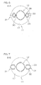
- the tab 28 includes a flat part 29 and a chamfered part 30 formed at a periphery of the flat part 29, and an interior of the tab 28 forms a hollow, thick portion (see FIG. 6 ).
- the rigidity of the tab 28 itself is thereby maintained, and deformation of the tab 28 when the tab 28 is held to open the plastic ampule 10 can be suppressed.
- reinforcing members 31 that respectively protrude to outer sides of the drug solution discharge tube 12 and the drug solution storage part 11 and are mutually connected are provided at the outer peripheral surface 23 of the drug solution storage part 11 at the shoulder part 17 and the outer peripheral surface 26 of the drug solution discharge tube 12 at the drug solution storage part 11 side relative to the fragile part 14.
- the reinforcing members 31 being formed continuously so as to span across the portion of the drug solution discharge tube 12 at the drug solution storage part 11 side relative to the fragile part 14 and the shoulder part 17 of the drug solution storage part 11, the rigidity between the drug solution storage part 11 and the drug solution discharge tube 12 is improved significantly.
- the drug solution discharge tube 12 that protrudes from the drug solution storage part 11 is thereby made unlikely to break, for example, during transport and handling of the plastic ampule 10.
- each reinforcing member 31 includes a flat part 32 and a chamfered part 33 formed at a periphery of the flat part 32, and an interior of the tab 28 forms a hollow, thick portion (see FIG. 7 ) .
- the rigidity of each reinforcing member 31 itself is there by maintained to further improve the reinforcing effect, and the deformation of the reinforcing members 31 can be suppressed when the reinforcing members 31 are held to open the plastic ampule 10.
- good contact with the reinforcing members 31 can be made with the fingers when the tab 28 is twisted.
- the reinforcing members 31 are preferably formed along the same plane as the tab 28 as shown in FIG. 2 . In this case, a slim outer appearance is obtained, the plastic ampule 10 is thereby made easy to store, and fingers can be set readily on the reinforcing members 31 when twisting the tab 28.
- the reinforcing members 31 may instead be formed in directions orthogonal to the tab 28.
- the tab 28 and the reinforcing members 31 can be molded along with the respective parts of the drug solution storage part 11, the drug solution discharge tube 12, and the top part 13 during manufacture of the plastic ampule 10.
- the plastic ampule 10 can be manufactured, for example, by a molding method that combines a so-called blow-fill-seal method, described for example in Patent Document 2, and a multilayer blow molding method. Specifically, first, the multilayer plastic material is extrusion molded to prepare a parison with a multilayer structure in which the inner layer 19, the adhesive layer 21, the intermediate layer 18, the adhesive layer 22, and the outer layer 20 are mutually fused and laminated in that order from the inner side.
- the multilayer parison thus obtained is then sandwiched in a split mold and the respective parts of the drug solution storage part 11, the drug solution discharge tube 12, and the reinforcing members 31 are formed (blowing step), the interior of the drug solution storage part 11 is filled with the drug solution (filling step), and the top part 13 and the tab 28 are formed by further sandwiching with a split mold to form a closed region made up of the drug solution storage part 11, the drug solution discharge tube 12, and the top part 13 (sealing step) and thereby obtain the sealed plastic ampule 10 filled with the drug solution.
- the two ribs 24 and 25 are formed along mating surfaces of the split mold when the parison is sandwiched by the split mold.
- the parison with the multilayer structure can be prepared according to a conventional method for multilayer blow molding.
- the extruder, die shape, molding conditions of the parison with the multilayer structure, etc. are not restricted in particular, and these may be set as suited in accordance with the conventional method for multilayer blow molding.
- the manufacture of the plastic ampule by the blow-fill-seal method using the parison with the multilayer structure can be carried out in the same manner as in manufacture of a plastic ampule by the BFS method using a parison with a single layer structure with the exception of the difference in the layer structure of the parison (differences in the number of extruders and the structures of the dies for forming the parison) .
- the respective layers of the multilayer film may be mutually fused and laminated as mentioned above or may be mutually adhered by interposing layers made of the adhesive resin between the respective layers.
- the plastic ampule according to the present invention can be used widely, for example, in medical applications.
- a preferred embodiment of a colored plastic container according to the present invention shall now be described in detail with reference to the attached drawings.
- the colored plastic container according to the present invention is formed of a thermoplastic multilayer plastic material that includes a colored layer containing a pigment and an ultraviolet absorber, and an inner layer laminated directly or across an intermediate layer onto one side surface of the colored layer.
- FIG. 8 is a sectional view of an example of a layer arrangement of a thermoplastic multilayer plastic material that forms a colored plastic container
- FIG. 9 and FIG. 10 are respectively sectional views of other examples of a layer arrangement of a thermoplastic multilayer plastic material.
- portions that are the same or are of the same type shall be provided with the same symbol throughout the plurality of layer arrangement examples.
- the thermoplastic multilayer plastic material includes a colored layer 101 containing a pigment and an ultraviolet absorber, a cyclic olefin polymer layer 102 laminated onto one side surface of the colored layer 101, and a polyolefin layer 103 laminated onto a surface of the cyclic olefin polymer layer 102 at the opposite side of the colored layer 101.
- the colored layer 101 is a layer forming an outer layer of the colored plastic container
- the cyclic olefin polymer layer 102 is a layer forming an intermediate layer of the colored plastic container
- the polyolefin layer 103 is a layer forming an inner layer of the colored plastic container.
- the cyclic olefin polymer layer 102 is a layer disposed to prevent the pigment and the ultraviolet absorber contained in the color layer from transferring into a content stored in the colored plastic container and is an arbitrary layer in the thermoplastic multilayer plastic material forming the colored plastic container according to the present invention.
- the thermoplastic multilayer plastic material shown in FIG. 9 includes the colored layer 101 containing the pigment and the ultraviolet absorber, an intermediate layer 104 with a three-layer structure laminated onto one side surface of the colored layer 101, and the polyolefin layer 103 laminated onto a surface of the intermediate layer 104 at the opposite side of the colored layer 101.
- the intermediate layer 104 includes the cyclic olefin polymer layer 102 and a total of two polyolefin layers 105 and 106 respectively laminated by one layer each onto one side surface and the other side surface of the cyclic olefin polymer layer 102.
- the colored layer 101 is the layer forming the outer layer of the colored plastic container
- the polyolefin layer 103 is the layer forming the inner layer of the colored plastic container.
- the thermoplastic multilayer plastic material shown in FIG. 10 includes the polyolefin layer 103, the colored layer 101 containing the pigment and the ultraviolet absorber and laminated onto one side surface of the polyolefin layer 103, and the cyclic olefin polymer layer 102 laminated onto the surface of the colored layer 101 at the opposite side of the polyolefin layer 103.
- the polyolefin layer 103 is the layer forming the outer layer of the colored plastic container
- the cyclic olefin polymer layer 102 is the layer forming the inner layer of the colored plastic container.
- the colored layer 101 is the layer forming the intermediate layer of the colored plastic container.
- Each of the thermoplastic multilayer plastic materials shown in FIG. 8 to FIG. 10 may have adhesive layers disposed between the respective layers.
- the layer arrangement of the thermoplastic multilayer plastic material is not restricted in particular, for example, the colored layer 101 is preferably disposed as much as possible at the outer side of the colored plastic container to efficiently impart the colored plastic container with a light blocking property. This measure is especially effective in a case where the colored plastic container is an ampule or other comparatively small container.
- the plastic material forming the colored layer is not restricted in particular besides being a plastic material with thermoplasticity, and a polyolefin can be cited as a specific example.
- polyethylene-based resins and polypropylene-based resins can be cited as preferable examples .
- a polypropylene-based resin is favorably used in a case where heat resistance is required of the colored plastic container.
- polyethylene-based resins homopolymers, such as a high-pressure (branched) low-density polyethylene (HP-LDPE), straight-chain low-density polyethylene (LLDPE), medium-density polyethylene (MDPE) , high-density polyethylene (HDPE), etc.
- polyethylene-based copolymers can be cited.
- ⁇ -olefins such as propylene, butene-1, pentene-1, hexene-1,4-methylpentene-1, octene-1, decene-1, etc.
- the content proportion of the comonomer besides ethylene is preferably no more than 20 mole % and more preferably 3 to 20 mole %.
- the density is preferably in a range of 0.910 to 0.930g/cm 3
- the melt flow rate (MFR) is preferably 0.2 to 20g/10 minutes (190°C).
- polypropylene-based resin homopolymers, such as isotactic polypropylene, syndiotactic polypropylene, etc., and polypropylene-based copolymers can be cited.
- comonomer besides propylene in the polypropylene-based copolymer ⁇ -olefins such as ethylene, butene-1, pentene-1, hexene-1,4-methylpentene-1, octene-1, decene-1, etc.
- the content proportion of the comonomer besides propylene in the copolymer is preferably no more than 30 mole %, more preferably 2 to 30 mole %, and even more preferably 3 to 25 mole %.
- the MFR is preferably 0.2 to 20g/10 minutes (230°C).
- a polypropylene-based resin with the MFR within the above range is favorable for improving the mechanical characteristics of the colored plastic container and is especially favorable in a case where the cyclic olefin polymer layer is disposed between the colored layer and the inner layer.
- the colored layer may be formed, for example, from a mixture of polypropylene, a polypropylene elastomer, and a nucleating agent. In this case, the transparency of the colored layer can be improved.
- phosphate-based nucleating agents such as sodium 2,2'-methylene-bis-(4,6-di-t-butylphenyl)phosphate (NA-11), hydroxyaluminum-bis[2,2'-methylene-bis-(4,6-di-t-butylphen yl)phosphate] (NA-21), etc.
- the pigment is a component that is compounded for a purpose of lowering the light transmittance of the colored plastic container to prevent alteration due to light rays (especially ultraviolet rays) of the contents (for example, a drug solution, etc.) stored in the colored plastic container.
- the pigment may be compounded for the purpose of imparting design quality to the colored plastic container.
- the pigment contained in the colored layer is selected as suited according to the type of the contents contained in the colored plastic container, that is, according to a wavelength range of the light rays to be blocked to improve the preservation property of the contents.
- organic pigments including azo condensation pigments (such as C. I. pigment yellow 95 indicated by the formula below, C. I. pigment yellow 93 indicated by the formula below, C. I. pigment yellow 94 indicated by the formula below, C. I. pigment yellow 128 indicated by the formula below, C. I. pigment red 144, C. I. pigment red 220, C. I. pigment red 221, C. I.
- pigment red 242, etc. isoindoline pigments (such as C. I. pigment yellow 110 indicated by the formula below, C. I. pigment yellow 109, C. I. pigment yellow 139, C. I. pigment yellow 173, C. I. pigment orange 61, C. I. pigment orange 68, etc.), monoazo pigments (such as C. I. pigment yellow 181, etc.), disazo pigments (such as C. I. pigment yellow 180, etc.), anthraquinone-based pigments (such as C. I. pigment yellow 147, etc.), dioxazine-based pigments, quinacridone-based pigments, etc., and inorganic pigments, including iron oxide, C. I. pigment blue 28 (cobalt blue; cobalt aluminate), C. I. pigment yellow 53 (titanium yellow; nickel yellow), etc., can be cited as examples of the pigment.
- isoindoline pigments such as C. I. pigment yellow 110 indicated by the formula below, C. I.
- an azo condensation yellow pigment is favorable as the pigment from a standpoint of blocking light rays of the ultraviolet region efficiently.
- an azo condensation yellow pigment is favorable as the pigment from a standpoint of improving the effect of suppressing the alteration of sodium ozogrel, and C. I. pigment yellow 95 is especially favorable.
- the ultraviolet absorber is a component that is compounded for a purpose of lowering an ultraviolet transmittance of the colored plastic container to prevent alteration of the contents (for example, a. drug solution, such as an aqueous solution of sodium ozagrel, etc.) contained in the colored plastic container by ultraviolet rays.
- a. drug solution such as an aqueous solution of sodium ozagrel, etc.
- ultraviolet absorbers that are benzophenone-based, benzotriazole-based, triazine-based, anilide oxalate-based, cyanoacrylate-based, etc. , can be cited.
- Benzotriazole-based ultraviolet absorbers are especially favorable.
- benzotriazole-based ultraviolet absorbers such benzotriazole-based ultraviolet absorbers as 2-(2'-hydroxy-3'-tert-butyl-5'-methylphenol)-5-chlorobenzo triazole (product of the trade name "Tinuvin (registered trademark) 326," made by Ciba Specialty Chemicals Inc.), 2- (2'-hydroxy-5'-methylphenol) benzotriazole (product of the trade name "Tinuvin (registered trademark) P, " made by the same company), 2-(2'-hydroxy-3',5'-bis(methylbenzyl)phenol)benzotriazole (product of the trade name "Tinuvin (registered trademark) 234," made by the same company), 2-(2'-hydroxy-3',5'-di-tert-butylphenol)-5-chlorobenzotriazole (product of the trade name "Tinuvin (registered trademark) 327,” made by the same company), 2-(2'-hydroxy-3' ,5'-methylphenol
- the drug solution stored in the colored plastic container is sodium ozagrel (specifically, an aqueous solution thereof or the solitary substance, etc.)
- a benzotriazole-based ultraviolet absorber is favorable, and the product of the trade name "Tinuvin (registered trademark) 326" is especially favorable.
- the colored layer may further have various additives besides the pigment and the ultraviolet absorber compounded therein as necessary.
- metal oxide microparticles may furthermore be contained along with the ultraviolet absorber.
- the metal oxide of the metal oxide microparticles titanium oxide, zinc oxide, iron oxide, cerium oxide, magnesium oxide, etc.
- the combination of the ultraviolet absorber and the metal oxide microparticles is not restricted in particular, a combination of the product of the trade name "Tinuvin (registered trademark) 326" and zinc oxide microparticles can be cited as a preferable example.
- the inner layer is a layer formed of a plastic material with thermoplasticity, and a polyolefin layer, a cyclic olefin polymer layer, etc., can be cited as specific examples as mentioned above.
- a polyolefin forming the polyolefin layer the same types as those of the plastic material forming the colored layer can be cited.
- the cyclic olefin-based polymer forming the cyclic olefin polymer layer a copolymer of a cyclic olefin and an olefin, a ring-opened polymer of a cyclic olefin, and a hydrogenate of any of the above can be cited.
- a copolymer of ethylene and a dicyclopentadiene a copolymer of ethylene and a norbornene-based compound, a ring-opened polymer of a cyclopentadiene derivative, a ring-opened copolymer of two or more types of cyclopentadiene derivatives, and a hydrogenate of any of the above can be cited.
- a hydrogenate of a copolymer of ethylene and a norbornene-based compound and a hydrogenate of a ring-opened (co) polymer of one type or two or more types of cyclopentadiene derivatives can be cited as preferable examples.
- the glass transition temperature (Tg) of the cyclic olefin-based polymer is not restricted in particular, it is preferably 60 to 80°C and more preferably 65 to 80°C as the midpoint glass transitiontemperature (T mg ) measured by input compensation differential scanning calorimetry (input compensation DSC) described in JIS K 7121- 1937 "Testing Methods for Transition Temperatures of Plastics.”
- Tg of the cyclic olefin-based polymer exceeds 80°C, for example, in a case where the colored plastic container is an ampule to be described below, problems, such as remaining of fine pieces of resin, called “whiskers,” on an opening formed by tearing open the ampule and the force required for tearing open being too large, occur.
- the Tg of the cyclic olefin copolymer falls below 60°C, the effect of preventing the transfer of the pigment and ultraviolet absorber in the colored layer and the gas and water vapor permeation preventing abilities may degrade.
- melt flow rate (MFR) of the cyclicolefin polymer is not restricted in particular, it is preferably 4 to 30g/10 minutes (260°C) from standpoints of moldability, mechanical characteristics, etc., of the colored plastic container.
- MFR melt flow rate
- the molecular weight of the cyclic olefin-based polymer is not restricted in particular, the number average molecular weight ⁇ Mn> is preferably 10, 000 to 100, 000 and more preferably 20, 00 to 50,000.
- the average molecular weight is determined, for example, as a standard polystyrene equivalent value by gel permeation chromatography (GPC) analysis using cyclohexane as a solvent.
- the intermediate layer is a layer made of a plastic material with thermoplasticity. Specific examples of the intermediate layer include the following:
- the same examples as those given above can be cited. Also, even in a case where the cyclic olefin polymer layer is to be made the intermediate layer as in (a) and (b), above, the same actions and effects as those in the case of making the cyclic olefin polymer layer the inner layer are obtained. That is, the effect of preventing the pigment and the ultraviolet absorber in the colored layer from transferring into the interior of the colored plastic container, the effect of improving the strength of the colored plastic container, and the effect of improving the water and gas permeation preventing abilities are obtained.
- polyethylene may be compounded suitably for the purpose of improving the adhesion property between layers and lessening a hardness of the colored plastic container.
- the polyethylene to be compounded in the cyclic olefin polymer layer formed as the intermediate layer that of a comparatively high density is preferable from a standpoint of maintaining the transparency of the thermoplastic multilayer plastic material.
- a polyethylene with a density of 0.935 to 0.970g/cm 3 is favorable.
- the content proportion of the polyethylene is preferably 5 to 20 weight parts with respect to a total of 100 weight parts of the cyclic olefin polymer layer.
- thermoplastic multilayer plastic material forming the colored layer and the pigment, ultraviolet absorber, and other additives contained in the colored layer in a case where the colored layer is the layer forming the intermediate layer of the coloured plastic container
- a layer such as an adhesive layer, a gas barrier layer, an oxygen absorbing layer, a sealant layer, etc., may be laminated as necessary onto the thermoplastic multilayer plastic material.
- a layer formed of an adhesive resin such as an unsaturated carboxylic acid-modified polyethylene, an ethylene-acrylic acid copolymer, an ethylene-vinyl acetate copolymer, etc.
- an adhesive resin such as an unsaturated carboxylic acid-modified polyethylene, an ethylene-acrylic acid copolymer, an ethylene-vinyl acetate copolymer, etc.
- a layer formed of a low-density polyethylene in particular, a polyethylene polymerized using a metallocene catalyst or other single-site catalyst and having a density of 0.890 to 0.920g/cm 3 can be cited.
- a thickness T of the colored layer is set to 50 to 1000 ⁇ m.
- the thickness T of the colored layer falls below 50 ⁇ m, it becomes difficult to compound the pigment and the ultraviolet absorber in the colored layer at amounts adequate to exhibit the actions and effects of the present invention.
- the thickness of the thermoplastic multilayer plastic material becomes too large as a whole and the moldability and handling properties of the colored plastic container degrade.
- the thickness T of the colored layer is preferably 50 to 400 ⁇ m and more preferably 50 to 300 ⁇ m.
- a product PT of a content proportion P (weight %) of the pigment in the colored layer and the thickness T ( ⁇ m) of the colored layer is set to satisfy Formula (1) below:
- the value of the product PT is preferably 5 to 120 and more preferably 5 to 60.
- the compounding amount of the colorant in the colored layer is not restricted in particular besides being set to satisfy the range of Formula (1) in relationship with the thickness T of the colored layer, it is preferable from the standpoint of dispersibility in the colored layer, etc., that the content proportion in the colored layer be, for example, 0.01 to 0.4 weight %.
- the product UT of the content proportion U (weight %) of the ultraviolet absorber in the colored layer and the thickness T ( ⁇ m) of the colored layer is set to satisfy Formula (2) below when the product PT of the content proportion P (weight %) of the pigment in the colored layer and the thickness T ( ⁇ m) of the colored layer exceeds 20 and to satisfy Formula (3) below when the product PT is no more than 20. 5 ⁇ UT ⁇ 160 20 ⁇ UT ⁇ 160
- Formula (1) By setting the value of the product PT to be within the range of Formula (1) while setting the value of the product UT to be within the range of Formula (2) or Formula (3), wavelengths of the ultraviolet region can be blocked efficiently while maintaining appropriate visibility of the interior of the container.
- the value of the product UT falls below the range of Formula (2) when the product PT exceeds 20 or falls below the range of Formula (3) when the product PT is no more than 20, the effect of blocking wavelengths of the ultraviolet region becomes inadequate.
- the value of UT exceeds the above range, the dispersibility of the ultraviolet absorber in the colored layer may degrade.
- the value of the product UT in the case where the product PT exceeds 20 is preferably 5 to 120 and more preferably 10 to 100.
- the value of the product UT in the case where the product PT is no more than 20 is preferably 30 to 160 and more preferably 35 to 160.
- the compounding amount of the ultraviolet absorber in the colored layer is not restricted in particular besides being set to satisfy the range of Formula (2) in relationship with the thickness T of the colored layer, it is preferable from the standpoint of dispersibility in the colored layer, etc., that the content proportion in the colored layer be, for example, 0.01 to 0.4 weight %.
- a quotient U/T of the content proportion U (weight %) of the ultraviolet absorber in the colored layer divided by the thickness T ( ⁇ m) of the colored layer preferably satisfies Formula (4) below.
- the ultraviolet absorber may exude (bleed) from the colored layer to an exterior of the colored plastic container.
- the value of the quotient U/T is preferably no more than 0.0038 and more preferably 0.0001 to 0.0038.
- the thicknesses of the respective layers besides the colored layer are each set in a range of 10 to 50% with respect to the entirety of the layers formed of the thermoplastic multilayer plastic material.
- the proportions of the thicknesses of the respective layers can be set as suited according to the type and storage amount of the contents stored in the multilayer plastic container, etc.
- the thickness of the thermoplastic multilayer plastic material as whole is set as suited according to the usage of the multilayer plastic container, the type and storage amount of the stored contents, etc., and although it is not restricted in particular, for example, it is preferably 300 to 1500 ⁇ m and more preferably 400 to 1200 ⁇ m.
- the drug contained in the colored plastic container according to the present invention is not restricted in particular and an aqueous solution of sodium ozagrel can be cited as a preferable example.
- FIG. 11 is a front view of an example of a colored plastic ampule as an embodiment of the colored plastic container
- FIG. 12 is a side view thereof
- FIG. 13 is a plan view thereof
- FIG. 14 is a bottom view thereof
- FIG. 15 is a side sectional view thereof.
- the colored plastic ampule 110 includes a drug solution storage part 111 formed to a bottomed cylindrical shape and being for storing a drug solution, a drug solution discharge tube 112 in communication with an open end 111a of the drug solution storage part 111 and extending toward one side, and a top part 113 closing an end at the one side of the drug solution discharge tube 112, and the drug solution discharge tube 112 includes a fragile part 114 that is formed to have a thin thickness along a circumferential direction.
- the drug solution storage part 111 has the open end 111a formed at an end at the one side opposite a bottom part 116 in a longitudinal direction extending along a central axis 115 of the drug solution storage part 111, and has a shoulder part 117, which decreases in diameter from the bottom part 116 side toward the open end 111a side (toward the one side), in a vicinity of the open end 111a.
- a cross-sectional shape of the drug solution storage part 111 is formed to be circular in plan view or bottom view, the cross-sectional shape of the drug solution storage part 111 is not restricted thereto and may be formed, for example, to be elliptical.
- the drug solution discharge tube 112 is formed to continue from the open end 111a of the drug solution storage part 111 and extend along an axial direction of the central axis 115 of the drug solution storage part 111 with the same axis as the central axis 115 as its central axis.
- the top part 113 that continues from the end at the one side and seals the drug solution discharge tube 112.
- the drug solution discharge tube 12 preferably has an inner diameter that fits with a nozzle of a syringe for suctioning the drug solution inside the drug solution storage part 111 when the nozzle is inserted so that the nozzle is fixed in a stable state, and preferably has an adequate length in the axial direction of the drug solution discharge tube 112 between the drug solution storage part 111 and the top part 113.
- the drug solution storage part 111, the drug solution discharge tube 112, and the top part 113 are mutually continuous, integral, and form a closed region for storing and sealing the drug solution.
- the drug solution discharge tube 112 has the fragile part 114 formed to have the thin thickness along the circumferential direction of the drug solution discharge tube 112 at a substantially middle portion between the open end 111a of the drug solution storage part 111 and the end at the one side of the drug solution discharge tube 112 (see FIG. 15 ).
- the fragile part 114 can thereby be twisted off or cleaved and torn open readily by holding the drug solution storage part 111 and the top part 113 side of the drug solution discharge tube 112 and twisting or bending these parts with respect to each other.
- the colored plastic ampule 110 can thereby be opened.
- the drug solution discharge tube 112 is thereby opened and a nozzle of an unillustrated syringe can be inserted into the opening thus formed to collect the drug solution stored in the drug solution storage part 111.
- the syringe is used, for example, by inserting its nozzle, without an injection needle being attached to a tip of the nozzle, into the opening of the drug solution discharge tube 112 and suctioning the drug solution stored inside the drug solution storage part 111.
- the drug solution storage part 111 hays, on an outer peripheral surface 123 thereof, a rib 124 extending along an axial direction of the central axis 115 and protruding outward in radial directions from the outer peripheral surface 123 of the drug solution storage part 111 at positions that oppose each other across the central axis 115 of the drug solution storage part 111.
- the drug solution storage part 111 has, on a bottom part 116 thereof, a rib 125 protruding outward from the bottom part 116, and the rib 124 on the outer peripheral surface 123 and the rib 125 on the bottom part 116 are mutually continuous.
- the drug solution storage part 111 is imparted with rigidity, and shape maintenance of the drug solution storage part 111 is achieved.
- a tab 128 that protrudes to an outer side of the drug solution discharge tube 112 in continuation from a portion of the drug solution discharge tube 112 at a top part 113 side relative to the fragile part 114 and protrudes to an outer side of the top part 113 in continuation from an outer surface 127 of the top part 113.
- the drug solution storage part 111 and the drug solution discharge tube 112 are made unlikely to deform when the drug solution storage part 111 and the top part 113 side of the drug solution discharge tube 112 are held and twisted or bent with respect to each other. Also, the operation of opening the colored plastic ampule 110 by twisting off or cleaving the fragile part 114 of the drug solution discharge tube 112 can thereby be performed easily and yet reliably.
- the tab 128 includes a flat part 129 and a chamfered part 130 formed at a periphery of the flat part 129, and an interior of the tab 128 forms a hollow, thick portion.
- the rigidity of the tab 128 itself is thereby maintained, and deformation of the tab 128 when the tab 128 is held to open the colored plastic ampule 110 can be suppressed. Also, as shown in FIG. 11 and FIG.
- reinforcing members 131 that respectively protrude to outer sides of the drug solution discharge tube 112 and the drug solution storage part 111 and are mutually connected are provided at the outer peripheral surface of the drug solution storage part 111 at the shoulder part 117 and the outer peripheral surface 126 of the drug solution discharge tube 112 at the drug solution storage part 111 side relative to the fragile part 114.
- the reinforcing members 131 being formed continuously so as to span across a portion of the drug solution discharge tube 112 at the drug solution storage part 111 side relative to the fragile part 114 and the shoulder part 117 of the drug solution storage part 111, the rigidity between the drug solution storage part 111 and the drug solution discharge tube 112 is improved significantly.
- the drug solution discharge tube 112 that protrudes from the drug solution storage part 111 is thereby made unlikely to break, for example, during transport and handling of the colored plastic ampule 110.
- each reinforcing member 131 includes a flat part 132 and a chamfered part 133 formed at a periphery of the flat part 132, and an interior of the tab 128 forms a hollow, thick portion, The rigidity of each reinforcing member 131 itself is thereby maintained to further improve the reinforcing effect, and the deformation of the reinforcing members 131 can be suppressed when the reinforcing members 131 are held to open the colored plastic ampule 110. Moreover, good contact with the reinforcing members 131 can be made with the fingers when the tab 128 is twisted.
- the tab 128 and the reinforcing members 131 can be molded along with the respective parts of the drug solution storage part 111, the drug solution discharge tube 112, and the top part 113 during manufacture of the colored plastic ampule 110.
- the colored plastic ampule 110 can be manufactured, for example, by a molding method that combines the so-called blow-fill-seal method and the multilayer blow molding method.
- the thermoplastic multilayer plastic material is extrusion molded to prepare a parison with a multilayer structure in which the respective layers are mutually fused and laminated. That is, the thermoplastic multilayer plastic material, which includes the colored layer containing the pigment and the ultraviolet absorber, and the inner layer laminated directly or across the intermediate layer onto the one side surface of the colored layer, and with which the thickness T of the colored layer is set in a range of 50 to 1000 ⁇ mm, the product PT of the content proportion P (weight %) of the pigment in the colored layer and the thickness T ( ⁇ m) of the colored layer satisfies Formula (1) below, and the product UT of the content proportion U (weight %) of the ultraviolet absorber in the colored layer and the thickness T ( ⁇ m) of the colored layer satisfies Formula (2) below when the product PT exceeds 20 and satisfies Formula (3) below when the product PT is no more than 20, is extrusion molded to prepare the parison with the multilayer structure in which the respective layers are mutually fused and
- the multilayer parison thus obtained is then sandwiched in a split mold and the respective parts of the drug solution storage part 111, the drug solution discharge tube 112, and the reinforcing members 131 are formed (blowing step), the interior of the drug solution storage part 111 is filled with the drug solution (filling step), and the top part 113 and the tab 128 are formed by further sandwiching with a split mold to form a closed region made up of the drug solution storage part 111, the drug solution discharge tube 112, and the top part 113 (sealing step) and thereby obtain the sealed colored plastic ampule (coloured plastic container) 110 filled with the drug solution.
- the parison with the multilayer structure can be prepared according to a conventional method for multilayer blow molding.
- the extruder, die shape, molding conditions of the parison with the multilayer structure, etc. are not restricted in particular, and these may be set as suited in accordance with the conventional method for multilayer blow molding.
- the manufacture of the plastic ampule by the blow-fill-seal method using the parison with the multilayer structure can be carried out in the same manner as in manufacture of a plastic ampule by the BFS method using a parison with a single layer structure with the exception of the difference in the layer structure of the parison (differences in the number of extruders and the structures of the dies for forming the parison).
- the respective layers of the multilayer film may be mutually fused and laminated as mentioned above or may be mutually adhered by interposing layers made of the adhesive resin between the respective layers.
- the thickness of the drug solution storage part of the colored plastic ampule 110 is preferably 300 to 1500 ⁇ m from a standpoint of efficiently blocking entry of light rays of the ultraviolet region into the interior from the exterior of the colored plastic ampule 110.
- the colored plastic ampule (colored plastic container) 110 can be molded by any of various methods. Among these, the blow-fill-seal method can be cited as a preferable method.
- the colored plastic container according to the present invention by compounding the pigment and the ultraviolet absorber at specific ranges, a performance such that a transmittance of light rays of 200 to 380nm wavelength is no more than 5% and a transmittance of light rays of 600nm wavelength is no less than 40% can be imparted without causing problems such as bleeding, etc.
- the plastic ampule according to the present invention can thus be used widely, for example, in medical applications and is especially suited for storage of photodegrading drug agents, specifically, an aqueous solution of sodium ozagrel, etc.
- the forming materials of multilayer films are as follows.
- COC1 Cyclic olefin copolymer (ethylene-tetracyclododecene-based copolymer), glass transition temperature (Tg): 70°C, made by Mitsui Chemicals, Inc., trade name: "APEL (registered trademark) APL8008T”
- COC2 Cyclic olefin copolymer (ethylene-tetracyclododecene-based copolymer), Tg: 80°C, made by Mitsui Chemicals, Inc., trade name: "APEL (registered trademark) APL6509T”
- COC3 Cyclic olefin copolymer (ethylene-tetracyclododecene-based copolymer), Tg: 105°C, made by Mitsui Chemicals, Inc., trade name: "APEL (registered trademark) APL6011T”
- COP1 Cyclic olefin-based polymer (hydrogenate of a nor
- PE3 PE1 with the ultraviolet absorber (trade name: "Ciba Tinuvin (registered trademark) 326,") compounded therein with the content proportion of the ultraviolet absorber being adjusted to 0.24 weight %
- PE4 High-density polyethylene, density: 0.940g/cm 3 , made by Prime Polymer Co., Ltd., trade name: "Ultzex (registered trademark) Uz4020B”
- PE5 High-density polyethylene, density: 0.965g/cm 3 , made by Prime Polymer Co.
- PE6 Straight-chain low-density polyethylene polymerized by a metallocene-based catalyst, density: 0.903g/cm 3 , made by Prime Polymer Co. , Ltd. , trade name: "Evolue (registered trademark) SP5010B"
- a plastic ampule for a storage amount of 2.5mL and having the shape shown in FIG. 1 to FIG. 7 was manufactured by the blow-fill-seal method. 2.5mL of physiological saline were filled and sealed inside the plastic ampule.
- a multilayer plastic material (total thickness: 640 ⁇ m) with a five-slayer structure including an outer layer 20 (thickness: 200 ⁇ m) made of PE2, an adhesive layer 22. (thickness: 20 ⁇ m) made of PE6 and formed on one side surface of the outer layer 20, an intermediate layer 18 (thickness: 200 ⁇ m) made of COCl (Tg: 70°C) and laminated on the adhesive layer 22 side of the outer layer 20, an adhesive layer 21 (thickness: 20 ⁇ m) made of PE6 and formed on a surface of the intermediate layer 18 at the opposite side of the surface of lamination to the outer layer 20, and an inner layer 19 (thickness: 200 ⁇ m) made of PE1 and laminated on the adhesive layer 21 side of the intermediate layer 18 was used.
- the thicknesses at the drug solution storage part 11 of the plastic ampule 10 are indicated as the total thickness of the multilayer plastic material and the thicknesses of the respective layers (intermediate layer 18, inner layer 19, outer layer 20, and respective adhesive layers 21 and 22) (the same applies hereinafter).
- Example 1-1 Besides using a layer (thickness: 200 ⁇ m) formed of a mixed resin, in which COC1 (Tg: 70°C) and PE4 are mixed at a ratio of 3:1 (weight ratio), in place of the layer formed of COC1 as the intermediate layer 18, a plastic ampule with physiological saline filled and sealed therein was manufactured in the same manner as in Example 1-1.
- a layer (thickness: 200 ⁇ m) formed of a mixed resin, in which COC1 (Tg: 70°C) and PE4 are mixed at a ratio of 3:1 (weight ratio) in place of the layer formed of COC1 as the intermediate layer 18, a plastic ampule with physiological saline filled and sealed therein was manufactured in the same manner as in Example 1-1.
- Example 1-1 Besides using a layer (thickness 200 ⁇ m) formed of a mixed resin, in which COP1 (Tg: 70°C) and PE1 are mixed at a ratio of 19:1 (weight ratio), in place of the layer formed of COC1 as the intermediate layer 18, a plastic ampule with physiological saline filled and sealed therein was manufactured in the same manner as in Example 1-1.
- COP1 Tg: 70°C
- PE1 weight ratio
- the measurement results are shown in Table 2.
- a nozzle of a syringe for suctioning the physiological saline inside the drug solution storage part 11 was inserted into the opening of the drug solution discharge tube 12 at the side continuous with the drug solution storage part 11, the drug solution storage part 11 was then left with the opening of the drug solution discharge tube 12 facing downward, and occurrence of liquid leakage from the opening was checked.
- Table 2 The results are shown in Table 2.
- the thickness of the intermediate layer 18 is comparatively large, the force necessary for opening the plastic ampule 10 (that is, for tearing open the fragile part 14) could be set to a small value of no more than 0.65N ⁇ m/mm with respect to the thickness of the multilayer plastic material at the drug solution discharge tube 12. Also, after opening, liquid leakage from between the opening of the drug solution discharge tube 12 and the nozzle of the syringe was not observed.
- the forming materials of the plastic ampules are as follows. The materials that are the same as those indicated for Examples 1-1 to 1-6 are omitted.
- PP1 Polypropylene, made by Prime Polymer Co. , Ltd., trade name: "B205"
- TPE1 Thermoplastic elastomer (polypropylene- ⁇ -olefin copolymer), made by Mitsui Chemicals, Inc., trade name: "Toughmer (registered trademark) XM7070”
- TPE2 Thermoplastic elastomer (nanocrystalline structure-controlled polypropylene elastomer), made by Mitsui Chemicals, Inc., trade name: "NOTIO (registered trademark) Pun-3050”
- TPE3 Thermoplastic elastomer (nanocrystalline structure-controlled polypropylene elastomer), made by Mitsui Chemicals, Inc., trade name: "NOTIO (registered trademark) PN-2070"
- a plastic ampule for a storage amount of 2.5mL and having the shape shown in FIG. 1 to FTG. 7 was manufactured by the blow-fill-seal method. 2.5mL of physiological saline were filled and sealed inside the plastic ampule.
- a multilayer plastic material (total thickness: 520 ⁇ m) with a five-layer structure including an outer layer 20 (thickness: 150 ⁇ m) made of a mixed resin in which PP1 and TPE2 are mixed at a ratio of 3:2 (weight ratio), an adhesive layer 22 (thickness: 10 ⁇ m) made of a mixed resin in which PE6 and TPE4 are mixed at a ratio of 1:1 (weight ratio) and formed on one side surface of the outer layer 20, an intermediate layer 18 (thickness: 200 ⁇ m) made of COP1 (Tg: 70°C) and laminated on the adhesive layer 22 side of the outer layer 20, an adhesive layer 21 (thickness: 10 ⁇ m) made of the mixed resin in which PE6 and TPE4 are mixed at a ratio of 1:1 (weight ratio) and formed on a surface of the intermediate layer 18 at the opposite side of the surface of lamination to the outer layer 20, and an inner layer 19 (thickness: 150 ⁇ m) made of the mixed resin in which PP1 and T
- a nucleating agent sodium 2, 2'-methylene-bis-(4, 6-di-tert-butylphenyl) phosphate, made by ADEKA Corp., product name: "AdekastabNA-11" was compounded at a proportion of 0.2 weight % with respect to the entirety of the mixed resin.
- the resin materials, pigment, and ultraviolet absorber used in Examples 2-1 to 2-54 and Comparative Examples 2-1 to 2-19 described below are as follows.
- P1 High-pressure low-density polyethylene, density: 0.928g/cm 3 , made by Ube-Maruzen Polyethylene Co., Ltd., trade name: "UBE polyethylene (registered trademark) B128H"
- PE4 High-density polyethylene, density: 0.940g/cm 3 , made by Prime Polymer Co.
- PE5 High-density polyethylene, density: 0.965g/cm 3 , made by Prime Polymer Co., Ltd., trade name: "Neozex (registered trademark) Nz65150B”
- PE7 Adhesive low-density polyethylene, density: 0.903g/cm 3 , made by Prime Polymer Co., Ltd., trade name: "Evolue (registered trademark) SP0510B”
- PP1 Polypropylene, made by Prime Polymer Co., Ltd., trade name: "B205” PP2: Polyolefin-based thermoplastic elastomer, made by Mitsui Chemicals, Inc., trade name: "NOTIO (registered trademark) PN-3050,” same as TPE2.
- PP3 Polyolefin-based thermoplastic elastomer, made by Mitsui Chemicals, Inc., trade name: "Toughmer (registered trademark) XM7070," same as TPE1.
- COC1 Cyclic olefin copolymer (ethylene-tetracyclododecene-basedcopolymer), Tg: 70°C, made by Mitsui Chemicals, Inc., trade name: "APEL (registered trademark) APL8008T”
- COP1 Cyclic olefin-based polymer (hydrogenate of a norbornene-based ring-opened polymer), Tg: 70°C, made by Zeon Corp., trade name: "Zeonoa (registered trademark) 750R" Pigment: Yellow pigment, C. I. pigment yellow 95 Ultraviolet absorber: made by Ciba Specialty Chemicals Inc., trade name: "Tinuvin (registered trademark) 326,"
- Ampules (for an internal volume of 2. 5mL) having the shape shown in FIG. 8 was manufactured by the blow-fill-seal method from thermoplastic multilayer plastic materials with the layer arrangements shown in Table 4 or Table 5. 2.5mL of a 0.8 (w/v) aqueous solution of sodium ozagrel were filled and sealed inside each ampule.
- the thicknesses of the respective layers of the thermoplastic multilayer plastic materials shown in Table 4 are the thicknesses at a main body part (drug solution storage portion) of the ampule. Also, with all of Examples 2-1 to 2-8 and Comparative Examples 2-1 to 2-4, polyethylene layers, each formed of PE7 and having a thickness of 20 ⁇ m, were disposed as adhesive layers respectively between the outer layer and the intermediate layer and between the intermediate layer and the inner layer.
- the thickness ( ⁇ m) of the corresponding layer is indicated.
- PE1 100 ⁇ m indicates that the corresponding layer is a layer of 100 ⁇ m thickness formed of "PE1.”
- P and PT respectively indicate the content proportion P (weight %) of the pigment and the product of the content proportion P (weight %) of the pigment and the thickness T ( ⁇ m) of the corresponding colored layer.
- U "U,” "UT,” and “U/T,” respectively indicate the content proportion U (weight %) of the ultraviolet absorber, the product of the content proportion U (weight %) of the ultraviolet absorber and the thickness T ( ⁇ m), and the quotient of the content proportion U (weight %) of the ultraviolet absorber divided by the thickness T ( ⁇ m) of the corresponding colored layer.
- the measurement was made as follows. First, 2.5mL of the sample was collected, diluted to a total volume of 40mL with the mobile phase, and this was used as the sample solution. 5 ⁇ L of the sample solution was sampled and analyzed by the HPLC method under the conditions indicated below. Respective peak areas of each sample solution were determined by an automatic integration method and the amount of the cis-isomer that is the substance related to sodium ozagrel was determined by an area percentage method.
- the HPLC measurement conditions are as follows. Measurement wavelength: 220nm Column: YMC-Pack ODS-A A-302, 150 ⁇ 4.6mm I.D., S-5 ⁇ m Column temperature: approx. 25°C Mobile phase: mixed solution of 0.3% ammonium acetate solution/methanol (4:1) Flow rate: 1.0ml/minute Measurement time: 20 minutes The measurement results are shown in Table 6. As a result of the analysis, an ampule for which the content proportion of the cis-isomer exceeded 0.3% was judged to be failing.
- Examples 2-9 to 2-16 the material forming the intermediate layer in Examples 2-1 to 2-8 is changed to a mixed resin of COC1 or COP1 and PE5 (weight ratio: 4:1).
- a mixed resin of COC1 or COP1 and PE5 weight ratio: 4:1.
- Examples 2-25 to 2-30 the material forming the intermediate layer in Examples 2-19 to 2-24 is changed to a mixed resin of COC1 and PE5 (weight ratio: 4:1).
- a mixed resin of COC1 and PE5 weight ratio: 4:1.
- Example 2-1 5ml storage ampules of the shape shown in FIG. 8 were manufactured by the blow-fill-seal method from the thermoplastic multilayer plastic materials with the layer arrangements shown in Table 17 or Table 18. The interior of each ampule was filled with 2.5ml of the 0.8% (w/v) aqueous solution of sodium ozagrel.
- Examples 2-43 to 2-48 the material forming the intermediate layer in Examples 2-37 to 2-42 is changed to a mixed resin of COC1 and PE5 (weight ratio: 4:1).
- a mixed resin of COC1 and PE5 weight ratio: 4:1.
- Examples 2-49 to 2-51 which satisfy Formula (1) and Formula (2), exhibited the same performance as Examples 2-1 to 2-8.
- Examples 2-52 to 2-54 the material forming the intermediate layer in Examples 2-49 to 2-51 is changed to a mixed resin of COP 1 and PE5 (weight ratio:4:1).
- a mixed resin of COP 1 and PE5 weight ratio:4:1
- the plastic ampule according to the present invention is favorable, for example, as a plastic ampule for storing and sealing a drug solution in a sterile manner, and is especially favorable as a plastic ampule formed by the blow-fill-seal method.
- the colored plastic container according to the present invention is favorable as a plastic container for efficiently blocking entry of light rays of the ultraviolet region from the exterior to the interior of the container while maintaining an appropriate visibility with respect to the interior of the container, and is especially favorable as a plastic container for storing a drug agent that is readily decomposed or degraded by ultraviolet rays.
Landscapes
- Health & Medical Sciences (AREA)
- Engineering & Computer Science (AREA)
- Ceramic Engineering (AREA)
- Mechanical Engineering (AREA)
- Hematology (AREA)
- Pharmacology & Pharmacy (AREA)
- Life Sciences & Earth Sciences (AREA)
- Animal Behavior & Ethology (AREA)
- General Health & Medical Sciences (AREA)
- Public Health (AREA)
- Veterinary Medicine (AREA)
- Medical Preparation Storing Or Oral Administration Devices (AREA)
Applications Claiming Priority (1)
| Application Number | Priority Date | Filing Date | Title |
|---|---|---|---|
| PCT/JP2008/054768 WO2009113177A1 (ja) | 2008-03-14 | 2008-03-14 | プラスチックアンプルおよび着色プラスチック容器 |
Publications (3)
| Publication Number | Publication Date |
|---|---|
| EP2266521A1 true EP2266521A1 (de) | 2010-12-29 |
| EP2266521A4 EP2266521A4 (de) | 2011-03-16 |
| EP2266521B1 EP2266521B1 (de) | 2013-08-28 |
Family
ID=41064857
Family Applications (1)
| Application Number | Title | Priority Date | Filing Date |
|---|---|---|---|
| EP08722164.4A Not-in-force EP2266521B1 (de) | 2008-03-14 | 2008-03-14 | Plastikampulle |
Country Status (8)
| Country | Link |
|---|---|
| US (1) | US8486501B2 (de) |
| EP (1) | EP2266521B1 (de) |
| CN (1) | CN101969913B (de) |
| DK (1) | DK2266521T3 (de) |
| ES (1) | ES2436022T3 (de) |
| HK (1) | HK1149186A1 (de) |
| PT (1) | PT2266521E (de) |
| WO (1) | WO2009113177A1 (de) |
Cited By (2)
| Publication number | Priority date | Publication date | Assignee | Title |
|---|---|---|---|---|
| EP2695594A1 (de) * | 2011-04-06 | 2014-02-12 | Otsuka Pharmaceutical Factory, Inc. | Kunststoffampulle |
| WO2019063346A1 (de) * | 2017-09-26 | 2019-04-04 | Kocher-Plastik Maschinenbau Gmbh | Behälter sowie verbindungs- und herstellvorrichtung |
Families Citing this family (21)
| Publication number | Priority date | Publication date | Assignee | Title |
|---|---|---|---|---|
| US20110073901A1 (en) * | 2008-06-02 | 2011-03-31 | Jun Fujita | Adhesive encapsulating composition and electronic devices made therewith |
| FR2949761B1 (fr) * | 2009-09-10 | 2011-12-02 | Oreal | Dispositif de conditionnement et de distribution d'un produit |
| FR2968566B1 (fr) * | 2010-12-14 | 2013-10-18 | Valois Sas | Inhalateur de poudre seche. |
| CN102274122A (zh) * | 2011-05-20 | 2011-12-14 | 海南卫康制药(潜山)有限公司 | 适用于注射剂药品的包装瓶 |
| US20130018329A1 (en) * | 2011-07-14 | 2013-01-17 | Mehta Ketan C | Portable ampoule with a specialized tip and sealer |
| GB201114725D0 (en) * | 2011-08-25 | 2011-10-12 | Altacor Ltd | Ophthalmic formulations |
| MX2014002737A (es) * | 2011-09-09 | 2014-04-16 | Colgate Palmolive Co | Envase con cierres separables. |
| JP5980700B2 (ja) * | 2012-03-19 | 2016-08-31 | 株式会社ポーラファルマ | 抗真菌医薬組成物が充填された樹脂容器 |
| JP2015527267A (ja) * | 2012-07-12 | 2015-09-17 | コルゲート・パーモリブ・カンパニーColgate−Palmolive Company | ブレークオフキャップを含む一体ボディを有するパッケージ |
| CN105228923B (zh) * | 2013-05-20 | 2018-03-30 | 藤森工业株式会社 | 遮光片和容器 |
| US10363369B2 (en) * | 2015-01-14 | 2019-07-30 | Weiler Engineering, Inc. | Ampoule with dual Luer fitting |
| US9700397B2 (en) | 2015-11-30 | 2017-07-11 | Metal Industries Research & Development Centre | Implant carrier, mixing pot, and implant carrier assembly |
| EP3398581B1 (de) * | 2015-12-28 | 2022-08-10 | Terumo Kabushiki Kaisha | Selbststehende arzneimittelgefüllte kunstharzampulle |
| WO2019099954A1 (en) | 2017-11-17 | 2019-05-23 | Koska Family Limited | Systems and methods for fluid delivery manifolds |
| CN108785077A (zh) * | 2018-05-31 | 2018-11-13 | 湖北科伦药业有限公司 | 一种利巴韦林安瓿瓶及其生产工艺 |
| CN113302133A (zh) * | 2018-12-07 | 2021-08-24 | 藤森工业株式会社 | 滴眼剂容器 |
| US20200354529A1 (en) * | 2019-05-08 | 2020-11-12 | The Procter & Gamble Company | One piece multilayer thermoplastic container having a colorant |
| EP4049938A4 (de) * | 2019-10-21 | 2023-08-02 | Rohto Pharmaceutical Co., Ltd. | Harzbehälter und harzbehälterverbindungskörper |
| US20220401300A1 (en) * | 2019-10-21 | 2022-12-22 | Rohto Pharmaceutical Co., Ltd. | Resin Container and Resin Container Connected Body |
| CA3223964A1 (en) * | 2021-07-08 | 2023-01-12 | Dhananjay Sathe | Recombinant proteins, compositions and methods of stabilization thereof |
| USD992110S1 (en) | 2021-08-10 | 2023-07-11 | Koska Family Limited | Sealed fluid container |
Citations (7)
| Publication number | Priority date | Publication date | Assignee | Title |
|---|---|---|---|---|
| JPH08193149A (ja) * | 1995-01-13 | 1996-07-30 | Dainichiseika Color & Chem Mfg Co Ltd | 輸液バッグ用着色樹脂組成物 |
| JP2004121824A (ja) * | 2002-06-28 | 2004-04-22 | Mitsui Chemicals Inc | 医療用容器 |
| EP1616549A1 (de) * | 2003-04-23 | 2006-01-18 | Otsuka Pharmaceutical Factory, Inc. | Arzneimittellösung zum füllen von plastikampullen und herstellungsverfahren dafür |
| WO2007071304A1 (de) * | 2005-12-20 | 2007-06-28 | Alpla-Werke Alwin Lehner Gmbh & Co. Kg | Halbzeug zur herstellung einer kunststofftube und daraus hergestellte tube aus kunststoff |
| EP1847242A1 (de) * | 2005-02-08 | 2007-10-24 | Toyo Seikan Kaisha, Ltd. | Sterile verpackung, verfahren zu ihrer herstellung und herstellungsvorrichtung |
| EP1875889A1 (de) * | 2005-04-28 | 2008-01-09 | Otsuka Pharmaceutical Factory, Inc. | Gehäusekörper für einen medizinischen flüssigkeitsbehälter und verfahren zu seiner herstellung |
| EP2127866A1 (de) * | 2007-02-23 | 2009-12-02 | Otsuka Pharmaceutical Factory, Inc. | Mehrlagige folie und behälter |
Family Cites Families (25)
| Publication number | Priority date | Publication date | Assignee | Title |
|---|---|---|---|---|
| JP2914826B2 (ja) | 1991-07-22 | 1999-07-05 | 株式会社大協精工 | 衛生品用容器 |
| JP3079403B2 (ja) | 1992-05-03 | 2000-08-21 | 株式会社大塚製薬工場 | 複室容器 |
| KR100209830B1 (ko) * | 1992-05-03 | 1999-07-15 | 오쯔카 아끼히코 | 다수의 챔버를 갖는 저장용기 |
| JPH06191589A (ja) | 1992-09-17 | 1994-07-12 | Mitsubishi Kasei Corp | フォトレジスト組成物用容器 |
| JP3119069B2 (ja) | 1994-03-31 | 2000-12-18 | 凸版印刷株式会社 | 防湿性多層構造物およびそれを用いた防湿性多層容器 |
| JP3702503B2 (ja) | 1995-09-21 | 2005-10-05 | 東洋製罐株式会社 | 油性食品用容器 |
| US6042906A (en) * | 1996-08-12 | 2000-03-28 | Toyo Seikan Kaisha, Ltd. | Flavor-retaining plastic multi-layer container |
| JP3696254B2 (ja) * | 1997-06-02 | 2005-09-14 | インスティトゥート・シュトラウマン・アクチエンゲゼルシャフト | インプラント用保持部品及びインプラントを保管するアンプル |
| JP2000178319A (ja) | 1998-12-14 | 2000-06-27 | Mitsubishi Chemicals Corp | 医療容器用プロピレン系ランダム共重合体及びその組成物、並びに医療容器 |
| JP4571328B2 (ja) | 2001-04-04 | 2010-10-27 | 株式会社大塚製薬工場 | 多層フィルムおよびそれを用いた容器 |
| US20030199814A1 (en) * | 2002-04-19 | 2003-10-23 | Parsons J. Stuart | Multi-component ampule |
| MY134275A (en) | 2002-05-17 | 2007-11-30 | Otsuka Pharma Co Ltd | Multi-layer film and medicine container using the same |
| US20050208240A1 (en) * | 2002-05-17 | 2005-09-22 | Yuki Manabe | Multi-layer film and medicine container using the same |
| JP2004106410A (ja) | 2002-09-19 | 2004-04-08 | Toyobo Co Ltd | 多層成形体 |
| CN100515381C (zh) * | 2003-04-23 | 2009-07-22 | 株式会社大塚制药工厂 | 填充了药液的塑料安瓿及其制造方法 |
| WO2005004902A1 (ja) | 2003-07-10 | 2005-01-20 | Nipro Corporation | プラスチック容器入り組換えヒト血清アルブミン製剤 |
| DE60324147D1 (de) * | 2003-10-16 | 2008-11-27 | Straumann Holding Ag | Kapsel aus zyklischem Olefin Copolymer zur Aufbewahrung eines medizinischen Gegenstands |
| JP2005230167A (ja) | 2004-02-18 | 2005-09-02 | Otsuka Pharmaceut Factory Inc | プラスチックアンプル |
| AU2005297712B2 (en) * | 2004-10-18 | 2010-08-19 | Otsuka Pharmaceutical Factory, Inc. | Gas barrier film for medical use and medical bags made by using the same |
| JP3109486U (ja) | 2004-12-20 | 2005-05-19 | 株式会社大塚製薬工場 | 光劣化性成分含有医薬品のための包装類 |
| JP4607609B2 (ja) | 2005-02-08 | 2011-01-05 | 株式会社大塚製薬工場 | 薬液バッグ、薬液バッグ収容体および薬液バッグ収容体の製造方法 |
| EP2039708A4 (de) * | 2006-07-07 | 2010-02-24 | Jsr Corp | Cycloolefinzusatzcopolymer, herstellungsverfahren dafür und aus dem copolymer erhaltener verzögerungsfilm |
| JPWO2009066752A1 (ja) * | 2007-11-22 | 2011-04-07 | 田辺三菱製薬株式会社 | 環状ポリオレフィン層を含むプラスチック容器 |
| CN101903002B (zh) * | 2007-12-20 | 2013-05-01 | 株式会社细川洋行 | 医疗容器用多层体和医疗容器 |
| JP5262407B2 (ja) * | 2008-08-05 | 2013-08-14 | 藤森工業株式会社 | 多層液体容器 |
-
2008
- 2008-03-14 WO PCT/JP2008/054768 patent/WO2009113177A1/ja active Application Filing
- 2008-03-14 US US12/922,615 patent/US8486501B2/en not_active Expired - Fee Related
- 2008-03-14 PT PT87221644T patent/PT2266521E/pt unknown
- 2008-03-14 EP EP08722164.4A patent/EP2266521B1/de not_active Not-in-force
- 2008-03-14 DK DK08722164.4T patent/DK2266521T3/da active
- 2008-03-14 ES ES08722164T patent/ES2436022T3/es active Active
- 2008-03-14 CN CN200880128037.5A patent/CN101969913B/zh not_active Expired - Fee Related
-
2011
- 2011-04-04 HK HK11103374.7A patent/HK1149186A1/xx not_active IP Right Cessation
Patent Citations (7)
| Publication number | Priority date | Publication date | Assignee | Title |
|---|---|---|---|---|
| JPH08193149A (ja) * | 1995-01-13 | 1996-07-30 | Dainichiseika Color & Chem Mfg Co Ltd | 輸液バッグ用着色樹脂組成物 |
| JP2004121824A (ja) * | 2002-06-28 | 2004-04-22 | Mitsui Chemicals Inc | 医療用容器 |
| EP1616549A1 (de) * | 2003-04-23 | 2006-01-18 | Otsuka Pharmaceutical Factory, Inc. | Arzneimittellösung zum füllen von plastikampullen und herstellungsverfahren dafür |
| EP1847242A1 (de) * | 2005-02-08 | 2007-10-24 | Toyo Seikan Kaisha, Ltd. | Sterile verpackung, verfahren zu ihrer herstellung und herstellungsvorrichtung |
| EP1875889A1 (de) * | 2005-04-28 | 2008-01-09 | Otsuka Pharmaceutical Factory, Inc. | Gehäusekörper für einen medizinischen flüssigkeitsbehälter und verfahren zu seiner herstellung |
| WO2007071304A1 (de) * | 2005-12-20 | 2007-06-28 | Alpla-Werke Alwin Lehner Gmbh & Co. Kg | Halbzeug zur herstellung einer kunststofftube und daraus hergestellte tube aus kunststoff |
| EP2127866A1 (de) * | 2007-02-23 | 2009-12-02 | Otsuka Pharmaceutical Factory, Inc. | Mehrlagige folie und behälter |
Non-Patent Citations (1)
| Title |
|---|
| See also references of WO2009113177A1 * |
Cited By (6)
| Publication number | Priority date | Publication date | Assignee | Title |
|---|---|---|---|---|
| EP2695594A1 (de) * | 2011-04-06 | 2014-02-12 | Otsuka Pharmaceutical Factory, Inc. | Kunststoffampulle |
| EP2695594A4 (de) * | 2011-04-06 | 2014-09-10 | Otsuka Pharma Co Ltd | Kunststoffampulle |
| WO2019063346A1 (de) * | 2017-09-26 | 2019-04-04 | Kocher-Plastik Maschinenbau Gmbh | Behälter sowie verbindungs- und herstellvorrichtung |
| CN111132647A (zh) * | 2017-09-26 | 2020-05-08 | 科赫尔塑料机械制造有限公司 | 容器以及连接和制造装置 |
| US11324660B2 (en) | 2017-09-26 | 2022-05-10 | Kocher-Plastik Maschinenbau Gmbh | Container, connection and production device |
| CN111132647B (zh) * | 2017-09-26 | 2023-12-22 | 科赫尔塑料机械制造有限公司 | 容器以及连接和制造装置 |
Also Published As
| Publication number | Publication date |
|---|---|
| PT2266521E (pt) | 2013-09-06 |
| ES2436022T3 (es) | 2013-12-26 |
| DK2266521T3 (da) | 2013-10-28 |
| EP2266521B1 (de) | 2013-08-28 |
| US8486501B2 (en) | 2013-07-16 |
| US20110100861A1 (en) | 2011-05-05 |
| EP2266521A4 (de) | 2011-03-16 |
| CN101969913A (zh) | 2011-02-09 |
| CN101969913B (zh) | 2013-10-16 |
| HK1149186A1 (en) | 2011-09-30 |
| WO2009113177A1 (ja) | 2009-09-17 |
Similar Documents
| Publication | Publication Date | Title |
|---|---|---|
| EP2266521B1 (de) | Plastikampulle | |
| JP5078523B2 (ja) | プラスチックアンプル | |
| EP1616549B1 (de) | Arzneimittellösung zum füllen von plastikampullen und herstellungsverfahren dafür | |
| EP2599470B1 (de) | Mehrschichtrohr für medizinische zwecke und medizinischer infusionsbeutel | |
| EP2127866B1 (de) | Mehrlagige folie und behälter | |
| CN101903002B (zh) | 医疗容器用多层体和医疗容器 | |
| ES2626617T3 (es) | Composición tratable en retorta | |
| EP2377504A1 (de) | Ausguss, verfahren zu seiner herstellung und mit dem ausguss ausgestatteter flüssigkeitsbehälter | |
| EP3418208A1 (de) | Laminatbehälter und anwendung dafür | |
| EP2599625A1 (de) | Koextrusionsfolie und beutel damit | |
| KR100362305B1 (ko) | 다층 필름 및 용기 | |
| JP5078594B2 (ja) | 着色プラスチック容器 | |
| JP2022115886A (ja) | 薬液収容プラスチック容器 | |
| JP2012085742A (ja) | 輸液バッグ用積層体および輸液バッグ | |
| TWI425941B (zh) | Plastic ampoules and colored plastic containers | |
| KR20200119830A (ko) | 플라스틱 용기 | |
| JP4316718B2 (ja) | 輸液用容器 | |
| CN102836066B (zh) | 着色塑料容器 | |
| KR20070025663A (ko) | 기능성 수액용 고차단성 다층필름의 수지조성물 | |
| WO2022177025A1 (ja) | 容器用多層体、容器、医療容器及び薬剤入り医療容器 | |
| JP4363674B2 (ja) | 医療用複室容器 | |
| EP2898872B1 (de) | Medizinischer behälter | |
| JP7270179B2 (ja) | 複室容器 | |
| JP2023148790A (ja) | 積層体及びプラスチック容器 | |
| JP2023066723A (ja) | 積層体及びプラスチック容器 |
Legal Events
| Date | Code | Title | Description |
|---|---|---|---|
| PUAI | Public reference made under article 153(3) epc to a published international application that has entered the european phase |
Free format text: ORIGINAL CODE: 0009012 |
|
| 17P | Request for examination filed |
Effective date: 20100923 |
|
| AK | Designated contracting states |
Kind code of ref document: A1 Designated state(s): AT BE BG CH CY CZ DE DK EE ES FI FR GB GR HR HU IE IS IT LI LT LU LV MC MT NL NO PL PT RO SE SI SK TR |
|
| AX | Request for extension of the european patent |
Extension state: AL BA MK RS |
|
| A4 | Supplementary search report drawn up and despatched |
Effective date: 20110216 |
|
| DAX | Request for extension of the european patent (deleted) | ||
| 17Q | First examination report despatched |
Effective date: 20111205 |
|
| GRAP | Despatch of communication of intention to grant a patent |
Free format text: ORIGINAL CODE: EPIDOSNIGR1 |
|
| GRAS | Grant fee paid |
Free format text: ORIGINAL CODE: EPIDOSNIGR3 |
|
| GRAA | (expected) grant |
Free format text: ORIGINAL CODE: 0009210 |
|
| AK | Designated contracting states |
Kind code of ref document: B1 Designated state(s): AT BE BG CH CY CZ DE DK EE ES FI FR GB GR HR HU IE IS IT LI LT LU LV MC MT NL NO PL PT RO SE SI SK TR |
|
| RAP1 | Party data changed (applicant data changed or rights of an application transferred) |
Owner name: OTSUKA PHARMACEUTICAL FACTORY, INC. |
|
| REG | Reference to a national code |
Ref country code: GB Ref legal event code: FG4D |
|
| RIN1 | Information on inventor provided before grant (corrected) |
Inventor name: KAWAKAMI, KEIICHI Inventor name: INOUE, TADAAKI Inventor name: MANABE, YUKI Inventor name: OKAMOTO, HIDESHI Inventor name: TAKEDA, KOICHI |
|
| REG | Reference to a national code |
Ref country code: CH Ref legal event code: EP Ref country code: CH Ref legal event code: NV Representative=s name: NOVAGRAAF INTERNATIONAL SA, CH |
|
| REG | Reference to a national code |
Ref country code: PT Ref legal event code: SC4A Free format text: AVAILABILITY OF NATIONAL TRANSLATION Effective date: 20130830 |
|
| REG | Reference to a national code |
Ref country code: AT Ref legal event code: REF Ref document number: 628869 Country of ref document: AT Kind code of ref document: T Effective date: 20130915 |
|
| REG | Reference to a national code |
Ref country code: IE Ref legal event code: FG4D |
|
| REG | Reference to a national code |
Ref country code: DE Ref legal event code: R096 Ref document number: 602008027152 Country of ref document: DE Effective date: 20131024 |
|
| REG | Reference to a national code |
Ref country code: DK Ref legal event code: T3 |
|
| REG | Reference to a national code |
Ref country code: SE Ref legal event code: TRGR |
|
| REG | Reference to a national code |
Ref country code: NL Ref legal event code: T3 |
|
| REG | Reference to a national code |
Ref country code: ES Ref legal event code: FG2A Ref document number: 2436022 Country of ref document: ES Kind code of ref document: T3 Effective date: 20131226 |
|
| REG | Reference to a national code |
Ref country code: GR Ref legal event code: EP Ref document number: 20130402066 Country of ref document: GR Effective date: 20131118 |
|
| REG | Reference to a national code |
Ref country code: LT Ref legal event code: MG4D |
|
| PG25 | Lapsed in a contracting state [announced via postgrant information from national office to epo] |
Ref country code: IS Free format text: LAPSE BECAUSE OF FAILURE TO SUBMIT A TRANSLATION OF THE DESCRIPTION OR TO PAY THE FEE WITHIN THE PRESCRIBED TIME-LIMIT Effective date: 20131228 Ref country code: CY Free format text: LAPSE BECAUSE OF FAILURE TO SUBMIT A TRANSLATION OF THE DESCRIPTION OR TO PAY THE FEE WITHIN THE PRESCRIBED TIME-LIMIT Effective date: 20130918 Ref country code: NO Free format text: LAPSE BECAUSE OF FAILURE TO SUBMIT A TRANSLATION OF THE DESCRIPTION OR TO PAY THE FEE WITHIN THE PRESCRIBED TIME-LIMIT Effective date: 20131128 Ref country code: LT Free format text: LAPSE BECAUSE OF FAILURE TO SUBMIT A TRANSLATION OF THE DESCRIPTION OR TO PAY THE FEE WITHIN THE PRESCRIBED TIME-LIMIT Effective date: 20130828 Ref country code: HR Free format text: LAPSE BECAUSE OF FAILURE TO SUBMIT A TRANSLATION OF THE DESCRIPTION OR TO PAY THE FEE WITHIN THE PRESCRIBED TIME-LIMIT Effective date: 20130828 |
|
| PG25 | Lapsed in a contracting state [announced via postgrant information from national office to epo] |
Ref country code: LV Free format text: LAPSE BECAUSE OF FAILURE TO SUBMIT A TRANSLATION OF THE DESCRIPTION OR TO PAY THE FEE WITHIN THE PRESCRIBED TIME-LIMIT Effective date: 20130828 Ref country code: SI Free format text: LAPSE BECAUSE OF FAILURE TO SUBMIT A TRANSLATION OF THE DESCRIPTION OR TO PAY THE FEE WITHIN THE PRESCRIBED TIME-LIMIT Effective date: 20130828 Ref country code: PL Free format text: LAPSE BECAUSE OF FAILURE TO SUBMIT A TRANSLATION OF THE DESCRIPTION OR TO PAY THE FEE WITHIN THE PRESCRIBED TIME-LIMIT Effective date: 20130828 |
|
| PG25 | Lapsed in a contracting state [announced via postgrant information from national office to epo] |
Ref country code: CY Free format text: LAPSE BECAUSE OF FAILURE TO SUBMIT A TRANSLATION OF THE DESCRIPTION OR TO PAY THE FEE WITHIN THE PRESCRIBED TIME-LIMIT Effective date: 20130828 |
|
| PG25 | Lapsed in a contracting state [announced via postgrant information from national office to epo] |
Ref country code: SK Free format text: LAPSE BECAUSE OF FAILURE TO SUBMIT A TRANSLATION OF THE DESCRIPTION OR TO PAY THE FEE WITHIN THE PRESCRIBED TIME-LIMIT Effective date: 20130828 Ref country code: CZ Free format text: LAPSE BECAUSE OF FAILURE TO SUBMIT A TRANSLATION OF THE DESCRIPTION OR TO PAY THE FEE WITHIN THE PRESCRIBED TIME-LIMIT Effective date: 20130828 Ref country code: EE Free format text: LAPSE BECAUSE OF FAILURE TO SUBMIT A TRANSLATION OF THE DESCRIPTION OR TO PAY THE FEE WITHIN THE PRESCRIBED TIME-LIMIT Effective date: 20130828 Ref country code: RO Free format text: LAPSE BECAUSE OF FAILURE TO SUBMIT A TRANSLATION OF THE DESCRIPTION OR TO PAY THE FEE WITHIN THE PRESCRIBED TIME-LIMIT Effective date: 20130828 |
|
| REG | Reference to a national code |
Ref country code: DE Ref legal event code: R097 Ref document number: 602008027152 Country of ref document: DE |
|
| PLBE | No opposition filed within time limit |
Free format text: ORIGINAL CODE: 0009261 |
|
| STAA | Information on the status of an ep patent application or granted ep patent |
Free format text: STATUS: NO OPPOSITION FILED WITHIN TIME LIMIT |
|
| 26N | No opposition filed |
Effective date: 20140530 |
|
| REG | Reference to a national code |
Ref country code: DE Ref legal event code: R097 Ref document number: 602008027152 Country of ref document: DE Effective date: 20140530 |
|
| PG25 | Lapsed in a contracting state [announced via postgrant information from national office to epo] |
Ref country code: LU Free format text: LAPSE BECAUSE OF FAILURE TO SUBMIT A TRANSLATION OF THE DESCRIPTION OR TO PAY THE FEE WITHIN THE PRESCRIBED TIME-LIMIT Effective date: 20140314 |
|
| PGFP | Annual fee paid to national office [announced via postgrant information from national office to epo] |
Ref country code: DK Payment date: 20150305 Year of fee payment: 8 Ref country code: NL Payment date: 20150323 Year of fee payment: 8 Ref country code: PT Payment date: 20150219 Year of fee payment: 8 Ref country code: CH Payment date: 20150224 Year of fee payment: 8 Ref country code: IE Payment date: 20150326 Year of fee payment: 8 Ref country code: FI Payment date: 20150327 Year of fee payment: 8 |
|
| PGFP | Annual fee paid to national office [announced via postgrant information from national office to epo] |
Ref country code: AT Payment date: 20150225 Year of fee payment: 8 Ref country code: GR Payment date: 20150330 Year of fee payment: 8 Ref country code: SE Payment date: 20150318 Year of fee payment: 8 |
|
| PGFP | Annual fee paid to national office [announced via postgrant information from national office to epo] |
Ref country code: BE Payment date: 20150323 Year of fee payment: 8 |
|
| PG25 | Lapsed in a contracting state [announced via postgrant information from national office to epo] |
Ref country code: MT Free format text: LAPSE BECAUSE OF FAILURE TO SUBMIT A TRANSLATION OF THE DESCRIPTION OR TO PAY THE FEE WITHIN THE PRESCRIBED TIME-LIMIT Effective date: 20130828 |
|
| REG | Reference to a national code |
Ref country code: FR Ref legal event code: PLFP Year of fee payment: 9 |
|
| PG25 | Lapsed in a contracting state [announced via postgrant information from national office to epo] |
Ref country code: BG Free format text: LAPSE BECAUSE OF FAILURE TO SUBMIT A TRANSLATION OF THE DESCRIPTION OR TO PAY THE FEE WITHIN THE PRESCRIBED TIME-LIMIT Effective date: 20130828 Ref country code: MC Free format text: LAPSE BECAUSE OF FAILURE TO SUBMIT A TRANSLATION OF THE DESCRIPTION OR TO PAY THE FEE WITHIN THE PRESCRIBED TIME-LIMIT Effective date: 20130828 |
|
| PG25 | Lapsed in a contracting state [announced via postgrant information from national office to epo] |
Ref country code: TR Free format text: LAPSE BECAUSE OF FAILURE TO SUBMIT A TRANSLATION OF THE DESCRIPTION OR TO PAY THE FEE WITHIN THE PRESCRIBED TIME-LIMIT Effective date: 20130828 Ref country code: HU Free format text: LAPSE BECAUSE OF FAILURE TO SUBMIT A TRANSLATION OF THE DESCRIPTION OR TO PAY THE FEE WITHIN THE PRESCRIBED TIME-LIMIT; INVALID AB INITIO Effective date: 20080314 |
|
| PG25 | Lapsed in a contracting state [announced via postgrant information from national office to epo] |
Ref country code: BE Free format text: LAPSE BECAUSE OF NON-PAYMENT OF DUE FEES Effective date: 20160331 |
|
| REG | Reference to a national code |
Ref country code: DK Ref legal event code: EBP Effective date: 20160331 |
|
| PG25 | Lapsed in a contracting state [announced via postgrant information from national office to epo] |
Ref country code: FI Free format text: LAPSE BECAUSE OF NON-PAYMENT OF DUE FEES Effective date: 20160314 |
|
| REG | Reference to a national code |
Ref country code: CH Ref legal event code: PL |
|
| REG | Reference to a national code |
Ref country code: SE Ref legal event code: EUG |
|
| REG | Reference to a national code |
Ref country code: AT Ref legal event code: MM01 Ref document number: 628869 Country of ref document: AT Kind code of ref document: T Effective date: 20160314 |
|
| REG | Reference to a national code |
Ref country code: NL Ref legal event code: MM Effective date: 20160401 |
|
| PG25 | Lapsed in a contracting state [announced via postgrant information from national office to epo] |
Ref country code: PT Free format text: LAPSE BECAUSE OF NON-PAYMENT OF DUE FEES Effective date: 20160914 Ref country code: SE Free format text: LAPSE BECAUSE OF NON-PAYMENT OF DUE FEES Effective date: 20160315 |
|
| REG | Reference to a national code |
Ref country code: IE Ref legal event code: MM4A |
|
| PG25 | Lapsed in a contracting state [announced via postgrant information from national office to epo] |
Ref country code: NL Free format text: LAPSE BECAUSE OF NON-PAYMENT OF DUE FEES Effective date: 20160401 Ref country code: CH Free format text: LAPSE BECAUSE OF NON-PAYMENT OF DUE FEES Effective date: 20160331 Ref country code: LI Free format text: LAPSE BECAUSE OF NON-PAYMENT OF DUE FEES Effective date: 20160331 Ref country code: IE Free format text: LAPSE BECAUSE OF NON-PAYMENT OF DUE FEES Effective date: 20160314 |
|
| REG | Reference to a national code |
Ref country code: GR Ref legal event code: ML Ref document number: 20130402066 Country of ref document: GR Effective date: 20161006 |
|
| PG25 | Lapsed in a contracting state [announced via postgrant information from national office to epo] |
Ref country code: GR Free format text: LAPSE BECAUSE OF NON-PAYMENT OF DUE FEES Effective date: 20161006 Ref country code: AT Free format text: LAPSE BECAUSE OF NON-PAYMENT OF DUE FEES Effective date: 20160314 |
|
| REG | Reference to a national code |
Ref country code: FR Ref legal event code: PLFP Year of fee payment: 10 |
|
| PG25 | Lapsed in a contracting state [announced via postgrant information from national office to epo] |
Ref country code: DK Free format text: LAPSE BECAUSE OF NON-PAYMENT OF DUE FEES Effective date: 20160331 |
|
| REG | Reference to a national code |
Ref country code: FR Ref legal event code: PLFP Year of fee payment: 11 |
|
| PGFP | Annual fee paid to national office [announced via postgrant information from national office to epo] |
Ref country code: GB Payment date: 20220325 Year of fee payment: 15 Ref country code: DE Payment date: 20220314 Year of fee payment: 15 |
|
| PGFP | Annual fee paid to national office [announced via postgrant information from national office to epo] |
Ref country code: IT Payment date: 20220310 Year of fee payment: 15 Ref country code: FR Payment date: 20220314 Year of fee payment: 15 |
|
| PGFP | Annual fee paid to national office [announced via postgrant information from national office to epo] |
Ref country code: ES Payment date: 20220405 Year of fee payment: 15 |
|
| REG | Reference to a national code |
Ref country code: DE Ref legal event code: R119 Ref document number: 602008027152 Country of ref document: DE |
|
| GBPC | Gb: european patent ceased through non-payment of renewal fee |
Effective date: 20230314 |
|
| PG25 | Lapsed in a contracting state [announced via postgrant information from national office to epo] |
Ref country code: GB Free format text: LAPSE BECAUSE OF NON-PAYMENT OF DUE FEES Effective date: 20230314 |
|
| PG25 | Lapsed in a contracting state [announced via postgrant information from national office to epo] |
Ref country code: GB Free format text: LAPSE BECAUSE OF NON-PAYMENT OF DUE FEES Effective date: 20230314 Ref country code: FR Free format text: LAPSE BECAUSE OF NON-PAYMENT OF DUE FEES Effective date: 20230331 Ref country code: DE Free format text: LAPSE BECAUSE OF NON-PAYMENT OF DUE FEES Effective date: 20231003 |
|
| PG25 | Lapsed in a contracting state [announced via postgrant information from national office to epo] |
Ref country code: IT Free format text: LAPSE BECAUSE OF NON-PAYMENT OF DUE FEES Effective date: 20230314 |
|
| REG | Reference to a national code |
Ref country code: ES Ref legal event code: FD2A Effective date: 20240430 |