EP2243602B1 - Verfahren und Vorrichtung zur Regelung eines Manipulators - Google Patents
Verfahren und Vorrichtung zur Regelung eines Manipulators Download PDFInfo
- Publication number
- EP2243602B1 EP2243602B1 EP10003623.5A EP10003623A EP2243602B1 EP 2243602 B1 EP2243602 B1 EP 2243602B1 EP 10003623 A EP10003623 A EP 10003623A EP 2243602 B1 EP2243602 B1 EP 2243602B1
- Authority
- EP
- European Patent Office
- Prior art keywords
- control
- force
- axis
- manipulator
- action
- Prior art date
- Legal status (The legal status is an assumption and is not a legal conclusion. Google has not performed a legal analysis and makes no representation as to the accuracy of the status listed.)
- Active
Links
Images

Classifications
-
- B—PERFORMING OPERATIONS; TRANSPORTING
- B23—MACHINE TOOLS; METAL-WORKING NOT OTHERWISE PROVIDED FOR
- B23K—SOLDERING OR UNSOLDERING; WELDING; CLADDING OR PLATING BY SOLDERING OR WELDING; CUTTING BY APPLYING HEAT LOCALLY, e.g. FLAME CUTTING; WORKING BY LASER BEAM
- B23K11/00—Resistance welding; Severing by resistance heating
- B23K11/24—Electric supply or control circuits therefor
- B23K11/25—Monitoring devices
-
- B—PERFORMING OPERATIONS; TRANSPORTING
- B23—MACHINE TOOLS; METAL-WORKING NOT OTHERWISE PROVIDED FOR
- B23K—SOLDERING OR UNSOLDERING; WELDING; CLADDING OR PLATING BY SOLDERING OR WELDING; CUTTING BY APPLYING HEAT LOCALLY, e.g. FLAME CUTTING; WORKING BY LASER BEAM
- B23K11/00—Resistance welding; Severing by resistance heating
- B23K11/30—Features relating to electrodes
- B23K11/31—Electrode holders and actuating devices therefor
-
- B—PERFORMING OPERATIONS; TRANSPORTING
- B25—HAND TOOLS; PORTABLE POWER-DRIVEN TOOLS; MANIPULATORS
- B25J—MANIPULATORS; CHAMBERS PROVIDED WITH MANIPULATION DEVICES
- B25J9/00—Programme-controlled manipulators
- B25J9/16—Programme controls
- B25J9/1628—Programme controls characterised by the control loop
- B25J9/1633—Programme controls characterised by the control loop compliant, force, torque control, e.g. combined with position control
-
- B—PERFORMING OPERATIONS; TRANSPORTING
- B25—HAND TOOLS; PORTABLE POWER-DRIVEN TOOLS; MANIPULATORS
- B25J—MANIPULATORS; CHAMBERS PROVIDED WITH MANIPULATION DEVICES
- B25J9/00—Programme-controlled manipulators
- B25J9/16—Programme controls
- B25J9/1628—Programme controls characterised by the control loop
- B25J9/1635—Programme controls characterised by the control loop flexible-arm control
-
- B—PERFORMING OPERATIONS; TRANSPORTING
- B25—HAND TOOLS; PORTABLE POWER-DRIVEN TOOLS; MANIPULATORS
- B25J—MANIPULATORS; CHAMBERS PROVIDED WITH MANIPULATION DEVICES
- B25J9/00—Programme-controlled manipulators
- B25J9/16—Programme controls
- B25J9/1628—Programme controls characterised by the control loop
- B25J9/1653—Programme controls characterised by the control loop parameters identification, estimation, stiffness, accuracy, error analysis
-
- B—PERFORMING OPERATIONS; TRANSPORTING
- B25—HAND TOOLS; PORTABLE POWER-DRIVEN TOOLS; MANIPULATORS
- B25J—MANIPULATORS; CHAMBERS PROVIDED WITH MANIPULATION DEVICES
- B25J9/00—Programme-controlled manipulators
- B25J9/16—Programme controls
- B25J9/1674—Programme controls characterised by safety, monitoring, diagnostic
Definitions
- the present invention relates to a method and a device for controlling a multi-axis manipulator, in particular a robot.
- An illustrative example is the spot welding with a welding gun: the welding electrodes are to be pressed at predetermined points of a component with a predetermined contact pressure on this.
- a purely position-controlled robot would forcibly push the welding electrodes in the predetermined positions, thereby damaging the component and the one electrode, while the other possibly has no contact with the component. Even if it does not damage, the welding process would incur unsuitable forces that could reduce the quality of the weld to failure.
- force regulations have been investigated in research, in which case antiparallel pairs of forces, ie torques, generically referred to as forces, are understood as force regulation, in particular a so-called force / torque control ("KMR").
- KMR force / torque control
- a concept implemented industrially as “FTCtrl"("Force Roque Control") is the division into position- and force-controlled subspaces by a selection matrix, another the parallel position and force control with superimposition of the respective manipulated variables, another the impedance control, in which Positions and forces are linked via force laws, in particular spring-damper-mass models.
- An overview is for example H.-B. Kuntze in "Control algorithms for computer-controlled industrial robots", control engineering, 1984, pp 215-226 or A. Winkler in "A contribution to the force-based human-robot interaction", dissertation, TU Chemnitz, 2006 ,
- the EP 2000 268 A2 relates to a control device for a robot for soft control applications. It is proposed, in a manipulator with position- and speed-controlled axes, to carry out the movement of at least one axis as a function of a movement of a compliant axis. More specifically, a correction position of the following axes ⁇ J2- ⁇ J6, which is added to the target position, is determined on the basis of previously calculated trajectories ⁇ J1- ⁇ J6 and a detected actual trajectory ⁇ J1 of the leading axis J1. The compliance of the leading axis is achieved by reducing the gain factors of the position and velocity controllers.
- the EP 1 905 547 A2 relates to a sof control method for industrial robots, wherein the entire robot is compliantly controlled.
- Kinematic and dynamic analysis of robot arm (K. Kosuge, K. Furuta), Proceedings 1985 IEEE ICRA, p.1039-1044 relates to kinematic and dynamic analyzes of a robotic arm, using the analyzes for the design of robotic arms.
- the object of the present invention is therefore to improve the behavior of manipulators in practice.
- a yielding movement in the Cartesian or working space corresponds to a movement in one or more axes of motion, for example pivot joints or linear axes, of the manipulator. At least one of these axes is determined as a guide axis and compliant regulated. Other axes, preferably all other axes, are rigidly controlled, but a desired value is determined on the basis of an actual value of the guide axis (s).
- the yielding motion in Cartesian space is parametrized, so to speak, over the leading axis (s).
- the compliance can be represented by the compliant control of this guide axis (s) and, on the other hand, the desired yielding movement in the Cartesian space can be ensured by the rigid controls of the further axes following the yielding leading axis.
- the concept according to the invention can enable the use of simple, robust, efficient controllers for the guide and further axes and thus be reliably and simply implemented in comparison to more complicated theoretical approaches.
- compliant control means in particular, a regulation which causes a movement, in particular an evasion, under a force, for example a guiding force or a contact force when hitting an obstacle.
- This evasion preferably takes place as a function of the size and / or direction of the force.
- the compliant control is preferably designed as a single-joint control of the respective guide axis.
- a compliant control can be designed as force control.
- An acting force can be detected for this purpose, for example, directly by means of a force or moment-force sensor, preferably on a tool flange of the manipulator. Additionally or alternatively, it may be detected indirectly based on deformations of the manipulator, such as bends of its members. Additionally or alternatively, it can be detected based on a reaction force in a drive of the manipulator, for example by means of a there arranged force or force-moment sensor. The reaction force can also be determined based on the forces that the drive must apply in addition to the forces encountered in a non-contact or force-free path, for example, in addition to static holding or dynamic gyro and acceleration forces.
- Such forces can be determined in particular on the basis of a current value of a drive electric motor. Because the motor currents applied to the motion control are, adjusted for gravitational, inertial and friction effects, substantially linear to the reaction forces in the individual axes. It should again be noted that in the present case, a torque is generally referred to as a force.
- the compliant control can be designed as an indirect force control, in particular as an impedance control. Likewise, it can also be designed as a direct force control, in particular as a parallel force and position control, in which both deviations between desired and actual forces and between desired and actual positions taken into account and, for example, corresponding control variables are superposed.
- a simple possibility of a force control consists in a limitation of the driving forces of the guide axis.
- This is basically position-controlled, wherein its driving force, for example by limiting a maximum target motor current in a current control loop of a cascade controller, but also with larger target-actual deviations can not exceed a predetermined limit.
- its driving force for example by limiting a maximum target motor current in a current control loop of a cascade controller, but also with larger target-actual deviations can not exceed a predetermined limit.
- a force-controlled axle in this way experiences a resistance which does not exceed the predetermined limit, it tries to approach its desired position. If the resistance, for example due to a collision with an obstacle, exceeds this limit value, the axis can be displaced and counteracts only a force corresponding to the limit value, and is thus flexibly regulated.
- a stiff control in the present case is understood to mean, in particular, a control which essentially approaches a predetermined desired position independent of counteracting forces or, if possible, causes no evasive movement under a force, for example a guiding force or a contact force when hitting an obstacle. It can, of course Upper limits for the required adjusting forces are taken into account in order to prevent damage.
- the stiff control is preferably designed as a single joint control of the respective other axis.
- a stiff control can be designed as (pure) position control.
- a position or position control is understood to mean, in particular, a regulation in which, for example in the form of a cascade control, preferably with speed and / or acceleration precontrol, a manipulated variable, for example a motor current, based on the difference between desired and actual Positions whose integrals and / or time derivatives are determined, for example, a single or multiple proportional (P), differential (D) and / or integral (I) control (P, PD, Pl, PID).
- P proportional
- D differential
- I integral
- a force which the manipulator is to move resiliently, and / or a line of action along which the manipulator is to move resiliently are predetermined in the Cartesian or working space, preferably in advance, for example by appropriate vectors in a space-fixed inertial system.
- the predetermined force may be, for example, a contact force that the manipulator is to exert along the line of action, such as a contact force of a welding gun along its closing direction, and if exceeded, it should dodge along the line of action.
- a given line of action may be a sequence of layers and orientations of the TCP. It can then be specified, for example, by a parameterized six-dimensional vector with three positional and three angular coordinates in Cartesian space.
- lines of action are also possible which, for example, only define the positions or only the orientation of the TCP and can accordingly be specified by a parameterized three-dimensional vector.
- it is also possible to specify a more complex spatial compliance for example along a plane or another hypersurface or within a hyperspace in the space of the layers and / or orientations or the configuration space of the joint coordinates. All of these lines, curves, surfaces, hypersurfaces, and spaces are referred to in general as simplifying lines of action.
- a line of action in the sense of the present invention, for example, a plane in Cartesian space, in which the TCP of the manipulator should yield yieldingly with or without maintaining the orientation, or a sphere within which the TCP should remain at a yielding yield, be specified.
- one or more movement axes of the manipulator can be determined as a guide axis (s).
- a force or movement along a line of action in the Cartesian space causes corresponding force components or movements in individual axes of the manipulator.
- the size of these components or movements represent a measure of the controllability along the line of action or the observability of the force.
- a force which, due to the kinematics of the manipulator, in particular the effective lever arms, gear ratios, etc., impresses a larger component in a drive is easier to observe in this axis.
- a guide axis is selected taking into account the controllability and / or observability, for example as a weighted sum or puncture function, a force against which the manipulator is to yield or a line of action along which the manipulator is to yield can be particularly useful with this guide axis be well parameterized.
- the force and / or the line of action is transformed from the Cartesian or working space into the joint space, which passes through the value ranges of the individual axes is defined.
- This transformation is also dependent on the pose of the manipulator.
- the transformation in any case, in the area of small changes of a reference pose, the transformation can be approximated by a linear TAYLOR development. Since such a linear transformation is to be implemented computationally efficiently, in a preferred embodiment the transformation is linearized locally, in particular for a specific pose of the manipulator. Since such a linearization usually approximates only locally well, it can be performed for different poses. By switching or interpolating the corresponding linear transformations, the transformation can also be adapted for larger working ranges of the manipulator.
- a desired value of the further axis depends linearly on an actual value of the guide axis (s).
- a Cartesian line of action is transformed into a linear function in the joint coordinates, so that a parameterization with the joint coordinate of the guide axis (s) leads to linear functions in the further axes.
- nonlinear functions can also be selected between actual values of the guide axis (s) and desired values of the further axes. These can be stored, for example, in tabular form, whereby it is possible to interpolate between table values.
- Equally suitable, if appropriate by the form of the action line given by the application are particularly favorable representations in suitable finite-dimensional function spaces such as polynomials, splines, finite Fourier series, etc.
- first several possible lines of action are determined. For example, in addition to a straight line or plane in Cartesian space along which the TCP is intended to yield while maintaining its orientation, collinear lines or coplanar planes along which the TCP is intended to yield by changing its orientation can be determined as further possible lines of action. Then one of these possible lines of action, preferably based on a controllability along the line of action and / or on the basis of an observability of the force, can be selected and given as the line of action along which the manipulator is to move yieldingly.
- this axis is selected as a guide axis.
- the number of guide axes preferably corresponds to the number of degrees of freedom of the predetermined compliance or the dimension of the line of action which describes this compliance. If, for example, the TCP of a manipulator is to be yielding while maintaining its orientation along a straight line in Cartesian space, this is a one-dimensional line of action, the TCP has one degree of freedom. Then a motion axis can be selected as the guide axis and the remaining axes can be parameterized with it. On the other hand, if the TCP is to be yielding while maintaining its orientation along a plane in Cartesian space, then it is a two-dimensional line of action or hypersurface, the TCP has two degrees of freedom. Then two axes of motion can be selected as leading axes and the remaining axes can be parameterized with them.
- a manipulator should be compliant only partially in some applications.
- an industrial robot is designed to perform non-contact webs, for example, to approach a starting pose, rigidly and with high precision, and only to yield in a given direction when in contact with the environment, for example by closing a welding gun. Therefore, in a preferred embodiment optionally switched between a compliant control of at least one guide axis and a rigid control of all axes of motion.
- Fig. 1 shows a six-axis articulated robot 1 in a normal position in which its six axis or joint angle q1, q2, ... q6 have the value zero.
- the vector x of the tool reference system TCP is a welding tongs 2, which is to spot weld two sheets 3, with the in Fig. 1 drawn center distances x1,...
- the robot 1 should be yielding in the ⁇ -direction of the inertial system y, so that the welding tongs 2 can center in this direction when starting the sheets 3 with the welding electrodes.
- the robot's TCP should be along the Cartesian line - x ⁇ 1 - x ⁇ 3 y ⁇ 1 + y ⁇ 2 - y ⁇ 6 0 ⁇ s + ⁇ ⁇ 0 1 0 ⁇ k maximum one force F max 0 F Max 0 ⁇ F Max muster.
- the second axis does not move so that the third axis has better controllability with respect to the line of action s + ⁇ k .
- the third axis is selected as a leading axis and the Cartesian straight line along which the robot 1 should be compliant is parameterized with the joint angle q3. In this way, on the one hand, a sufficiently large reference variable is achieved. On the other hand, the contact force can be detected well based on the torque generated in the third-axis drive motor.
- other compliance rules of the third axis for example, a parallel force position control in which manipulated variables of force and position controllers are superimposed, or an impedance control possible.
- An actual value of the force acting on the TCP along the given Cartesian straight line can be determined, for example, from the torque that imparts the force to the drive of the third axis and, for example, from the motor currents, through a corresponding force or force moment sensor, for example on the tool flange of the robot 1, or elastic deformations of its arm, for example.
- the other axes in the embodiment, in particular the second and fifth axis, however, are stiff or position-controlled.
- a joint angle q2 or q5 and / or a joint angular velocity dq2 / dt or dq5 / dt for example by means of tachogenerators, resolvers or incremental encoders detected, returned, and in a position-speed-current cascade control a target value q2 s or q5 s are tracked.
- this desired value for the position-controlled second and fifth axis on the basis of the actual value of the measured q3 resiliently regulated third axis is determined.
- q ⁇ 5 s - q ⁇ 3 mess be specified.
- the robot can dodge in this direction. For as soon as the torque impressed on the third axis due to the reaction force F exceeds the permissible value ⁇ x3 F max , the setpoint current in the motor controller no longer increases despite positional deviation and the robot 1 deviates in its third axis under the reaction force.
- the TCP shifts in a linear dependence of the setpoint values of the position-controlled axes of the actual value of the leading axis after (6) generally only approximately along a straight line in the Cartesian or working space.
- this may already be sufficient in the case of application of spot whitening with correspondingly small delivery distances of usually 1 to 2 cm.
- the method according to the invention can generally also be used for larger paths, for example by repeating the linearization, in particular the evaluation of the Jacobian matrix according to (2), in sections or for different poses of the robot 1 and adapting it to the changed kinematics. If necessary, the leading axis can also be changed.
- Another possibility for larger pathways instead of the approximation of the line of action by a straight line in the joint space, which is parameterized via the leading axis (ie the linearization shown in the embodiment) to represent the desired line of action in Cartesian space by an approximation of higher order in the joint space, again preferably a representation should be chosen in which the following axes appear as a function of the leading axis.
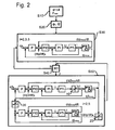
- Fig. 2 illustrates a corresponding regulation, which may be implemented for example in the arranged in a control cabinet 4 robot controller.
- a first step S10 preferably in advance, the Cartesian straight line s + ⁇ k in the working space, along which the robot is to be yielding, and control parameters, for example, a maximum force F max , from which the robot is to move, are specified.
- a leading axis in this case the third axis selected.
- the robot 1 moves with a pure position control of all axes 2, 3, 5 its starting pose.
- the third axis is compliant regulated.
- a desired current limit 10 is indicated in step S50.
- the control returns to a pure position control for all axes (S40: "N").
- a desired-actual adjustment of the axle positions is preferably carried out.
- this axis can, for example, be considered by an optimizer which takes the controllability and observability as quality criteria into account Axis, determined as a guide axis and the line of action according to (7) are given.
Applications Claiming Priority (3)
| Application Number | Priority Date | Filing Date | Title |
|---|---|---|---|
| DE200910018403 DE102009018403A1 (de) | 2009-04-22 | 2009-04-22 | Verfahren und Vorrichtung zur Regelung eines Manipulators |
| DE200910049327 DE102009049327A1 (de) | 2009-10-14 | 2009-10-14 | Verfahren und Kontrollvorrichtung zum Schweißen mittels einer Positioniervorrichtung |
| DE102009049329A DE102009049329A1 (de) | 2009-10-14 | 2009-10-14 | Verfahren und Vorrichtung zur Steuerung einer Positioniervorrichtung zum Schweißen |
Publications (3)
| Publication Number | Publication Date |
|---|---|
| EP2243602A2 EP2243602A2 (de) | 2010-10-27 |
| EP2243602A3 EP2243602A3 (de) | 2012-05-09 |
| EP2243602B1 true EP2243602B1 (de) | 2013-05-15 |
Family
ID=42320679
Family Applications (3)
| Application Number | Title | Priority Date | Filing Date |
|---|---|---|---|
| EP10003620.1A Active EP2243585B1 (de) | 2009-04-22 | 2010-03-31 | Verfahren und Vorrichtung zur Steuerung einer Positioniervorrichtung zum Schweißen |
| EP10003623.5A Active EP2243602B1 (de) | 2009-04-22 | 2010-03-31 | Verfahren und Vorrichtung zur Regelung eines Manipulators |
| EP10003621.9A Active EP2243586B1 (de) | 2009-04-22 | 2010-03-31 | Verfahren und Kontrollvorrichtung zum Schweißen mittels einer Positioniervorrichtung |
Family Applications Before (1)
| Application Number | Title | Priority Date | Filing Date |
|---|---|---|---|
| EP10003620.1A Active EP2243585B1 (de) | 2009-04-22 | 2010-03-31 | Verfahren und Vorrichtung zur Steuerung einer Positioniervorrichtung zum Schweißen |
Family Applications After (1)
| Application Number | Title | Priority Date | Filing Date |
|---|---|---|---|
| EP10003621.9A Active EP2243586B1 (de) | 2009-04-22 | 2010-03-31 | Verfahren und Kontrollvorrichtung zum Schweißen mittels einer Positioniervorrichtung |
Country Status (6)
| Country | Link |
|---|---|
| US (3) | US8249746B2 (zh) |
| EP (3) | EP2243585B1 (zh) |
| JP (1) | JP5971887B2 (zh) |
| KR (1) | KR101683289B1 (zh) |
| CN (1) | CN101890715B (zh) |
| ES (1) | ES2424244T3 (zh) |
Cited By (1)
| Publication number | Priority date | Publication date | Assignee | Title |
|---|---|---|---|---|
| DE102016105084A1 (de) | 2016-03-18 | 2017-09-21 | Dr. Ing. H.C. F. Porsche Aktiengesellschaft | Fügevorrichtung sowie Verfahren zum Betreiben einer Fügevorrichtung |
Families Citing this family (33)
| Publication number | Priority date | Publication date | Assignee | Title |
|---|---|---|---|---|
| EP2243585B1 (de) * | 2009-04-22 | 2018-08-08 | KUKA Deutschland GmbH | Verfahren und Vorrichtung zur Steuerung einer Positioniervorrichtung zum Schweißen |
| JP5572046B2 (ja) * | 2010-09-13 | 2014-08-13 | 株式会社神戸製鋼所 | 異材接合方法 |
| US9053394B2 (en) * | 2011-08-30 | 2015-06-09 | 5D Robotics, Inc. | Vehicle management system |
| DE102011087958A1 (de) | 2011-12-08 | 2013-06-13 | Kuka Roboter Gmbh | Schweißroboter |
| DE202011052430U1 (de) * | 2011-12-22 | 2013-03-25 | Kuka Systems Gmbh | Werkzeugwechselsystem |
| US20130197672A1 (en) * | 2012-01-26 | 2013-08-01 | Intuitive Surgical Operations, Inc. | Pass-Through Controller for Cascaded Proportional-Integral-Derivative Control Loops |
| US9144860B2 (en) * | 2012-03-29 | 2015-09-29 | Fanuc Robotics America Corporation | Robotic weld gun orientation normalization |
| DE202012101833U1 (de) * | 2012-05-18 | 2013-08-20 | Kuka Systems Gmbh | Mehrteiliges Werkzeug |
| JP6111562B2 (ja) * | 2012-08-31 | 2017-04-12 | セイコーエプソン株式会社 | ロボット |
| CA2895478C (en) * | 2012-12-18 | 2021-11-02 | Honda Motor Co., Ltd. | Robot control system and robot control method |
| EP3107429B1 (en) * | 2014-02-20 | 2023-11-15 | MBL Limited | Methods and systems for food preparation in a robotic cooking kitchen |
| JP5893666B2 (ja) | 2014-04-14 | 2016-03-23 | ファナック株式会社 | 力に応じて動かすロボットのロボット制御装置およびロボットシステム |
| JP6511626B2 (ja) * | 2014-04-18 | 2019-05-15 | 株式会社安川電機 | シーム溶接システム、シーム溶接方法および被溶接物の生産方法 |
| JP5845311B2 (ja) | 2014-04-30 | 2016-01-20 | ファナック株式会社 | ロボットの柔軟制御を行う制御装置 |
| CN104070525B (zh) * | 2014-06-18 | 2016-02-03 | 大连大学 | 用于空间机械臂连续轨迹跟踪的方法 |
| DE102014222809B3 (de) * | 2014-11-07 | 2016-01-14 | Kuka Roboter Gmbh | Event-basierte Redundanzwinkelkonfiguartion für Gelenkarmroboter |
| KR101630405B1 (ko) * | 2014-11-27 | 2016-06-15 | 한전원자력연료 주식회사 | 골격체 조립용 스폿 용접 장치 |
| DE102015204599B3 (de) * | 2015-03-13 | 2016-08-11 | Kuka Roboter Gmbh | Verfahren zur Steuerung eines Manipulators zur Ausführung eines Arbeitsprozesses |
| CN106200685B (zh) * | 2015-05-04 | 2019-03-19 | 中国科学院沈阳自动化研究所 | 非线性位置与速度的遥操作控制算法 |
| US9815198B2 (en) * | 2015-07-23 | 2017-11-14 | X Development Llc | System and method for determining a work offset |
| KR102312368B1 (ko) * | 2015-08-04 | 2021-10-12 | 한국전기연구원 | 여자유도 로봇 제어 시스템, 방법, 및 상기 방법을 실행시키기 위한 컴퓨터 판독 가능한 프로그램을 기록한 기록 매체 |
| CN105729460B (zh) * | 2016-04-20 | 2017-11-28 | 机器时代(北京)科技有限公司 | 柔性传动装置和可调弹簧和储能部件和锁合装置和机器人 |
| DE102016004841B4 (de) * | 2016-04-24 | 2018-01-04 | Kastanienbaum GmbH | Verfahren und Vorrichtung zum Festlegen eines Bewegungsablaufs für einen Roboter |
| DE102017102621B3 (de) * | 2017-02-09 | 2018-05-09 | Franka Emika Gmbh | Roboter |
| DE102017121095A1 (de) * | 2017-09-12 | 2019-03-14 | Matuschek Meßtechnik GmbH | Verfahren und Vorrichtung zur Messung einer Elektrodenkraft einer Schweißzange |
| JP7148321B2 (ja) * | 2018-08-20 | 2022-10-05 | ファナック株式会社 | 多関節ロボットの制御装置 |
| CN109333530B (zh) * | 2018-10-08 | 2020-05-26 | 浙江工业大学 | 一种基于串联弹性执行器的六关节机械臂接触力控制方法 |
| CN109732614A (zh) * | 2019-03-19 | 2019-05-10 | 合肥工业大学 | 基于约束力的scara机器人的控制设计方法及其装置及控制器 |
| JP7015267B2 (ja) * | 2019-03-29 | 2022-02-02 | ファナック株式会社 | ロボット制御装置及びロボットシステム |
| CN110154022B (zh) * | 2019-05-20 | 2020-10-30 | 南京航浦机械科技有限公司 | 一种基于定向刚度模型的机器人制孔径向定位修正方法 |
| CN112223302B (zh) * | 2020-12-17 | 2021-02-26 | 国网瑞嘉(天津)智能机器人有限公司 | 基于多传感器的带电作业机器人的快速标定方法及装置 |
| CN112549085B (zh) * | 2021-02-25 | 2021-05-18 | 辽宁省医疗器械检验检测院 | 一种基于视觉补偿的机械臂偏移检测系统及方法 |
| CN113319876B (zh) * | 2021-06-28 | 2023-02-03 | 北京邮电大学 | 一种由流体驱动的多指仿人灵巧手 |
Family Cites Families (47)
| Publication number | Priority date | Publication date | Assignee | Title |
|---|---|---|---|---|
| IT1165233B (it) * | 1979-09-25 | 1987-04-22 | Fiat Ricerche | Trasduttore a sei gradi di liberta particolarmente per robot |
| DE3018384A1 (de) * | 1980-05-14 | 1981-11-19 | Rossell Electronique S.A., Lausanne | Verfahren zum zubringen von mindestens einer elektrode, zubringevorrichtung und aufnehmer zur ausfuehrung dieses verfahrens sowie verwendung des verfahrens, der zubringevorrichtung und/oder des aufnehmers |
| FR2539346B1 (fr) * | 1983-01-18 | 1990-12-07 | Mitsubishi Electric Corp | Dispositif manipulateur automatique articule notamment pour le soudage a l'arc |
| DE3503675A1 (de) * | 1985-02-04 | 1986-08-07 | L. & C. Steinmüller GmbH, 5270 Gummersbach | Verfahren und vorrichtung zum mechanisch gesteuerten brennschneiden und/oder verbindungsschweissen von werkstuecken |
| JPS6356369A (ja) * | 1986-08-27 | 1988-03-10 | Mitsubishi Electric Corp | 溶接機ヘツド |
| US4860215A (en) * | 1987-04-06 | 1989-08-22 | California Institute Of Technology | Method and apparatus for adaptive force and position control of manipulators |
| JPH0683976B2 (ja) * | 1988-03-15 | 1994-10-26 | インターナシヨナル・ビジネス・マシーンズ・コーポレーシヨン | コンプライアンス制御方法 |
| JPH0832401B2 (ja) * | 1988-09-08 | 1996-03-29 | 川崎重工業株式会社 | 産業用ロボット |
| JP2604929B2 (ja) * | 1991-12-03 | 1997-04-30 | 山武ハネウエル株式会社 | ロボットの制御装置 |
| DE4332807C2 (de) * | 1992-10-20 | 2002-07-18 | Schlattl Werner Bavaria Tech | Opto-elektrischer Sensor |
| JPH06309040A (ja) * | 1993-04-21 | 1994-11-04 | Daikin Ind Ltd | ロボットアームの制御装置 |
| US5504298A (en) * | 1993-06-04 | 1996-04-02 | Axis Usa, Inc. | Methods and apparatus for detecting electrode separation |
| JP3114440B2 (ja) * | 1993-07-22 | 2000-12-04 | 日産自動車株式会社 | スポット溶接装置 |
| JPH0760457A (ja) * | 1993-08-26 | 1995-03-07 | Na Detsukusu:Kk | 抵抗溶接機 |
| DE19524486A1 (de) * | 1995-07-05 | 1997-01-09 | Schlattl Werner Bavaria Tech | Schweißeinrichtung |
| JP3890634B2 (ja) * | 1995-09-19 | 2007-03-07 | セイコーエプソン株式会社 | 圧電体薄膜素子及びインクジェット式記録ヘッド |
| US6193142B1 (en) * | 1996-12-25 | 2001-02-27 | Nissan Motor Co., Ltd. | Assembling apparatus assembling body side of automotive vehicle and assembling method thereof |
| US5988486A (en) * | 1997-03-11 | 1999-11-23 | Honda Giken Kogyo Kabushiki Kaisha | Method of controlling electrode force of spot welding gun |
| JP3886603B2 (ja) * | 1997-07-14 | 2007-02-28 | 株式会社ナ・デックス | 単位体積当たりの累積発熱量を指標とする抵抗溶接システム |
| JP3761344B2 (ja) * | 1998-12-01 | 2006-03-29 | トヨタ自動車株式会社 | 溶接ガンとそれを用いたセンサー校正方法、溶接制御方法、溶接打点位置精度変化管理方法 |
| JP3443077B2 (ja) * | 1999-09-20 | 2003-09-02 | ソニー株式会社 | ロボットの運動パターン生成装置及び運動パターン生成方法、並びにロボット |
| DE19948880A1 (de) * | 1999-10-08 | 2001-04-12 | Smb Schwede Maschb Gmbh | Schweißkopf für eine Bandumreifungsmaschine |
| JP3615702B2 (ja) * | 1999-11-25 | 2005-02-02 | ソニー株式会社 | 脚式移動ロボットの動作制御装置及び動作制御方法、並びに、脚式移動ロボット |
| JP3473834B2 (ja) * | 1999-11-29 | 2003-12-08 | 株式会社安川電機 | ロボットの制御装置 |
| PT1253991E (pt) * | 2000-02-09 | 2004-02-27 | Reu Schweisstechnik Gmbh | Dispositivo e processo de comando de soldadura resistiva por pontos |
| US7102098B2 (en) * | 2000-12-08 | 2006-09-05 | L'Air Liquide - Societe Anonyme a Directoire et Counseil de Surveillance pour l'Etude et l'Exploitataion des Procedes Georges Claude | Method and system for solving a problem arising during a welding operation or the like |
| JP3603279B2 (ja) * | 2001-09-26 | 2004-12-22 | 独立行政法人科学技術振興機構 | 二脚歩行式人型ロボット |
| DE10338176A1 (de) * | 2003-08-20 | 2005-03-24 | Kuka Roboter Gmbh | Verfahren und Vorrichtung zum Steuern der Andruckkraft einer Schweißzange |
| JP4592276B2 (ja) * | 2003-10-24 | 2010-12-01 | ソニー株式会社 | ロボット装置のためのモーション編集装置及びモーション編集方法、並びにコンピュータ・プログラム |
| JP4513320B2 (ja) * | 2003-12-17 | 2010-07-28 | ソニー株式会社 | ロボット装置、並びにロボット装置の運動制御方法 |
| SE0400320D0 (sv) * | 2004-02-06 | 2004-02-06 | Abb Ab | Control method for robots |
| US9110456B2 (en) * | 2004-09-08 | 2015-08-18 | Abb Research Ltd. | Robotic machining with a flexible manipulator |
| JP4531520B2 (ja) * | 2004-10-15 | 2010-08-25 | 本田技研工業株式会社 | 脚式移動ロボットの制御装置 |
| JP4440761B2 (ja) * | 2004-12-24 | 2010-03-24 | 本田技研工業株式会社 | 脚式移動ロボットの制御装置 |
| JP4899175B2 (ja) * | 2005-04-28 | 2012-03-21 | 株式会社不二越 | スポット溶接方法とスポット溶接システム |
| US20070075048A1 (en) * | 2005-09-30 | 2007-04-05 | Nachi-Fujikoshi Corp. | Welding teaching point correction system and calibration method |
| JP4202365B2 (ja) * | 2006-03-07 | 2008-12-24 | ファナック株式会社 | 力制御装置 |
| WO2008004487A1 (fr) * | 2006-07-04 | 2008-01-10 | Panasonic Corporation | Appareil et procédé de commande de bras robotisé, robot et programme de commande de bras robotisé |
| JP2008073830A (ja) * | 2006-09-25 | 2008-04-03 | Fanuc Ltd | ロボット制御装置 |
| JP2008302449A (ja) * | 2007-06-06 | 2008-12-18 | Fanuc Ltd | ロボット制御装置 |
| JP4233584B2 (ja) * | 2007-06-18 | 2009-03-04 | ファナック株式会社 | スポット溶接ロボットの位置決め方法 |
| JP2009066685A (ja) * | 2007-09-11 | 2009-04-02 | Sony Corp | ロボット装置及びロボット装置の制御方法 |
| DE112008003101T5 (de) * | 2007-11-14 | 2010-10-14 | Hamamatsu Photonics K.K., Hamamatsu | Laser-Bearbeitungsvorrichtung und Laser-Bearbeitungsverfahren |
| EP2149421B1 (de) * | 2008-07-30 | 2011-11-30 | IPG Photonics Corporation | Laser-Schweißwerkzeug mit einem Faserlaser |
| EP2243585B1 (de) * | 2009-04-22 | 2018-08-08 | KUKA Deutschland GmbH | Verfahren und Vorrichtung zur Steuerung einer Positioniervorrichtung zum Schweißen |
| US8634950B2 (en) * | 2009-12-14 | 2014-01-21 | Embraer S.A. | Automated positioning and alignment method and system for aircraft structures using robots |
| DE102010024238A1 (de) * | 2010-06-18 | 2011-12-22 | Kuka Laboratories Gmbh | Verfahren und Vorrichtung zur Überwachung einer bewegungsgesteuerten Maschine mit einem elektronisch kommutierten Antriebsmotor |
-
2010
- 2010-03-31 EP EP10003620.1A patent/EP2243585B1/de active Active
- 2010-03-31 EP EP10003623.5A patent/EP2243602B1/de active Active
- 2010-03-31 ES ES10003623T patent/ES2424244T3/es active Active
- 2010-03-31 EP EP10003621.9A patent/EP2243586B1/de active Active
- 2010-04-21 KR KR1020100036833A patent/KR101683289B1/ko active IP Right Grant
- 2010-04-21 JP JP2010097899A patent/JP5971887B2/ja active Active
- 2010-04-22 US US12/765,124 patent/US8249746B2/en active Active
- 2010-04-22 US US12/765,077 patent/US20100270271A1/en not_active Abandoned
- 2010-04-22 CN CN201010153831.4A patent/CN101890715B/zh active Active
- 2010-04-22 US US12/765,104 patent/US8395081B2/en active Active
Cited By (1)
| Publication number | Priority date | Publication date | Assignee | Title |
|---|---|---|---|---|
| DE102016105084A1 (de) | 2016-03-18 | 2017-09-21 | Dr. Ing. H.C. F. Porsche Aktiengesellschaft | Fügevorrichtung sowie Verfahren zum Betreiben einer Fügevorrichtung |
Also Published As
| Publication number | Publication date |
|---|---|
| ES2424244T3 (es) | 2013-09-30 |
| EP2243586A1 (de) | 2010-10-27 |
| US20100270271A1 (en) | 2010-10-28 |
| EP2243585B1 (de) | 2018-08-08 |
| CN101890715B (zh) | 2015-04-29 |
| KR101683289B1 (ko) | 2016-12-06 |
| US20100270272A1 (en) | 2010-10-28 |
| EP2243602A3 (de) | 2012-05-09 |
| US8395081B2 (en) | 2013-03-12 |
| JP5971887B2 (ja) | 2016-08-17 |
| EP2243585A1 (de) | 2010-10-27 |
| JP2010253676A (ja) | 2010-11-11 |
| EP2243602A2 (de) | 2010-10-27 |
| CN101890715A (zh) | 2010-11-24 |
| US20100274388A1 (en) | 2010-10-28 |
| EP2243586B1 (de) | 2014-07-02 |
| US8249746B2 (en) | 2012-08-21 |
| KR20100116545A (ko) | 2010-11-01 |
Similar Documents
| Publication | Publication Date | Title |
|---|---|---|
| EP2243602B1 (de) | Verfahren und Vorrichtung zur Regelung eines Manipulators | |
| DE102009018403A1 (de) | Verfahren und Vorrichtung zur Regelung eines Manipulators | |
| EP3323026B1 (de) | Ermitteln eines eingabebefehls für einen roboter, der durch manuelles ausüben einer kraft auf den roboter eingegeben wird | |
| DE102015004475B4 (de) | Robotersteuervorrichtung zum Steuern eines Roboters, der gemäß einer aufgebrachten Kraft bewegt wird | |
| DE102008027008B4 (de) | Verfahren und Vorrichtung zum Steuern eines Manipulators | |
| EP1950010B1 (de) | Roboter und Verfahren zum Programmieren eines Roboters | |
| DE102009049172B4 (de) | Verfahren und Vorrichtung zur Steuerung eines Manipulators | |
| EP2563553B1 (de) | Verfahren und steuermittel zum steuern eines roboters | |
| DE112016005365B4 (de) | Direktes Lehrverfahren eines Roboters | |
| EP2073084B1 (de) | Verfahren und Einrichtung zur Steuerung eines Roboter Manipulators | |
| EP2303521B1 (de) | Industrieroboter und bahnplanungsverfahren zum steuern der bewegung eines industrieroboters | |
| EP2546711B1 (de) | Verfahren zum Programmieren eines Roboters | |
| DE102015004481B4 (de) | Robotersteuervorrichtung zum Steuern eines gemäß einer ausgeübten Kraft bewegten Roboters | |
| EP1591209A2 (de) | Verfahren zum Steuern einer Maschine, insbesondere eines Industrieroboters | |
| EP2868445A1 (de) | Verfahren zum Programmieren von Bewegungsabläufen eines redundanten Industrieroboters und zugehöriger Industrieroboter | |
| EP2218556B1 (de) | Steuerung und Steuerungsverfahren für einen Manipulator | |
| EP2255931A2 (de) | Verfahren und Vorrichtung zur Steuerung eines Manipulators | |
| EP2070665A2 (de) | Verfahren und Vorrichtung zur Bereichsüberwachung eines Manipulators | |
| DE102018210864B3 (de) | Verfahren und System zum Regeln eines Roboters | |
| EP3812106B1 (de) | Roboteranordnung, verfahren zum betreiben der roboteranordnung, computerprogramm sowie maschinenlesbares speichermedium | |
| DE102018214257B3 (de) | Roboterregelung | |
| DE102018200864B3 (de) | Verfahren und System zum Steuern eines Roboters | |
| DE102012022190B4 (de) | Inverse Kinematik | |
| DE102021113636B3 (de) | Verfahren zum Bestimmen externer Interaktionskräfte und/oder Interaktionsmomente eines Roboters, Roboter und Computerprogrammprodukt | |
| DE102018209044B3 (de) | Kraftregelung eines Roboters |
Legal Events
| Date | Code | Title | Description |
|---|---|---|---|
| PUAI | Public reference made under article 153(3) epc to a published international application that has entered the european phase |
Free format text: ORIGINAL CODE: 0009012 |
|
| AK | Designated contracting states |
Kind code of ref document: A2 Designated state(s): AT BE BG CH CY CZ DE DK EE ES FI FR GB GR HR HU IE IS IT LI LT LU LV MC MK MT NL NO PL PT RO SE SI SK SM TR |
|
| AX | Request for extension of the european patent |
Extension state: AL BA ME RS |
|
| TPAC | Observations filed by third parties |
Free format text: ORIGINAL CODE: EPIDOSNTIPA |
|
| PUAL | Search report despatched |
Free format text: ORIGINAL CODE: 0009013 |
|
| RIC1 | Information provided on ipc code assigned before grant |
Ipc: B23K 11/25 20060101ALN20120328BHEP Ipc: B23K 11/31 20060101ALN20120328BHEP Ipc: B25J 9/16 20060101AFI20120328BHEP |
|
| AK | Designated contracting states |
Kind code of ref document: A3 Designated state(s): AT BE BG CH CY CZ DE DK EE ES FI FR GB GR HR HU IE IS IT LI LT LU LV MC MK MT NL NO PL PT RO SE SI SK SM TR |
|
| AX | Request for extension of the european patent |
Extension state: AL BA ME RS |
|
| 17P | Request for examination filed |
Effective date: 20120801 |
|
| GRAP | Despatch of communication of intention to grant a patent |
Free format text: ORIGINAL CODE: EPIDOSNIGR1 |
|
| RIC1 | Information provided on ipc code assigned before grant |
Ipc: B23K 11/25 20060101ALN20120911BHEP Ipc: B23K 11/31 20060101ALN20120911BHEP Ipc: B25J 9/16 20060101AFI20120911BHEP |
|
| RIC1 | Information provided on ipc code assigned before grant |
Ipc: B23K 11/31 20060101ALN20121008BHEP Ipc: B25J 9/16 20060101AFI20121008BHEP Ipc: B23K 11/25 20060101ALN20121008BHEP |
|
| GRAP | Despatch of communication of intention to grant a patent |
Free format text: ORIGINAL CODE: EPIDOSNIGR1 |
|
| RIC1 | Information provided on ipc code assigned before grant |
Ipc: B23K 11/31 20060101ALN20121122BHEP Ipc: B23K 11/25 20060101ALN20121122BHEP Ipc: B25J 9/16 20060101AFI20121122BHEP |
|
| GRAS | Grant fee paid |
Free format text: ORIGINAL CODE: EPIDOSNIGR3 |
|
| GRAA | (expected) grant |
Free format text: ORIGINAL CODE: 0009210 |
|
| AK | Designated contracting states |
Kind code of ref document: B1 Designated state(s): AT BE BG CH CY CZ DE DK EE ES FI FR GB GR HR HU IE IS IT LI LT LU LV MC MK MT NL NO PL PT RO SE SI SK SM TR |
|
| REG | Reference to a national code |
Ref country code: CH Ref legal event code: EP Ref country code: GB Ref legal event code: FG4D Free format text: NOT ENGLISH |
|
| REG | Reference to a national code |
Ref country code: AT Ref legal event code: REF Ref document number: 611881 Country of ref document: AT Kind code of ref document: T Effective date: 20130615 |
|
| REG | Reference to a national code |
Ref country code: IE Ref legal event code: FG4D Free format text: LANGUAGE OF EP DOCUMENT: GERMAN |
|
| REG | Reference to a national code |
Ref country code: DE Ref legal event code: R096 Ref document number: 502010003312 Country of ref document: DE Effective date: 20130711 |
|
| REG | Reference to a national code |
Ref country code: SE Ref legal event code: TRGR |
|
| REG | Reference to a national code |
Ref country code: ES Ref legal event code: FG2A Ref document number: 2424244 Country of ref document: ES Kind code of ref document: T3 Effective date: 20130930 |
|
| REG | Reference to a national code |
Ref country code: LT Ref legal event code: MG4D |
|
| REG | Reference to a national code |
Ref country code: NL Ref legal event code: VDEP Effective date: 20130515 |
|
| PG25 | Lapsed in a contracting state [announced via postgrant information from national office to epo] |
Ref country code: GR Free format text: LAPSE BECAUSE OF FAILURE TO SUBMIT A TRANSLATION OF THE DESCRIPTION OR TO PAY THE FEE WITHIN THE PRESCRIBED TIME-LIMIT Effective date: 20130816 Ref country code: FI Free format text: LAPSE BECAUSE OF FAILURE TO SUBMIT A TRANSLATION OF THE DESCRIPTION OR TO PAY THE FEE WITHIN THE PRESCRIBED TIME-LIMIT Effective date: 20130515 Ref country code: LT Free format text: LAPSE BECAUSE OF FAILURE TO SUBMIT A TRANSLATION OF THE DESCRIPTION OR TO PAY THE FEE WITHIN THE PRESCRIBED TIME-LIMIT Effective date: 20130515 Ref country code: SI Free format text: LAPSE BECAUSE OF FAILURE TO SUBMIT A TRANSLATION OF THE DESCRIPTION OR TO PAY THE FEE WITHIN THE PRESCRIBED TIME-LIMIT Effective date: 20130515 Ref country code: NO Free format text: LAPSE BECAUSE OF FAILURE TO SUBMIT A TRANSLATION OF THE DESCRIPTION OR TO PAY THE FEE WITHIN THE PRESCRIBED TIME-LIMIT Effective date: 20130815 Ref country code: IS Free format text: LAPSE BECAUSE OF FAILURE TO SUBMIT A TRANSLATION OF THE DESCRIPTION OR TO PAY THE FEE WITHIN THE PRESCRIBED TIME-LIMIT Effective date: 20130915 Ref country code: PT Free format text: LAPSE BECAUSE OF FAILURE TO SUBMIT A TRANSLATION OF THE DESCRIPTION OR TO PAY THE FEE WITHIN THE PRESCRIBED TIME-LIMIT Effective date: 20130916 |
|
| PG25 | Lapsed in a contracting state [announced via postgrant information from national office to epo] |
Ref country code: PL Free format text: LAPSE BECAUSE OF FAILURE TO SUBMIT A TRANSLATION OF THE DESCRIPTION OR TO PAY THE FEE WITHIN THE PRESCRIBED TIME-LIMIT Effective date: 20130515 Ref country code: HR Free format text: LAPSE BECAUSE OF FAILURE TO SUBMIT A TRANSLATION OF THE DESCRIPTION OR TO PAY THE FEE WITHIN THE PRESCRIBED TIME-LIMIT Effective date: 20130515 Ref country code: BG Free format text: LAPSE BECAUSE OF FAILURE TO SUBMIT A TRANSLATION OF THE DESCRIPTION OR TO PAY THE FEE WITHIN THE PRESCRIBED TIME-LIMIT Effective date: 20130815 |
|
| PG25 | Lapsed in a contracting state [announced via postgrant information from national office to epo] |
Ref country code: LV Free format text: LAPSE BECAUSE OF FAILURE TO SUBMIT A TRANSLATION OF THE DESCRIPTION OR TO PAY THE FEE WITHIN THE PRESCRIBED TIME-LIMIT Effective date: 20130515 |
|
| PG25 | Lapsed in a contracting state [announced via postgrant information from national office to epo] |
Ref country code: CZ Free format text: LAPSE BECAUSE OF FAILURE TO SUBMIT A TRANSLATION OF THE DESCRIPTION OR TO PAY THE FEE WITHIN THE PRESCRIBED TIME-LIMIT Effective date: 20130515 Ref country code: SK Free format text: LAPSE BECAUSE OF FAILURE TO SUBMIT A TRANSLATION OF THE DESCRIPTION OR TO PAY THE FEE WITHIN THE PRESCRIBED TIME-LIMIT Effective date: 20130515 Ref country code: EE Free format text: LAPSE BECAUSE OF FAILURE TO SUBMIT A TRANSLATION OF THE DESCRIPTION OR TO PAY THE FEE WITHIN THE PRESCRIBED TIME-LIMIT Effective date: 20130515 Ref country code: DK Free format text: LAPSE BECAUSE OF FAILURE TO SUBMIT A TRANSLATION OF THE DESCRIPTION OR TO PAY THE FEE WITHIN THE PRESCRIBED TIME-LIMIT Effective date: 20130515 |
|
| PG25 | Lapsed in a contracting state [announced via postgrant information from national office to epo] |
Ref country code: NL Free format text: LAPSE BECAUSE OF FAILURE TO SUBMIT A TRANSLATION OF THE DESCRIPTION OR TO PAY THE FEE WITHIN THE PRESCRIBED TIME-LIMIT Effective date: 20130515 Ref country code: RO Free format text: LAPSE BECAUSE OF FAILURE TO SUBMIT A TRANSLATION OF THE DESCRIPTION OR TO PAY THE FEE WITHIN THE PRESCRIBED TIME-LIMIT Effective date: 20130515 |
|
| PLBE | No opposition filed within time limit |
Free format text: ORIGINAL CODE: 0009261 |
|
| STAA | Information on the status of an ep patent application or granted ep patent |
Free format text: STATUS: NO OPPOSITION FILED WITHIN TIME LIMIT |
|
| 26N | No opposition filed |
Effective date: 20140218 |
|
| REG | Reference to a national code |
Ref country code: DE Ref legal event code: R097 Ref document number: 502010003312 Country of ref document: DE Effective date: 20140218 |
|
| PG25 | Lapsed in a contracting state [announced via postgrant information from national office to epo] |
Ref country code: LU Free format text: LAPSE BECAUSE OF FAILURE TO SUBMIT A TRANSLATION OF THE DESCRIPTION OR TO PAY THE FEE WITHIN THE PRESCRIBED TIME-LIMIT Effective date: 20140331 |
|
| REG | Reference to a national code |
Ref country code: CH Ref legal event code: PL |
|
| GBPC | Gb: european patent ceased through non-payment of renewal fee |
Effective date: 20140331 |
|
| REG | Reference to a national code |
Ref country code: IE Ref legal event code: MM4A |
|
| PG25 | Lapsed in a contracting state [announced via postgrant information from national office to epo] |
Ref country code: LI Free format text: LAPSE BECAUSE OF NON-PAYMENT OF DUE FEES Effective date: 20140331 Ref country code: CH Free format text: LAPSE BECAUSE OF NON-PAYMENT OF DUE FEES Effective date: 20140331 Ref country code: GB Free format text: LAPSE BECAUSE OF NON-PAYMENT OF DUE FEES Effective date: 20140331 Ref country code: IE Free format text: LAPSE BECAUSE OF NON-PAYMENT OF DUE FEES Effective date: 20140331 |
|
| REG | Reference to a national code |
Ref country code: FR Ref legal event code: PLFP Year of fee payment: 7 |
|
| PG25 | Lapsed in a contracting state [announced via postgrant information from national office to epo] |
Ref country code: MT Free format text: LAPSE BECAUSE OF FAILURE TO SUBMIT A TRANSLATION OF THE DESCRIPTION OR TO PAY THE FEE WITHIN THE PRESCRIBED TIME-LIMIT Effective date: 20130515 |
|
| PG25 | Lapsed in a contracting state [announced via postgrant information from national office to epo] |
Ref country code: SM Free format text: LAPSE BECAUSE OF FAILURE TO SUBMIT A TRANSLATION OF THE DESCRIPTION OR TO PAY THE FEE WITHIN THE PRESCRIBED TIME-LIMIT Effective date: 20130515 |
|
| REG | Reference to a national code |
Ref country code: AT Ref legal event code: MM01 Ref document number: 611881 Country of ref document: AT Kind code of ref document: T Effective date: 20150331 |
|
| PG25 | Lapsed in a contracting state [announced via postgrant information from national office to epo] |
Ref country code: MC Free format text: LAPSE BECAUSE OF FAILURE TO SUBMIT A TRANSLATION OF THE DESCRIPTION OR TO PAY THE FEE WITHIN THE PRESCRIBED TIME-LIMIT Effective date: 20130515 |
|
| PG25 | Lapsed in a contracting state [announced via postgrant information from national office to epo] |
Ref country code: CY Free format text: LAPSE BECAUSE OF FAILURE TO SUBMIT A TRANSLATION OF THE DESCRIPTION OR TO PAY THE FEE WITHIN THE PRESCRIBED TIME-LIMIT Effective date: 20130515 |
|
| PG25 | Lapsed in a contracting state [announced via postgrant information from national office to epo] |
Ref country code: HU Free format text: LAPSE BECAUSE OF FAILURE TO SUBMIT A TRANSLATION OF THE DESCRIPTION OR TO PAY THE FEE WITHIN THE PRESCRIBED TIME-LIMIT; INVALID AB INITIO Effective date: 20100331 Ref country code: TR Free format text: LAPSE BECAUSE OF FAILURE TO SUBMIT A TRANSLATION OF THE DESCRIPTION OR TO PAY THE FEE WITHIN THE PRESCRIBED TIME-LIMIT Effective date: 20130515 |
|
| PG25 | Lapsed in a contracting state [announced via postgrant information from national office to epo] |
Ref country code: AT Free format text: LAPSE BECAUSE OF NON-PAYMENT OF DUE FEES Effective date: 20150331 |
|
| REG | Reference to a national code |
Ref country code: FR Ref legal event code: PLFP Year of fee payment: 8 |
|
| PG25 | Lapsed in a contracting state [announced via postgrant information from national office to epo] |
Ref country code: BE Free format text: LAPSE BECAUSE OF NON-PAYMENT OF DUE FEES Effective date: 20140331 |
|
| REG | Reference to a national code |
Ref country code: FR Ref legal event code: PLFP Year of fee payment: 9 |
|
| PG25 | Lapsed in a contracting state [announced via postgrant information from national office to epo] |
Ref country code: MK Free format text: LAPSE BECAUSE OF FAILURE TO SUBMIT A TRANSLATION OF THE DESCRIPTION OR TO PAY THE FEE WITHIN THE PRESCRIBED TIME-LIMIT Effective date: 20130515 |
|
| REG | Reference to a national code |
Ref country code: DE Ref legal event code: R082 Ref document number: 502010003312 Country of ref document: DE Representative=s name: WALLINGER RICKER SCHLOTTER TOSTMANN PATENT- UN, DE Ref country code: DE Ref legal event code: R081 Ref document number: 502010003312 Country of ref document: DE Owner name: KUKA DEUTSCHLAND GMBH, DE Free format text: FORMER OWNER: KUKA ROBOTER GMBH, 86165 AUGSBURG, DE |
|
| PGFP | Annual fee paid to national office [announced via postgrant information from national office to epo] |
Ref country code: FR Payment date: 20230208 Year of fee payment: 14 |
|
| PGFP | Annual fee paid to national office [announced via postgrant information from national office to epo] |
Ref country code: SE Payment date: 20230210 Year of fee payment: 14 Ref country code: IT Payment date: 20230213 Year of fee payment: 14 Ref country code: DE Payment date: 20230131 Year of fee payment: 14 |
|
| P01 | Opt-out of the competence of the unified patent court (upc) registered |
Effective date: 20230528 |
|
| PGFP | Annual fee paid to national office [announced via postgrant information from national office to epo] |
Ref country code: ES Payment date: 20230405 Year of fee payment: 14 |