EP2216882B1 - Procédé de fabrication d'un noyau de stator feuilleté - Google Patents
Procédé de fabrication d'un noyau de stator feuilleté Download PDFInfo
- Publication number
- EP2216882B1 EP2216882B1 EP08855573.5A EP08855573A EP2216882B1 EP 2216882 B1 EP2216882 B1 EP 2216882B1 EP 08855573 A EP08855573 A EP 08855573A EP 2216882 B1 EP2216882 B1 EP 2216882B1
- Authority
- EP
- European Patent Office
- Prior art keywords
- core
- strip
- sheets
- core sheets
- sheet
- Prior art date
- Legal status (The legal status is an assumption and is not a legal conclusion. Google has not performed a legal analysis and makes no representation as to the accuracy of the status listed.)
- Not-in-force
Links
Images


Classifications
-
- H—ELECTRICITY
- H02—GENERATION; CONVERSION OR DISTRIBUTION OF ELECTRIC POWER
- H02K—DYNAMO-ELECTRIC MACHINES
- H02K15/00—Methods or apparatus specially adapted for manufacturing, assembling, maintaining or repairing of dynamo-electric machines
- H02K15/02—Methods or apparatus specially adapted for manufacturing, assembling, maintaining or repairing of dynamo-electric machines of stator or rotor bodies
- H02K15/024—Methods or apparatus specially adapted for manufacturing, assembling, maintaining or repairing of dynamo-electric machines of stator or rotor bodies with slots
-
- B—PERFORMING OPERATIONS; TRANSPORTING
- B21—MECHANICAL METAL-WORKING WITHOUT ESSENTIALLY REMOVING MATERIAL; PUNCHING METAL
- B21D—WORKING OR PROCESSING OF SHEET METAL OR METAL TUBES, RODS OR PROFILES WITHOUT ESSENTIALLY REMOVING MATERIAL; PUNCHING METAL
- B21D28/00—Shaping by press-cutting; Perforating
- B21D28/02—Punching blanks or articles with or without obtaining scrap; Notching
- B21D28/06—Making more than one part out of the same blank; Scrapless working
-
- B—PERFORMING OPERATIONS; TRANSPORTING
- B21—MECHANICAL METAL-WORKING WITHOUT ESSENTIALLY REMOVING MATERIAL; PUNCHING METAL
- B21D—WORKING OR PROCESSING OF SHEET METAL OR METAL TUBES, RODS OR PROFILES WITHOUT ESSENTIALLY REMOVING MATERIAL; PUNCHING METAL
- B21D43/00—Feeding, positioning or storing devices combined with, or arranged in, or specially adapted for use in connection with, apparatus for working or processing sheet metal, metal tubes or metal profiles; Associations therewith of cutting devices
- B21D43/02—Advancing work in relation to the stroke of the die or tool
-
- H—ELECTRICITY
- H02—GENERATION; CONVERSION OR DISTRIBUTION OF ELECTRIC POWER
- H02K—DYNAMO-ELECTRIC MACHINES
- H02K1/00—Details of the magnetic circuit
- H02K1/06—Details of the magnetic circuit characterised by the shape, form or construction
- H02K1/12—Stationary parts of the magnetic circuit
- H02K1/14—Stator cores with salient poles
- H02K1/146—Stator cores with salient poles consisting of a generally annular yoke with salient poles
-
- H—ELECTRICITY
- H02—GENERATION; CONVERSION OR DISTRIBUTION OF ELECTRIC POWER
- H02K—DYNAMO-ELECTRIC MACHINES
- H02K1/00—Details of the magnetic circuit
- H02K1/06—Details of the magnetic circuit characterised by the shape, form or construction
- H02K1/12—Stationary parts of the magnetic circuit
- H02K1/16—Stator cores with slots for windings
-
- H—ELECTRICITY
- H02—GENERATION; CONVERSION OR DISTRIBUTION OF ELECTRIC POWER
- H02K—DYNAMO-ELECTRIC MACHINES
- H02K15/00—Methods or apparatus specially adapted for manufacturing, assembling, maintaining or repairing of dynamo-electric machines
- H02K15/02—Methods or apparatus specially adapted for manufacturing, assembling, maintaining or repairing of dynamo-electric machines of stator or rotor bodies
- H02K15/022—Methods or apparatus specially adapted for manufacturing, assembling, maintaining or repairing of dynamo-electric machines of stator or rotor bodies with salient poles or claw-shaped poles
-
- H—ELECTRICITY
- H02—GENERATION; CONVERSION OR DISTRIBUTION OF ELECTRIC POWER
- H02K—DYNAMO-ELECTRIC MACHINES
- H02K5/00—Casings; Enclosures; Supports
- H02K5/04—Casings or enclosures characterised by the shape, form or construction thereof
- H02K5/18—Casings or enclosures characterised by the shape, form or construction thereof with ribs or fins for improving heat transfer
-
- Y—GENERAL TAGGING OF NEW TECHNOLOGICAL DEVELOPMENTS; GENERAL TAGGING OF CROSS-SECTIONAL TECHNOLOGIES SPANNING OVER SEVERAL SECTIONS OF THE IPC; TECHNICAL SUBJECTS COVERED BY FORMER USPC CROSS-REFERENCE ART COLLECTIONS [XRACs] AND DIGESTS
- Y10—TECHNICAL SUBJECTS COVERED BY FORMER USPC
- Y10T—TECHNICAL SUBJECTS COVERED BY FORMER US CLASSIFICATION
- Y10T29/00—Metal working
- Y10T29/49—Method of mechanical manufacture
- Y10T29/49002—Electrical device making
- Y10T29/49009—Dynamoelectric machine
Definitions
- the present invention relates to a laminated stator core and a method for manufacturing the same, capable of improving material yields and compensating variations in the thickness of a material strip.
- core sheets having an identical shape are blanked from a material strip and interlocked with one another inside dies.
- the core sheets are rotated prior to being laminated.
- outlines of the laminated core need to have rotational symmetries regardless of a rotational angle of the core sheets.
- full blanking (blanking a whole outline at a time) is generally used.
- the full blanking generates a lot of material scraps, resulting in poor yields of the material.
- Patent Documents 1 and 2 employ a scrapless blanking as the blank layout to improve material yields and a multiline alignment of the core sheets to enable effective use of the strip.
- JP 08-331780 discloses a laminated stator core formed by rotating by 90 degrees and laminating square iron core sheets of which corner portions are made to be circular-arc shaped and having a projection provided on one side of each square.
- this laminated stator core four projection (fin) pieces for the purpose of cooling are formed on each side.
- a center of a rotor space of the laminated stator core and a center of the square iron core sheets are aligned with one another.
- JP 2001-103691 discloses a stator core in which projections and recesses that act as cooling fins are circumferentially formed on a laminated stator core by rotating by 90 degrees and laminating each single core sheet or every plural numbers of core sheets.
- EP 1 686 674 discloses iron core sheets which are not rectangular, and the iron core sheets are regular-polygonal or circular. A center of each of the iron core sheets and a center of a rotor space are aligned with one another.
- the scrapless blanking in the Patent Document 1 or 2 is unable to punch out the core sheets along the outlines thereof within a required accuracy because the material strips have variation in width and lateral ends of the strips are partly used as the outlines of the core sheets. Furthermore, the scrapless blanking generates burrs due to double cuttings, resulting in dents on the core sheets or frictional wear of cutting tools. Thus, in the blanking process, to prevent the cutting tools from contacting the outlines of the core sheets that have been punched out in the previous processes, each die needs to have an allowance and round corners especially when the material strip has some irregularities in feeding intervals or width tolerances.
- the core sheets blanked in the scrapless manner are to be rotated by a predetermined angle before being laminated, the above-mentioned allowance and round corners have to be part of the cutting edge of the die.
- the present invention has been made in view of the above circumstances and has an object to provide a laminated stator core and a method for manufacturing the same.
- ends of a material strip (band-shaped plate) forming a plurality of core sheets are used as part of a product without being cut off twice, and the core sheets are rotated by a predetermined angle prior to being laminated.
- a first aspect of the present invention provides a laminated stator core using a side of a magnetic strip as a side of a core sheet, wherein a plurality of the core sheets have an identical shape, each of the core sheets having a rotor space in an inner part (e.g., vertical and lateral center) thereof, the rotor space having a center arranged eccentrically in one direction to a center of the core sheet, and the core sheets are rotated by a predetermined angle and laminated in a manner that the centers of the rotor spaces are vertically aligned.
- a second aspect of the present invention provides a laminated stator core according to the first and second aspects, wherein every core sheet or every set of the plural core sheets is rotated by the predetermined angle and laminated.
- the core sheets are rotated by 180 degrees, however, the core sheets may be rotated by 360 / n degrees ("n" is an integer) depending on shapes of the core sheets.
- a third aspect of the present invention provides a laminated stator core according to the first aspect, wherein each of the core sheets has locating portions at the same distance from the center of the rotor space. If the core sheet has a rectangular shape, the locating portions are preferably formed at the corners of the core sheet.
- a fourth aspect of the present invention provides a method for manufacturing a laminated stator core using a lateral side of a magnetic strip as a side of a core sheet, the core having a rotor space in an inner part thereof, the method comprising the steps of:
- a fifth aspect of the present invention provides a method for manufacturing a laminated stator core according to the fourth aspect, wherein the core sheet has locating portions formed in a predetermined distance from the center of the rotor space, and the core sheet to be blanked is positioned with positioning walls formed inside the die.
- a sixth aspect of the present invention provides a method for manufacturing a laminated stator core according to the fifth aspect, wherein the locating portions are formed at the corners of the core sheet having a rectangular shape.
- the locating portions are preferably formed at (two or four) diagonally opposite corners of each of the core sheets.
- a seventh aspect of the present invention provides a method for manufacturing a laminated stator core using a lateral side of a magnetic strip as a side of a core sheet, the core sheet having a rectangular shape with a vertical width of "a" and a lateral width of "b," the core sheet having a round shaped rotor space in an inner part thereof, and the method comprising the steps of:
- values of ⁇ , ⁇ , and ⁇ finalize dimensions of projections and recesses formed along the sides of the laminated stator core.
- An eighth aspect of the present invention provides a method for manufacturing a laminated stator core according to the seventh aspect, wherein the strip has three or more lines of the core sheets, the core sheets aligned in the width direction of the strip are lined up in the same manner to the feed direction of the strip, and each of the core sheets in an inner line between the core sheets at the both ends of the strip has the center of the rotor space arranged eccentrically in one direction to the lateral sides of the core sheet.
- a ninth aspect of the present invention provides a method for manufacturing a laminated stator core according to the eighth aspect, wherein the core sheets in the inner line are punched out after the core sheets at the both ends are punched out.
- a tenth aspect of the present invention provides a method for manufacturing a laminated stator core according to the ninth aspect, wherein the core sheets are lined up in a plurality of inner lines and aligned in the same manner to the feed direction of the strip, and the core sheets are punched out sequentially.
- An eleventh aspect of the present invention provides a method for manufacturing a laminated stator core according to the eighth to the tenth aspects, wherein the core sheets in the inner line/lines are punched out, rotated, and laminated in the same way as the core sheets at the both ends.
- a twelfth aspect of the present invention provides a laminated stator core manufactured by the method according to the fourth to the eleventh aspects, the core comprising projections and recesses along the sides thereof, each of the projections and recesses formed with one core sheet or a set of plural core sheets.
- the laminated stator core and manufacturing method thereof according to the present invention can simplify pressing processes and improve material yields, since both sides of the strip are used as one of the sides of the core sheets.
- the core sheets (including the rectangular shaped core sheets) to be laminated are identical in shape, thereby lowering the cost of the die device and simplifying the manufacturing procedures.
- the core sheets are rotated by a predetermined angle and laminated with the rotor spaces thereof vertically aligned, and then interlocked with one another. Therefore, the laminated stator core having a uniform height can be produced and projections and recesses can be formed along the side surfaces of the core, thereby increasing the surface areas of the core and improving a cooling ability of the core.
- the ends of the core sheet will not be cut twice.
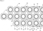
- the laminated stator core 10 according to one embodiment of the present invention is described.
- the laminated stator core 10 according to one embodiment of the present invention comprises: a yoke section 11; pole sections 12 and 13 formed inside the yoke section 11; and a rotor space 14 formed between the pole sections 12 and 13.
- An outline of the yoke section 11 is substantially rectangular shaped when viewed from the top.
- the rotor space 14 is circular shaped when viewed from the top.
- the laminated stator core 10 is rectangular shaped when viewed from the top and four corners thereof are rounded off.
- a plurality of core sheets 15 and 16 having a rectangular shape are sequentially and alternately laminated, and then caulked (interlocked) through caulking portions 17.
- a center 20 of the rotor space 14 is arranged vertically and laterally off-center from each center of the core sheets 15 and 16.
- ⁇ , ⁇ , and ⁇ are set within the following ranges: 0 ⁇ ⁇ ⁇ 0.05a; 0 ⁇ ⁇ ⁇ 0.05a; and 0 ⁇ ⁇ ⁇ 0.05b.
- ⁇ and ⁇ are set to be equal or substantially equal.
- the values of ⁇ , ⁇ , and ⁇ are set to less than 0.05a or 0.05b since ⁇ , ⁇ , and ⁇ greater than 0.05a or 0.05b result in too wide differences between projections and recesses formed along the side surfaces of the laminated stator core 10, which decreases the efficiency in the use of the core sheets.
- a distance from the center 20 of the rotor space 14 to a top side 23 is (a - ⁇ ) / 2
- to a bottom side 24 is (a + ⁇ ) / 2
- to a left-hand side 25 is (b + ⁇ ) / 2
- to a right-hand side 26 is (b - ⁇ ) / 2.
- the core sheets 15 and 16 are congruent.
- the core sheets 15 and 16 are laminated after being rotated (by 180 degrees in this embodiment) around the center 20 of the rotor space 14. This method enables projections and recesses 28 to be formed on the side surfaces of the laminated stator core 10, which is rectangular shaped when viewed from the top and formed by the identically shaped core sheets 15 and 16, thereby improving a cooling ability of the core 10.
- the projecting length of projections and recesses 28 is determined by the values of ⁇ , ⁇ , and ⁇ . In general, the length is preferably set to 0.5 to 4 times the thickness of each core sheet.
- both ends 34 of a magnetic strip 33 are used as the bottom side 19 of the core sheet 15 and the top side 23 of the core sheet 16.
- circular-arc shaped locating portions 31 are provided at the four corners of the core sheets 15, 16 and axisymmetrically located at the same distance (i.e. the same radius) from the center 20 of the rotor space 14. Also, the locating portions 31 serve to round off the four corners of the core sheets 15 and 16.
- the magnetic strip 33 is used that has an enough width to allocate three pieces of the core sheets 15 and 16 in the width direction of the strip 33.
- the both ends (also called sides or side faces) 34 of the strip 33, in unchanged form, are used as one of the sides of the core sheets 15 and 16, and thus the width of the strip 33 is selected to be 3a or slightly smaller than 3a.
- one piece of the strip 33 yields the core sheets 15 and 16 to be lined up uniformly to the feed direction of the strip and aligned in three lines in the width direction of the strip 33.
- a rotor (rotator) and a stator are blanked from the same material strip, so that the blanking of the rotor should be completed before that of the stator.
- pilot holes 35 and 36 are used that are preliminarily formed in the both ends of the strip 33 at the interval of "b" in the feed direction of the strip 33.
- the parts having the pilot holes 35 and 36 are located outside the locating portions 31 of the core sheets 15 and 16, and the parts are blanked eventually.
- a die device (a set of a punch and a die) is set such that the center 20 of the rotor space 14 is positioned: ⁇ /2 forward from the middle point between adjacent pilot holes 35 or 36 in the feed direction of the strip 33; and (a - a)/2 inward from the end of the strip 33.
- a borderline 43 (see FIG 5 ) divides the core sheets 15 and 16 in the end 34 and those in the middle line, and a distance between the borderline 43 and the center of the rotor space 14 of the core sheet 15 or 16 in the end is (a + ⁇ ) / 2.
- a distance between the centers of the rotor spaces 14 is "b" in the feed direction of the strip 33.
- the center 20 of the rotor space 14 of the core sheet 15 or 16 in the middle line should be located (a - ⁇ ) / 2 inward from the borderline 43 in the width direction of the strip 33.
- the three pieces of the core sheets 15 and 16 are aligned in the width direction of the strip 33, and each of the core sheets 15 and 16 has the lateral width of "b" and the vertical width of "a” if ⁇ is equal to ⁇ .
- each of the core sheets 15 and 16 in both ends in the width direction of the strip 33 has the vertical length that is shorter than "a" by ( ⁇ - ⁇ ) / 2.
- the values of ⁇ , ⁇ , and ⁇ determine the formation of the projections and recesses 28 (the height of the projections) on a finished product, that is the laminated stator core 10.
- the strip 33 is fed through a first to an eighth stations (processes) to produce the core sheets 15 and 16.
- the core sheets 15 and 16 are attached to each other and aligned in the feed direction of the strip 33, and then the core sheets 15 and 16 are blanked and pressed into the die.
- a rotor core sheet may be produced from the blanked piece of the rotor space 14.
- slots 39 are punched out, thereby forming a part of pole pieces 37 and 38 inside the core sheets 15 and 16.
- a caulking hole (rectangular through hole) as one example of a caulking portion 17 (V-shaped caulking in this embodiment) is formed in the core sheet 16 being the lowest core sheet.
- the punch does not work for the core sheets 15 and 16 except the lowest core sheet 16, in short, the caulking hole is formed only in the lowest core sheet 16.
- the caulking portions 17 of the well-known V-shaped caulking are formed in the core sheets 15 and 16 except in the lowest core sheet 16.
- slots 40 are punched out, thereby forming the remaining bits of the pole pieces 37 and 38. This process determines the shapes of the pole pieces 37 and 38 formed inside yoke pieces 42.
- slots 41 are punched out, thereby forming the locating portions 31 at the four corners of the core sheets 15 and 16.
- pilot holes 35 and 36 are blanked.
- circular arcs which are formed along the joining sections between the yoke pieces 42 and the pole pieces 37 and 38, are used as new pilot holes.
- Pilot pins 43a as shown in the fourth and subsequent stations of FIG. 4 , determine the position of the strip 33 under processing.
- the slots 41 may be blanked in this station.
- the core sheets 15 and 16 lined up in the top end, as shown in FIG 4 are punched out.
- the core sheets 15 and 16 lined up in the bottom end, as shown in FIG 4 are punched out. Since both of the fifth and sixth stations have the same procedure for blanking the core sheets 15 and 16 and laminating them inside the die, only the sixth station is described in details.
- FIG. 5 illustrates the sixth station and the details of the core sheets 15 and 16 in the bottom end of the strip.
- the explanation is now given regarding the blanking of the lowest core sheet 16.
- the core sheet 16 has the vertical width of "a" approximately ("a + ⁇ / 2 - a / 2" exactly) and the lateral width of "b.”
- the core sheet 16 has the center 20 of the rotor space 14 located (b + ⁇ ) / 2 to the proximal side from the borderline 44 and (a + ⁇ ) / 2 below from the borderline 43.
- the borderline 44 divides the core sheet 16 from the core sheet 15 located at the proximal side of the die device, whereas the borderline 43 divides the core sheet 16 from the core sheet 15 located in the middle line of the strip 33.
- the die device (a cutting tool with a die and a punch) is adjusted to have the vertical width of (a + ⁇ ) and the lateral width of (b + ⁇ ).
- the cutting edge of the die device (one side of the cutting tool) is set along the borderlines 43 and 44, and then the core sheet 16 is blanked and pressed into the die.
- the core sheet 16 is cut off along the borderlines 43 and 44, but a bottom side facing the borderline 43 and a left hand side facing the borderline 44 are not cut off, since the size of the die device is larger than that of the core sheet 16.
- the distances from the center 20 of the rotor space 14 to the bottom side and to the left hand side are (a - ⁇ ) / 2 and (b - ⁇ ) / 2, respectively. Therefore, the die device does not cut off the same ends of the core sheet 16 twice.
- the blanking of the four locating portions 31 is carried out, each of which has a circular arc shape and the same radius from the center 20 of the rotor space.
- the blanked core sheet 16 is pressed into the blank die at the lower part of the die device, and then the core sheet 16 is rotated by 180 degrees. As mentioned above, the caulking portions 17 formed in the lowest core sheet 16 are caulking holes.
- the core sheet 15 to be produced next is exactly the same as the core sheet 16 when the core sheet 15 belongs to the strip 33. Thus, the core sheet 15 is blanked in the same process as the core sheet 16, and the blanked core sheet 15 is laminated on the lowest core sheet 16 and interlocked with each other.
- the rotor spaces 14 and the pole pieces 37, 38 can be vertically aligned with one another.
- the core sheets 15 and 16 are punched out by the same procedure mentioned above.
- 180-degree rotations are performed before being laminated on the core sheets 15.
- the laminated stator core 10 shown in FIGS. 1 to 3 is produced.
- the seventh station is an idle station.
- the core sheets 15 and 16 in the middle line of the strip are punched out.
- the core sheets 15 and 16 in the middle line of the strip as same as those in both ends of the strip, have the centers of rotor spaces 14 arranged eccentrically to the outlines of the core sheets 15 and 16. Therefore, the core sheets 15 and 16 in the middle line of the strip are blanked, rotated by a predetermined angle, and laminated in the same procedures as for those in both ends of the strip to yield the laminate stator core 10. Formed by press works, the outlines of the core sheets 15 and 16 in the middle line of the strip are positioned accurately.
- the die device with a low accuracy blanks the same core sheets twice at the slightly different positions.
- the die device may be designed such that a cutting width of each punch and die is larger than the vertical width of the core sheet 15 or 16, and such that previously-cut top and bottom sides of the core sheet 15 or 16 are placed inside the cutting position of each punch and die.
- the method for manufacturing the core sheets 15 and 16 aligned in the middle line of the strip 33 is applicable to the production of the core sheets 15 and 16 in one line from a strip having a width of "a.”
- the laminated stator core 50 is formed with core sheets 51 and 52, and the core sheets 51 and 52 each have a plurality (multiplicity) of identically shaped pole pieces 53 inside thereof and a rotor space 55 within the pole pieces 53.
- the core sheets 51 have vertically and laterally parallel sides, and every other sheet 51 or every other set of the plural sheets 51 are to be the core sheet(s) 52 by 180-degree rotation and lamination, thereby forming projections and recesses 56 and 57 around the laminated stator core 50.
- the laminated stator core 50 is manufactured in the same way as the above-mentioned laminated stator core 10.
- a strip 58 with rotor spaces blanked is supplied into the die device and slots for forming the pole pieces 53 are punched out.
- locating portions 59 located around the core sheet are punched out, and finally the core sheet is cut off and pressed straight into a die using a punch.
- the cutting edges of punches and dies are adjusted to be larger than open ends of the core sheet 51 to avoid cutting the outlines thereof twice.
- the locating portions 59 in a circular arc shape are formed at the four corners of the core sheet 51 with respect to the center of the rotor space 55.
- Provided at the four corners of the die, which houses the cut out core sheets 51 inside are the sidewalls (positioning walls) for positioning the core sheets 51.
- Every other core sheet 51 becomes the core sheet 52 by 180-degree rotation around the center of the rotor space 55 and lamination.
- the laminated stator core 50 shown in FIG 6 is formed.
- the core sheets 51 and the core sheets 52 which are the core sheets 51 rotated 180 degrees, have the pole pieces 53, the rotor spaces 55, and the caulking portions 17 vertically aligned.
- the present invention is not limited to the above-stated embodiments.
- the present invention may be applied to such a case that one or two lines, or four or more lines of the core sheets are produced from one strip, and the produced core sheets are rotated and laminated inside a blank die.
- the core sheets are formed in four or more lines, the core sheets in adjacent lines are separately punched out in the different stations.
- every group of the core sheets may be rotated before being laminated one on another.
- the core sheets to be laminated are identical in shape, thereby lowering the cost of the die device and simplifying the manufacturing procedures. Therefore, the manufacturing cost of the laminated stator core is reduced.
- the core sheets are rotated, laminated, and interlocked with one another with the rotor spaces thereof vertically aligned to produce the laminated stator core having a uniform height and projections and recesses along the side surfaces of the core, which increases the surface areas of the core. As a result, a cooling ability of the core is improved when it is in use. Therefore, the rotating machines (such as motors) with higher efficiencies can be obtained.
Landscapes
- Engineering & Computer Science (AREA)
- Power Engineering (AREA)
- Mechanical Engineering (AREA)
- Manufacturing & Machinery (AREA)
- Manufacture Of Motors, Generators (AREA)
- Iron Core Of Rotating Electric Machines (AREA)
Claims (5)
- Procédé de fabrication d'un noyau de stator stratifié au moyen d'une partie latérale d'une bande magnétique (33) en tant que côté d'une tôle de noyau (15, 16), la tôle de noyau ayant une forme rectangulaire avec une largeur verticale (a + β / 2 - α / 2) et une largeur latérale "b", la tôle de noyau présentant un espace de rotor (14) rond, formé excentriquement dans la direction latérale et la direction verticale par rapport au centre de la tôle de noyau (15, 16), ledit procédé étant caractérisé par les étapes suivantes :une étape 1 de formation des espaces de rotor (14), les espaces de rotor (14) adjacents dans une direction d'avance de la bande (33) présentant une distance "b" entre leurs centres (20) respectifs, les centres (20) des espaces de rotor (14) des tôles de noyau (15, 16) à l'extrémité dans le sens de la largeur de la bande (33) étant distants de (a - α) / 2 du bord latéral des tôles de noyau (15, 16) vers l'intérieur ;une étape 2 de découpe de fentes (39, 40, 41) dans la bande (33) présentant les espaces de rotor (14), les fentes (39, 40, 41) étant ménagées par rapport au centre (20) de l'espace de rotor (14), des pièces polaires magnétiques (37, 38) étant ainsi formées à l'intérieur de la tôle de noyau (15, 16) et des parties de positionnement en arc de cercle (31) aux coins de la tôle de noyau (15, 16) en symétrie axiale par rapport au centre de l'espace de rotor (14) ; etune étape 3 de découpe de la tôle de noyau (15, 16) au moyen d'un ensemble à poinçon et à matrice, de manière à aligner les axes du poinçon et de la matrice avec le centre (20) de l'espace de rotor (14), le poinçon et la matrice présentant chacun une largeur verticale (a + β) et une largeur latérale (b + γ) ; de pression de la tôle de noyau (15, 16) dans la matrice ; et de stratification de la tôle de noyau (15, 16) à l'intérieur de la matrice, sa mise en place étant réglée au moyen de parois de positionnement ajustées aux parties de positionnement (31) de la tôle de noyau (15, 16) ;la matrice faisant tourner de 180 degrés chaque tôle de noyau (15, 16) ou chaque ensemble de tôles de noyau (15, 16) préalablement à la stratification des tôles de noyau (15, 16) pour former des saillies (28) et des retraits (28) de 0,5 à 4 fois l'épaisseur des tôles de noyau (15, 16) sur les côtés du noyau de stator stratifié, les valeurs de α, β, et γ satisfaisant respectivement aux inégalités 0 < α < 0,05a, 0 < β < 0,05a et 0 < γ < 0,05b.
- Procédé selon la revendication 1, caractérisé en ce que la bande (33) comprend au moins trois lignes de tôles de noyau (15, 16), les tôles de noyau (15, 16) alignées dans le sens de la largeur de la bande (33) étant orientées de la même manière dans la direction d'avance de la bande (33), et chacune des tôles de noyau (15, 16) ayant le centre de l'espace de rotor (14) disposé excentriquement dans une direction dans le sens de la largeur de la bande (33), sur une ligne intérieure entre les tôles de noyau (15, 16) aux deux extrémités de la bande (33).
- Procédé selon la revendication 2, caractérisé en ce que les tôles de noyau (15, 16) de la ligne intérieure sont découpées après découpe des tôles de noyau (15, 16) aux deux extrémités.
- Procédé selon la revendication 3, caractérisé en ce que les tôles de noyau (15, 16) sont alignées sur une pluralité de lignes intérieures et orientées de la même manière dans la direction d'avance de la bande (33), et en ce que les tôles de noyau (15, 16) sont découpées séquentiellement.
- Procédé selon la revendication 2, caractérisé en ce que les tôles de noyau (15, 16) sur la/les ligne(s) intérieure(s) sont découpées, tournées et stratifiées de la même manière que les tôles de noyau (15, 16) aux deux extrémités.
Applications Claiming Priority (2)
| Application Number | Priority Date | Filing Date | Title |
|---|---|---|---|
| JP2007304743 | 2007-11-26 | ||
| PCT/JP2008/070510 WO2009069463A1 (fr) | 2007-11-26 | 2008-11-11 | Noyau de stator stratifié et procédé de fabrication apparenté |
Publications (3)
| Publication Number | Publication Date |
|---|---|
| EP2216882A1 EP2216882A1 (fr) | 2010-08-11 |
| EP2216882A4 EP2216882A4 (fr) | 2013-06-19 |
| EP2216882B1 true EP2216882B1 (fr) | 2017-01-25 |
Family
ID=40678365
Family Applications (1)
| Application Number | Title | Priority Date | Filing Date |
|---|---|---|---|
| EP08855573.5A Not-in-force EP2216882B1 (fr) | 2007-11-26 | 2008-11-11 | Procédé de fabrication d'un noyau de stator feuilleté |
Country Status (5)
| Country | Link |
|---|---|
| US (1) | US8193681B2 (fr) |
| EP (1) | EP2216882B1 (fr) |
| JP (2) | JP4467640B2 (fr) |
| CN (1) | CN101828321B (fr) |
| WO (1) | WO2009069463A1 (fr) |
Families Citing this family (18)
| Publication number | Priority date | Publication date | Assignee | Title |
|---|---|---|---|---|
| JP5854184B2 (ja) | 2010-03-02 | 2016-02-09 | セイコーエプソン株式会社 | 液体噴射ヘッド、液体噴射装置、圧電素子、超音波センサー及び赤外センサー |
| JP5716897B2 (ja) | 2010-03-02 | 2015-05-13 | セイコーエプソン株式会社 | 液体噴射ヘッド、液体噴射装置、圧電素子、超音波センサー及び赤外センサー |
| JP5839157B2 (ja) | 2010-03-02 | 2016-01-06 | セイコーエプソン株式会社 | 液体噴射ヘッド、液体噴射装置、圧電素子、超音波センサー及び赤外センサー |
| JP5854183B2 (ja) | 2010-03-02 | 2016-02-09 | セイコーエプソン株式会社 | 液体噴射ヘッド、液体噴射装置、圧電素子、超音波センサー及び赤外センサー |
| US8850937B2 (en) * | 2011-06-30 | 2014-10-07 | GM Global Technology Operations LLC | Method of manufacturing segmented stator cores |
| JP5726118B2 (ja) * | 2012-03-27 | 2015-05-27 | 三菱電機株式会社 | 積層固定子鉄心、積層固定子鉄心の製造方法 |
| JP5966597B2 (ja) * | 2012-05-16 | 2016-08-10 | マツダ株式会社 | 板金プレス加工方法 |
| JP5469759B1 (ja) * | 2013-03-04 | 2014-04-16 | 株式会社三井ハイテック | 回転子鉄心及びその製造方法 |
| US9065318B2 (en) | 2013-03-14 | 2015-06-23 | Mitsui High-Tec, Inc. | Rotor core and method of manufacturing the same |
| DE102015101390A1 (de) * | 2015-01-30 | 2016-08-04 | Hoerbiger Antriebstechnik Holding Gmbh | Verfahren sowie Vorrichtung zur Herstellung von Reibmomente übertragenden Blechringen |
| KR101808566B1 (ko) * | 2015-05-29 | 2017-12-13 | 니혼 덴산 가부시키가이샤 | 로터 코어의 제조 방법, 로터의 제조 방법, 로터, 및 모터 |
| CN105162270A (zh) * | 2015-10-22 | 2015-12-16 | 珠海凯邦电机制造有限公司 | 一种定子冲片、定子及电机 |
| US10751782B2 (en) * | 2016-01-27 | 2020-08-25 | Mitsui High-Tec, Inc. | Method for processing laminated material |
| JP6797039B2 (ja) | 2017-01-25 | 2020-12-09 | 株式会社三井ハイテック | 積層鉄心の製造方法及び積層鉄心の製造装置 |
| DE102017205847A1 (de) * | 2017-04-06 | 2018-10-11 | Bühler Motor GmbH | Elektronisch kommutierter Gleichstrommotor und Verfahren zur Montage eines elektronisch kommutierten Gleichstrommotors |
| CN107104568B (zh) * | 2017-07-04 | 2023-04-25 | 杭州同孚环保科技有限公司 | 一种对极设置的磁阻电机 |
| JP7137918B2 (ja) * | 2017-10-16 | 2022-09-15 | 株式会社三井ハイテック | 積層鉄心の製造方法 |
| CN113617920B (zh) * | 2021-07-12 | 2023-05-12 | 南通沪达机械设备有限公司 | 一种电机定子冲片加工方法 |
Family Cites Families (22)
| Publication number | Priority date | Publication date | Assignee | Title |
|---|---|---|---|---|
| JPS50146805A (fr) * | 1974-05-15 | 1975-11-25 | ||
| DD135972A3 (de) * | 1976-05-14 | 1979-06-13 | Zaumseil Hans Juergen | Verfahren und schneidwerkzeug zur herstellung von elektromotorenblechen |
| JPS53145101U (fr) * | 1977-04-22 | 1978-11-15 | ||
| JPS6016183B2 (ja) * | 1977-12-14 | 1985-04-24 | 株式会社日立製作所 | 回転電機の固定子鉄心の製造方法 |
| JPH0612936B2 (ja) | 1983-12-01 | 1994-02-16 | 株式会社日立製作所 | 電動機用固定子鉄心の製造方法 |
| JPS6132753U (ja) | 1984-07-26 | 1986-02-27 | 三菱電機株式会社 | 直流機 |
| US4616151A (en) * | 1984-12-07 | 1986-10-07 | General Motors Corporation | Armature with quiet core construction |
| FR2583593B1 (fr) | 1985-06-18 | 1989-06-16 | Dso Elprom | Stator feuillete a ailettes pour une machine electrique. |
| JPS6212342A (ja) * | 1985-07-08 | 1987-01-21 | ダルヤフノ・ストパンスコ・オベデイネニエ“エルプロム” | フインを有する固定子積重体 |
| JPS62114449A (ja) | 1985-11-13 | 1987-05-26 | Sanyo Electric Co Ltd | 電動機鉄心 |
| US4642502A (en) * | 1986-04-24 | 1987-02-10 | General Motors Corporation | Dynamoelectric machine with permanent magnet and magnet mounting surface arrangement |
| JP2556776B2 (ja) | 1991-06-26 | 1996-11-20 | 株式会社三井ハイテック | 電動機の固定子用積層鉄心の製造方法 |
| US5331238A (en) * | 1993-03-01 | 1994-07-19 | Sundstrand Corporation | Apparatus for containment and cooling of a core within a housing |
| JP3585130B2 (ja) * | 1993-09-24 | 2004-11-04 | オリエンタルモーター株式会社 | リニアパルスモータ |
| JPH08331780A (ja) * | 1995-05-31 | 1996-12-13 | Hitachi Ltd | 小形インダクションモータ |
| JPH09121519A (ja) * | 1995-10-27 | 1997-05-06 | Sawafuji Electric Co Ltd | 発電機 |
| US6349463B1 (en) * | 1999-09-30 | 2002-02-26 | Reliance Electric Technologies, Llc | Method of making an electric motor stator assembly |
| JP2001103691A (ja) * | 1999-09-30 | 2001-04-13 | Densei Lambda Kk | ステータコア及び電動機 |
| JP4018885B2 (ja) * | 2001-05-25 | 2007-12-05 | 株式会社三井ハイテック | 積層鉄心 |
| JP3687749B2 (ja) * | 2003-04-23 | 2005-08-24 | 株式会社三井ハイテック | スキュー形状可変型積層鉄心及びその製造方法 |
| CN1294685C (zh) * | 2003-07-29 | 2007-01-10 | 发那科株式会社 | 电机及电机制造装置 |
| JP4498154B2 (ja) * | 2005-01-27 | 2010-07-07 | ファナック株式会社 | モータの製造方法、及びモータ製造装置 |
-
2008
- 2008-11-11 WO PCT/JP2008/070510 patent/WO2009069463A1/fr active Application Filing
- 2008-11-11 CN CN200880111683.0A patent/CN101828321B/zh not_active Expired - Fee Related
- 2008-11-11 JP JP2009506843A patent/JP4467640B2/ja active Active
- 2008-11-11 EP EP08855573.5A patent/EP2216882B1/fr not_active Not-in-force
- 2008-11-11 US US12/667,811 patent/US8193681B2/en not_active Expired - Fee Related
-
2009
- 2009-11-20 JP JP2009265249A patent/JP2010045973A/ja active Pending
Non-Patent Citations (1)
| Title |
|---|
| None * |
Also Published As
| Publication number | Publication date |
|---|---|
| CN101828321A (zh) | 2010-09-08 |
| US20100327690A1 (en) | 2010-12-30 |
| EP2216882A1 (fr) | 2010-08-11 |
| JPWO2009069463A1 (ja) | 2011-04-14 |
| CN101828321B (zh) | 2012-11-28 |
| US8193681B2 (en) | 2012-06-05 |
| JP2010045973A (ja) | 2010-02-25 |
| EP2216882A4 (fr) | 2013-06-19 |
| WO2009069463A1 (fr) | 2009-06-04 |
| JP4467640B2 (ja) | 2010-05-26 |
Similar Documents
| Publication | Publication Date | Title |
|---|---|---|
| EP2216882B1 (fr) | Procédé de fabrication d'un noyau de stator feuilleté | |
| CN102111042B (zh) | 层叠铁心的制造方法 | |
| US9225228B2 (en) | Method of manufacturing laminated stator core and laminated stator core manufactured by the method | |
| EP1391975A1 (fr) | Noyau feuillete et procede de production dudit noyau | |
| US8456057B2 (en) | Laminated stator core | |
| US9099897B2 (en) | Method for connecting end sections of an annular laminated article and articles made therefrom | |
| JP5379522B2 (ja) | 分割鉄心片の製造方法 | |
| EP2445086B1 (fr) | Noyau de stator et procédé de fabrication de ce noyau | |
| JP3103343B2 (ja) | 固定子用積層磁極鉄心の製造方法及び同製造方法に用いる金型装置 | |
| JP3722539B2 (ja) | 環状積層鉄心の製造方法及び順送り金型装置 | |
| CN101860134A (zh) | 风力发电机定转子冲片冲压加工工艺 | |
| US9065318B2 (en) | Rotor core and method of manufacturing the same | |
| CN105471196B (zh) | 叠片铁芯的制造方法及制造装置 | |
| JP2010045921A (ja) | 積層鉄心の製造装置および製造方法 | |
| US8082654B2 (en) | Production method for large rotor/stator laminations | |
| CN101719705B (zh) | 旋转电机定子铁芯片的定向冲剪加工方法 | |
| JP2006026662A (ja) | 分割積層コアの製造方法と製造用順送り金型 | |
| KR20010042934A (ko) | 박판 금속 절삭 부품으로부터 전기 기계의 회전자나고정자를 제조하기 위한 방법 | |
| JP5291774B2 (ja) | 積層鉄心の製造方法及び製造装置 | |
| KR101881257B1 (ko) | 적층코아 및, 그 제조방법 | |
| GB2268433A (en) | Method of punching interlocking parts for stators | |
| JP4912088B2 (ja) | 積層鉄心の製造方法および製造装置 | |
| JP6400458B2 (ja) | 打抜き方法及び積層鉄心の製造方法 | |
| US11141776B2 (en) | Method of manufacturing washers | |
| CN114785008B (zh) | 一种设有斜槽的定子铁芯及加工方法 |
Legal Events
| Date | Code | Title | Description |
|---|---|---|---|
| PUAI | Public reference made under article 153(3) epc to a published international application that has entered the european phase |
Free format text: ORIGINAL CODE: 0009012 |
|
| 17P | Request for examination filed |
Effective date: 20100330 |
|
| AK | Designated contracting states |
Kind code of ref document: A1 Designated state(s): AT BE BG CH CY CZ DE DK EE ES FI FR GB GR HR HU IE IS IT LI LT LU LV MC MT NL NO PL PT RO SE SI SK TR |
|
| AX | Request for extension of the european patent |
Extension state: AL BA MK RS |
|
| DAX | Request for extension of the european patent (deleted) | ||
| A4 | Supplementary search report drawn up and despatched |
Effective date: 20130516 |
|
| RIC1 | Information provided on ipc code assigned before grant |
Ipc: H02K 5/18 20060101ALN20130510BHEP Ipc: H02K 1/16 20060101ALI20130510BHEP Ipc: B21D 43/02 20060101ALI20130510BHEP Ipc: B21D 28/06 20060101ALI20130510BHEP Ipc: H02K 1/14 20060101AFI20130510BHEP Ipc: H02K 15/02 20060101ALI20130510BHEP |
|
| 17Q | First examination report despatched |
Effective date: 20150528 |
|
| REG | Reference to a national code |
Ref country code: DE Ref legal event code: R079 Ref document number: 602008048608 Country of ref document: DE Free format text: PREVIOUS MAIN CLASS: H02K0001180000 Ipc: H02K0001140000 |
|
| GRAP | Despatch of communication of intention to grant a patent |
Free format text: ORIGINAL CODE: EPIDOSNIGR1 |
|
| RIC1 | Information provided on ipc code assigned before grant |
Ipc: B21D 43/02 20060101ALI20160718BHEP Ipc: H02K 15/02 20060101ALI20160718BHEP Ipc: H02K 1/14 20060101AFI20160718BHEP Ipc: B21D 28/06 20060101ALI20160718BHEP Ipc: H02K 5/18 20060101ALN20160718BHEP Ipc: H02K 1/16 20060101ALI20160718BHEP |
|
| RIC1 | Information provided on ipc code assigned before grant |
Ipc: H02K 15/02 20060101ALI20160726BHEP Ipc: B21D 43/02 20060101ALI20160726BHEP Ipc: H02K 1/16 20060101ALI20160726BHEP Ipc: H02K 5/18 20060101ALN20160726BHEP Ipc: H02K 1/14 20060101AFI20160726BHEP Ipc: B21D 28/06 20060101ALI20160726BHEP |
|
| INTG | Intention to grant announced |
Effective date: 20160808 |
|
| GRAS | Grant fee paid |
Free format text: ORIGINAL CODE: EPIDOSNIGR3 |
|
| GRAA | (expected) grant |
Free format text: ORIGINAL CODE: 0009210 |
|
| AK | Designated contracting states |
Kind code of ref document: B1 Designated state(s): AT BE BG CH CY CZ DE DK EE ES FI FR GB GR HR HU IE IS IT LI LT LU LV MC MT NL NO PL PT RO SE SI SK TR |
|
| REG | Reference to a national code |
Ref country code: GB Ref legal event code: FG4D |
|
| REG | Reference to a national code |
Ref country code: CH Ref legal event code: EP |
|
| REG | Reference to a national code |
Ref country code: AT Ref legal event code: REF Ref document number: 864628 Country of ref document: AT Kind code of ref document: T Effective date: 20170215 |
|
| REG | Reference to a national code |
Ref country code: IE Ref legal event code: FG4D |
|
| REG | Reference to a national code |
Ref country code: DE Ref legal event code: R096 Ref document number: 602008048608 Country of ref document: DE |
|
| REG | Reference to a national code |
Ref country code: LT Ref legal event code: MG4D |
|
| REG | Reference to a national code |
Ref country code: NL Ref legal event code: MP Effective date: 20170125 |
|
| REG | Reference to a national code |
Ref country code: AT Ref legal event code: MK05 Ref document number: 864628 Country of ref document: AT Kind code of ref document: T Effective date: 20170125 |
|
| PG25 | Lapsed in a contracting state [announced via postgrant information from national office to epo] |
Ref country code: NL Free format text: LAPSE BECAUSE OF FAILURE TO SUBMIT A TRANSLATION OF THE DESCRIPTION OR TO PAY THE FEE WITHIN THE PRESCRIBED TIME-LIMIT Effective date: 20170125 |
|
| PG25 | Lapsed in a contracting state [announced via postgrant information from national office to epo] |
Ref country code: FI Free format text: LAPSE BECAUSE OF FAILURE TO SUBMIT A TRANSLATION OF THE DESCRIPTION OR TO PAY THE FEE WITHIN THE PRESCRIBED TIME-LIMIT Effective date: 20170125 Ref country code: HR Free format text: LAPSE BECAUSE OF FAILURE TO SUBMIT A TRANSLATION OF THE DESCRIPTION OR TO PAY THE FEE WITHIN THE PRESCRIBED TIME-LIMIT Effective date: 20170125 Ref country code: GR Free format text: LAPSE BECAUSE OF FAILURE TO SUBMIT A TRANSLATION OF THE DESCRIPTION OR TO PAY THE FEE WITHIN THE PRESCRIBED TIME-LIMIT Effective date: 20170426 Ref country code: IS Free format text: LAPSE BECAUSE OF FAILURE TO SUBMIT A TRANSLATION OF THE DESCRIPTION OR TO PAY THE FEE WITHIN THE PRESCRIBED TIME-LIMIT Effective date: 20170525 Ref country code: NO Free format text: LAPSE BECAUSE OF FAILURE TO SUBMIT A TRANSLATION OF THE DESCRIPTION OR TO PAY THE FEE WITHIN THE PRESCRIBED TIME-LIMIT Effective date: 20170425 Ref country code: LT Free format text: LAPSE BECAUSE OF FAILURE TO SUBMIT A TRANSLATION OF THE DESCRIPTION OR TO PAY THE FEE WITHIN THE PRESCRIBED TIME-LIMIT Effective date: 20170125 |
|
| PG25 | Lapsed in a contracting state [announced via postgrant information from national office to epo] |
Ref country code: PL Free format text: LAPSE BECAUSE OF FAILURE TO SUBMIT A TRANSLATION OF THE DESCRIPTION OR TO PAY THE FEE WITHIN THE PRESCRIBED TIME-LIMIT Effective date: 20170125 Ref country code: ES Free format text: LAPSE BECAUSE OF FAILURE TO SUBMIT A TRANSLATION OF THE DESCRIPTION OR TO PAY THE FEE WITHIN THE PRESCRIBED TIME-LIMIT Effective date: 20170125 Ref country code: BG Free format text: LAPSE BECAUSE OF FAILURE TO SUBMIT A TRANSLATION OF THE DESCRIPTION OR TO PAY THE FEE WITHIN THE PRESCRIBED TIME-LIMIT Effective date: 20170425 Ref country code: LV Free format text: LAPSE BECAUSE OF FAILURE TO SUBMIT A TRANSLATION OF THE DESCRIPTION OR TO PAY THE FEE WITHIN THE PRESCRIBED TIME-LIMIT Effective date: 20170125 Ref country code: SE Free format text: LAPSE BECAUSE OF FAILURE TO SUBMIT A TRANSLATION OF THE DESCRIPTION OR TO PAY THE FEE WITHIN THE PRESCRIBED TIME-LIMIT Effective date: 20170125 Ref country code: PT Free format text: LAPSE BECAUSE OF FAILURE TO SUBMIT A TRANSLATION OF THE DESCRIPTION OR TO PAY THE FEE WITHIN THE PRESCRIBED TIME-LIMIT Effective date: 20170525 Ref country code: AT Free format text: LAPSE BECAUSE OF FAILURE TO SUBMIT A TRANSLATION OF THE DESCRIPTION OR TO PAY THE FEE WITHIN THE PRESCRIBED TIME-LIMIT Effective date: 20170125 |
|
| REG | Reference to a national code |
Ref country code: DE Ref legal event code: R097 Ref document number: 602008048608 Country of ref document: DE |
|
| PG25 | Lapsed in a contracting state [announced via postgrant information from national office to epo] |
Ref country code: EE Free format text: LAPSE BECAUSE OF FAILURE TO SUBMIT A TRANSLATION OF THE DESCRIPTION OR TO PAY THE FEE WITHIN THE PRESCRIBED TIME-LIMIT Effective date: 20170125 Ref country code: IT Free format text: LAPSE BECAUSE OF FAILURE TO SUBMIT A TRANSLATION OF THE DESCRIPTION OR TO PAY THE FEE WITHIN THE PRESCRIBED TIME-LIMIT Effective date: 20170125 Ref country code: SK Free format text: LAPSE BECAUSE OF FAILURE TO SUBMIT A TRANSLATION OF THE DESCRIPTION OR TO PAY THE FEE WITHIN THE PRESCRIBED TIME-LIMIT Effective date: 20170125 Ref country code: RO Free format text: LAPSE BECAUSE OF FAILURE TO SUBMIT A TRANSLATION OF THE DESCRIPTION OR TO PAY THE FEE WITHIN THE PRESCRIBED TIME-LIMIT Effective date: 20170125 Ref country code: CZ Free format text: LAPSE BECAUSE OF FAILURE TO SUBMIT A TRANSLATION OF THE DESCRIPTION OR TO PAY THE FEE WITHIN THE PRESCRIBED TIME-LIMIT Effective date: 20170125 |
|
| PG25 | Lapsed in a contracting state [announced via postgrant information from national office to epo] |
Ref country code: DK Free format text: LAPSE BECAUSE OF FAILURE TO SUBMIT A TRANSLATION OF THE DESCRIPTION OR TO PAY THE FEE WITHIN THE PRESCRIBED TIME-LIMIT Effective date: 20170125 |
|
| PLBE | No opposition filed within time limit |
Free format text: ORIGINAL CODE: 0009261 |
|
| STAA | Information on the status of an ep patent application or granted ep patent |
Free format text: STATUS: NO OPPOSITION FILED WITHIN TIME LIMIT |
|
| 26N | No opposition filed |
Effective date: 20171026 |
|
| PG25 | Lapsed in a contracting state [announced via postgrant information from national office to epo] |
Ref country code: SI Free format text: LAPSE BECAUSE OF FAILURE TO SUBMIT A TRANSLATION OF THE DESCRIPTION OR TO PAY THE FEE WITHIN THE PRESCRIBED TIME-LIMIT Effective date: 20170125 |
|
| REG | Reference to a national code |
Ref country code: DE Ref legal event code: R119 Ref document number: 602008048608 Country of ref document: DE |
|
| PG25 | Lapsed in a contracting state [announced via postgrant information from national office to epo] |
Ref country code: MC Free format text: LAPSE BECAUSE OF FAILURE TO SUBMIT A TRANSLATION OF THE DESCRIPTION OR TO PAY THE FEE WITHIN THE PRESCRIBED TIME-LIMIT Effective date: 20170125 |
|
| GBPC | Gb: european patent ceased through non-payment of renewal fee |
Effective date: 20171111 |
|
| PG25 | Lapsed in a contracting state [announced via postgrant information from national office to epo] |
Ref country code: LI Free format text: LAPSE BECAUSE OF NON-PAYMENT OF DUE FEES Effective date: 20171130 Ref country code: CH Free format text: LAPSE BECAUSE OF NON-PAYMENT OF DUE FEES Effective date: 20171130 |
|
| PG25 | Lapsed in a contracting state [announced via postgrant information from national office to epo] |
Ref country code: LU Free format text: LAPSE BECAUSE OF NON-PAYMENT OF DUE FEES Effective date: 20171111 |
|
| REG | Reference to a national code |
Ref country code: FR Ref legal event code: ST Effective date: 20180731 Ref country code: BE Ref legal event code: MM Effective date: 20171130 |
|
| REG | Reference to a national code |
Ref country code: IE Ref legal event code: MM4A |
|
| PG25 | Lapsed in a contracting state [announced via postgrant information from national office to epo] |
Ref country code: MT Free format text: LAPSE BECAUSE OF NON-PAYMENT OF DUE FEES Effective date: 20171111 |
|
| PG25 | Lapsed in a contracting state [announced via postgrant information from national office to epo] |
Ref country code: DE Free format text: LAPSE BECAUSE OF NON-PAYMENT OF DUE FEES Effective date: 20180602 Ref country code: IE Free format text: LAPSE BECAUSE OF NON-PAYMENT OF DUE FEES Effective date: 20171111 Ref country code: FR Free format text: LAPSE BECAUSE OF NON-PAYMENT OF DUE FEES Effective date: 20171130 |
|
| PG25 | Lapsed in a contracting state [announced via postgrant information from national office to epo] |
Ref country code: GB Free format text: LAPSE BECAUSE OF NON-PAYMENT OF DUE FEES Effective date: 20171111 Ref country code: BE Free format text: LAPSE BECAUSE OF NON-PAYMENT OF DUE FEES Effective date: 20171130 |
|
| PG25 | Lapsed in a contracting state [announced via postgrant information from national office to epo] |
Ref country code: HU Free format text: LAPSE BECAUSE OF FAILURE TO SUBMIT A TRANSLATION OF THE DESCRIPTION OR TO PAY THE FEE WITHIN THE PRESCRIBED TIME-LIMIT; INVALID AB INITIO Effective date: 20081111 |
|
| PG25 | Lapsed in a contracting state [announced via postgrant information from national office to epo] |
Ref country code: CY Free format text: LAPSE BECAUSE OF NON-PAYMENT OF DUE FEES Effective date: 20170125 |
|
| PG25 | Lapsed in a contracting state [announced via postgrant information from national office to epo] |
Ref country code: TR Free format text: LAPSE BECAUSE OF FAILURE TO SUBMIT A TRANSLATION OF THE DESCRIPTION OR TO PAY THE FEE WITHIN THE PRESCRIBED TIME-LIMIT Effective date: 20170125 |