EP2213594B1 - Vorrichtung zum Transportieren von Gegenständen mit einer Profilierung, insbesondere von Flaschen oder Vorformelingen - Google Patents
Vorrichtung zum Transportieren von Gegenständen mit einer Profilierung, insbesondere von Flaschen oder Vorformelingen Download PDFInfo
- Publication number
- EP2213594B1 EP2213594B1 EP10001941.3A EP10001941A EP2213594B1 EP 2213594 B1 EP2213594 B1 EP 2213594B1 EP 10001941 A EP10001941 A EP 10001941A EP 2213594 B1 EP2213594 B1 EP 2213594B1
- Authority
- EP
- European Patent Office
- Prior art keywords
- preforms
- objects
- transport
- housing
- rollers
- Prior art date
- Legal status (The legal status is an assumption and is not a legal conclusion. Google has not performed a legal analysis and makes no representation as to the accuracy of the status listed.)
- Not-in-force
Links
- 210000002105 tongue Anatomy 0.000 claims description 4
- 239000011295 pitch Substances 0.000 description 4
- 238000000071 blow moulding Methods 0.000 description 3
- 230000003247 decreasing effect Effects 0.000 description 2
- 238000001746 injection moulding Methods 0.000 description 2
- 230000007423 decrease Effects 0.000 description 1
- 238000001514 detection method Methods 0.000 description 1
- 230000000694 effects Effects 0.000 description 1
- 238000005516 engineering process Methods 0.000 description 1
- 230000003993 interaction Effects 0.000 description 1
- 239000002184 metal Substances 0.000 description 1
- 238000004806 packaging method and process Methods 0.000 description 1
- 239000000243 solution Substances 0.000 description 1
Images





Classifications
-
- B—PERFORMING OPERATIONS; TRANSPORTING
- B65—CONVEYING; PACKING; STORING; HANDLING THIN OR FILAMENTARY MATERIAL
- B65G—TRANSPORT OR STORAGE DEVICES, e.g. CONVEYORS FOR LOADING OR TIPPING, SHOP CONVEYOR SYSTEMS OR PNEUMATIC TUBE CONVEYORS
- B65G19/00—Conveyors comprising an impeller or a series of impellers carried by an endless traction element and arranged to move articles or materials over a supporting surface or underlying material, e.g. endless scraper conveyors
- B65G19/02—Conveyors comprising an impeller or a series of impellers carried by an endless traction element and arranged to move articles or materials over a supporting surface or underlying material, e.g. endless scraper conveyors for articles, e.g. for containers
- B65G19/025—Conveyors comprising an impeller or a series of impellers carried by an endless traction element and arranged to move articles or materials over a supporting surface or underlying material, e.g. endless scraper conveyors for articles, e.g. for containers for suspended articles
-
- B—PERFORMING OPERATIONS; TRANSPORTING
- B29—WORKING OF PLASTICS; WORKING OF SUBSTANCES IN A PLASTIC STATE IN GENERAL
- B29C—SHAPING OR JOINING OF PLASTICS; SHAPING OF MATERIAL IN A PLASTIC STATE, NOT OTHERWISE PROVIDED FOR; AFTER-TREATMENT OF THE SHAPED PRODUCTS, e.g. REPAIRING
- B29C49/00—Blow-moulding, i.e. blowing a preform or parison to a desired shape within a mould; Apparatus therefor
- B29C49/42—Component parts, details or accessories; Auxiliary operations
- B29C49/4205—Handling means, e.g. transfer, loading or discharging means
- B29C49/42073—Grippers
-
- B—PERFORMING OPERATIONS; TRANSPORTING
- B29—WORKING OF PLASTICS; WORKING OF SUBSTANCES IN A PLASTIC STATE IN GENERAL
- B29C—SHAPING OR JOINING OF PLASTICS; SHAPING OF MATERIAL IN A PLASTIC STATE, NOT OTHERWISE PROVIDED FOR; AFTER-TREATMENT OF THE SHAPED PRODUCTS, e.g. REPAIRING
- B29C49/00—Blow-moulding, i.e. blowing a preform or parison to a desired shape within a mould; Apparatus therefor
- B29C49/42—Component parts, details or accessories; Auxiliary operations
- B29C49/4205—Handling means, e.g. transfer, loading or discharging means
- B29C49/42093—Transporting apparatus, e.g. slides, wheels or conveyors
- B29C49/42101—Conveyors, e.g. flat conveyor or clamping between two bands
-
- B—PERFORMING OPERATIONS; TRANSPORTING
- B65—CONVEYING; PACKING; STORING; HANDLING THIN OR FILAMENTARY MATERIAL
- B65G—TRANSPORT OR STORAGE DEVICES, e.g. CONVEYORS FOR LOADING OR TIPPING, SHOP CONVEYOR SYSTEMS OR PNEUMATIC TUBE CONVEYORS
- B65G15/00—Conveyors having endless load-conveying surfaces, i.e. belts and like continuous members, to which tractive effort is transmitted by means other than endless driving elements of similar configuration
- B65G15/10—Conveyors having endless load-conveying surfaces, i.e. belts and like continuous members, to which tractive effort is transmitted by means other than endless driving elements of similar configuration comprising two or more co-operating endless surfaces with parallel longitudinal axes, or a multiplicity of parallel elements, e.g. ropes defining an endless surface
- B65G15/12—Conveyors having endless load-conveying surfaces, i.e. belts and like continuous members, to which tractive effort is transmitted by means other than endless driving elements of similar configuration comprising two or more co-operating endless surfaces with parallel longitudinal axes, or a multiplicity of parallel elements, e.g. ropes defining an endless surface with two or more endless belts
- B65G15/14—Conveyors having endless load-conveying surfaces, i.e. belts and like continuous members, to which tractive effort is transmitted by means other than endless driving elements of similar configuration comprising two or more co-operating endless surfaces with parallel longitudinal axes, or a multiplicity of parallel elements, e.g. ropes defining an endless surface with two or more endless belts the load being conveyed between the belts
-
- B—PERFORMING OPERATIONS; TRANSPORTING
- B29—WORKING OF PLASTICS; WORKING OF SUBSTANCES IN A PLASTIC STATE IN GENERAL
- B29C—SHAPING OR JOINING OF PLASTICS; SHAPING OF MATERIAL IN A PLASTIC STATE, NOT OTHERWISE PROVIDED FOR; AFTER-TREATMENT OF THE SHAPED PRODUCTS, e.g. REPAIRING
- B29C2949/00—Indexing scheme relating to blow-moulding
- B29C2949/07—Preforms or parisons characterised by their configuration
- B29C2949/0715—Preforms or parisons characterised by their configuration the preform having one end closed
-
- B—PERFORMING OPERATIONS; TRANSPORTING
- B29—WORKING OF PLASTICS; WORKING OF SUBSTANCES IN A PLASTIC STATE IN GENERAL
- B29C—SHAPING OR JOINING OF PLASTICS; SHAPING OF MATERIAL IN A PLASTIC STATE, NOT OTHERWISE PROVIDED FOR; AFTER-TREATMENT OF THE SHAPED PRODUCTS, e.g. REPAIRING
- B29C2949/00—Indexing scheme relating to blow-moulding
- B29C2949/20—Preforms or parisons whereby a specific part is made of only one component, e.g. only one layer
- B29C2949/22—Preforms or parisons whereby a specific part is made of only one component, e.g. only one layer at neck portion
-
- B—PERFORMING OPERATIONS; TRANSPORTING
- B29—WORKING OF PLASTICS; WORKING OF SUBSTANCES IN A PLASTIC STATE IN GENERAL
- B29C—SHAPING OR JOINING OF PLASTICS; SHAPING OF MATERIAL IN A PLASTIC STATE, NOT OTHERWISE PROVIDED FOR; AFTER-TREATMENT OF THE SHAPED PRODUCTS, e.g. REPAIRING
- B29C2949/00—Indexing scheme relating to blow-moulding
- B29C2949/20—Preforms or parisons whereby a specific part is made of only one component, e.g. only one layer
- B29C2949/24—Preforms or parisons whereby a specific part is made of only one component, e.g. only one layer at flange portion
-
- B—PERFORMING OPERATIONS; TRANSPORTING
- B29—WORKING OF PLASTICS; WORKING OF SUBSTANCES IN A PLASTIC STATE IN GENERAL
- B29C—SHAPING OR JOINING OF PLASTICS; SHAPING OF MATERIAL IN A PLASTIC STATE, NOT OTHERWISE PROVIDED FOR; AFTER-TREATMENT OF THE SHAPED PRODUCTS, e.g. REPAIRING
- B29C2949/00—Indexing scheme relating to blow-moulding
- B29C2949/20—Preforms or parisons whereby a specific part is made of only one component, e.g. only one layer
- B29C2949/26—Preforms or parisons whereby a specific part is made of only one component, e.g. only one layer at body portion
-
- B—PERFORMING OPERATIONS; TRANSPORTING
- B29—WORKING OF PLASTICS; WORKING OF SUBSTANCES IN A PLASTIC STATE IN GENERAL
- B29C—SHAPING OR JOINING OF PLASTICS; SHAPING OF MATERIAL IN A PLASTIC STATE, NOT OTHERWISE PROVIDED FOR; AFTER-TREATMENT OF THE SHAPED PRODUCTS, e.g. REPAIRING
- B29C2949/00—Indexing scheme relating to blow-moulding
- B29C2949/20—Preforms or parisons whereby a specific part is made of only one component, e.g. only one layer
- B29C2949/28—Preforms or parisons whereby a specific part is made of only one component, e.g. only one layer at bottom portion
-
- B—PERFORMING OPERATIONS; TRANSPORTING
- B29—WORKING OF PLASTICS; WORKING OF SUBSTANCES IN A PLASTIC STATE IN GENERAL
- B29C—SHAPING OR JOINING OF PLASTICS; SHAPING OF MATERIAL IN A PLASTIC STATE, NOT OTHERWISE PROVIDED FOR; AFTER-TREATMENT OF THE SHAPED PRODUCTS, e.g. REPAIRING
- B29C2949/00—Indexing scheme relating to blow-moulding
- B29C2949/30—Preforms or parisons made of several components
- B29C2949/3024—Preforms or parisons made of several components characterised by the number of components or by the manufacturing technique
-
- B—PERFORMING OPERATIONS; TRANSPORTING
- B29—WORKING OF PLASTICS; WORKING OF SUBSTANCES IN A PLASTIC STATE IN GENERAL
- B29C—SHAPING OR JOINING OF PLASTICS; SHAPING OF MATERIAL IN A PLASTIC STATE, NOT OTHERWISE PROVIDED FOR; AFTER-TREATMENT OF THE SHAPED PRODUCTS, e.g. REPAIRING
- B29C2949/00—Indexing scheme relating to blow-moulding
- B29C2949/30—Preforms or parisons made of several components
- B29C2949/3032—Preforms or parisons made of several components having components being injected
-
- B—PERFORMING OPERATIONS; TRANSPORTING
- B29—WORKING OF PLASTICS; WORKING OF SUBSTANCES IN A PLASTIC STATE IN GENERAL
- B29C—SHAPING OR JOINING OF PLASTICS; SHAPING OF MATERIAL IN A PLASTIC STATE, NOT OTHERWISE PROVIDED FOR; AFTER-TREATMENT OF THE SHAPED PRODUCTS, e.g. REPAIRING
- B29C49/00—Blow-moulding, i.e. blowing a preform or parison to a desired shape within a mould; Apparatus therefor
- B29C49/02—Combined blow-moulding and manufacture of the preform or the parison
- B29C49/06—Injection blow-moulding
-
- B—PERFORMING OPERATIONS; TRANSPORTING
- B29—WORKING OF PLASTICS; WORKING OF SUBSTANCES IN A PLASTIC STATE IN GENERAL
- B29C—SHAPING OR JOINING OF PLASTICS; SHAPING OF MATERIAL IN A PLASTIC STATE, NOT OTHERWISE PROVIDED FOR; AFTER-TREATMENT OF THE SHAPED PRODUCTS, e.g. REPAIRING
- B29C49/00—Blow-moulding, i.e. blowing a preform or parison to a desired shape within a mould; Apparatus therefor
- B29C49/42—Component parts, details or accessories; Auxiliary operations
- B29C49/4205—Handling means, e.g. transfer, loading or discharging means
- B29C49/42069—Means explicitly adapted for transporting blown article
-
- B—PERFORMING OPERATIONS; TRANSPORTING
- B29—WORKING OF PLASTICS; WORKING OF SUBSTANCES IN A PLASTIC STATE IN GENERAL
- B29C—SHAPING OR JOINING OF PLASTICS; SHAPING OF MATERIAL IN A PLASTIC STATE, NOT OTHERWISE PROVIDED FOR; AFTER-TREATMENT OF THE SHAPED PRODUCTS, e.g. REPAIRING
- B29C49/00—Blow-moulding, i.e. blowing a preform or parison to a desired shape within a mould; Apparatus therefor
- B29C49/42—Component parts, details or accessories; Auxiliary operations
- B29C49/4205—Handling means, e.g. transfer, loading or discharging means
- B29C49/42073—Grippers
- B29C49/42087—Grippers holding outside the neck
-
- B—PERFORMING OPERATIONS; TRANSPORTING
- B65—CONVEYING; PACKING; STORING; HANDLING THIN OR FILAMENTARY MATERIAL
- B65G—TRANSPORT OR STORAGE DEVICES, e.g. CONVEYORS FOR LOADING OR TIPPING, SHOP CONVEYOR SYSTEMS OR PNEUMATIC TUBE CONVEYORS
- B65G2201/00—Indexing codes relating to handling devices, e.g. conveyors, characterised by the type of product or load being conveyed or handled
- B65G2201/02—Articles
- B65G2201/0235—Containers
- B65G2201/0244—Bottles
- B65G2201/0247—Suspended bottles
Definitions
- the invention relates to a device for transporting objects according to the preamble of claim 1.
- preforms which are produced in an injection molding machine and then inflated in a blow-molding device into a bottle.
- These preforms have an annular collar which essentially serves to handle the preforms and later bottles.
- the ring collar is provided near the bottom of the bottle opening and usually also limits the thread for screwing a screw cap.
- the preforms produced in the injection molding tool are arranged in complicated and much space-demanding systems and transported to the blow molding. It is new to separate these preforms in a centrifuge-like separator, as he is for example in the WO 2006/084831 A1 is described.
- a bottle conveyor in which the neck of a bottle is located within a two-part housing and is laterally supported by a ring collar in a housing slot. Similar things can be found in the WO 97/10163 A1 ,
- a generic device for transporting bottles with a ring collar by means of a transport device between two slip planes on which the annular collar rests known, the device having a housing slot having a housing, wherein the housing is composed of two housing shells and wherein the Edge edges of the housing slot have the sliding plane.
- Object of the present invention is to provide a suitable device of the type mentioned above, with which the objects, especially the preforms, ordered and safely transported from one to the next station.
- the slideways are part of a housing, which preferably consists of two housing shells.
- the two housing shells form a slot in the region of the slideways, edge edges keeping a desired distance from one another.
- the marginal edges take in the position of use between the preforms.
- the two housing shells should be slidable into one another, for which purpose, for example, overlap two leg strips of the housing shells and can be connected so overlapping each other.
- the containers that are transported preferably have a hull, an annular collar, and an orifice, and are preferably PET bottles or PET preforms.
- the slideways and transport means are provided, the slideways are preferably mounted stationary.
- the slideways can be formed, for example, of plastic or metal strips. But the slides can not only be designed as a bar, but is a Any configuration, such as in the manner of a provided with a circular cross-section band possible.
- the at least one transport device is preferably responsible for the main energy input into the container for forward movement in the transport direction.
- the slideways and the transport device preferably engage below or above the annular collar. An engagement of the slideways or transport device touching the annular collar is just as conceivable as engaging with a slight distance from the annular collar.
- the at least one transport device is designed as an endlessly circulating strand on which spring elements are mounted. By interaction of the spring elements with spring elements of other transport devices results in a clamping detection of the container in the region of the annular collar.
- the slides are immovable and the transport device mounted movably in the transport direction, more preferably two slideways and two transport devices are present.
- the containers are suspended so transported that the slideways engage parallel tangentially below the annular collar, while the two transport means are mounted tangentially parallel above the annular collar.
- These pressure rollers are resiliently mounted. As a result, a secure transport of the preforms is ensured.
- the pressure rollers on spring tongues, leaf springs, spring clip or the like. stored, the prestressed are.
- the pressure rollers may be arranged on a bearing block, which in turn is then supported by a spring against a wall. So that this spring does not break out laterally, it preferably wraps around a bolt, over which the bearing block is inserted into the wall.
- the object to be transported on both sides endless belts preferably Endlosrundriemen be assigned, between which then the object to be transported is clamped.
- These endless belts preferably wrap around spaced deflection rollers, which are preferably tiltable, so that by changing the position of the guide rollers preforms can be transported not only hanging, but also horizontally or even vertically upstanding, as desired.
- spaced deflection rollers which are preferably tiltable, so that by changing the position of the guide rollers preforms can be transported not only hanging, but also horizontally or even vertically upstanding, as desired.
- the preforms can be transported in any position and untimed, which was not possible in the previously known devices. For example, no transport and backpressure generation of preforms from bottom to top has been possible so far. This is feasible with the device according to the invention.
- the slip planes or support means of the desired transport path must be adjusted. In this way, any guidance of the preforms is possible. This has the consequence that the spatial orientation of the preforms can be adapted to an inlet on a blow molding machine of different manufacturers.
- the transport path Especially when transporting preforms but also bottles, there is a need for the transport path to extend in one plane.
- the transport path is increasing or decreasing and passes through different gradients there are positive and negative gradient ranges in which the distance between the central axes of successive objects is reduced or widened. If the distance decreases, the consecutive objects will move out, take up more space and may become wedged. Further, they rub against each other.
- the possibility is opened up that a deflection element in the region of the negative slope in the transport path of the objects is used so that they slide along a sliding surface and are directed outwards. As a result, the decreasing distance between the center axes of successive preforms is increased again.
- the preforms can be transported in any position of their central axes, so that the desired distance of the central axes can be accommodated by changing the position of the preforms in space.
- FIGS. 2 and 3 An inventive device for transporting preforms 2 has according to FIGS. 2 and 3 a housing 22, which is formed from two housing shells 23.1 and 23.2.
- the housing shells 23.1 and 23.2 are slidable into each other, so that a distance a of marginal edges 24.1 and 24.2, which form a slot 25 between them, can be changed.
- the two housing shells overlap 23.1 and 23.2 with their upper legs 26.1 and 26.2 and are in this overlap area by fastening elements not shown in detail, which in FIG. 1 enforce slots shown 27, connected.
- the transport of the preforms 2 along the slot 25 in the housing 22 are two mutually arranged endless belts 29.1 and 29.2, the deflection rollers 30.1 and 30.2 wrap around and run in plastic rails 42.
- the endless belts 29.1 and 29.2 nestle above the annular collar 3 closely against the neck of the preforms 2 and take the preforms 2 by friction. So that the preforms 2 can not escape upwards, a rail 31 additionally serves as a hold-down device.
- FIG. 5 the two slip planes 32.1 and 32.2 are indicated, on which the annular collar 3 slides along.
- dash-dotted further different positions of use of the pulleys 30.1 and 30.2 are indicated, so that it is apparent that the corresponding endless belt 29.1 and 29.2 attack the preform 2 in any desired position and can continue to transport, depending on which position is to be preferred constructively. This depends above all on whether a hanging transport of the preforms, a horizontal or even a vertical transport is desired.
- the last two mentioned transport options are in FIG. 8 indicated.
- FIGS. 6 and 7 It is shown that by guiding the slip planes 32.1 and 32.2 without difficulty aligning the preforms from a horizontal position in a suspended position is possible. The same is of course also true for aligning the preforms from a hanging In a horizontal position and from there even in a vertical position.
- the two endless belts 29.1 and 29.2 engage the preforms 2 from one side, so that the preforms 2 are moved through the slot 25 during their transport.
- lateral pressure rollers 33.1 and 33.2 are provided which press the endless belts 29.1 and 29.2 resiliently against the neck of the preform 2 above the annular collar 3.
- These pressure rollers 33.1 and 33.2 run. with the endless belts 29.1 and 29.2. They rotate about a rotation axis 34.1 and 34.2, wherein they each depend on a spring tongue 35.1 and 35.2, which is biased and presses the pressure rollers 33.1 and 33.2 against the endless belt 29.1 and 29.2.
- the pressure rollers 33.1 and 33.2 are each arranged on a bearing block 36.1 and 36.2, wherein each bearing block 36.1 and 36.2 is held by a bolt 37.1 and 37.2 on a wall 38.1 and 38.2. against this wall 38.1 and 38.2, each bearing block 36.1 and 36.2 is supported via a coil spring 39, which wraps around the bolts 37.1 and 37.2. This coil spring 39 is also biased so that the pressure rollers 33.1 and 33.2 press the endless belt 29.1 and 29.2 against the preform 2.
- preforms along a curved transport path.
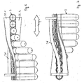
- the preforms are arranged hanging, as in FIG. 11 and passing through different pitches of the transport path, positive and negative pitch areas are traversed, that is, in the positive pitch areas, center axes of adjacent preforms are spaced apart, while adjacent preforms are forced into the negative pitch area in the area following ring collar 28 and avoid each other, so that the preforms are no longer guided in a plane and jam.
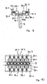
- a deflection element 40 with a rounded sliding surface 41 is inserted in the region of the slot 25, a deflection element 40 with a rounded sliding surface 41 is inserted.
- the preforms 2 are deflected so that they have more space in the negative arc area available and the disadvantage of a negative slope is canceled.
- slip planes 32.1 and 32.2 sections pass through different heights, so that the preforms 2 are tilted outwards in this area.
- FIG. 16 also the possibility of the sliding plane 32.1 and 32.2 inclined to arrange at different heights, so that also the preforms 2 are tilted outwards.
Landscapes
- Engineering & Computer Science (AREA)
- Mechanical Engineering (AREA)
- Manufacturing & Machinery (AREA)
- Blow-Moulding Or Thermoforming Of Plastics Or The Like (AREA)
- Attitude Control For Articles On Conveyors (AREA)
- Structure Of Belt Conveyors (AREA)
- Framework For Endless Conveyors (AREA)
- Control And Other Processes For Unpacking Of Materials (AREA)
- Chain Conveyers (AREA)
- Specific Conveyance Elements (AREA)
- Re-Forming, After-Treatment, Cutting And Transporting Of Glass Products (AREA)
- Branching, Merging, And Special Transfer Between Conveyors (AREA)
- Processing And Handling Of Plastics And Other Materials For Molding In General (AREA)
Description
- Die Erfindung betrifft eine Vorrichtung zum Transportieren von Gegenständen nach dem Oberbegriff von Anspruch 1.
- Eine Vielzahl von Gegenständen müssen heute von einer Bearbeitungsstation zur nächsten oder zur Verpackung transportiert werden. Dies gilt beispielsweise für Flaschen, die auf ihrem Transport noch gefüllt oder etikettiert werden. Vor allem gilt dies aber für Vorformlinge (Preforms), die in einer Spritzgiessmaschine hergestellt und dann in einer Blasformvorrichtung zu einer Flasche aufgeblasen werden. Diese Vorformlinge besitzen einen Ringkragen, der im wesentlichen zur Handhabung der Vorformlinge und späteren Flaschen dient. Der Ringkragen ist nahe unterhalb der Flaschenöffnung vorgesehen und begrenzt in der Regel auch das Gewinde für das Aufschrauben eines Schraubverschlusses.
- Für den Transport von Flaschen sind beispielsweise aus der
DE 35 15 353 A1 Scharnierketten, Flachriemen, Rundprofilschnüren od. dgl. bekannt, welche den Ringkragen untergreifen und so den Transport bewirken. - In der
EP 0 842 875 A1 wird der Ringkragen von je einem Paar von Endlosschnüren über- bzw. untergriffen. - Nach der heutigen Technik werden die im Spritzgiesswerkzeug hergestellten Vorformlingen in komplizierten und viel Platz beanspruchenden Anlagen geordnet und zu der Blasformeinrichtung transportiert. Neu ist es, diese Vorformlinge in einem zentrifugenartigen Separator zu vereinzeln, wie er beispielsweise in der
WO 2006/084831 A1 beschrieben ist. - Des weiteren ist aus der
DE 299 01 401 U1 ein Flaschenförderer bekannt, bei dem die Flaschen auf zwei Führungsschienen geführt werden. Ein Abstand der Schienen voneinander kann durch Verschieben von entsprechenden Halterungen auf einfache Weise schnell an die Halsabmessung der zu fördernden Flaschen angepasst werden. - Aus der
WO 01/85580 A1 WO 97/10163 A1 - Aus der
DE 35 15 353 A1 ist wiederum eine gattungsgemäße Vorrichtung zum Transportieren von Flaschen mit einem Ringkragen mit Hilfe von einer Transporteinrichtung zwischen zwei Gleitebenen, auf denen der Ringkragen aufliegt, bekannt, wobei die Vorrichtung ein einen Gehäuseschlitz aufweisendes Gehäuse aufweist, wobei das Gehäuse aus zwei Gehäuseschalen zusammengesetzt ist und wobei die Randkanten des Gehäuseschlitzes die Gleitebene aufweisen. - Aufgabe der vorliegenden Erfindung ist es, eine geeignete Vorrichtung der oben genannten Art zur Verfügung zu stellen, mit der die Gegenstände, speziell die Vorformlinge, geordnet und sicher von der einen zur nächsten Station transportiert werden können.
- Zur Lösung der Aufgabe führt der Gegenstand des Anspruchs 1.
- Ein Gedanke der vorliegenden Erfindung bezieht sich auf die Ausgestaltung der Gleitbahnen, deren Abstand zueinander veränderbar ist. Zu diesem Zweck sind die Gleitbahnen Teil eines Gehäuses, welches bevorzugt aus zwei Gehäuseschalen besteht. Die beiden Gehäuseschalen bilden im Bereich der Gleitbahnen einen Schlitz aus, wobei Randkanten einen gewünschten Abstand voneinander einhalten. Die Randkanten nehmen in Gebrauchslage zwischen sich die Vorformlinge auf.
- Um nun diesen Abstand ändern zu können, sollen die beiden Gehäuseschalen ineinander verschiebbar sein, wozu sich beispielsweise zwei Schenkelstreifen der Gehäuseschalen überlappen und so überlappend miteinander verbunden werden können.
- Die Behälter, die transportiert werden, weisen vorzugsweise einen Rumpf, einen Ringkragen und eine Mündung auf, und sie sind vorzugsweise PET-Flaschen bzw. PET-Vorformlinge. Zur Unterstützung und zum Transport der Behälter sind die Gleitbahnen und Transporteinrichtungen vorgesehen, wobei die Gleitbahnen vorzugsweise ortsfest angebracht sind. Die Gleitbahnen können z.B. von Kunststoff- oder Metallleisten gebildet werden. Die Gleitbahnen können aber nicht nur als Leiste ausgebildet sein, vielmehr ist eine beliebige Ausgestaltung, wie z.B. in der Art eines mit kreisrundem Querschnitt versehenen Bandes möglich.
- Die mindestens eine Transporteinrichtung ist vorzugsweise für den Hauptenergieeintrag in die Behälter zur Vorwärtsbewegung in Transportrichtung zuständig. Das Gleitbahnen und die Transporteinrichtung greifen vorzugsweise unterhalb bzw. oberhalb des Ringkragens ein. Eine den Ringkragen berührende Ineingriffnahme der Gleitbahnen bzw. Transporteinrichtung ist genauso denkbar, wie eine mit leichtem Abstand zum Ringkragen durchgeführte Ineingriffnahme.
- Die mindestens eine Transporteinrichtung ist als ein endlos umlaufendes Trum ausgebildet, an dem Federelemente angebracht sind. Durch Zusammenwirken der Federelemente mit Federelementen anderer Transporteinrichtungen ergibt sich eine klemmende Erfassung der Behälter im Bereich des Ringkragens.
- Gemäss einer bevorzugten Weiterbildung der Erfindung sind die Gleitbahnen unbeweglich und die Transporteinrichtung in Transportrichtung beweglich angebracht, wobei weiter bevorzugt zwei Gleitbahnen und zwei Transporteinrichtungen vorhanden sind. Vorzugsweise werden die Behälter hängend so transportiert, dass die Gleitbahnen parallel tangential unterhalb dem Ringkragen eingreifen, während die beiden Transporteinrichtungen tangential parallel oberhalb des Ringkragens angebracht sind. Es liegt aber auch im Bereich der Erfindung, dass drei Gleitbahnen vorhanden sind, die den Behälter in einer bestimmten Lage halten, währenddessen eine Transporteinrichtung für die Vorwärtsbewegung in Transportrichtung sorgt.
- Zumindest ein Teil der Transporteinrichtung, welche dem Gegenstand reibschlüssig anliegt, stützt sich gegen Druckrollen ab. Diese Druckrollen sind nachgiebig gelagert . Hierdurch wird ein sicherer Transport der Vorformlinge gewährleistet. In einem Ausführungsbeispiel der Erfindung sind die Druckrollen an Federzungen, Blattfedern, Federbügel od.dgl. gelagert, die vorgespannt sind. In einem weiteren Ausführungsbeispiel der Erfindung können die Druckrollen an einem Lagerblock angeordnet sein, der sich dann wiederum über eine Feder gegen eine Wand abstützt. Damit diese Feder nicht seitlich ausbricht, umschlingt sie bevorzugt einen Bolzen, über den der Lagerblock in die Wand eingesetzt ist.
- In einem Ausführungsbeispiel der Erfindung können dem zu transportierenden Gegenstand beidseitig Endlosriemen, bevorzugt Endlosrundriemen, zugeordnet werden, zwischen denen dann der zu transportierende Gegenstand eingeklemmt ist. Durch die Wahl von im Querschnitt runden Endlosriemen findet keine Änderung der Angriffspunkte an den Gegenständen statt, gleichgültig in welcher Lage die Vorformlinge transportiert werden.
- Diese Endlosriemen umschlingen vorzugsweise beabstandet angeordnete Umlenkrollen, die bevorzugt kippbar sind, sodass durch Veränderung der Lage der Umlenkrollen Vorformlinge nicht nur hängend, sondern auch waagrecht oder sogar senkrecht aufstehend transportiert werden können, je nach Wunsch. Hier hilft zusätzlich noch ein Niederhalter, an dem die Vorformlinge anschlagen bzw. anliegen. Das heisst, die Vorformlinge können in jeder beliebigen Lage und ungetaktet transportiert werden, was bei den bislang bekannten Vorrichtungen nicht möglich war. Zum Beispiel war bislang kein Transport und Staudruckerzeugung von Vorformlingen von unten nach oben möglich. Mit der erfindungsgemässe Vorrichtung ist dies machbar.
- Selbstverständlich müssen auch die Gleitebenen bzw. Unterstützungsmittel der gewünschten Transportbahn angepasst werden. Auf diese Weise ist jede beliebige Führung der Vorformlinge möglich. Dies hat zur Folge, dass die räumliche Ausrichtung der Vorformlinge einem Einlauf an einer Blasmaschine unterschiedlichster Hersteller angepasst werden kann.
- Speziell beim Transport von Vorformlingen aber auch von Flaschen besteht die Notwendigkeit, dass sich die Transportbahn in einer Ebene erstreckt. Verläuft die Transportbahn jedoch ansteigend bzw. abfallend und durchläuft dort unterschiedliche Steigungen, so gibt es positive und negative Steigungsbereiche, in denen sich der Abstand der Mittelachsen von aufeinander folgenden Gegenständen verringert bzw. erweitert. Verringert sich der Abstand, so weichen die aufeinander folgenden Gegenstände aus, benötigen mehr Platz und können sich verkeilen. Ferner reiben sie aneinander.
- Um diesem Nachteil vorzubeugen, wird gemäss der vorliegenden Erfindung in einem Ausführungsbeispiel die Möglichkeit eröffnet, dass ein Auslenkelement in den Bereich der negativen Steigung in die Transportbahn der Gegenstände eingesetzt wird, sodass diese an einer Gleitfläche entlang gleiten und nach aussen gelenkt werden. Hierdurch wird der sich verringernde Abstand zwischen den Mittelachsen von aufeinander folgenden Vorformlingen wieder erhöht.
- Denkbar ist auch, dass die Gleitebenen, auf denen die Ringkrägen der Vorformlinge entlang gleiten, in einzelnen Bereichen in unterschiedlichen Ebenen verlaufen. Hierdurch erfolgt ein Kippen der Vorformlinge, sodass diese ebenfalls seitlich ausgelenkt werden und der Abstand ihrer Mittelachsen wieder erhöht wird.
- Denkbar ist auch das Anordnen von unterschiedlich geneigten Gleitebenen, die zudem noch versetzt in unterschiedlichen Höhen verlaufen können. Hier sind viele Möglichkeiten denkbar und sollen von der vorliegenden Erfindung umfasst sein.
- Gerade die Möglichkeit, welche die vorliegenden Erfindung durch die unterschiedliche Anordnung der Gleitebenen bietet, lässt beispielsweise das Problem eines Negativbogens gar nicht erst entstehen. Die Vorformlinge können in beliebiger Lage ihrer Mittelachsen transportiert werden, sodass dem gewünschten Abstand der Mittelachsen durch Änderung der Lage der Vorformlinge im Raum Rechnung getragen werden kann.
- Weitere Vorteile, Merkmale und Einzelheiten der Erfindung ergeben sich aus der nachfolgenden Beschreibung bevorzugter Ausführungsbeispiele sowie anhand der Zeichnung; diese zeigt in
-
Figur 1 eine perspektivische Ansicht einer Ausführungsform der erfindüngsgemässen Vorrichtung zum Transportieren von Vorformlingen; -
Figur 2 eine vergrössert dargestellte Seitenansicht aus einem Teilbereich der Vorrichtung gemässFigur 1 ; -
Figur 3 einen Querschnitt durchFigur 2 entlang Linie III - III; -
Figur 4 einen Querschnitt durchFigur 2 entlang Linie IV - IV; -
Figur 5 eine schematische Seitenansicht von Teilen der Vorrichtung gemässFigur 3 in verschiedenen Anordnungen von Endlosriemen; -
Figur 6 eine Seitenansicht eines Teilausschnitts aus einer Vorrichtung zur Transportlageänderung von Gegenständen ; -
Figur 7 eine Draufsicht auf den Teilausschnitt gemässFigur 6 ; -
Figur 8 eine schematische Darstellung von verschiedenen Transportlagen von Vorformlingen ; -
Figur 9 eine Schnittansicht von Teilen eines weiteren Ausführungsbeispieis einer erfindungsgemäßen vorrichtung zum Transportieren von Vorformlingen; -
Figur 10 eine Draufsicht auf die Teile der Vorrichtung gemässFigur 9 ; -
Figur 11 eine Seitenansicht eines Teils einer Transportstrecke nach dem Stand der Technik ; -
Figur 12 eine Sicht in Transportrichtung der Vorformlinge mit weiteren Teilen der Vorrichtung zum Transportieren dieser Vorformlinge; -
Figur 13 eine Unteransicht auf den Teilbereich der Vorrichtung gemässFigur 12 ; -
Figur 14 eine Seitenansicht eines weiteren Ausschnitts aus einem weiteren Ausführungsbeispiel einer erfindungsgemässen Vorrichtung zum Transportieren von Gegenständen; -
Figur 15 eine perspektivische Ansicht des Teilbereichs gemäss Figur 18; -
Figur 16 eine weitere perspektivische Ansicht eines weiteren Teilbereichs einer Vorrichtung zum Transportieren von Gegenständen. - Eine erfindungsgemässe Vorrichtung zum Transportieren von Vorformlingen 2 weist gemäss
Figur 2 und 3 ein Gehäuse 22 auf, welches aus zwei Gehäuseschalen 23.1 und 23.2 gebildet ist. Die Gehäuseschalen 23.1 und 23.2 sind ineinander verschiebbar, sodass ein Abstand a von Randkanten 24.1 und 24.2, die einen Schlitz 25 zwischen sich ausbilden, verändert werden kann. Hierzu überlappen sich die beiden Gehäuseschalen 23.1 und 23.2 mit ihren oberen Schenkeln 26.1 und 26.2 und sind in diesem Überlappungsbereich durch nicht näher gezeigte Befestigungselemente, welche inFigur 1 gezeigte Langlöcher 27 durchsetzen, verbunden. - In dem Schlitz 25 gleiten die Vorformlinge 2, wobei sie mit dem Ringkragen 3 Gleitebenen 32.1, 32.2 seitlich anschliessend an die Randkanten 24.1 und 24.2 aufliegen.
- Dem Transport der Vorformlinge 2 entlang dem Schlitz 25 in dem Gehäuse 22 dienen zwei beidseitig angeordnete Endlosriemen 29.1 und 29.2, die Umlenkrollen 30.1 und 30.2 umschlingen und in Kunststoffschienen 42 laufen. Dabei schmiegen sich die Endlosriemen 29.1 und 29.2 oberhalb des Ringkragens 3 eng an den Hals der Vorformlinge 2 an und nehmen die Vorformlinge 2 reibschlüssig mit. Damit die Vorformlinge 2 nicht nach oben ausweichen können, dient zusätzlich eine Schiene 31 als Niederhalter.
- In
Figur 5 sind die beiden Gleitebenen 32.1 und 32.2 angedeutet, auf denen der Ringkragen 3 entlang gleitet. Strichpunktiert sind aber weitere verschiedene Gebrauchslagen der Umlenkrollen 30.1 bzw. 30.2 angedeutet, sodass ersichtlich wird, dass die entsprechenden Endlosriemen 29.1 und 29.2 den Vorformling 2 in jeder gewünschten Position angreifen und weitertransportieren können, je nachdem welche Lage konstruktiv zu bevorzugen ist. Dies hängt vor allem auch davon ab, ob ein hängender Transport des Vorformlingen, ein waagrechter oder gar ein senkrechter Transport gewünscht wird. Die letzten beiden erwähnten Transportmöglichkeiten sind inFigur 8 angedeutet. In denFiguren 6 und 7 wird gezeigt, dass durch eine Führung der Gleitebenen 32.1 und 32.2 ohne Schwierigkeiten ein Ausrichten der Vorformlinge von einer waagerechten Lage in einer hängenden Lage möglich ist. Dasselbe gilt natürlich auch für ein Ausrichten der Vorformlinge von einer hängenden In eine waagerechte Lage und von dort sogar in eine senkrechte Lage. - Gemäss den
Figuren 3 und4 greifen die beiden Endlosriemen 29.1 und 29.2 die Vorformlinge 2 von je einer Seite her an, sodass die Vorformlinge 2 bei ihrem Transport durch den Schlitz 25 bewegt werden. Damit die Endlosriemen 29.1 und 29.2 in engem, das heisst in reibschlüssigem Kontakt mit den Vorformlingen 2 gelangen, sind seitliche Druckrollen 33.1 und 33.2 vorgesehen, die die Endlosriemen 29.1 und 29.2 federnd gegen den Hals des Vorformlings 2 oberhalb des Ringkragens 3 drücken. Diese Druckrollen 33.1 und 33.2 laufen. mit den Endlosriemen 29.1 und 29.2. Dabei drehen sie um eine Drehachse 34.1 und 34.2, wobei sie jeweils an einer Federzunge 35.1 und 35.2 hängen, welche vorgespannt ist und die Druckrollen 33.1 und 33.2 gegen den Endlosriemen 29.1 und 29.2 drückt. - Bei einer weiteren Ausführungsform einer erfindungsgemässen Vorrichtung zum Transport von Vorformlingen 2 gemäss den
Figuren 9 und 10 sind die Druckrollen 33.1 und 33.2 jeweils an einem Lagerblock 36.1 und 36.2 angeordnet, wobei jeder Lagerblock 36.1 und 36.2 über einen Bolzen 37.1 und 37.2 an einer Wand 38.1 und 38.2 gehalten ist. Gegen diese Wand 38.1 und 38.2 stützt sich jeder Lagerblock 36.1 bzw. 36.2 über eine Schraubenfeder 39 ab, welche den Bolzen 37.1 und 37.2 umschlingt. Diese Schraubenfeder 39 ist ebenfalls vorgespannt, sodass die Druckrollen 33.1 und 33.2 den Endlosriemen 29.1 und 29.2 gegen den Vorformling 2 drücken. - Es ist auch möglich, Vorformlinge entlang eine kurvige Transportbahn zu transprotieren. Werden beispielsweise die Vorformlinge hängend angeordnet, wie dies in
Figur 11 gezeigt ist, und durchlaufen sie unterschiedliche Steigungen der Transportbahn, so werden positive und negative Steigungsbereiche durchlaufen, das heisst, in den positiven Steigungsbereichen beabstanden sich Mittelachsen benachbarter Vorformlinge mehr, während benachbarte Vorformlinge in den negativen Steigungsbereich in dem auf dem Ringkragen 28 folgenden Bereich gegeneinander gedrückt werden und sich gegenseitig ausweichen, so dass die Vorformlinge nicht mehr in einer Ebene geführt sind und verklemmen. - Gemäss
Figur 12 und 13 wird in dem Bereich des Schlitzes 25 ein Auslenkelement 40 mit einer gerundeten Gleitfläche 41 eingesetzt. Im Bereich dieser Gleitfläche 41 werden die Vorformlinge 2 ausgelenkt, sodass ihnen mehr Platz im Negativbogenbereich zur Verfügung steht und der Nachteil einer negativen Steigung aufgehoben wird. - Eine andere Möglichkeit gemäss den
Figuren 14 und 15 besteht darin, dass die Gleitebenen 32.1 und 32.2 abschnittsweise unterschiedliche Höhen durchlaufen, sodass die Vorformlinge 2 in diesem Bereich nach aussen gekippt werden. - Ferner besteht gemäss
Figur 16 auch die Möglichkeit, die Gleitebene 32.1 und 32.2 geneigt in unterschiedlichen Höhen anzuordnen, sodass ebenfalls die Vorformlingen 2 nach aussen gekippt werden. -
1 34 Drehachse 67 2/2.1 Vorformling/Flaschen 35 Federzunge 68 3 Ringkragen 36 Lagerblock 69 4 37 Bolzen 70 5 38 Wand 71 6 39 Schraubenfeder 72 7 40 Auslenkelement 73 8 41 Gleltfläche 74 9 42 75 10 43 76 11 44 77 12 45 78 13 46 79 14 47 15 48 16 49 a Abstand 17 50 18 51 19 52 T Transportrichtung 20 53 21 54 22 Gehäuse 55 23 Gehäuseschale 56 24 Randkante 57 25 Schlitz 58 26 Schenkel 59 27 Langloch 60 28 61 29 Endlosriemen 62 30 Umlenkrollen 63 31 Niederhalter 64 32 Gleitebene 65 33 Druckrolle 66
Claims (10)
- Vorrichtung zum Transportieren von Gegenständen (2) mit einer Profilierung (3), insbesondere von Flaschen oder Vorformlingen mit einem Ringkragen, zwischen zwei Gleitebenen (32.1, 32.2), auf denen die Profilierung (3) der Gegenstände (2) aufliegt, mit:- einem Gehäuse (22), das die beiden Gleitebenen (32.1, 32.2) und zwei Randkanten (24.1, 24.2), die einen Gehäuseschlitz (25) zwischen sich ausbilden, aufweist, wobei die Gleitebenen (32.1, 32.2) sich an die Randkanten (24.1, 24.2) seitlich anschliessen,- einer innerhalb des Gehäuses (22) angeordneten Transporteinrichtung zum Transportieren der Gegenstände (2) zwischen den beiden Gleitebenen (32.1, 32.2),dadurch gekennzeichnet,
dass das Gehäuse (22) aus zwei Gehäuseschalen (23.1, 23.2) zusammengesetzt ist, wobei die beiden Gehäuseschalen (23.1, 23.2) verschiebbar ineinander geführt sind, so dass der Abstand (a) der Gleitebenen (32.1, 32.2) zueinander veränderbar ist, dass die Transporteinrichtung ein Endlosriemen (29.1, 29.2) ist, und
dass Druckrollen (33.1, 33.2) federnd in einer Gehäuseschale (23.1, 23.2) angeordnet sind, wobei die Druckrollen (33.1, 33.2) den Endlosriemen (29.1, 29.2) federnd gegen die zu transportierenden Gegenstände (2) drücken, so dass der Endlosriemen (29.1, 29.2) in reibschlüssigem Kontakt mit den zu transportierenden Gegenständen (2) gelangt. - Vorrichtung nach Anspruch 1, dadurch gekennzeichnet, dass die Druckrollen (33.1, 33.2) an Federzungen (35.1, 35.2) gelagert sind.
- Vorrichtung nach Anspruch 1 dadurch gekennzeichnet, dass die Druckrollen (33.1 , 33.2) an einem Lagerblock (36.1 , 36.2) angeordnet sind, der sich über eine Feder (39.1 , 39.2) gegen eine Wand (38.1 , 38.2) abstützt.
- Vorrichtung nach Anspruch 3, dadurch gekennzeichnet, dass die Feder (39.1, 39.2) einen Bolzen (37.1, 37.2) umschlingt, der in die Wand (38.1, 38.2) eingesetzt ist.
- Vorrichtung nach wenigstens einem der Ansprüche 1 bis 4, dadurch gekennzeichnet, dass der Endlosriemen (29.1, 29.2) zumindest zwei Umlenkrollen (30.1, 30.2) umschlingt.
- Vorrichtung nach Anspruch 5, dadurch gekennzeichnet, dass die Umlenkrollen (30.1, 30.2) parallel zur Vertikalachse des Gegenstandes (2) angeordnet sind.
- Vorrichtung nach Anspruch 5 oder 6, dadurch gekennzeichnet, dass die Umlenkrollen (30.1, 30.2) kippbar sind.
- Vorrichtung nach wenigstens einem der Ansprüche 1 bis 7, gekennzeichnet durch einen Niederhalter (31), so angeordnet, dass die Gegenstände nicht nach oben ausweichen können.
- Vorrichtung nach wenigstens einem der Ansprüche 1 bis 8, dadurch gekennzeichnet, dass ihr eine Einrichtung (40) zum Auslenken der der Gegenstände (2) aus Ihrer Transportbahn zugeordnet ist.
- Vorrichtung nach Anspruch 9, dadurch gekennzeichnet, dass die Einrichtung (40) zum Auslenken der Gegenstände (2) aus zumindest einer zusätzlichen Gleitfläche (41) besteht, die in den Bereich der Transportbahn eingreift.
Applications Claiming Priority (3)
| Application Number | Priority Date | Filing Date | Title |
|---|---|---|---|
| DE200510043282 DE102005043282A1 (de) | 2005-09-09 | 2005-09-09 | Behältertransportvorrichtung |
| DE200610038320 DE102006038320A1 (de) | 2006-08-15 | 2006-08-15 | Vorrichtung zum Transportieren von Gegenständen |
| EP06805672A EP1922269B1 (de) | 2005-09-09 | 2006-09-08 | Vorrichtung zum transportieren von gegenständen |
Related Parent Applications (1)
| Application Number | Title | Priority Date | Filing Date |
|---|---|---|---|
| EP06805672.0 Division | 2006-09-08 |
Publications (2)
| Publication Number | Publication Date |
|---|---|
| EP2213594A1 EP2213594A1 (de) | 2010-08-04 |
| EP2213594B1 true EP2213594B1 (de) | 2013-05-29 |
Family
ID=37807997
Family Applications (2)
| Application Number | Title | Priority Date | Filing Date |
|---|---|---|---|
| EP06805672A Not-in-force EP1922269B1 (de) | 2005-09-09 | 2006-09-08 | Vorrichtung zum transportieren von gegenständen |
| EP10001941.3A Not-in-force EP2213594B1 (de) | 2005-09-09 | 2006-09-08 | Vorrichtung zum Transportieren von Gegenständen mit einer Profilierung, insbesondere von Flaschen oder Vorformelingen |
Family Applications Before (1)
| Application Number | Title | Priority Date | Filing Date |
|---|---|---|---|
| EP06805672A Not-in-force EP1922269B1 (de) | 2005-09-09 | 2006-09-08 | Vorrichtung zum transportieren von gegenständen |
Country Status (7)
| Country | Link |
|---|---|
| US (1) | US7861852B2 (de) |
| EP (2) | EP1922269B1 (de) |
| JP (2) | JP2009507736A (de) |
| CN (1) | CN102303769B (de) |
| AT (1) | ATE489312T1 (de) |
| DE (1) | DE502006008394D1 (de) |
| WO (1) | WO2007028627A2 (de) |
Families Citing this family (31)
| Publication number | Priority date | Publication date | Assignee | Title |
|---|---|---|---|---|
| ITPR20060017A1 (it) * | 2006-03-01 | 2007-09-02 | Secondo Lecchini | Dispositivo di trascinamento meccanico di contenitori in plastica vuoti e provvisti di collare, in condizione sospesa. |
| JP5557527B2 (ja) | 2006-08-15 | 2014-07-23 | シドル パルティシパティオン エス.アー.エス. | 容器から桿状体を配送する装置及び方法並びに後続の搬送装置 |
| DE102006055963B4 (de) * | 2006-11-24 | 2016-10-27 | Sidel Participations S.A.S. | Vorrichtung zur Überführung von hohlen zylindrischen Gegenständen |
| USD769720S1 (en) | 2007-12-21 | 2016-10-25 | Silgan Plastics Llc | Preform for dosing bottle |
| US8057733B2 (en) * | 2007-12-21 | 2011-11-15 | Silgan Plastics Corporation | Dosing bottle and method |
| FR2930241B1 (fr) * | 2008-04-18 | 2010-09-10 | Sidel Participations | Dispositif de convoyage vrille pour preformes |
| CN101823329B (zh) * | 2009-04-27 | 2012-08-29 | 江苏新美星包装机械有限公司 | 吹瓶机的输瓶装置 |
| IT1395401B1 (it) * | 2009-09-04 | 2012-09-14 | Lecchini | Dispositivo di trascinamento e rilascio meccanico di contenitori |
| FR2956652B1 (fr) * | 2010-02-25 | 2015-12-11 | Sidel Participations | Installation de convoyage d'articles en materiau thermoplastique |
| JP4662193B1 (ja) * | 2010-06-04 | 2011-03-30 | 株式会社エーエフシー | 採血管ストッカー及び採血管準備装置 |
| GB2482473A (en) * | 2010-06-29 | 2012-02-08 | Constar Internat Uk Ltd | Inspection of articles |
| CH704401A1 (de) | 2011-01-28 | 2012-07-31 | M Tanner Ag | Fördereinrichtung für zylindrische Körper, mit in Förderrichtung geneigten Ablaufschienen. |
| AT13041U1 (de) * | 2011-11-08 | 2013-05-15 | Gassner Gmbh | Beschickungsvorrichtung für behälterverschlüsse |
| DE102012011763A1 (de) * | 2012-06-15 | 2013-12-19 | Khs Corpoplast Gmbh | Vorrichtung zum Transport von Vorformlingen |
| DE102012024420A1 (de) * | 2012-12-14 | 2014-07-03 | Krones Ag | Optimierte Vorformlingzuführung |
| JP5993355B2 (ja) * | 2013-07-05 | 2016-09-14 | 株式会社 日立産業制御ソリューションズ | 異物検査装置および異物検査装置のシリンジ回収方法 |
| CH708587A1 (de) * | 2013-09-16 | 2015-03-31 | M Tanner Ag | Klemmförderer mit zumindest einer Spanneinheit. |
| FR3028254B1 (fr) * | 2014-11-10 | 2019-04-12 | Sidel Participations | Procede de transport de preformes de recipients en matiere plastique |
| CA3027347C (en) | 2016-06-22 | 2023-08-08 | Corning Incorporated | Apparatuses for holding and conveying glass articles |
| US11014849B2 (en) | 2016-11-30 | 2021-05-25 | Corning Incorporated | Systems and methods for ion exchanging glass articles |
| EP3453648B1 (de) | 2017-09-07 | 2024-04-03 | M. Tanner AG | Zulaufvorrichtung |
| KR101865094B1 (ko) * | 2017-09-14 | 2018-06-07 | 신우코스텍(주) | 입체 형상을 갖는 용기의 제조 장치 |
| CN107672992A (zh) * | 2017-11-08 | 2018-02-09 | 张家港市华申工业橡塑制品有限公司 | 用于输送多规格球状物的卡爪输送带 |
| CN109850251A (zh) * | 2018-08-07 | 2019-06-07 | 安徽御流包装机械有限公司 | 纸尿裤包装机的翻转过渡设备及纸尿裤包装机 |
| FR3092099B1 (fr) | 2019-01-24 | 2021-01-29 | Tiama | Procédé et dispositif de convoyage de récipients en position suspendue |
| CN109745231A (zh) * | 2019-02-27 | 2019-05-14 | 四川制药制剂有限公司 | 一种制备帕瑞昔布冻干粉针剂的系统 |
| CN114180264B (zh) * | 2021-12-15 | 2023-12-05 | 北新建材(苏州)有限公司 | 一种过渡式石膏板输送装置 |
| FR3142465A1 (fr) * | 2022-11-29 | 2024-05-31 | Sidel Participations | Procede de determination de la force de poussee produite par un convoyeur d’accumulation |
| DE102023118975B4 (de) * | 2023-07-18 | 2025-11-06 | Körber Pharma Inspection Gmbh | Einsatz für eine Wendevorrichtung, Wendevorrichtung und Verfahren zum Wenden von medizinischen Ampullen |
| CN117361092B (zh) * | 2023-10-26 | 2024-05-24 | 东莞市欧宇精密科技有限公司 | 一种应用于t型装配件的阵列取放机构 |
| CN119750119B (zh) * | 2025-03-07 | 2025-05-13 | 泰兴市吉力玻璃制品有限公司 | 一种玻璃瓶生产用辅助输送机 |
Family Cites Families (34)
| Publication number | Priority date | Publication date | Assignee | Title |
|---|---|---|---|---|
| US3951257A (en) * | 1974-10-30 | 1976-04-20 | Pitney-Bowes, Inc. | Mail transporting mechanism |
| US4479574A (en) * | 1982-04-21 | 1984-10-30 | S. J. Industries, Inc. | Container transport apparatus |
| JPS6139338U (ja) * | 1984-08-10 | 1986-03-12 | 三菱重工業株式会社 | 未加工ワ−ク検出装置 |
| DE3515353A1 (de) | 1985-04-27 | 1986-10-30 | Seitz Enzinger Noll Maschinenbau Ag, 6800 Mannheim | Vorrichtung zum foerdern von flaschen in haengender lage |
| NL8901014A (nl) * | 1989-04-21 | 1990-11-16 | Soltec Bv | Geleidingsinrichting voor voorwerpen zoals "printed circuit boards". |
| IT1239102B (it) * | 1990-02-15 | 1993-09-21 | Nuova O M I P | Linea di trasferimento di contenitori in plastica vuoti. |
| JPH0794067B2 (ja) * | 1990-10-08 | 1995-10-11 | 権士 近藤 | プリント基板の保持搬送方法およびその装置 |
| JP2586380Y2 (ja) * | 1992-08-10 | 1998-12-02 | 花王株式会社 | 物品供給装置 |
| JP2720774B2 (ja) * | 1993-11-16 | 1998-03-04 | 東洋製罐株式会社 | 成形容器搬送用のエアフローコンベヤ装置 |
| WO1996006691A1 (de) * | 1994-08-30 | 1996-03-07 | Hulskotte Jan Hendrik | Vorrichtung und verfahren zur reinigung von bestecken |
| JPH0957824A (ja) * | 1995-08-25 | 1997-03-04 | Mitsubishi Heavy Ind Ltd | パリソン搬送装置 |
| IT1280736B1 (it) * | 1995-09-15 | 1998-02-06 | Sasib Beverage Medium Speed Sp | Procedimento di trasporto per contenitori, in particolare per conteni- tori in materiale plastico in condizione sospesa, e trasportatore |
| JP3477303B2 (ja) * | 1996-02-08 | 2003-12-10 | 三菱重工業株式会社 | プリフォーム取出し、整列装置 |
| IL118123A0 (en) * | 1996-05-02 | 1996-09-12 | Farkas Shmuel | Conveyor propulsion system |
| JPH1035847A (ja) * | 1996-07-25 | 1998-02-10 | Yoshino Kogyosho Co Ltd | 搬送チェーン装置 |
| US5875880A (en) * | 1996-11-08 | 1999-03-02 | Standard-Knapp, Inc. | Article grouper and escapement for continuous motion packer |
| US6109426A (en) * | 1996-11-13 | 2000-08-29 | Simplimatic Engineering Company | Oriented bottle conveyor |
| JPH111212A (ja) * | 1997-06-11 | 1999-01-06 | Kirin Beverage Kk | 電子線による容器の滅菌装置 |
| NL1008133C2 (nl) * | 1998-01-27 | 1999-07-28 | Stork Nolte Emt B V | Flessentransporteur. |
| DE19821105A1 (de) * | 1998-05-12 | 1999-11-18 | Krones Ag | Vorrichtung und Verfahren zur Herstellung von Kunststoffhohlkörpern |
| IT1305266B1 (it) * | 1998-06-01 | 2001-04-19 | Sipa Spa | Impianto perfezionato per il trasferimento ordinato continuo dipreforme in resina termoplastica. |
| JP2000168945A (ja) * | 1998-12-07 | 2000-06-20 | Kirin Techno System:Kk | プリフォーム検査用搬送装置 |
| JP2000281006A (ja) * | 1999-03-25 | 2000-10-10 | Fuji Seal Inc | 注出口部材の供給装置及び注出口部材の反転装置 |
| FR2796052B1 (fr) * | 1999-07-09 | 2001-09-28 | Netra Systems | Dispositif anti-contamination pour le transport de recipients et convoyeur pneumatique equipe d'un tel dispositif |
| JP2001063807A (ja) * | 1999-08-31 | 2001-03-13 | Sakamoto Engineering:Kk | 搬送装置 |
| US6279729B1 (en) * | 1999-10-15 | 2001-08-28 | Goldco Industries, Inc. | Article conveyance having mechanical drive |
| ITPR20000032A1 (it) * | 2000-05-10 | 2001-11-10 | Marco Priero | Apparato e procedimento di trasporto per contenitori, in particolare per contenitori in materiale plastico provvisti di collare sporgente |
| JP3887521B2 (ja) * | 2000-06-30 | 2007-02-28 | マルヤス機械株式会社 | ベルトコンベア |
| DE20110929U1 (de) * | 2001-07-06 | 2002-11-14 | Wippermann jr. GmbH, 58091 Hagen | Fördereinrichtung mit Förderkette |
| JP4553532B2 (ja) * | 2001-09-11 | 2010-09-29 | 共同印刷株式会社 | シート送出装置 |
| JP3909579B2 (ja) * | 2002-03-19 | 2007-04-25 | 東洋自動機株式会社 | スパウト又はスパウト付き袋のチェーン式搬送装置 |
| JP2003295672A (ja) * | 2002-03-29 | 2003-10-15 | Canon Inc | 定着装置およびこの定着装置を備えた画像形成装置 |
| JP4403748B2 (ja) * | 2003-08-01 | 2010-01-27 | 岩崎電気株式会社 | 光パルス殺菌装置 |
| DE102004009698A1 (de) * | 2004-02-27 | 2005-09-15 | Krones Ag | Inspektionsmaschine mit einer Vorrichtung zum Transportieren von Hohlkörpern |
-
2006
- 2006-09-08 DE DE502006008394T patent/DE502006008394D1/de active Active
- 2006-09-08 EP EP06805672A patent/EP1922269B1/de not_active Not-in-force
- 2006-09-08 AT AT06805672T patent/ATE489312T1/de active
- 2006-09-08 US US11/991,581 patent/US7861852B2/en not_active Expired - Fee Related
- 2006-09-08 EP EP10001941.3A patent/EP2213594B1/de not_active Not-in-force
- 2006-09-08 WO PCT/EP2006/008772 patent/WO2007028627A2/de not_active Ceased
- 2006-09-08 CN CN201110130374.1A patent/CN102303769B/zh not_active Expired - Fee Related
- 2006-09-08 JP JP2008529553A patent/JP2009507736A/ja active Pending
-
2013
- 2013-05-07 JP JP2013097598A patent/JP2013237567A/ja active Pending
Also Published As
| Publication number | Publication date |
|---|---|
| ATE489312T1 (de) | 2010-12-15 |
| CN102303769B (zh) | 2016-03-30 |
| DE502006008394D1 (de) | 2011-01-05 |
| CN102303769A (zh) | 2012-01-04 |
| WO2007028627A3 (de) | 2007-08-02 |
| WO2007028627A2 (de) | 2007-03-15 |
| EP2213594A1 (de) | 2010-08-04 |
| EP1922269A2 (de) | 2008-05-21 |
| US20090211880A1 (en) | 2009-08-27 |
| US7861852B2 (en) | 2011-01-04 |
| EP1922269B1 (de) | 2010-11-24 |
| JP2013237567A (ja) | 2013-11-28 |
| JP2009507736A (ja) | 2009-02-26 |
Similar Documents
| Publication | Publication Date | Title |
|---|---|---|
| EP1922269B1 (de) | Vorrichtung zum transportieren von gegenständen | |
| EP2346757B1 (de) | Vorrichtung zum vereinzeln und lageausrichten von metallischen behälterverschlüssen | |
| EP0286080B1 (de) | Vorrichtung zum Steuern des Transportweges von Gegenständen | |
| EP2412650B1 (de) | Speichervorrichtung für Behälter und Verfahren zum Speichern von Behältern | |
| DE69506670T2 (de) | Förderanlage zum Erzeugen von Zwischenräumen | |
| EP1628894B1 (de) | Foerderstrecke mit verstellbarem gelaender sowie stellantrieb | |
| DE7311210U (de) | Vorrichtung fuer den vertikalen transport von koerpern | |
| EP3315420A1 (de) | Tiefziehverpackungsmaschine | |
| DE102009026395A1 (de) | Vorrichtung zum Gruppieren und/oder Vereinzeln von Artikeln | |
| DE102005043282A1 (de) | Behältertransportvorrichtung | |
| DE102009033323B4 (de) | Sortiergerät | |
| DE102009009439B4 (de) | Verstellbare Transportrinne für Behältnisverschlüsse | |
| DE2310291C3 (de) | Rutsche für Zigaretten | |
| DE19943164A1 (de) | Übergabeeinrichtung für Kleinteile und Transportrinne | |
| EP2292536A2 (de) | Transportvorrichtung zum Transportieren von Gefäßverschlüssen | |
| DE102016225485A1 (de) | Sicheres Fördersystem | |
| DE4439866C2 (de) | Leitvorrichtung in Verpackungsmaschinen zum Führen und Ordnen von auf Transportbändern herangeführten Gefäßen | |
| DE102004023181B4 (de) | Zuführungsmaschine | |
| DE102006038320A1 (de) | Vorrichtung zum Transportieren von Gegenständen | |
| EP3154879B1 (de) | Transportsystem | |
| DE102018204038A1 (de) | Transportsystem mit verstellbaren transportspuren | |
| WO2019166165A1 (de) | Vorrichtung zum führen von behältern in einer kurve | |
| DE10115906A1 (de) | Transporteinrichtung zum Transportieren und Ausrichten eines Gegenstandes | |
| DE19702716C2 (de) | Vorrichtung zum Transport von Gegenständen | |
| DE102018108395A1 (de) | Arbeitsmodul für eine Verpackungsvorrichtung und Verfahren zum Umgang mit Artikeln und/oder Verpackungsmaterial |
Legal Events
| Date | Code | Title | Description |
|---|---|---|---|
| PUAI | Public reference made under article 153(3) epc to a published international application that has entered the european phase |
Free format text: ORIGINAL CODE: 0009012 |
|
| 17P | Request for examination filed |
Effective date: 20100324 |
|
| AC | Divisional application: reference to earlier application |
Ref document number: 1922269 Country of ref document: EP Kind code of ref document: P |
|
| AK | Designated contracting states |
Kind code of ref document: A1 Designated state(s): AT BE BG CH CY CZ DE DK EE ES FI FR GB GR HU IE IS IT LI LT LU LV MC NL PL PT RO SE SI SK TR |
|
| 17Q | First examination report despatched |
Effective date: 20110530 |
|
| GRAP | Despatch of communication of intention to grant a patent |
Free format text: ORIGINAL CODE: EPIDOSNIGR1 |
|
| GRAS | Grant fee paid |
Free format text: ORIGINAL CODE: EPIDOSNIGR3 |
|
| GRAA | (expected) grant |
Free format text: ORIGINAL CODE: 0009210 |
|
| AC | Divisional application: reference to earlier application |
Ref document number: 1922269 Country of ref document: EP Kind code of ref document: P |
|
| AK | Designated contracting states |
Kind code of ref document: B1 Designated state(s): AT BE BG CH CY CZ DE DK EE ES FI FR GB GR HU IE IS IT LI LT LU LV MC NL PL PT RO SE SI SK TR |
|
| REG | Reference to a national code |
Ref country code: GB Ref legal event code: FG4D Free format text: NOT ENGLISH |
|
| REG | Reference to a national code |
Ref country code: CH Ref legal event code: EP |
|
| REG | Reference to a national code |
Ref country code: AT Ref legal event code: REF Ref document number: 614258 Country of ref document: AT Kind code of ref document: T Effective date: 20130615 |
|
| REG | Reference to a national code |
Ref country code: IE Ref legal event code: FG4D Free format text: LANGUAGE OF EP DOCUMENT: GERMAN |
|
| REG | Reference to a national code |
Ref country code: DE Ref legal event code: R096 Ref document number: 502006012913 Country of ref document: DE Effective date: 20130725 |
|
| REG | Reference to a national code |
Ref country code: LT Ref legal event code: MG4D |
|
| PG25 | Lapsed in a contracting state [announced via postgrant information from national office to epo] |
Ref country code: SE Free format text: LAPSE BECAUSE OF FAILURE TO SUBMIT A TRANSLATION OF THE DESCRIPTION OR TO PAY THE FEE WITHIN THE PRESCRIBED TIME-LIMIT Effective date: 20130529 Ref country code: SI Free format text: LAPSE BECAUSE OF FAILURE TO SUBMIT A TRANSLATION OF THE DESCRIPTION OR TO PAY THE FEE WITHIN THE PRESCRIBED TIME-LIMIT Effective date: 20130529 Ref country code: PT Free format text: LAPSE BECAUSE OF FAILURE TO SUBMIT A TRANSLATION OF THE DESCRIPTION OR TO PAY THE FEE WITHIN THE PRESCRIBED TIME-LIMIT Effective date: 20130930 Ref country code: IS Free format text: LAPSE BECAUSE OF FAILURE TO SUBMIT A TRANSLATION OF THE DESCRIPTION OR TO PAY THE FEE WITHIN THE PRESCRIBED TIME-LIMIT Effective date: 20130929 Ref country code: GR Free format text: LAPSE BECAUSE OF FAILURE TO SUBMIT A TRANSLATION OF THE DESCRIPTION OR TO PAY THE FEE WITHIN THE PRESCRIBED TIME-LIMIT Effective date: 20130830 Ref country code: ES Free format text: LAPSE BECAUSE OF FAILURE TO SUBMIT A TRANSLATION OF THE DESCRIPTION OR TO PAY THE FEE WITHIN THE PRESCRIBED TIME-LIMIT Effective date: 20130909 Ref country code: LT Free format text: LAPSE BECAUSE OF FAILURE TO SUBMIT A TRANSLATION OF THE DESCRIPTION OR TO PAY THE FEE WITHIN THE PRESCRIBED TIME-LIMIT Effective date: 20130529 Ref country code: FI Free format text: LAPSE BECAUSE OF FAILURE TO SUBMIT A TRANSLATION OF THE DESCRIPTION OR TO PAY THE FEE WITHIN THE PRESCRIBED TIME-LIMIT Effective date: 20130529 |
|
| REG | Reference to a national code |
Ref country code: NL Ref legal event code: VDEP Effective date: 20130529 |
|
| PG25 | Lapsed in a contracting state [announced via postgrant information from national office to epo] |
Ref country code: BG Free format text: LAPSE BECAUSE OF FAILURE TO SUBMIT A TRANSLATION OF THE DESCRIPTION OR TO PAY THE FEE WITHIN THE PRESCRIBED TIME-LIMIT Effective date: 20130829 Ref country code: PL Free format text: LAPSE BECAUSE OF FAILURE TO SUBMIT A TRANSLATION OF THE DESCRIPTION OR TO PAY THE FEE WITHIN THE PRESCRIBED TIME-LIMIT Effective date: 20130529 |
|
| PG25 | Lapsed in a contracting state [announced via postgrant information from national office to epo] |
Ref country code: LV Free format text: LAPSE BECAUSE OF FAILURE TO SUBMIT A TRANSLATION OF THE DESCRIPTION OR TO PAY THE FEE WITHIN THE PRESCRIBED TIME-LIMIT Effective date: 20130529 |
|
| PG25 | Lapsed in a contracting state [announced via postgrant information from national office to epo] |
Ref country code: CZ Free format text: LAPSE BECAUSE OF FAILURE TO SUBMIT A TRANSLATION OF THE DESCRIPTION OR TO PAY THE FEE WITHIN THE PRESCRIBED TIME-LIMIT Effective date: 20130529 Ref country code: DK Free format text: LAPSE BECAUSE OF FAILURE TO SUBMIT A TRANSLATION OF THE DESCRIPTION OR TO PAY THE FEE WITHIN THE PRESCRIBED TIME-LIMIT Effective date: 20130529 Ref country code: SK Free format text: LAPSE BECAUSE OF FAILURE TO SUBMIT A TRANSLATION OF THE DESCRIPTION OR TO PAY THE FEE WITHIN THE PRESCRIBED TIME-LIMIT Effective date: 20130529 Ref country code: EE Free format text: LAPSE BECAUSE OF FAILURE TO SUBMIT A TRANSLATION OF THE DESCRIPTION OR TO PAY THE FEE WITHIN THE PRESCRIBED TIME-LIMIT Effective date: 20130529 |
|
| PG25 | Lapsed in a contracting state [announced via postgrant information from national office to epo] |
Ref country code: RO Free format text: LAPSE BECAUSE OF FAILURE TO SUBMIT A TRANSLATION OF THE DESCRIPTION OR TO PAY THE FEE WITHIN THE PRESCRIBED TIME-LIMIT Effective date: 20130529 Ref country code: NL Free format text: LAPSE BECAUSE OF FAILURE TO SUBMIT A TRANSLATION OF THE DESCRIPTION OR TO PAY THE FEE WITHIN THE PRESCRIBED TIME-LIMIT Effective date: 20130529 |
|
| BERE | Be: lapsed |
Owner name: SIDEL PARTICIPATIONS, S.A.S. Effective date: 20130930 |
|
| PLBE | No opposition filed within time limit |
Free format text: ORIGINAL CODE: 0009261 |
|
| STAA | Information on the status of an ep patent application or granted ep patent |
Free format text: STATUS: NO OPPOSITION FILED WITHIN TIME LIMIT |
|
| PG25 | Lapsed in a contracting state [announced via postgrant information from national office to epo] |
Ref country code: MC Free format text: LAPSE BECAUSE OF FAILURE TO SUBMIT A TRANSLATION OF THE DESCRIPTION OR TO PAY THE FEE WITHIN THE PRESCRIBED TIME-LIMIT Effective date: 20130529 |
|
| REG | Reference to a national code |
Ref country code: CH Ref legal event code: PL |
|
| 26N | No opposition filed |
Effective date: 20140303 |
|
| REG | Reference to a national code |
Ref country code: DE Ref legal event code: R097 Ref document number: 502006012913 Country of ref document: DE Effective date: 20140303 |
|
| REG | Reference to a national code |
Ref country code: IE Ref legal event code: MM4A |
|
| PG25 | Lapsed in a contracting state [announced via postgrant information from national office to epo] |
Ref country code: IE Free format text: LAPSE BECAUSE OF NON-PAYMENT OF DUE FEES Effective date: 20130908 Ref country code: BE Free format text: LAPSE BECAUSE OF NON-PAYMENT OF DUE FEES Effective date: 20130930 Ref country code: LI Free format text: LAPSE BECAUSE OF NON-PAYMENT OF DUE FEES Effective date: 20130930 Ref country code: CH Free format text: LAPSE BECAUSE OF NON-PAYMENT OF DUE FEES Effective date: 20130930 |
|
| REG | Reference to a national code |
Ref country code: AT Ref legal event code: MM01 Ref document number: 614258 Country of ref document: AT Kind code of ref document: T Effective date: 20130908 |
|
| PG25 | Lapsed in a contracting state [announced via postgrant information from national office to epo] |
Ref country code: AT Free format text: LAPSE BECAUSE OF NON-PAYMENT OF DUE FEES Effective date: 20130908 |
|
| PG25 | Lapsed in a contracting state [announced via postgrant information from national office to epo] |
Ref country code: TR Free format text: LAPSE BECAUSE OF FAILURE TO SUBMIT A TRANSLATION OF THE DESCRIPTION OR TO PAY THE FEE WITHIN THE PRESCRIBED TIME-LIMIT Effective date: 20130529 Ref country code: CY Free format text: LAPSE BECAUSE OF FAILURE TO SUBMIT A TRANSLATION OF THE DESCRIPTION OR TO PAY THE FEE WITHIN THE PRESCRIBED TIME-LIMIT Effective date: 20130529 |
|
| REG | Reference to a national code |
Ref country code: DE Ref legal event code: R082 Ref document number: 502006012913 Country of ref document: DE Representative=s name: PATENTANWAELTE UND RECHTSANWALT DR. WEISS, ARA, DE Ref country code: DE Ref legal event code: R082 Ref document number: 502006012913 Country of ref document: DE Representative=s name: PATENTANWAELTE UND RECHTSANWALT WEISS, ARAT & , DE |
|
| PG25 | Lapsed in a contracting state [announced via postgrant information from national office to epo] |
Ref country code: LU Free format text: LAPSE BECAUSE OF NON-PAYMENT OF DUE FEES Effective date: 20130908 Ref country code: HU Free format text: LAPSE BECAUSE OF FAILURE TO SUBMIT A TRANSLATION OF THE DESCRIPTION OR TO PAY THE FEE WITHIN THE PRESCRIBED TIME-LIMIT; INVALID AB INITIO Effective date: 20060908 |
|
| REG | Reference to a national code |
Ref country code: FR Ref legal event code: PLFP Year of fee payment: 10 |
|
| PGFP | Annual fee paid to national office [announced via postgrant information from national office to epo] |
Ref country code: GB Payment date: 20150917 Year of fee payment: 10 |
|
| PGFP | Annual fee paid to national office [announced via postgrant information from national office to epo] |
Ref country code: FR Payment date: 20150922 Year of fee payment: 10 |
|
| PGFP | Annual fee paid to national office [announced via postgrant information from national office to epo] |
Ref country code: IT Payment date: 20150924 Year of fee payment: 10 |
|
| PGFP | Annual fee paid to national office [announced via postgrant information from national office to epo] |
Ref country code: DE Payment date: 20151127 Year of fee payment: 10 |
|
| REG | Reference to a national code |
Ref country code: DE Ref legal event code: R119 Ref document number: 502006012913 Country of ref document: DE |
|
| GBPC | Gb: european patent ceased through non-payment of renewal fee |
Effective date: 20160908 |
|
| REG | Reference to a national code |
Ref country code: FR Ref legal event code: ST Effective date: 20170531 |
|
| PG25 | Lapsed in a contracting state [announced via postgrant information from national office to epo] |
Ref country code: DE Free format text: LAPSE BECAUSE OF NON-PAYMENT OF DUE FEES Effective date: 20170401 Ref country code: GB Free format text: LAPSE BECAUSE OF NON-PAYMENT OF DUE FEES Effective date: 20160908 Ref country code: FR Free format text: LAPSE BECAUSE OF NON-PAYMENT OF DUE FEES Effective date: 20160930 |
|
| PG25 | Lapsed in a contracting state [announced via postgrant information from national office to epo] |
Ref country code: IT Free format text: LAPSE BECAUSE OF NON-PAYMENT OF DUE FEES Effective date: 20160908 |