EP2211432B1 - Zündkerze für einen verbrennungsmotor - Google Patents
Zündkerze für einen verbrennungsmotor Download PDFInfo
- Publication number
- EP2211432B1 EP2211432B1 EP08848630.3A EP08848630A EP2211432B1 EP 2211432 B1 EP2211432 B1 EP 2211432B1 EP 08848630 A EP08848630 A EP 08848630A EP 2211432 B1 EP2211432 B1 EP 2211432B1
- Authority
- EP
- European Patent Office
- Prior art keywords
- ground electrode
- grains
- precious metal
- joined
- grain size
- Prior art date
- Legal status (The legal status is an assumption and is not a legal conclusion. Google has not performed a legal analysis and makes no representation as to the accuracy of the status listed.)
- Active
Links
- 238000002485 combustion reaction Methods 0.000 title claims description 12
- 239000010970 precious metal Substances 0.000 claims description 81
- 229910052751 metal Inorganic materials 0.000 claims description 56
- 239000002184 metal Substances 0.000 claims description 56
- 239000012212 insulator Substances 0.000 claims description 32
- 238000003466 welding Methods 0.000 claims description 29
- 230000002093 peripheral effect Effects 0.000 claims description 11
- 238000010894 electron beam technology Methods 0.000 claims description 7
- 239000010410 layer Substances 0.000 description 35
- 238000005304 joining Methods 0.000 description 18
- PXHVJJICTQNCMI-UHFFFAOYSA-N Nickel Chemical compound [Ni] PXHVJJICTQNCMI-UHFFFAOYSA-N 0.000 description 16
- 239000000463 material Substances 0.000 description 15
- 230000015556 catabolic process Effects 0.000 description 10
- 238000006731 degradation reaction Methods 0.000 description 10
- 238000000034 method Methods 0.000 description 10
- BASFCYQUMIYNBI-UHFFFAOYSA-N platinum Chemical compound [Pt] BASFCYQUMIYNBI-UHFFFAOYSA-N 0.000 description 9
- 230000006872 improvement Effects 0.000 description 8
- QVGXLLKOCUKJST-UHFFFAOYSA-N atomic oxygen Chemical compound [O] QVGXLLKOCUKJST-UHFFFAOYSA-N 0.000 description 7
- 238000004519 manufacturing process Methods 0.000 description 7
- 229910052759 nickel Inorganic materials 0.000 description 7
- 239000001301 oxygen Substances 0.000 description 7
- 229910052760 oxygen Inorganic materials 0.000 description 7
- 238000000926 separation method Methods 0.000 description 7
- 238000005452 bending Methods 0.000 description 6
- 238000012360 testing method Methods 0.000 description 6
- 229910000990 Ni alloy Inorganic materials 0.000 description 5
- 229910045601 alloy Inorganic materials 0.000 description 5
- 239000000956 alloy Substances 0.000 description 5
- 238000004299 exfoliation Methods 0.000 description 5
- NJPPVKZQTLUDBO-UHFFFAOYSA-N novaluron Chemical compound C1=C(Cl)C(OC(F)(F)C(OC(F)(F)F)F)=CC=C1NC(=O)NC(=O)C1=C(F)C=CC=C1F NJPPVKZQTLUDBO-UHFFFAOYSA-N 0.000 description 5
- 238000007254 oxidation reaction Methods 0.000 description 5
- 230000008569 process Effects 0.000 description 5
- 238000012546 transfer Methods 0.000 description 5
- RYGMFSIKBFXOCR-UHFFFAOYSA-N Copper Chemical compound [Cu] RYGMFSIKBFXOCR-UHFFFAOYSA-N 0.000 description 4
- 238000004364 calculation method Methods 0.000 description 4
- 238000010304 firing Methods 0.000 description 4
- 230000003647 oxidation Effects 0.000 description 4
- 229910052697 platinum Inorganic materials 0.000 description 4
- 230000015572 biosynthetic process Effects 0.000 description 3
- 229910052802 copper Inorganic materials 0.000 description 3
- 239000010949 copper Substances 0.000 description 3
- 238000005520 cutting process Methods 0.000 description 3
- 230000000694 effects Effects 0.000 description 3
- 239000011521 glass Substances 0.000 description 3
- 229910052741 iridium Inorganic materials 0.000 description 3
- GKOZUEZYRPOHIO-UHFFFAOYSA-N iridium atom Chemical compound [Ir] GKOZUEZYRPOHIO-UHFFFAOYSA-N 0.000 description 3
- 239000007769 metal material Substances 0.000 description 3
- 230000037361 pathway Effects 0.000 description 3
- 238000007747 plating Methods 0.000 description 3
- 239000000843 powder Substances 0.000 description 3
- 229910000923 precious metal alloy Inorganic materials 0.000 description 3
- 229910052623 talc Inorganic materials 0.000 description 3
- 235000012222 talc Nutrition 0.000 description 3
- 239000000454 talc Substances 0.000 description 3
- 229910000881 Cu alloy Inorganic materials 0.000 description 2
- XEEYBQQBJWHFJM-UHFFFAOYSA-N Iron Chemical compound [Fe] XEEYBQQBJWHFJM-UHFFFAOYSA-N 0.000 description 2
- 239000011162 core material Substances 0.000 description 2
- 230000007797 corrosion Effects 0.000 description 2
- 238000005260 corrosion Methods 0.000 description 2
- 239000000203 mixture Substances 0.000 description 2
- 238000012856 packing Methods 0.000 description 2
- 238000005096 rolling process Methods 0.000 description 2
- IJGRMHOSHXDMSA-UHFFFAOYSA-N Atomic nitrogen Chemical compound N#N IJGRMHOSHXDMSA-UHFFFAOYSA-N 0.000 description 1
- 229910001209 Low-carbon steel Inorganic materials 0.000 description 1
- HCHKCACWOHOZIP-UHFFFAOYSA-N Zinc Chemical compound [Zn] HCHKCACWOHOZIP-UHFFFAOYSA-N 0.000 description 1
- 239000004411 aluminium Substances 0.000 description 1
- 229910052782 aluminium Inorganic materials 0.000 description 1
- XAGFODPZIPBFFR-UHFFFAOYSA-N aluminium Chemical compound [Al] XAGFODPZIPBFFR-UHFFFAOYSA-N 0.000 description 1
- PNEYBMLMFCGWSK-UHFFFAOYSA-N aluminium oxide Inorganic materials [O-2].[O-2].[O-2].[Al+3].[Al+3] PNEYBMLMFCGWSK-UHFFFAOYSA-N 0.000 description 1
- 238000004458 analytical method Methods 0.000 description 1
- -1 and the like Substances 0.000 description 1
- 239000010953 base metal Substances 0.000 description 1
- 239000011230 binding agent Substances 0.000 description 1
- 230000005540 biological transmission Effects 0.000 description 1
- 239000005388 borosilicate glass Substances 0.000 description 1
- ZCDOYSPFYFSLEW-UHFFFAOYSA-N chromate(2-) Chemical compound [O-][Cr]([O-])(=O)=O ZCDOYSPFYFSLEW-UHFFFAOYSA-N 0.000 description 1
- 239000011248 coating agent Substances 0.000 description 1
- 238000000576 coating method Methods 0.000 description 1
- 238000010273 cold forging Methods 0.000 description 1
- 230000006835 compression Effects 0.000 description 1
- 238000007906 compression Methods 0.000 description 1
- 239000000470 constituent Substances 0.000 description 1
- 238000001816 cooling Methods 0.000 description 1
- 230000007423 decrease Effects 0.000 description 1
- 229910001873 dinitrogen Inorganic materials 0.000 description 1
- 230000002708 enhancing effect Effects 0.000 description 1
- 238000011156 evaluation Methods 0.000 description 1
- 238000002474 experimental method Methods 0.000 description 1
- 238000001125 extrusion Methods 0.000 description 1
- 238000005242 forging Methods 0.000 description 1
- 239000000446 fuel Substances 0.000 description 1
- 239000002737 fuel gas Substances 0.000 description 1
- 239000008187 granular material Substances 0.000 description 1
- 238000000227 grinding Methods 0.000 description 1
- 230000017525 heat dissipation Effects 0.000 description 1
- 238000010438 heat treatment Methods 0.000 description 1
- 238000005098 hot rolling Methods 0.000 description 1
- 229910001026 inconel Inorganic materials 0.000 description 1
- 229910001055 inconels 600 Inorganic materials 0.000 description 1
- 229910052742 iron Inorganic materials 0.000 description 1
- 230000000873 masking effect Effects 0.000 description 1
- 230000000149 penetrating effect Effects 0.000 description 1
- 239000004033 plastic Substances 0.000 description 1
- 238000012545 processing Methods 0.000 description 1
- 230000009467 reduction Effects 0.000 description 1
- 229910052703 rhodium Inorganic materials 0.000 description 1
- 239000010948 rhodium Substances 0.000 description 1
- MHOVAHRLVXNVSD-UHFFFAOYSA-N rhodium atom Chemical compound [Rh] MHOVAHRLVXNVSD-UHFFFAOYSA-N 0.000 description 1
- 102200029231 rs11551768 Human genes 0.000 description 1
- 102220342298 rs777367316 Human genes 0.000 description 1
- 238000007789 sealing Methods 0.000 description 1
- 239000002356 single layer Substances 0.000 description 1
- 238000005491 wire drawing Methods 0.000 description 1
- 229910052725 zinc Inorganic materials 0.000 description 1
- 239000011701 zinc Substances 0.000 description 1
Images


Classifications
-
- H—ELECTRICITY
- H01—ELECTRIC ELEMENTS
- H01T—SPARK GAPS; OVERVOLTAGE ARRESTERS USING SPARK GAPS; SPARKING PLUGS; CORONA DEVICES; GENERATING IONS TO BE INTRODUCED INTO NON-ENCLOSED GASES
- H01T13/00—Sparking plugs
- H01T13/20—Sparking plugs characterised by features of the electrodes or insulation
- H01T13/39—Selection of materials for electrodes
Definitions
- the present invention relates to a spark plug used for an internal combustion engine.
- a spark plug for an internal combustion engine such as a vehicle engine includes, for example, a center electrode, an insulator provided on the outside thereof, a cylindrical metal shell provided on the outside of the insulator, and a ground electrode of which a base end portion is joined to the front end surface of the metal shell.
- the inner surface of the front end portion of the ground electrode is disposed to oppose the front end portion of the center electrode, and accordingly, a spark discharge gap is formed between the front end portion of the center electrode and the front end portion of the ground electrode.
- tips made of precious metal alloys can be joined to the front end portions of the center electrode and the ground electrode to achieve an improvement in spark consumption resistance in addition to an improvement in ignition performance and spark transmission.
- the precious metal tip for the ground electrode is joined to an intermediate member, and the intermediate member is joined to the ground electrode (for example, refer to Patent Documents 1 and 2).
- the intermediate member and the precious metal tip are joined with a fused part formed of the metal of the two fused together.
- the intermediate member is disposed to protrude further (at an interval from the ground electrode having relatively excellent heat transfer) than the ground electrode, and it can be said that it is more likely to be exposed to high temperatures. Accordingly, oxidization (corrosion) occurs at the interface between the fused part and the intermediate member, and there is a concern that an oxide film (oxide scale) will be formed. More specifically, when oxygen intrudes into the interface between the fused part and the intermediate member, material that is more likely to oxidize moves to the interface from the inside of the intermediate member and is combined with oxygen, so that an oxide film is easily formed at the interface. Further, when an oxide film is formed at the interface between the fused part and the intermediate member, the joining strength at the interface significantly decreases, and as a result, there is a concern that this will cause degradation in the exfoliation resistance of the precious metal tip.
- a spark plug for an internal combustion engine which is a spark plug having a precious metal tip joined to the front end portion of a ground electrode and which guarantees the stable junction state of the precious metal tip for a long time.
- a spark plug for an internal combustion engine comprises:
- the precious metal tip for the ground electrode is joined to the bearing surface of the mounting part with a fused part formed of the metal of the two fused together by laser welding or electron beam welding. Accordingly, it is possible to guarantee sufficient joining strength between the mounting part and the precious metal tip for the ground electrode. Further, the mounting part contains the same component as the ground electrode and can guarantee relatively sufficient joining strength even in the case where it is joined to the ground electrode by, for example, resistance welding.
- the mounting part protrudes from the ground electrode and is more likely to be exposed to high temperatures. Moreover, as described above, there is a concern that an oxide film will be formed by a combination of material that is more likely to oxidize and oxygen at the interface between the fused part and the mounting part.
- the grain size of the grains of the mounting part in the vicinity of the fused part is greater than the grain size of the grains thereof in the vicinity of the ground electrode. Accordingly, in the mounting part in the vicinity of the fused part, the number of pathways on which material that is more likely to oxidize can move is relatively small.
- the material that is more likely to oxidize hardly appears at the interface from the inside of the mounting part, so that formation of an oxide film rarely occurs.
- the stable joining strength at the interface can be guaranteed for a long time, thereby preventing degradation in the exfoliation resistance of the precious metal tip for the ground electrode.
- the "grain size of grains” refers to the average grain size of grains in a predetermined region.
- a picture of a cross-section passing through the axis center of the precious metal tip for the ground electrode is acquired, a virtual circle with a diameter of 0.1 mm is drawn on the picture, and the number of grains included in the virtual circle is measured.
- a sectional area per grain is calculated, and the diameter of the grain is calculated from the area.
- the value obtained through the calculation is the grain size of the grains.
- "The vicinity of the fused part” is generally any region in which the distance to the fused part is shorter than the distance to the ground electrode.
- the vicinity of the ground electrode is generally any region in which the distance to the ground electrode is shorter than the distance to the fused part.
- a virtual circle with a diameter of 0.1 mm is to be drawn, a part of the virtual circle is drawn to overlap with the ground electrode, and grains included in the circle are used for measuring the grain size.
- the precious metal tip for the ground electrode is joined to the bearing surface of the mounting part to form a complex and the mounting part of the complex is joined to the ground electrode. Accordingly, the joining process can be performed smoothly.
- the mounting part includes:
- the mounting part since the mounting part has the base part provided with the flange part on the outer periphery, on the side joined to the ground electrode, an increased joining area can be achieved as compared with the case of no flange part. Accordingly, it is possible to achieve a stronger junction. Since the heat transfer path of the precious metal tip for the ground electrode is widened, it is possible to achieve an improvement in the durability of the precious metal tip.
- the mounting part is provided with the flange part and the flange part protrudes from the ground electrode, there is concern about spark consumption due to a spark discharge toward the flange part.
- the grains of the flange part of the mounting part will become separated at grain boundary due to the impact of the spark discharge, and when the grains are large, the degree of consumption due to the separation increases.
- the grain size of the grains of the flange part is smaller than the grain size of the grains of the protruding part.
- the grain separation is relatively small, so that damage due to the separation can be minimized. As a result, it is possible to prevent spark consumption resistance degradation in the mounting part.
- a spark plug for an internal combustion engine comprises:
- A>10, and B ⁇ 10 are satisfied, where A ( ⁇ m) represents the grain size of the grains of the protruding part and B ( ⁇ m) represents the grain size of the grains of the flange part.
- the grain size A of the grains of the protruding part be greater than 10 ⁇ m. Accordingly, a significant improvement in oxidation resistance can be achieved, so that it is possible to prevent the degradation in the exfoliation resistance of the precious metal tip for the ground electrode. It is preferable that the grain size B of the grains of the flange part be equal to or smaller than 10 ⁇ m. Accordingly, it is possible to prevent an increase in the degree of the flange part consumption caused by a separation of the relatively larger grains.
- the grain size A of the grains of the protruding part be smaller than 200 ⁇ m.
- the grain size A is equal to or greater than 200 ⁇ m, there is a concern that the precious metal tip for the ground electrode will separate as the grains are separated.
- the grain size B of the grains of the flange part be equal to or greater than 0.1, ⁇ m. In the case where the grain size B is smaller than 0.1 ⁇ m, the hardness of the flange part increases, and there is concern about degradation in processability.
- the grains of the flange part are flat and oriented in a direction perpendicular to the direction of the axis of the mounting part.
- the grains of the flange part are flat and oriented in the direction perpendicular to the direction of the axis of the mounting part, although a spark discharge occurs between the center electrode (or the precious metal tip of the center electrode) and the flange part and the grains are separated, it is possible to minimize recesses and cracks formed in the direction of the axis (the thickness direction). As a result, it is possible to further prevent spark consumption resistance degradation in the mounting part.
- the mounting part mainly contains metal that is the same as the main component of the ground electrode.
- the main component of the mounting part is metal (for example, nickel) which is the same as the main component of the ground electrode. Accordingly, the compatibility of the mounting part and the ground electrode is increased, and for example, in the case where the two are fused together by resistance welding or the like, it is possible to significantly enhance the joining strength.
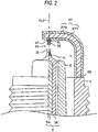
- Fig. 1 is a partially cutaway front view illustrating a spark plug 1.
- the direction of the axis CL1 of the spark plug 1 represents an up and down direction in the figure, and the lower side and the upper side represent the front end side and the rear end side of the spark plug 1.
- the spark plug 1 includes an insulator 2 which is a long insulating member, and a cylindrical metal shell 3 for holding this.
- the insulator 2 is provided with an axial hole 4 penetrating along the axis CL1.
- a center electrode 5 is inserted into and fixed to the front end portion of the axial hole 4, and a terminal electrode 6 is inserted into and fixed to the rear end portion.
- a resistor 7 is disposed between the center electrode 5 and the terminal electrode 6, and both end portions of the resistor 7 are electrically connected to the center electrode 5 and the terminal electrode 6 via conductive glass sealing layers 8 and 9, respectively.
- the center electrode 5 protrudes from the front end of the insulator 2 to be fixed thereto, and the terminal electrode 6 protrudes from the rear end of the insulator 2 to be fixed thereto.
- a precious metal tip (a precious metal tip for the center electrode) 31 containing iridium as a main component and 5 mass% of platinum is joined to the center electrode 5 by welding.
- the insulator 2 is, as is well known, formed by performing firing on aluminium and the like, and includes, from the outer appearance, a large diameter part 11 having the shape of a flange protruding outward in the radial direction substantially at the center portion of the direction of the axis CL1, an intermediate shank part 12 provided on the front end side in front of the large diameter part 11 with a smaller diameter, and a long leg part 13 provided on the front end side in front of the intermediate shank part 12 with a smaller diameter and exposed to the combustion chamber of an internal combustion engine (engine).
- the front end side of insulator 2, which includes the large diameter part 11, the intermediate shank part 12, and the long leg part 13, is accommodated in the cylindrical metal shell 3.
- a step part 14 is formed at a connection portion between the long leg part 13 and the intermediate shank part 12, and the insulator 2 is locked to the metal shell 3 with the step part 14.
- the metal shell 3 is formed of metal such as low carbon steel into a cylindrical shape, and on the outer peripheral surface, a screw part (thread) 15 needed for mounting the spark plug 1 to a cylinder head of the engine is formed.
- a seating part 16 is provided on the outer peripheral surface on the rear end side behind the screw part 15, a ring-shaped gasket 18 is insert-fitted to a screw head 17 on the rear end of the screw part 15.
- a tool engagement part 19 which has a hexagonal, cross-section and to which a tool such as a wrench is engaged to mount the metal shell 3 to the cylinder head is provided, and at the rear end portion thereof, a swage part 20 for holding the insulator 2 is provided.
- a step part 21 for locking the insulator 2 is provided on the inner peripheral surface of the metal shell 3.
- the insulator 2 is inserted from the rear end side toward the front end side of the main metal clasp 3, and fixed by swaging an opening portion of the rear end side of the metal shell 3, that is, by forming the swage part 20 in the stage where its step part 14 is locked to the step part 21 of the metal shell 3.
- An annular-shaped plate packing 22 is interposed between the step parts 14 and 21 of the insulator 2 and the metal shell 3. Accordingly, the airtightness of the combustion chamber can be maintained, and the fuel gas flowing into a gap between the long leg part 13 of the insulator 2 exposed in the combustion chamber and the inner peripheral surface of the metal shell 3 does not leak.
- annular-shaped ring members 23 and 24 are interposed between the metal shell 3 and the insulator 2 on the rear end side of the metal shell 3, a powder of talc (talcum) 25 is filled between the ring members 23 and 24. That is, the metal shell 3 holds the insulator 2 with the plate packing 22, the ring members 23 and 24, and the talc 25 interposed therebetween.
- a ground electrode 27 having a substantially L shape is joined to a front end surface 26 of the metal shell 3. That is, a base end portion of the ground electrode 27 is welded to the front end surface 26 of the metal shell 3, and a front end side thereof is bent such that a side surface of the front end side thereof faces a front end portion (a front end portion of the precious metal tip 31) of the center electrode 5.
- the ground electrode 27 is provided with a precious metal tip (a precious metal tip for the ground electrode) 32 which faces the precious metal tip 31.
- the precious metal tips 31 and 32 are aligned with the axis CL1 and the gap between the precious metal tips 31 and 32 is a spark discharge gap 33.
- the center electrode 5 is configured by an inner layer 5A made of copper or a copper alloy and an outer layer 5B made of a nickel (Ni) alloy.
- the center electrode 5 has a front end side with a small diameter, a bar shape (a column shape) in an overall view, and a flat front end surface.
- the precious metal tip 31 having a column shape is disposed to overlap therewith, and by performing laser welding, electron beam welding, or the like along the outer peripheral portion of the joining surface thereof, the precious metal tip 31 and the center electrode 5 are fused together into a fused part 41. That is, the precious metal tip 31 is fixed and joined to the center electrode 5 with the fused part 41.
- the ground electrode 27 has a double-layer structure including an inner layer 27A and an outer layer 27B.
- the outer layer 27B is made of a nickel alloy such as Inconel 600 or Inconel 601 (both are brand names).
- the inner layer 27A is made of a copper alloy that is a metal having better thermal conductivity than the nickel alloy or pure copper. Due to the existence of the inner layer 27A, it is possible to achieve an improvement in heat transfer.
- the simple two-layer structure is described, however, a three-layer structure or a multi-layer structure having four or more layers may be employed.
- the layer inside the outer layer 27B contain metal having better thermal conductivity that the outer layer 27B.
- an intermediate layer made of an alloy or pure copper may be provided inside the outer layer 27B, and an innermost layer made of pure nickel may be provided inside the intermediate layer.
- the intermediate layer and the innermost layer constitute the inner layer 27A.
- the ground electrode 27 may employ a single-layer structure made of only a nickel alloy.
- the precious metal tip 31 of the center electrode 5 mainly contains iridium
- the precious metal tip 32 of the ground electrode 27 is made of a precious metal alloy containing, for example, platinum as a main component and 20 mass% of rhodium.
- the composition thereof is only an example and not limited to the description.
- a precious metal alloy (Pt-10Ni) containing platinum as a main component and 10 mass% of nickel may be employed to enhance welds with a mounting part 51 described later which mainly contains nickel.
- the precious metal tips 31 and 32 are manufactured, for example, as follows.
- an ingot mainly containing iridium or platinum is prepared, alloy components are mixed and melted therewith to obtain the predetermined composition described above, an ingot related to the molten alloy is formed again, and thereafter, hot forging and hot rolling (groove rolling) are performed on the ingot. Thereafter, a bar-shaped material is obtained by drawing, and it is cut into predetermined lengths, thereby obtaining the columnar-shaped precious metal tips 31 and 32.
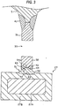
- the precious metal tip 32 on the side of the ground electrode 27 in this embodiment is not directly joined to the front end portion of the ground electrode but indirectly joined thereto with the mounting part 51 mainly containing nickel as illustrated in Fig. 3 .
- the mounting part 51 includes a base part 53 having a disc shape, and a protruding part 54 which protrudes from the base part 53 and has a columnar shape with a diameter smaller than that of the base part 53.
- a part of the base part 53 which protrudes in the outer peripheral direction from the protruding part 54 is a flange part 52.
- the precious metal tip 32 is joined to a bearing surface 54a of the protruding part 54, and the base part 53 is joined to an inner flat surface of the ground electrode 27.
- the joining order of the precious metal tip 32 and the mounting part 51 is described.
- the base part 53 of the mounting part 51 of the complex 71 is joined to the flat surface of the ground electrode 27 by resistance welding.
- both the mounting part 51 and the outer layer 27B of the ground electrode 27 are made of nickel alloys, sufficient joining strength can be obtained using resistance welding.
- welding is performed while the flange part 52 is suppressed during resistance welding, in this case, the peripheral portion (the flange part 52) of the base part 53 tends to be positively welded.
- a protrusion may be formed integrally with the lower end surface (resistance welding surface) of the base part 53 at the center position.
- the grain size of the grains of the mounting part 51 in the vicinity of the fused part 42 is greater than the grain size of the grains thereof in the vicinity of the ground electrode 27.
- the "grain size of grains” refers to the average grain size of the grains in a predetermined region.
- the value obtained through the calculation is the grain size of the grains.
- the vicinity of the fused part 42 is generally any region in which the distance to the fused part 42 is shorter than the distance to the ground electrode 27.
- a virtual circle with a diameter of 0.1 mm is to be drawn as described above, a part of the virtual circle is drawn to overlap with the fused part 42, and grains included in the circle are used for measuring the grain size.
- the vicinity of the ground electrode 27 is generally any region in which the distance to the ground electrode 27 is shorter than the distance to the fused part 42.
- a virtual circle with a diameter of 0.1 mm is to be drawn as described above, a part of the virtual circle is drawn to overlap with the ground electrode 27, and grains included in the circle are used for measuring the grain size.
- the grain size of the grains of the flange part 52 is smaller than the grain size of the grains of the protruding part 54.
- the grain size of the grains of the protruding part 54 is A ( ⁇ m) and the grain size of the grains of the flange part 52 is B ( ⁇ m)
- 10 ⁇ A ⁇ 200 , and 0.1 ⁇ B ⁇ 10 are satisfied.
- the grains of the flange part 52 are flat and oriented in a direction perpendicular to the direction (in this embodiment, the direction of the axis CL1) of the axis CL2 (see Fig. 4C ) of the mounting part 51.
- a fixed mold 62 having a mold surface 61 with the same shape as the outer appearance of the mounting part 51 is prepared.
- a pedestal tip 51A which has a columnar shape and is made of a nickel alloy is placed on the mold surface 61.
- the pedestal tip 51A has substantially the same diameter as that of the protruding part 54 and be placed and fixed to a region for forming the protruding part 54 in the mold surface 61.
- a movable mold 63 which is disposed at an interval from the fixed mold 62 is pressed in the arrow direction of the figure. Accordingly, a margin portion of the pedestal tip 51A or the like is moved (plastic deformed) in an upper outer periphery of the pedestal tip 51A and the space of the fixed mold 62 to form the flange part 52. The formed part is taken out of the fixed mold 62, thereby obtaining the mounting part 51 illustrated in Fig. 5C .
- a hammer or the like may be used as a press.
- the grains of the flange part 52 are pressed and crushed, so that the grain size thereof is smaller than the grain size of the grains of the protruding part 54 which is not crushed and deformed, and the grains thereof become flat and are oriented in the direction perpendicular to the direction (the direction of the axis CL1 after manufacturing) of the center axis.
- the grain size of the grains of the base part 53 disposed on the side of the ground electrode 27 becomes smaller than the grain size of the grains of the protruding part 54 disposed on the side of the fused part 43 after the manufacturing.
- the metal shell 3 is processed in advance. That is, a through-hole is formed on a metal material (for example, an iron-based material such as S15C or S25C or a stainless material) having a columnar shape by cold forging to form a primary shape. Thereafter, a cutting process is performed to make up the outer appearance, thereby obtaining a metal shell intermediate member.
- a metal material for example, an iron-based material such as S15C or S25C or a stainless material
- the intermediate member of the ground electrode 27 is a vertical bar-shaped member before bending.
- the ground electrode 27 before bending is obtained, for example, as follows.
- a core material made of the metal material of the inner layer 27A, and a bottomed cylindrical member made of the metal material of the outer layer 27B are prepared (neither are shown).
- a cup material is thereby formed.
- a thinning process is performed on the cup material having the two-layer structure at a cold temperature.
- examples include wire drawing using a die or the like, extrusion using a female die, and the like.
- a bar-shaped member which has a rectangular cross-section and is thinned is formed.
- the ground electrode 27 before bending, and before tip joining is joined to the front end surface of the metal shell intermediate member by resistance welding.
- an operation for removing the "shear droop" is performed.
- the ground electrode 27 before bending is joined by resistance welding after performing the swaging, cutting, and the like.
- the cutting process may be performed after performing the thinning process, joining the bar-shaped member to the metal shell intermediate member, and performing the swaging.
- the bar-shaped member joined to the front end surface thereof is introduced to a processing unit (a swaging die) of a swager from the front end side. Therefore, it is not necessary to intentionally set the bar-shaped member to be long in order to guarantee a holding portion during the swaging.
- the screw part 15 is formed at a predetermined part of the metal shell intermediate member by thread rolling. Accordingly, the metal shell 3, to which the ground electrode 27 before bending is welded, is obtained. Zinc plating or nickel plating is performed on the metal shell 3. In order to enhance corrosion resistance, chromate treatment may be additionally performed on the surface.
- the complex 71 of the precious metal tip 32 is provided. That is, in the state where the precious metal tip 32 is in contact with the bearing surface 54a of the protruding part 54 of the mounting part 51, laser welding or electron beam welding is performed thereon along the outer periphery of the joining surface thereof to form the fused part 42, and accordingly the complex 71 in which the precious metal tip 32 and the mounting part 51 are strongly joined and fixed to each other is obtained.
- the mounting part 51 (the base part 53) of the complex 71 is joined to the flat surface of the ground electrode 27 before bending by resistance welding.
- coating removal is performed on the weld portion before the welding, or masking is performed on a weld target portion during the plating.
- the welding of the complex 71 may be performed after assembling described later.
- the insulator 2 is molded.
- a base metal granulated material is prepared by using a raw powder containing alumina as a main constituent, binder, and the like, and rubber press forming is performed using the material, thereby obtaining a cylindrical compact. Grinding is performed on the obtained compact to be shaped. Then, the shaped compact is injected into a firing furnace to be fired, thereby obtaining the insulator 2.
- the center electrode 5 is prepared separately from the metal shell 3 and the insulator 2. That is, a Ni-based alloy is forged, and a copper core is provided at the center for enhancing heat dissipation. In addition, the precious metal tip 31 described above is joined by laser welding or the like to the front end portion thereof.
- the center electrode 5 to which the precious metal tip 31 obtained as described above is joined and the terminal electrode 6 are sealed and fixed in the axial hole 4 of the insulator 2 with a glass seal not shown.
- a glass seal generally, borosilicate glass and metal powder are prepared and mixed to be used.
- the prepared seal member is injected into the axial hole 4 of the insulator 2, and the terminal electrode 6 is pressed from the rear side, followed being baked by firing in the firing furnace.
- a glaze layer may be simultaneously fired on the surface of a shank part on the rear end side of the insulator 2, or a glaze layer may be formed in advance.
- the insulator 2 having the center electrode 5 and the terminal electrode 6 manufactured as described above, and the metal shell 3 having the ground electrode 27 having the vertical bar shape are assembled with each other. More specifically, cold swaging or hot swaging is performed on the rear end portion of the metal shell 3 formed to be relatively thin such that parts of the insulator 2 are held surrounding the metal shell 3 in the circumferential direction.
- ground electrode 27 having the vertical bar shape is bent to adjust the spark discharge gap 33 between (the precious metal tip 31 of) the center electrode 5 and (the precious metal tip 32 of) the ground electrode 27.
- the spark plug 1 having the above-mentioned configuration is manufactured.
- the mounting part 51 protrudes from the ground electrode 27 and is more likely to be exposed to high temperature. There is a concern that an oxide film will be formed by a combination of material that is more likely to oxidize and oxygen at the interface (see reference numeral KM shown as a thick line in Fig. 3 ) between the fused part 42 and the mounting part 51.
- the grain size of the grains of the mounting part 51, in the vicinity of the fused part 42 is greater than the grain size of the grains thereof in the vicinity of the ground electrode 27. Accordingly, in the mounting part 51 in the vicinity of the fused part 42, (the number of) pathways on which a material that is more likely to oxidize can move to the interface KM is relatively small.
- the material that is more likely to oxidize hardly appears at the interface KM from the inside of the mounting part 51, so that formation of an oxide film rarely occurs.
- the stable joining strength at the interface KM can be guaranteed for a long time, thereby preventing degradation in the exfoliation resistance of the precious metal tip 32 for the ground electrode.
- the base part 53 having the flange part 52 is provided on the side of the mounting part 51 joined to the ground electrode 27, the base part 53 having the flange part 52 is provided. Accordingly, it is possible to achieve an increase in joining area and a stronger junction. Since the heat transfer path of the precious metal tip 32 is widened, it is possible to achieve an improvement in the durability of the precious metal tip 32.
- the grain size of the grains of the flange part 52 is smaller than the grain size of the grains of the protruding part 54. Accordingly, even when a spark discharge occurs between the precious metal tip 31 for the center electrode, and the flange part 52, the grain separation is relatively small, so that damage due to the separation can be minimized.
- the grain size A of the grains of the protruding part 54 is greater than 10 ⁇ m, significant improvement in oxidation resistance can be achieved, so that it is possible to further prevent the degradation in exfoliation resistance of the precious metal tip 32. Since the grain size A of the grains of the protruding part 54 is smaller than 200 ⁇ m, a situation where the precious metal tip 32 is separated as the grains are separated rarely occurs.
- the grain size B of the grains of the flange part 52 is equal to or smaller than 10 ⁇ m, it is possible to prevent an increase in a degree of the flange part 52 consumed as the relatively larger grains are separated.
- the grain size B of the grains of the flange part 52 is equal to or greater than 0.1 ⁇ m, it is possible to prevent degradation in processability.
- the grains of the flange part 52 are flat and oriented in the direction perpendicular to the direction of the axis CL1, although a spark discharge toward the flange part 52 as described above and the grains are separated, it is possible to minimize recesses and cracks formed in the direction of the axis (the thickness direction). As a result, it is possible to prevent spark consumption resistance degradation in the mounting part 51.
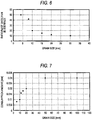
- samples which have an average grain size of 5 ⁇ m for the grains of the mounting part in the vicinity (the flange part) of the ground electrode, and different average grain sizes for the grains in the vicinity (that is, in the vicinity of the fused part: protruding part) of the precious metal tip (Pt ⁇ 10Ni) were prepared, and an oxidation resistance test was performed on each of the samples.
- a cycle for heating for two minutes at 950°C and cooling for one minute is referred to as one cycle, and the test is performed for 1000 cycles.
- a cross-section (a cross-section passing through the axis of the precious metal tip) of the weld interface between the fused part and the mounting part is observed to measure the ratio of an oxide film existing at the weld interface.
- the ratio of the oxide film is a value represented as a percent, which is obtained by performing component analysis on the weld interface (corresponding to the KM in Fig. 3 ) and dividing the total length of the weld interface by the total length of the region where the oxide is formed. The result is shown in Fig. 6 .
- the ratio of the oxide film is equal to or less than 20% and the oxide film is hardly formed.
- the ratio of the oxide film is significantly high.
- the average grain size of the grains in the protruding part is greater than 10 ⁇ m, it becomes apparent that the ratio of the oxide film is equal to or less than 20%, and an oxide film is hardly formed.
- the average size of the grains in the protruding part is smaller than 10 ⁇ m (for example, equal to or smaller than 8 ⁇ m), the ratio of the oxide film has a significantly high value.
- the average grain size of the grains in the protruding part is 200 ⁇ m, a missing part that occurs when the grains are separated is large, and there is an apparent difficulty in joining the precious metal tip.
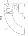
- samples which have an average grain size 15 ⁇ m for the grains of the mounting part in the vicinity (the protruding part) of the fused part and different average grain sizes for the grains in the flange part were prepared, and a desk spark endurance text was performed on each of the samples. That is, in the desk spark endurance text, a test for generating 100 spark discharges per second under a nitrogen gas atmosphere for 250 hours was performed to measure the amount (the length of the flange part consumed in the direction of the axis) of the flange part consumed before and after the test. The result is shown in Fig. 7 .
- the average grain size of the grains in the flange part is smaller than the average grain size of the grains of the mounting part in the vicinity (the protruding part) of the fused part, it is possible to prevent the consumption of the flange part.
- the case where the average grain size of the grains in the flange part is greater than the average grain size of the grains in the vicinity (the protruding part) of the fused part it becomes apparent that the consumption degree of the flange part increases. It is thought that this is because there is a possibility that the grains of the flange part of the mounting part are separated at every grain boundary due to the impact of the spark discharge, and when the grains are large, the degree of consumption due to the separation increases.
Landscapes
- Spark Plugs (AREA)
Claims (4)
- Zündkerze (1) für einen Verbrennungsmotor, umfassend:eine Mittelelektrode (5), die eine sich in Richtung einer Achse (CL1) erstreckende Stabform besitzt;einen Isolator (2), der eine im Wesentlichen zylindrische Form besitzt und auf dem Außenumfang der Mittelelektrode (5) vorgesehen ist;ein rohrförmiges Metallgehäuse (3), das auf dem Außenumfang des Isolators (2) vorgesehen ist; undeine Masseelektrode (27), die einen mit dem Metallgehäuse (3) verbundenen Basisendabschnitt und einen einem vorderen Endabschnitt der Mittelelektrode (5) gegenüberliegenden vorderen Endabschnitt besitzt,wobei eine Edelmetallspitze (32) der Masseelektrode mit dem vorderen Endabschnitt der Masseelektrode (27) an einer dem vorderen Endabschnitt der Mittelelektrode (5) gegenüberliegenden Position verbunden ist oder eine Edelmetallspitze (31) der Mittelelektrode mit dem vorderen Ende der Mittelelektrode (5) verbunden ist,wobei eine Funkenentladungsstrecke (33) zwischen dem vorderen Endabschnitt der Mittelelektrode (5) oder dem vorderen Endabschnitt der Edelmetallspitze (31) der Mittelelektrode und dem vorderen Endabschnitt der Edelmetallspitze (32) der Masseelektrode ausgebildet ist,wobei die Edelmetallspitze (32) der Masseelektrode mit einer Lagerfläche eines Befestigungsteils (51) verbunden ist, das dasselbe Bauteil wie die Masseelektrode (27) enthält, wobei ein geschmolzenes Teil (42) durch Laserschweißen oder Elektronenstrahlschweißen auf dem Metall der beiden zu verschmelzenden Teile ausgebildet ist,wobei das Befestigungsteil (51) mit der Masseelektrode (27) verbunden ist,wobei das Befestigungsteil (51) Folgendes umfasst:ein scheibenförmiges Basisteil (53) mit einer Endfläche, die mit der Masseelektrode (27) verbunden ist;ein vorspringendes Teil (54), das von der anderen Endfläche des Basisteils (53) vorspringt und eine säulenartige Form mit einem kleineren Durchmesser als das Basisteil (53) besitzt und mit dem die Edelmetallspitze (32) der Masseelektrode verbunden ist; und wobeiein Teil des Basisteils (53), der in der äußeren Umfangsrichtung von dem vorspringenden Teil (54) vorspringt, ein Flanschteil (52) ist, undwobei die Korngröße der Körner des Flanschteils (52) kleiner ist als die Korngröße der Körner des vorspringenden Teils (54);dadurch gekennzeichnet, dass
die Körner des Flanschteils (52) flach sind und in einer Richtung senkrecht zur Richtung der Achse des Befestigungsteils (51) ausgerichtet sind. - Zündkerze nach Anspruch 1, wobei Folgendes gilt:A> 10 und B≤10,wobei A (µm) die Korngröße der Körner des vorspringenden Teils (54) repräsentiert und B (µm) die Korngröße der Körner des Flanschteils (52) repräsentiert.
- Zündkerze nach Anspruch 2, wobei Folgendes gilt:10 <A≤ 200 und 0,1 ≤B≤10.
- Zündkerze nach einem der Ansprüche 1 bis 3, wobei das Befestigungsteil (51) hauptsächlich Metall enthält, das mit dem Hauptbestandteil der Masseelektrode (27) identisch ist.
Applications Claiming Priority (2)
| Application Number | Priority Date | Filing Date | Title |
|---|---|---|---|
| JP2007296453 | 2007-11-15 | ||
| PCT/JP2008/070656 WO2009063930A1 (ja) | 2007-11-15 | 2008-11-13 | 内燃機関用スパークプラグ |
Publications (3)
| Publication Number | Publication Date |
|---|---|
| EP2211432A1 EP2211432A1 (de) | 2010-07-28 |
| EP2211432A4 EP2211432A4 (de) | 2013-09-25 |
| EP2211432B1 true EP2211432B1 (de) | 2017-01-04 |
Family
ID=40638777
Family Applications (1)
| Application Number | Title | Priority Date | Filing Date |
|---|---|---|---|
| EP08848630.3A Active EP2211432B1 (de) | 2007-11-15 | 2008-11-13 | Zündkerze für einen verbrennungsmotor |
Country Status (6)
| Country | Link |
|---|---|
| US (1) | US8344604B2 (de) |
| EP (1) | EP2211432B1 (de) |
| JP (1) | JP5200013B2 (de) |
| KR (1) | KR101513325B1 (de) |
| CN (1) | CN101861685B (de) |
| WO (1) | WO2009063930A1 (de) |
Families Citing this family (11)
| Publication number | Priority date | Publication date | Assignee | Title |
|---|---|---|---|---|
| JP5396535B2 (ja) | 2010-09-24 | 2014-01-22 | 日本特殊陶業株式会社 | スパークプラグ用の電極を形成するための電極用複合体の製造方法、及びスパークプラグの製造方法 |
| JP5337188B2 (ja) | 2011-04-01 | 2013-11-06 | 日本特殊陶業株式会社 | スパークプラグの製造方法 |
| CN102611006A (zh) * | 2012-03-31 | 2012-07-25 | 株洲湘火炬火花塞有限责任公司 | 一种贵金属火花塞侧电极点火端制作方法及侧电极 |
| CN103094842A (zh) * | 2013-01-18 | 2013-05-08 | 株洲湘火炬火花塞有限责任公司 | 一种火花塞复合电极头制作方法及复合电极头带 |
| US9368943B2 (en) * | 2013-03-12 | 2016-06-14 | Federal-Mogul Ignition Company | Spark plug having multi-layer sparking component attached to ground electrode |
| JP6427133B2 (ja) * | 2016-03-29 | 2018-11-21 | 日本特殊陶業株式会社 | スパークプラグ |
| CN108123368A (zh) * | 2016-11-28 | 2018-06-05 | 霾消天蓝(北京)环保科技有限公司 | 一种火花塞 |
| JP6637452B2 (ja) | 2017-01-25 | 2020-01-29 | 日本特殊陶業株式会社 | スパークプラグ |
| DE102018101512B4 (de) | 2018-01-24 | 2020-03-19 | Federal-Mogul Ignition Gmbh | Verfahren zum Herstellen einer Elektrodenanordnung, Elektrodenanordnung und Zündkerze |
| JP7191067B2 (ja) * | 2020-08-24 | 2022-12-16 | 日本特殊陶業株式会社 | スパークプラグ |
| CN114678776B (zh) * | 2022-04-25 | 2022-12-23 | 潍柴火炬科技股份有限公司 | 一种火花塞 |
Family Cites Families (32)
| Publication number | Priority date | Publication date | Assignee | Title |
|---|---|---|---|---|
| JPS5947436B2 (ja) * | 1982-01-14 | 1984-11-19 | 株式会社デンソー | 内燃機関用スパ−クプラグ |
| US4540910A (en) * | 1982-11-22 | 1985-09-10 | Nippondenso Co., Ltd. | Spark plug for internal-combustion engine |
| JPS59160988A (ja) * | 1983-03-02 | 1984-09-11 | 日本特殊陶業株式会社 | スパ−クプラグ |
| JPS6245137A (ja) | 1985-08-23 | 1987-02-27 | Hitachi Tokyo Electron Co Ltd | 電子部品およびその製造方法 |
| US4853582A (en) * | 1987-04-06 | 1989-08-01 | Nippondenso Co., Ltd. | Spark plug for use in internal combustion engine |
| US5237197A (en) * | 1989-06-26 | 1993-08-17 | University Of Hawaii | Integrated VLSI radiation/particle detector with biased pin diodes |
| JPH03166731A (ja) | 1989-11-27 | 1991-07-18 | Hitachi Ltd | 銅又は銅合金の配線方法及び構造 |
| JP3301094B2 (ja) * | 1991-12-13 | 2002-07-15 | 株式会社デンソー | 内燃機関用スパークプラグおよびその製造方法 |
| JP3194488B2 (ja) | 1992-06-11 | 2001-07-30 | 日本特殊陶業株式会社 | スパークプラグの放電電極の製作方法 |
| US5465022A (en) * | 1992-08-12 | 1995-11-07 | Nippondenso Co., Ltd. | Spark plug for internal-combustion engine and manufacture method of the same |
| JP3562532B2 (ja) | 1994-07-26 | 2004-09-08 | 株式会社デンソー | 内燃機関用スパークプラグ |
| JP3426051B2 (ja) | 1995-04-27 | 2003-07-14 | 日本特殊陶業株式会社 | スパークプラグの製造方法 |
| US6215234B1 (en) * | 1997-12-26 | 2001-04-10 | Denso Corporation | Spark plug having specified spark gap dimensional relationships |
| US6346766B1 (en) * | 1998-05-20 | 2002-02-12 | Denso Corporation | Spark plug for internal combustion engine and method for manufacturing same |
| JP2001273966A (ja) * | 2000-01-18 | 2001-10-05 | Denso Corp | スパークプラグ |
| IT1316316B1 (it) * | 2000-02-01 | 2003-04-10 | Cit Alcatel | Metodo di protezione del traffico in reti di trasporto in fibra otticain tecnologia wdm |
| JP4213880B2 (ja) | 2000-06-30 | 2009-01-21 | 日本特殊陶業株式会社 | スパークプラグ及びその製造方法 |
| DE60102748T2 (de) * | 2000-06-30 | 2004-08-19 | NGK Spark Plug Co., Ltd., Nagoya | Zündkerze und ihr Herstellungsverfahren |
| JP4073636B2 (ja) * | 2001-02-28 | 2008-04-09 | 日本特殊陶業株式会社 | スパークプラグ及びその製造方法 |
| JP2003197346A (ja) | 2001-12-26 | 2003-07-11 | Denso Corp | スパークプラグ |
| JP4028256B2 (ja) * | 2002-02-27 | 2007-12-26 | 日本特殊陶業株式会社 | スパークプラグの製造方法 |
| JP4147152B2 (ja) * | 2002-06-21 | 2008-09-10 | 日本特殊陶業株式会社 | スパークプラグ及びスパークプラグの製造方法 |
| DE60302012T2 (de) | 2002-06-21 | 2006-07-13 | NGK Spark Plug Co., Ltd., Nagoya | Zündkerze und ihr Herstellungsverfahren |
| JP4402871B2 (ja) | 2002-10-10 | 2010-01-20 | 日本特殊陶業株式会社 | スパークプラグの製造方法 |
| US7615915B2 (en) * | 2003-09-26 | 2009-11-10 | Ngk Spark Plug Co., Ltd. | Spark plug |
| US7187110B2 (en) * | 2003-09-27 | 2007-03-06 | Ngk Spark Plug Co., Ltd. | Spark plug |
| JP2006236906A (ja) | 2005-02-28 | 2006-09-07 | Ngk Spark Plug Co Ltd | スパークプラグの製造方法 |
| JP2007044699A (ja) | 2005-08-05 | 2007-02-22 | Nissan Motor Co Ltd | 接合構造 |
| WO2007062352A2 (en) * | 2005-11-18 | 2007-05-31 | Federal-Mogul Corporation | Spark plug with multi-layer firing tip |
| KR20090033232A (ko) * | 2006-06-19 | 2009-04-01 | 페더럴-모걸 코오포레이숀 | 소직경/롱리치 스파크 플러그 |
| JP4603005B2 (ja) * | 2007-03-28 | 2010-12-22 | 日本特殊陶業株式会社 | スパークプラグの製造方法 |
| WO2009063914A1 (ja) * | 2007-11-15 | 2009-05-22 | Ngk Spark Plug Co., Ltd. | スパークプラグ |
-
2008
- 2008-11-13 US US12/743,092 patent/US8344604B2/en active Active
- 2008-11-13 CN CN2008801160710A patent/CN101861685B/zh active Active
- 2008-11-13 EP EP08848630.3A patent/EP2211432B1/de active Active
- 2008-11-13 KR KR1020107010681A patent/KR101513325B1/ko active IP Right Grant
- 2008-11-13 JP JP2009517783A patent/JP5200013B2/ja active Active
- 2008-11-13 WO PCT/JP2008/070656 patent/WO2009063930A1/ja active Application Filing
Non-Patent Citations (1)
| Title |
|---|
| None * |
Also Published As
| Publication number | Publication date |
|---|---|
| JP5200013B2 (ja) | 2013-05-15 |
| KR101513325B1 (ko) | 2015-04-17 |
| KR20100084176A (ko) | 2010-07-23 |
| EP2211432A1 (de) | 2010-07-28 |
| US20100242888A1 (en) | 2010-09-30 |
| US8344604B2 (en) | 2013-01-01 |
| CN101861685B (zh) | 2012-12-12 |
| CN101861685A (zh) | 2010-10-13 |
| EP2211432A4 (de) | 2013-09-25 |
| WO2009063930A1 (ja) | 2009-05-22 |
| JPWO2009063930A1 (ja) | 2011-03-31 |
Similar Documents
| Publication | Publication Date | Title |
|---|---|---|
| EP2211432B1 (de) | Zündkerze für einen verbrennungsmotor | |
| KR101062528B1 (ko) | 내연기관용 스파크 플러그 | |
| EP2175535B1 (de) | Zündkerze für einen verbrennungsmotor | |
| US9027524B2 (en) | Spark plug for internal combustion engine and method of manufacturing the same | |
| EP2063508B1 (de) | Zündkerze für Verbrennungsmotoren und Verfahren zur Herstellung der Zündkerze | |
| JP4912459B2 (ja) | スパークプラグ | |
| EP2020713B1 (de) | Zündkerze für Verbrennungsmotoren und Verfahren zu ihrer Herstellung | |
| EP2226911B1 (de) | Zündkerze für einen verbrennungsmotor | |
| US8624472B2 (en) | Spark plug for internal combustion engine | |
| JP4804524B2 (ja) | 内燃機関用スパークプラグ及びその製造方法 | |
| JP4954191B2 (ja) | 内燃機関用スパークプラグ及びスパークプラグの製造方法 | |
| JP4981746B2 (ja) | 内燃機関用スパークプラグ | |
| EP3073591B1 (de) | Zündkerze | |
| JP4422758B2 (ja) | 内燃機関用スパークプラグ | |
| JP4422754B2 (ja) | 内燃機関用スパークプラグ | |
| EP3068000B1 (de) | Zündkerze |
Legal Events
| Date | Code | Title | Description |
|---|---|---|---|
| PUAI | Public reference made under article 153(3) epc to a published international application that has entered the european phase |
Free format text: ORIGINAL CODE: 0009012 |
|
| 17P | Request for examination filed |
Effective date: 20100514 |
|
| AK | Designated contracting states |
Kind code of ref document: A1 Designated state(s): AT BE BG CH CY CZ DE DK EE ES FI FR GB GR HR HU IE IS IT LI LT LU LV MC MT NL NO PL PT RO SE SI SK TR |
|
| AX | Request for extension of the european patent |
Extension state: AL BA MK RS |
|
| DAX | Request for extension of the european patent (deleted) | ||
| A4 | Supplementary search report drawn up and despatched |
Effective date: 20130823 |
|
| RIC1 | Information provided on ipc code assigned before grant |
Ipc: H01T 21/02 20060101ALI20130819BHEP Ipc: H01T 13/20 20060101AFI20130819BHEP |
|
| GRAP | Despatch of communication of intention to grant a patent |
Free format text: ORIGINAL CODE: EPIDOSNIGR1 |
|
| INTG | Intention to grant announced |
Effective date: 20160718 |
|
| GRAS | Grant fee paid |
Free format text: ORIGINAL CODE: EPIDOSNIGR3 |
|
| GRAA | (expected) grant |
Free format text: ORIGINAL CODE: 0009210 |
|
| AK | Designated contracting states |
Kind code of ref document: B1 Designated state(s): AT BE BG CH CY CZ DE DK EE ES FI FR GB GR HR HU IE IS IT LI LT LU LV MC MT NL NO PL PT RO SE SI SK TR |
|
| REG | Reference to a national code |
Ref country code: GB Ref legal event code: FG4D |
|
| REG | Reference to a national code |
Ref country code: CH Ref legal event code: EP |
|
| REG | Reference to a national code |
Ref country code: AT Ref legal event code: REF Ref document number: 860103 Country of ref document: AT Kind code of ref document: T Effective date: 20170115 |
|
| REG | Reference to a national code |
Ref country code: IE Ref legal event code: FG4D |
|
| REG | Reference to a national code |
Ref country code: DE Ref legal event code: R096 Ref document number: 602008048279 Country of ref document: DE |
|
| REG | Reference to a national code |
Ref country code: LT Ref legal event code: MG4D Ref country code: NL Ref legal event code: MP Effective date: 20170104 |
|
| REG | Reference to a national code |
Ref country code: AT Ref legal event code: MK05 Ref document number: 860103 Country of ref document: AT Kind code of ref document: T Effective date: 20170104 |
|
| PG25 | Lapsed in a contracting state [announced via postgrant information from national office to epo] |
Ref country code: NL Free format text: LAPSE BECAUSE OF FAILURE TO SUBMIT A TRANSLATION OF THE DESCRIPTION OR TO PAY THE FEE WITHIN THE PRESCRIBED TIME-LIMIT Effective date: 20170104 |
|
| PG25 | Lapsed in a contracting state [announced via postgrant information from national office to epo] |
Ref country code: HR Free format text: LAPSE BECAUSE OF FAILURE TO SUBMIT A TRANSLATION OF THE DESCRIPTION OR TO PAY THE FEE WITHIN THE PRESCRIBED TIME-LIMIT Effective date: 20170104 Ref country code: GR Free format text: LAPSE BECAUSE OF FAILURE TO SUBMIT A TRANSLATION OF THE DESCRIPTION OR TO PAY THE FEE WITHIN THE PRESCRIBED TIME-LIMIT Effective date: 20170405 Ref country code: FI Free format text: LAPSE BECAUSE OF FAILURE TO SUBMIT A TRANSLATION OF THE DESCRIPTION OR TO PAY THE FEE WITHIN THE PRESCRIBED TIME-LIMIT Effective date: 20170104 Ref country code: IS Free format text: LAPSE BECAUSE OF FAILURE TO SUBMIT A TRANSLATION OF THE DESCRIPTION OR TO PAY THE FEE WITHIN THE PRESCRIBED TIME-LIMIT Effective date: 20170504 Ref country code: LT Free format text: LAPSE BECAUSE OF FAILURE TO SUBMIT A TRANSLATION OF THE DESCRIPTION OR TO PAY THE FEE WITHIN THE PRESCRIBED TIME-LIMIT Effective date: 20170104 Ref country code: NO Free format text: LAPSE BECAUSE OF FAILURE TO SUBMIT A TRANSLATION OF THE DESCRIPTION OR TO PAY THE FEE WITHIN THE PRESCRIBED TIME-LIMIT Effective date: 20170404 |
|
| PG25 | Lapsed in a contracting state [announced via postgrant information from national office to epo] |
Ref country code: PL Free format text: LAPSE BECAUSE OF FAILURE TO SUBMIT A TRANSLATION OF THE DESCRIPTION OR TO PAY THE FEE WITHIN THE PRESCRIBED TIME-LIMIT Effective date: 20170104 Ref country code: ES Free format text: LAPSE BECAUSE OF FAILURE TO SUBMIT A TRANSLATION OF THE DESCRIPTION OR TO PAY THE FEE WITHIN THE PRESCRIBED TIME-LIMIT Effective date: 20170104 Ref country code: LV Free format text: LAPSE BECAUSE OF FAILURE TO SUBMIT A TRANSLATION OF THE DESCRIPTION OR TO PAY THE FEE WITHIN THE PRESCRIBED TIME-LIMIT Effective date: 20170104 Ref country code: SE Free format text: LAPSE BECAUSE OF FAILURE TO SUBMIT A TRANSLATION OF THE DESCRIPTION OR TO PAY THE FEE WITHIN THE PRESCRIBED TIME-LIMIT Effective date: 20170104 Ref country code: BG Free format text: LAPSE BECAUSE OF FAILURE TO SUBMIT A TRANSLATION OF THE DESCRIPTION OR TO PAY THE FEE WITHIN THE PRESCRIBED TIME-LIMIT Effective date: 20170404 Ref country code: AT Free format text: LAPSE BECAUSE OF FAILURE TO SUBMIT A TRANSLATION OF THE DESCRIPTION OR TO PAY THE FEE WITHIN THE PRESCRIBED TIME-LIMIT Effective date: 20170104 Ref country code: PT Free format text: LAPSE BECAUSE OF FAILURE TO SUBMIT A TRANSLATION OF THE DESCRIPTION OR TO PAY THE FEE WITHIN THE PRESCRIBED TIME-LIMIT Effective date: 20170504 |
|
| REG | Reference to a national code |
Ref country code: DE Ref legal event code: R097 Ref document number: 602008048279 Country of ref document: DE |
|
| REG | Reference to a national code |
Ref country code: FR Ref legal event code: PLFP Year of fee payment: 10 |
|
| PG25 | Lapsed in a contracting state [announced via postgrant information from national office to epo] |
Ref country code: SK Free format text: LAPSE BECAUSE OF FAILURE TO SUBMIT A TRANSLATION OF THE DESCRIPTION OR TO PAY THE FEE WITHIN THE PRESCRIBED TIME-LIMIT Effective date: 20170104 Ref country code: IT Free format text: LAPSE BECAUSE OF FAILURE TO SUBMIT A TRANSLATION OF THE DESCRIPTION OR TO PAY THE FEE WITHIN THE PRESCRIBED TIME-LIMIT Effective date: 20170104 Ref country code: EE Free format text: LAPSE BECAUSE OF FAILURE TO SUBMIT A TRANSLATION OF THE DESCRIPTION OR TO PAY THE FEE WITHIN THE PRESCRIBED TIME-LIMIT Effective date: 20170104 Ref country code: RO Free format text: LAPSE BECAUSE OF FAILURE TO SUBMIT A TRANSLATION OF THE DESCRIPTION OR TO PAY THE FEE WITHIN THE PRESCRIBED TIME-LIMIT Effective date: 20170104 Ref country code: CZ Free format text: LAPSE BECAUSE OF FAILURE TO SUBMIT A TRANSLATION OF THE DESCRIPTION OR TO PAY THE FEE WITHIN THE PRESCRIBED TIME-LIMIT Effective date: 20170104 |
|
| PLBE | No opposition filed within time limit |
Free format text: ORIGINAL CODE: 0009261 |
|
| STAA | Information on the status of an ep patent application or granted ep patent |
Free format text: STATUS: NO OPPOSITION FILED WITHIN TIME LIMIT |
|
| PG25 | Lapsed in a contracting state [announced via postgrant information from national office to epo] |
Ref country code: DK Free format text: LAPSE BECAUSE OF FAILURE TO SUBMIT A TRANSLATION OF THE DESCRIPTION OR TO PAY THE FEE WITHIN THE PRESCRIBED TIME-LIMIT Effective date: 20170104 |
|
| 26N | No opposition filed |
Effective date: 20171005 |
|
| PG25 | Lapsed in a contracting state [announced via postgrant information from national office to epo] |
Ref country code: SI Free format text: LAPSE BECAUSE OF FAILURE TO SUBMIT A TRANSLATION OF THE DESCRIPTION OR TO PAY THE FEE WITHIN THE PRESCRIBED TIME-LIMIT Effective date: 20170104 |
|
| PG25 | Lapsed in a contracting state [announced via postgrant information from national office to epo] |
Ref country code: MC Free format text: LAPSE BECAUSE OF FAILURE TO SUBMIT A TRANSLATION OF THE DESCRIPTION OR TO PAY THE FEE WITHIN THE PRESCRIBED TIME-LIMIT Effective date: 20170104 |
|
| GBPC | Gb: european patent ceased through non-payment of renewal fee |
Effective date: 20171113 |
|
| PG25 | Lapsed in a contracting state [announced via postgrant information from national office to epo] |
Ref country code: LI Free format text: LAPSE BECAUSE OF NON-PAYMENT OF DUE FEES Effective date: 20171130 Ref country code: CH Free format text: LAPSE BECAUSE OF NON-PAYMENT OF DUE FEES Effective date: 20171130 |
|
| PG25 | Lapsed in a contracting state [announced via postgrant information from national office to epo] |
Ref country code: LU Free format text: LAPSE BECAUSE OF NON-PAYMENT OF DUE FEES Effective date: 20171113 |
|
| REG | Reference to a national code |
Ref country code: BE Ref legal event code: MM Effective date: 20171130 |
|
| REG | Reference to a national code |
Ref country code: IE Ref legal event code: MM4A |
|
| PG25 | Lapsed in a contracting state [announced via postgrant information from national office to epo] |
Ref country code: MT Free format text: LAPSE BECAUSE OF NON-PAYMENT OF DUE FEES Effective date: 20171113 |
|
| REG | Reference to a national code |
Ref country code: FR Ref legal event code: PLFP Year of fee payment: 11 |
|
| PG25 | Lapsed in a contracting state [announced via postgrant information from national office to epo] |
Ref country code: IE Free format text: LAPSE BECAUSE OF NON-PAYMENT OF DUE FEES Effective date: 20171113 |
|
| PG25 | Lapsed in a contracting state [announced via postgrant information from national office to epo] |
Ref country code: BE Free format text: LAPSE BECAUSE OF NON-PAYMENT OF DUE FEES Effective date: 20171130 Ref country code: GB Free format text: LAPSE BECAUSE OF NON-PAYMENT OF DUE FEES Effective date: 20171113 |
|
| PG25 | Lapsed in a contracting state [announced via postgrant information from national office to epo] |
Ref country code: HU Free format text: LAPSE BECAUSE OF FAILURE TO SUBMIT A TRANSLATION OF THE DESCRIPTION OR TO PAY THE FEE WITHIN THE PRESCRIBED TIME-LIMIT; INVALID AB INITIO Effective date: 20081113 |
|
| PG25 | Lapsed in a contracting state [announced via postgrant information from national office to epo] |
Ref country code: CY Free format text: LAPSE BECAUSE OF NON-PAYMENT OF DUE FEES Effective date: 20170104 |
|
| PGFP | Annual fee paid to national office [announced via postgrant information from national office to epo] |
Ref country code: FR Payment date: 20191014 Year of fee payment: 12 |
|
| PG25 | Lapsed in a contracting state [announced via postgrant information from national office to epo] |
Ref country code: TR Free format text: LAPSE BECAUSE OF FAILURE TO SUBMIT A TRANSLATION OF THE DESCRIPTION OR TO PAY THE FEE WITHIN THE PRESCRIBED TIME-LIMIT Effective date: 20170104 |
|
| PG25 | Lapsed in a contracting state [announced via postgrant information from national office to epo] |
Ref country code: FR Free format text: LAPSE BECAUSE OF NON-PAYMENT OF DUE FEES Effective date: 20201130 |
|
| P01 | Opt-out of the competence of the unified patent court (upc) registered |
Effective date: 20230512 |
|
| REG | Reference to a national code |
Ref country code: DE Ref legal event code: R081 Ref document number: 602008048279 Country of ref document: DE Owner name: NITERRA CO., LTD., NAGOYA-SHI, JP Free format text: FORMER OWNER: NGK SPARK PLUG CO., LTD., NAGOYA-SHI, AICHI, JP |
|
| PGFP | Annual fee paid to national office [announced via postgrant information from national office to epo] |
Ref country code: DE Payment date: 20230929 Year of fee payment: 16 |