EP2201239B1 - Kraftstoffpumpe, insbesondere für ein kraftstoffsystem einer kolben-brennkraftmaschine - Google Patents
Kraftstoffpumpe, insbesondere für ein kraftstoffsystem einer kolben-brennkraftmaschine Download PDFInfo
- Publication number
- EP2201239B1 EP2201239B1 EP08803453.3A EP08803453A EP2201239B1 EP 2201239 B1 EP2201239 B1 EP 2201239B1 EP 08803453 A EP08803453 A EP 08803453A EP 2201239 B1 EP2201239 B1 EP 2201239B1
- Authority
- EP
- European Patent Office
- Prior art keywords
- housing
- region
- fuel pump
- coating
- thermoplastic material
- Prior art date
- Legal status (The legal status is an assumption and is not a legal conclusion. Google has not performed a legal analysis and makes no representation as to the accuracy of the status listed.)
- Not-in-force
Links
- 239000000446 fuel Substances 0.000 title claims description 27
- 238000002485 combustion reaction Methods 0.000 title claims description 6
- 239000011248 coating agent Substances 0.000 claims description 19
- 238000000576 coating method Methods 0.000 claims description 19
- 238000007789 sealing Methods 0.000 claims description 14
- 239000012815 thermoplastic material Substances 0.000 claims description 8
- 239000011324 bead Substances 0.000 claims description 5
- 239000004696 Poly ether ether ketone Substances 0.000 claims description 2
- XAGFODPZIPBFFR-UHFFFAOYSA-N aluminium Chemical group [Al] XAGFODPZIPBFFR-UHFFFAOYSA-N 0.000 claims description 2
- 229910052782 aluminium Inorganic materials 0.000 claims description 2
- 239000000463 material Substances 0.000 claims description 2
- 229910052751 metal Inorganic materials 0.000 claims description 2
- 239000002184 metal Substances 0.000 claims description 2
- 229920002530 polyetherether ketone Polymers 0.000 claims description 2
- OKTJSMMVPCPJKN-UHFFFAOYSA-N Carbon Chemical compound [C] OKTJSMMVPCPJKN-UHFFFAOYSA-N 0.000 claims 1
- 239000004411 aluminium Substances 0.000 claims 1
- 229910052799 carbon Inorganic materials 0.000 claims 1
- 239000004033 plastic Substances 0.000 description 3
- 229920003023 plastic Polymers 0.000 description 3
- 238000011161 development Methods 0.000 description 2
- 230000018109 developmental process Effects 0.000 description 2
- 238000004519 manufacturing process Methods 0.000 description 2
- 229920001169 thermoplastic Polymers 0.000 description 2
- 239000004416 thermosoftening plastic Substances 0.000 description 2
- 229920000049 Carbon (fiber) Polymers 0.000 description 1
- 239000004917 carbon fiber Substances 0.000 description 1
- 238000005266 casting Methods 0.000 description 1
- 238000010276 construction Methods 0.000 description 1
- 230000001419 dependent effect Effects 0.000 description 1
- 239000000835 fiber Substances 0.000 description 1
- 239000002828 fuel tank Substances 0.000 description 1
- 238000003754 machining Methods 0.000 description 1
- 230000002093 peripheral effect Effects 0.000 description 1
- 239000006223 plastic coating Substances 0.000 description 1
- 239000000843 powder Substances 0.000 description 1
Images


Classifications
-
- F—MECHANICAL ENGINEERING; LIGHTING; HEATING; WEAPONS; BLASTING
- F02—COMBUSTION ENGINES; HOT-GAS OR COMBUSTION-PRODUCT ENGINE PLANTS
- F02M—SUPPLYING COMBUSTION ENGINES IN GENERAL WITH COMBUSTIBLE MIXTURES OR CONSTITUENTS THEREOF
- F02M63/00—Other fuel-injection apparatus having pertinent characteristics not provided for in groups F02M39/00 - F02M57/00 or F02M67/00; Details, component parts, or accessories of fuel-injection apparatus, not provided for in, or of interest apart from, the apparatus of groups F02M39/00 - F02M61/00 or F02M67/00; Combination of fuel pump with other devices, e.g. lubricating oil pump
- F02M63/02—Fuel-injection apparatus having several injectors fed by a common pumping element, or having several pumping elements feeding a common injector; Fuel-injection apparatus having provisions for cutting-out pumps, pumping elements, or injectors; Fuel-injection apparatus having provisions for variably interconnecting pumping elements and injectors alternatively
- F02M63/0225—Fuel-injection apparatus having a common rail feeding several injectors ; Means for varying pressure in common rails; Pumps feeding common rails
- F02M63/0265—Pumps feeding common rails
-
- F—MECHANICAL ENGINEERING; LIGHTING; HEATING; WEAPONS; BLASTING
- F02—COMBUSTION ENGINES; HOT-GAS OR COMBUSTION-PRODUCT ENGINE PLANTS
- F02M—SUPPLYING COMBUSTION ENGINES IN GENERAL WITH COMBUSTIBLE MIXTURES OR CONSTITUENTS THEREOF
- F02M59/00—Pumps specially adapted for fuel-injection and not provided for in groups F02M39/00 -F02M57/00, e.g. rotary cylinder-block type of pumps
- F02M59/02—Pumps specially adapted for fuel-injection and not provided for in groups F02M39/00 -F02M57/00, e.g. rotary cylinder-block type of pumps of reciprocating-piston or reciprocating-cylinder type
- F02M59/10—Pumps specially adapted for fuel-injection and not provided for in groups F02M39/00 -F02M57/00, e.g. rotary cylinder-block type of pumps of reciprocating-piston or reciprocating-cylinder type characterised by the piston-drive
- F02M59/102—Mechanical drive, e.g. tappets or cams
-
- F—MECHANICAL ENGINEERING; LIGHTING; HEATING; WEAPONS; BLASTING
- F02—COMBUSTION ENGINES; HOT-GAS OR COMBUSTION-PRODUCT ENGINE PLANTS
- F02M—SUPPLYING COMBUSTION ENGINES IN GENERAL WITH COMBUSTIBLE MIXTURES OR CONSTITUENTS THEREOF
- F02M59/00—Pumps specially adapted for fuel-injection and not provided for in groups F02M39/00 -F02M57/00, e.g. rotary cylinder-block type of pumps
- F02M59/44—Details, components parts, or accessories not provided for in, or of interest apart from, the apparatus of groups F02M59/02 - F02M59/42; Pumps having transducers, e.g. to measure displacement of pump rack or piston
- F02M59/445—Selection of particular materials
-
- F—MECHANICAL ENGINEERING; LIGHTING; HEATING; WEAPONS; BLASTING
- F04—POSITIVE - DISPLACEMENT MACHINES FOR LIQUIDS; PUMPS FOR LIQUIDS OR ELASTIC FLUIDS
- F04C—ROTARY-PISTON, OR OSCILLATING-PISTON, POSITIVE-DISPLACEMENT MACHINES FOR LIQUIDS; ROTARY-PISTON, OR OSCILLATING-PISTON, POSITIVE-DISPLACEMENT PUMPS
- F04C2/00—Rotary-piston machines or pumps
- F04C2/08—Rotary-piston machines or pumps of intermeshing-engagement type, i.e. with engagement of co-operating members similar to that of toothed gearing
- F04C2/12—Rotary-piston machines or pumps of intermeshing-engagement type, i.e. with engagement of co-operating members similar to that of toothed gearing of other than internal-axis type
- F04C2/14—Rotary-piston machines or pumps of intermeshing-engagement type, i.e. with engagement of co-operating members similar to that of toothed gearing of other than internal-axis type with toothed rotary pistons
-
- F—MECHANICAL ENGINEERING; LIGHTING; HEATING; WEAPONS; BLASTING
- F02—COMBUSTION ENGINES; HOT-GAS OR COMBUSTION-PRODUCT ENGINE PLANTS
- F02M—SUPPLYING COMBUSTION ENGINES IN GENERAL WITH COMBUSTIBLE MIXTURES OR CONSTITUENTS THEREOF
- F02M37/00—Apparatus or systems for feeding liquid fuel from storage containers to carburettors or fuel-injection apparatus; Arrangements for purifying liquid fuel specially adapted for, or arranged on, internal-combustion engines
- F02M37/04—Feeding by means of driven pumps
- F02M37/041—Arrangements for driving gear-type pumps
-
- F—MECHANICAL ENGINEERING; LIGHTING; HEATING; WEAPONS; BLASTING
- F02—COMBUSTION ENGINES; HOT-GAS OR COMBUSTION-PRODUCT ENGINE PLANTS
- F02M—SUPPLYING COMBUSTION ENGINES IN GENERAL WITH COMBUSTIBLE MIXTURES OR CONSTITUENTS THEREOF
- F02M37/00—Apparatus or systems for feeding liquid fuel from storage containers to carburettors or fuel-injection apparatus; Arrangements for purifying liquid fuel specially adapted for, or arranged on, internal-combustion engines
- F02M37/04—Feeding by means of driven pumps
- F02M37/045—Arrangements for driving rotary positive-displacement pumps
-
- F—MECHANICAL ENGINEERING; LIGHTING; HEATING; WEAPONS; BLASTING
- F04—POSITIVE - DISPLACEMENT MACHINES FOR LIQUIDS; PUMPS FOR LIQUIDS OR ELASTIC FLUIDS
- F04C—ROTARY-PISTON, OR OSCILLATING-PISTON, POSITIVE-DISPLACEMENT MACHINES FOR LIQUIDS; ROTARY-PISTON, OR OSCILLATING-PISTON, POSITIVE-DISPLACEMENT PUMPS
- F04C2230/00—Manufacture
- F04C2230/90—Improving properties of machine parts
- F04C2230/91—Coating
-
- F—MECHANICAL ENGINEERING; LIGHTING; HEATING; WEAPONS; BLASTING
- F05—INDEXING SCHEMES RELATING TO ENGINES OR PUMPS IN VARIOUS SUBCLASSES OF CLASSES F01-F04
- F05C—INDEXING SCHEME RELATING TO MATERIALS, MATERIAL PROPERTIES OR MATERIAL CHARACTERISTICS FOR MACHINES, ENGINES OR PUMPS OTHER THAN NON-POSITIVE-DISPLACEMENT MACHINES OR ENGINES
- F05C2201/00—Metals
- F05C2201/02—Light metals
- F05C2201/021—Aluminium
-
- F—MECHANICAL ENGINEERING; LIGHTING; HEATING; WEAPONS; BLASTING
- F05—INDEXING SCHEMES RELATING TO ENGINES OR PUMPS IN VARIOUS SUBCLASSES OF CLASSES F01-F04
- F05C—INDEXING SCHEME RELATING TO MATERIALS, MATERIAL PROPERTIES OR MATERIAL CHARACTERISTICS FOR MACHINES, ENGINES OR PUMPS OTHER THAN NON-POSITIVE-DISPLACEMENT MACHINES OR ENGINES
- F05C2225/00—Synthetic polymers, e.g. plastics; Rubber
- F05C2225/08—Thermoplastics
-
- F—MECHANICAL ENGINEERING; LIGHTING; HEATING; WEAPONS; BLASTING
- F05—INDEXING SCHEMES RELATING TO ENGINES OR PUMPS IN VARIOUS SUBCLASSES OF CLASSES F01-F04
- F05C—INDEXING SCHEME RELATING TO MATERIALS, MATERIAL PROPERTIES OR MATERIAL CHARACTERISTICS FOR MACHINES, ENGINES OR PUMPS OTHER THAN NON-POSITIVE-DISPLACEMENT MACHINES OR ENGINES
- F05C2225/00—Synthetic polymers, e.g. plastics; Rubber
- F05C2225/12—Polyetheretherketones, e.g. PEEK
-
- F—MECHANICAL ENGINEERING; LIGHTING; HEATING; WEAPONS; BLASTING
- F05—INDEXING SCHEMES RELATING TO ENGINES OR PUMPS IN VARIOUS SUBCLASSES OF CLASSES F01-F04
- F05C—INDEXING SCHEME RELATING TO MATERIALS, MATERIAL PROPERTIES OR MATERIAL CHARACTERISTICS FOR MACHINES, ENGINES OR PUMPS OTHER THAN NON-POSITIVE-DISPLACEMENT MACHINES OR ENGINES
- F05C2253/00—Other material characteristics; Treatment of material
- F05C2253/22—Reinforcements
Definitions
- the invention relates to a fuel pump, in particular for a fuel system of a piston internal combustion engine, according to the preamble of claim 1.
- Such a pump is through the US 4,781,552 A known. and discloses the preamble of claim 1.
- This pump has a housing and within the housing two gears are arranged, which abut at least indirectly on a housing portion and which rotate during operation.
- In the housing plates are arranged on both sides of the gears, against which the gears and which consist of thermoplastic material.
- the thermoplastic material may contain metal powder to improve the thermal conductivity. Due to the massive plates, the pump requires a large amount of space and is expensive to manufacture. In addition, it must be ensured that the thermoplastic material has sufficient wear resistance.
- the fuel pump according to the invention with the features of claim 1 has the advantage that it can be made easily and compact in size and that the coating of thermoplastic material has sufficient wear resistance.
- a region of the coating is designed as a sealing region which cooperates with another region of the housing.
- the plastic coating provided according to the invention fulfills a double function in such a case: In addition to the wear-reducing function, it also fulfills a sealing function.
- a separate seal, for example by an O-ring, including the associated machining as a result of introducing corresponding O-ring grooves is not required. This also simplifies the design, facilitates assembly, reduces sources of error, etc.
- the sealing region may comprise a peripheral sealing bead or a circumferential sealing lip.
- Such embodiments are easy to produce with conventional plastics, in particular with thermoplastics, and ensure reliable sealing even of high pressure differences.
- a simple production of the coating made of plastic may consist in that the coating is melted onto the housing area.
- the housing region, to which the coating is applied comprises a comparatively thin carrier sheet, which is fastened to another housing region, preferably glued thereto. This allows for specific applications, depending on the sometimes complex geometry of the housing area and / or the area to be sealed, an individual and reliable implementation of the construction.
- FIG. 1 It includes a fuel tank 12 from which a high-pressure fuel pump 14 delivers the fuel into a high-pressure fuel reservoir 16 ("rail"). To the rail 16, a plurality of injectors 18 are connected, which inject the fuel directly into them associated combustion chambers (not shown) of the internal combustion engine.
- the high-pressure fuel pump 14 includes a gear pump 15 on the low-pressure side.
- the high-pressure fuel pump may also include a vane pump or any other suitable type of pump on the low-pressure side.
- the fuel high pressure pump 14 including the low pressure side gear pump 15 is directly and mechanically driven by the engine.
- the low-pressure side gear pump may also have a separate drive, such as an electric motor.
- FIG. 2 a portion of the gear pump 15 of the high-pressure fuel pump 14 is shown, but in a state in which a housing cover existing in normal operation is removed.
- a housing 20 manufactured as a casting, which is machined at various locations and which contains the mechanical and fluidic components of the high-pressure fuel pump 14.
- the housing 20 is made of aluminum.
- a housing portion 22 is machined as a flat surface.
- the housing portion 22 serves as a running surface for two gears 24 and 26, which during operation of the high-pressure fuel pump 14th and the gear pump 15 rotate in opposite directions.
- the gears 24 and 26 are thus parts which move during operation and at least indirectly abut against the flat housing region 22.
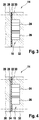
- FIG. 3 shows, on the housing portion 22, a coating of a plastic, namely applied from a thermoplastic.
- This coating is in FIG. 2
- the coating 28 is applied to the housing portion 22 on its side facing the two gears 24 and 26 side, the two gears 24 and 26 are thus applied to the coating 28.
- a polyetheretherketone is used as the material for the coating 28.
- the coating 28 is melted onto the housing region 22.
- the coating is additionally reinforced by fibers, in particular carbon fibers.
- the coating 28 outside the running surface of the two gears 24 and 26 has a circumferential sealing bead 30 which forms a sealing region which cooperates with a cover 32 designed as another area of the housing 20.
- the cover 32 is screwed to the housing portion 22, which is compressed during assembly of the sealing bead 30 and thereby the area located radially inwardly of the sealing bead 30 is sealed to the outside.
- FIG. 4 An alternative embodiment is in FIG. 4 shown. In doing so, those elements and regions which have equivalent functions to elements and regions which have already been described bear the same reference numerals. They will not be discussed again in detail.
- the housing region 22, on which the coating 28 is applied comprises a comparatively thin carrier sheet 34, which is glued to a residual housing 36 of the high-pressure fuel pump 14.
Landscapes
- Engineering & Computer Science (AREA)
- Mechanical Engineering (AREA)
- General Engineering & Computer Science (AREA)
- Chemical & Material Sciences (AREA)
- Combustion & Propulsion (AREA)
- Fuel-Injection Apparatus (AREA)
- Details And Applications Of Rotary Liquid Pumps (AREA)
- Rotary Pumps (AREA)
- Details Of Reciprocating Pumps (AREA)
Description
- Die Erfindung geht aus von einer Kraftstoffpumpe, insbesondere für ein Kraftstoffsystem einer Kolben-Brennkraftmaschine, nach der Gattung des Anspruchs 1.
- Eine solche Pumpe ist durch die
US 4 781 552 A bekannt. und offenbart den Oberbegriff des Anspruchs 1. Diese Pumpe weist ein Gehäuse auf und innerhalb des Gehäuses sind zwei Zahnräder angeordnet, die zumindest mittelbar an einem Gehäusebereich anliegen und die sich im Betrieb rotierend bewegen. Im Gehäuse sind beiderseits der Zahnräder Platten angeordnet, an denen die Zahnräder anliegen und die aus thermoplastischem Kunststoff bestehen. Der thermoplastische Kunststoff kann zur Verbesserung der Wärmeleitfähigkeit Metallpulver enthalten. Durch die massiven Platten erfordert die Pumpe einen großen Bauraum und ist aufwendig in der Herstellung. Außerdem muss sichergestellt sein, dass der thermoplastische Kunststoff eine ausreichende Verschleißfestigkeit aufweist. - Die erfindungsgemäße Kraftstoffpumpe mit den Merkmalen des Anspruchs 1 hat demgegenüber den Vorteil, dass diese einfach und mit kompakter Baugröße hergestellt werden kann und dass die Beschichtung aus thermoplastischem Kunststoff eine ausreichende Verschleißfestigkeit aufweist.
- In den abhängigen Ansprüchen sind vorteilhafte Ausgestaltungen und Weiterbildungen der erfindungsgemäßen Kraftstoffpumpe angegeben.
- Besonders vorteilhaft ist jene Weiterbildung der erfindungsgemäßen Kraftstoffpumpe, bei welcher ein Bereich der Beschichtung als Dichtbereich ausgebildet ist, der mit einem anderen Bereich des Gehäuses zusammenarbeitet. Die erfindungsgemäß vorgesehene Beschichtung aus Kunststoff erfüllt in einem solchen Falle eine Doppelfunktion: Neben der verschleißmindernden Funktion erfüllt sie noch eine Dichtungsfunktion. Eine separate Abdichtung, beispielsweise durch einen O-Ring, einschließlich der damit zusammenhängenden spanabhebenden Bearbeitung in Folge des Einbringens entsprechender O-Ring-Nuten ist somit nicht erforderlich. Auch hierdurch wird die Konstruktion vereinfacht, der Zusammenbau erleichtert, Fehlerquellen werden reduziert, etc.
- Der Dichtbereich kann einen umlaufenden Dichtwulst oder eine umlaufende Dichtlippe umfassen. Derartige Ausgestaltungen sind mit üblichen Kunststoffen, insbesondere mit Thermoplasten, leicht herstellbar und gewährleisten eine zuverlässige Abdichtung auch hoher Druckdifferenzen.
- Eine einfache Herstellung der Beschichtung aus Kunststoff kann darin bestehen, dass die Beschichtung auf den Gehäusebereich aufgeschmolzen wird.
- Möglich ist ferner, dass der Gehäusebereich, auf den die Beschichtung aufgebracht ist, ein vergleichsweise dünnes Trägerblech umfasst, welches an einem anderen Gehäusebereich befestigt, vorzugsweise mit diesem verklebt ist. Dies ermöglicht in spezifischen Anwendungsfällen, abhängig von der bisweilen komplexen Geometrie des Gehäusebereichs und/oder des abzudichtenden Bereichs, eine individuelle und zuverlässige Realisierung der Konstruktion.
- Nachfolgend werden Ausführungsformen der Erfindung unter Bezugnahme auf die Zeichnung näher erläutert. In der Zeichnung zeigen:
- Figur 1
- eine schematische Darstellung eines Kraftstoffsystem einer Kolben-Brennkraftmaschine mit einer Kraftstoff-Hochdruckpumpe;
- Figur 2
- eine perspektivische Darstellung eines Bereichs der Kraftstoff-Hochdruckpumpe von
Figur 1 ; - Figur 3
- einen schematischen Schnitt durch den in
Figur 2 dargestellten Bereich; und - Figur 4
- eine Darstellung ähnlich
Figur 3 einer alternativen Ausführungsform. - In
Figur 1 trägt ein Kraftstoffsystem für eine Kolben-Brennkraftmaschine insgesamt das Bezugszeichen 10. Es umfasst einen Kraftstoffbehälter 12, aus dem eine Kraftstoff-Hochdruckpumpe 14 den Kraftstoff in einen Hochdruck-Kraftstoffspeicher 16 ("Rail") fördert. An das Rail 16 sind mehrere Injektoren 18 angeschlossen, die den Kraftstoff direkt in ihnen zugeordnete Brennräume (nicht dargestellt) der Brennkraftmaschine einspritzen. - Die Kraftstoff-Hochdruckpumpe 14 umfasst niederdruckseitig eine Zahnradpumpe 15. In nicht dargestellten Ausführungsbeispielen kann die Kraftstoff-Hochdruckpumpe niederdruckseitig auch eine Flügelzellenpumpe oder jede andere geeignete Pumpenart umfassen. Angetrieben wird die Kraftstoff-Hochdruckpumpe 14 einschließlich der niederdruckseitigen Zahnradpumpe 15 direkt und mechanisch von der Brennkraftmaschine. In einem nicht dargestellten Ausführungsbeispiel kann die niederdruckseitige Zahnradpumpe auch über einen separaten Antrieb verfügen, beispielsweise einen Elektromotor.
- In
Figur 2 ist ein Bereich der Zahnradpumpe 15 der Kraftstoff-Hochdruckpumpe 14 dargestellt, jedoch in einem Zustand, in dem ein im normalen Betrieb vorhandener Gehäusedeckel abgenommen ist. Man erkennt ein als Gussteil hergestelltes Gehäuse 20, welches an verschiedenen Stellen spanend bearbeitet ist und welches die mechanischen und fluidischen Komponenten der Kraftstoff-Hochdruckpumpe 14 beinhaltet. Das Gehäuse 20 ist aus Aluminium hergestellt. Ein Gehäusebereich 22 ist als ebene Fläche bearbeitet. Der Gehäusebereich 22 dient als Lauffläche für zwei Zahnräder 24 und 26, die im Betrieb der Kraftstoff-Hochdruckpumpe 14 und der Zahnradpumpe 15 gegensinnig rotieren. Bei den Zahnrädern 24 und 26 handelt es sich also um sich im Betrieb bewegende Teile, die an dem ebenen Gehäusebereich 22 zumindest mittelbar anliegen. - Wie auch aus
Figur 3 hervorgeht, ist auf dem Gehäusebereich 22 eine Beschichtung aus einem Kunststoff, nämlich aus einem Thermoplast aufgebracht. Diese Beschichtung ist inFigur 2 kreuzschraffiert dargestellt, sie trägt das Bezugszeichen 28. Die Beschichtung 28 ist auf den Gehäusebereich 22 auf seiner sich zu den beiden Zahnrädern 24 und 26 gewandten Seite aufgebracht, die beiden Zahnräder 24 und 26 liegen also an der Beschichtung 28 an. Konkret wird als Werkstoff für die Beschichtung 28 ein Polyetheretherketon verwendet. Die Beschichtung 28 ist auf den Gehäusebereich 22 aufgeschmolzen. Die Beschichtung ist zusätzlich durch Fasern, insbesondere Karbonfasern, verstärkt. - Wie aus
Figur 3 hervorgeht, weist die Beschichtung 28 außerhalb der Lauffläche der beiden Zahnräder 24 und 26 einen umlaufenden Dichtwulst 30 auf, der einen Dichtbereich bildet, der mit einem als Deckel 32 ausgebildeten anderen Bereich des Gehäuses 20 zusammenarbeitet. Der Deckel 32 ist an den Gehäusebereich 22 angeschraubt, wobei bei der Montage der Dichtwulst 30 komprimiert und hierdurch der radial einwärts vom Dichtwulst 30 gelegene Bereich nach außen abgedichtet wird. - Eine alternative Ausführungsform ist in
Figur 4 gezeigt. Dabei tragen solche Elemente und Bereiche, die äquivalente Funktionen zu Elementen und Bereichen aufweisen, die bereits beschrieben worden sind, die gleichen Bezugszeichen. Auf sie wird nicht nochmals im Detail eingegangen. - Im Unterschied zu dem Ausführungsbeispiel der
Figuren 2 und3 umfasst der Gehäusebereich 22, auf dem die Beschichtung 28 aufgebracht ist, ein vergleichsweises dünnes Trägerblech 34, welches mit einem Restgehäuse 36 der Kraftstoff-Hochdruckpumpe 14 verklebt ist.
Claims (5)
- Kraftstoffpumpe (15), insbesondere für ein Kraftstoffsystem (10) einer Kolben-Brennkraftmaschine, mit einem Gehäuse (20) und mindestens einem zumindest mittelbar an einem Gehäusebereich (22) anliegenden und sich im Betrieb bewegenden Teil (24, 26), wobei der Gehäusebereich (22) einen thermoplastischen Kunststoff umfasst, dadurch gekennzeichnet, dass der thermoplastische Kunststoff als Beschichtung (28) auf den Gehäusebereich (22) auf seiner zum sich bewegenden Teil (24, 26) gewandten Seite aufgebracht ist, dass der thermoplastische Kunststoff ein Polyetheretherketon ist, dass der thermoplastische Kunststoff durch Fasern, insbesondere Karbonfasern, verstärkt ist und dass das Material mindestens des Gehäusebereichs (22), auf den die Beschichtung (28) aufgebracht ist, Aluminium umfasst oder Aluminium ist.
- Kraftstoffpumpe (15) nach Anspruch1, dadurch gekennzeichnet, dass ein Bereich der Beschichtung (28) als Dichtbereich (30) ausgebildet ist, der mit einem anderen Bereich (32) des Gehäuses (20) zusammenarbeitet.
- Kraftstoffpumpe (15) nach Anspruch 2, dadurch gekennzeichnet, dass der Dichtbereich einen umlaufenden Dichtwulst (40) oder eine umlaufende Dichtlippe umfasst.
- Kraftstoffpumpe (15) nach einem der vorhergehenden Ansprüche, dadurch gekennzeichnet, dass die Beschichtung (28) auf den Gehäusebereich (22) aufgeschmolzen ist.
- Kraftstoffpumpe (15) nach einem der vorhergehenden Ansprüche, dadurch gekennzeichnet, dass der Gehäusebereich (22), auf den die Beschichtung (28) aufgebracht ist, ein vergleichsweise dünnes Trägerblech (34) umfasst, welches an einem anderen Gehäusebereich (36) befestigt, vorzugsweise mit diesem verklebt ist.
Applications Claiming Priority (2)
| Application Number | Priority Date | Filing Date | Title |
|---|---|---|---|
| DE102007044499A DE102007044499A1 (de) | 2007-09-18 | 2007-09-18 | Kraftstoffpumpe, insbesondere für ein Kraftstoffsystem einer Kolben-Brennkraftmaschine |
| PCT/EP2008/061470 WO2009037100A1 (de) | 2007-09-18 | 2008-09-01 | Kraftstoffpumpe, insbesondere für ein kraftstoffsystem einer kolben-brennkraftmaschine |
Publications (2)
| Publication Number | Publication Date |
|---|---|
| EP2201239A1 EP2201239A1 (de) | 2010-06-30 |
| EP2201239B1 true EP2201239B1 (de) | 2017-04-12 |
Family
ID=40084320
Family Applications (1)
| Application Number | Title | Priority Date | Filing Date |
|---|---|---|---|
| EP08803453.3A Not-in-force EP2201239B1 (de) | 2007-09-18 | 2008-09-01 | Kraftstoffpumpe, insbesondere für ein kraftstoffsystem einer kolben-brennkraftmaschine |
Country Status (8)
| Country | Link |
|---|---|
| US (1) | US8261719B2 (de) |
| EP (1) | EP2201239B1 (de) |
| JP (1) | JP5232237B2 (de) |
| KR (1) | KR20100058564A (de) |
| CN (1) | CN101802386B (de) |
| DE (1) | DE102007044499A1 (de) |
| RU (1) | RU2492348C2 (de) |
| WO (1) | WO2009037100A1 (de) |
Families Citing this family (8)
| Publication number | Priority date | Publication date | Assignee | Title |
|---|---|---|---|---|
| DE102008042075A1 (de) * | 2008-09-15 | 2010-03-18 | Robert Bosch Gmbh | Vorrichtung zur Kraftstoffversorgung einer Verbrennungskraftmaschine |
| IT1396955B1 (it) * | 2009-12-18 | 2012-12-20 | Bosch Gmbh Robert | Impianto di alimentazione di carburante ad un motore a combustione interna |
| DE102010001121A1 (de) * | 2010-01-22 | 2011-07-28 | Robert Bosch GmbH, 70469 | Kraftstoffeinspritzsystem und Verfahren zum Steuern einer Kraftstoffpumpe |
| DE102010041213A1 (de) * | 2010-09-22 | 2012-03-22 | Robert Bosch Gmbh | Hochdruckpumpe und Verfahren zum Herstellen eines Pumpengehäuses |
| DE102010041425A1 (de) * | 2010-09-27 | 2012-03-29 | Robert Bosch Gmbh | Kraftstoffhochdruckpumpe |
| BR112016008459B1 (pt) | 2013-11-07 | 2023-02-07 | SpecGx LLC | Produção de morfinanos de 6-hidroxi sem isolamento de intermediários |
| GB2552328A (en) * | 2016-07-18 | 2018-01-24 | Delphi Int Operations Luxembourg Sarl | Transfer pump |
| CN111173738A (zh) * | 2018-11-12 | 2020-05-19 | 罗伯特·博世有限公司 | 叶片泵及包括叶片泵的燃料喷射系统 |
Family Cites Families (23)
| Publication number | Priority date | Publication date | Assignee | Title |
|---|---|---|---|---|
| GB683678A (en) | 1950-06-16 | 1952-12-03 | Borg Warner | Improvements in or relating to gear pumps |
| GB769763A (en) * | 1954-05-20 | 1957-03-13 | Air Equipement | Improvements in or relating to gear pumps |
| FI62712C (fi) | 1979-02-08 | 1983-02-10 | Valmet Oy | Kugghjulspump och/eller -motor |
| JPS60114286U (ja) * | 1984-01-10 | 1985-08-02 | 九州日立マクセル株式会社 | ギヤポンプ |
| US4781552A (en) * | 1985-11-27 | 1988-11-01 | Jean Malfit | High pressure hydraulic generator receiver for power transmission |
| EP0262189B1 (de) * | 1986-04-01 | 1990-05-30 | Jean Malfit | Hydraulischer hochdruckerzeuger bzw.-empfänger zur leistungsübertragung |
| CN87211905U (zh) * | 1987-08-14 | 1988-12-07 | 林可象 | 一种非润滑性液体用的新型齿轮泵 |
| IT1229927B (it) * | 1988-10-14 | 1991-09-16 | Cipelletti Alberto Cae | Pompa a palette. |
| IT1251843B (it) * | 1991-09-20 | 1995-05-26 | Nuovopignone Ind Meccaniche Ef | Pompa a trascinamento per fluidi viscosi, particolarmente adatta per la lubrificazione di ratiere e telai tessili |
| JPH0814167A (ja) * | 1994-06-27 | 1996-01-16 | Ueda Tekko:Kk | タンクローリ用ギヤポンプ |
| US5725362A (en) * | 1995-05-09 | 1998-03-10 | Xolox Corporation | Pump assembly |
| DE19528631C2 (de) | 1995-08-04 | 1998-07-23 | Bosch Gmbh Robert | Zahnradmaschine |
| DE19635164A1 (de) * | 1996-08-30 | 1998-03-05 | Bosch Gmbh Robert | Kolbenpumpe |
| JP3602354B2 (ja) * | 1998-11-24 | 2004-12-15 | 光洋精工株式会社 | ギヤポンプ |
| JP4239287B2 (ja) * | 1999-04-19 | 2009-03-18 | パナソニック株式会社 | 歯車ポンプ |
| JP3648406B2 (ja) * | 1999-06-30 | 2005-05-18 | 光洋精工株式会社 | ギヤポンプ |
| CN100449147C (zh) * | 2000-09-11 | 2009-01-07 | 济南液压泵有限责任公司 | 一种齿轮泵用具有双向轴向密封补偿作用的侧板 |
| DE10250554A1 (de) * | 2002-10-30 | 2004-05-19 | Robert Bosch Gmbh | Vorrichtung mit einem Gehäuse und mit wenigstens einem im Gehäuse angeordneten rotierenden Bauteil |
| DE10256528A1 (de) | 2002-12-04 | 2004-06-24 | Robert Bosch Gmbh | Hochdruckpumpe für eine Kraftstoffeinspritzeinrichtung einer Brennkraftmaschine |
| RU2274766C2 (ru) * | 2004-03-29 | 2006-04-20 | Общество с ограниченной ответственностью "Прана" | Насос для подачи топлива из бака к двс автомобиля, вентильный электродвигатель насоса для подачи топлива из бака к двс автомобиля, статор вентильного электродвигателя насоса для подачи топлива из бака двс автомобиля (варианты) |
| US7137793B2 (en) * | 2004-04-05 | 2006-11-21 | Peopleflo Manufacturing, Inc. | Magnetically driven gear pump |
| US8047825B2 (en) * | 2007-04-09 | 2011-11-01 | United Technologies Corporation | Fluoropolymer-containing films for use with positive-displacement fluid pumps |
| RU2342562C1 (ru) * | 2007-05-07 | 2008-12-27 | Тарханов Олег Владимирович | Вакуумный жидкостно-кольцевой насос |
-
2007
- 2007-09-18 DE DE102007044499A patent/DE102007044499A1/de not_active Withdrawn
-
2008
- 2008-09-01 CN CN200880107509.9A patent/CN101802386B/zh not_active Expired - Fee Related
- 2008-09-01 WO PCT/EP2008/061470 patent/WO2009037100A1/de not_active Ceased
- 2008-09-01 EP EP08803453.3A patent/EP2201239B1/de not_active Not-in-force
- 2008-09-01 KR KR1020107005849A patent/KR20100058564A/ko not_active Withdrawn
- 2008-09-01 RU RU2010115180/06A patent/RU2492348C2/ru not_active IP Right Cessation
- 2008-09-01 JP JP2010525297A patent/JP5232237B2/ja not_active Expired - Fee Related
- 2008-09-01 US US12/677,600 patent/US8261719B2/en not_active Expired - Fee Related
Non-Patent Citations (1)
| Title |
|---|
| None * |
Also Published As
| Publication number | Publication date |
|---|---|
| US20100192921A1 (en) | 2010-08-05 |
| JP5232237B2 (ja) | 2013-07-10 |
| EP2201239A1 (de) | 2010-06-30 |
| RU2492348C2 (ru) | 2013-09-10 |
| KR20100058564A (ko) | 2010-06-03 |
| RU2010115180A (ru) | 2011-10-27 |
| CN101802386B (zh) | 2015-05-06 |
| JP2010539385A (ja) | 2010-12-16 |
| CN101802386A (zh) | 2010-08-11 |
| US8261719B2 (en) | 2012-09-11 |
| DE102007044499A1 (de) | 2009-03-19 |
| WO2009037100A1 (de) | 2009-03-26 |
Similar Documents
| Publication | Publication Date | Title |
|---|---|---|
| EP2201239B1 (de) | Kraftstoffpumpe, insbesondere für ein kraftstoffsystem einer kolben-brennkraftmaschine | |
| EP2564070B1 (de) | Doppelkolbenspeicher | |
| EP2732164B1 (de) | Zahnringpumpe | |
| DE102009045574A1 (de) | Doppel-Innenzahnradpumpe | |
| DE20380270U1 (de) | Hydraulisches System insbesondere für Kraftfahrzeuge | |
| DE102016225922A1 (de) | Kolbenpumpe, insbesondere Kraftstoff-Hochdruckpumpe für eine Brennkraftmaschine | |
| DE102008002088A1 (de) | Kraftstoffhochdruckpumpe | |
| DE102007057503A1 (de) | Radialkolbenpumpe für ein Kraftstoffeinspritzsystem einer Brennkraftmaschine | |
| EP2331821B1 (de) | Hochdruck-radialkolbenpumpe | |
| EP3320210B1 (de) | Hydraulikaggregat | |
| DE102011089857A1 (de) | Pumpe, insbesondere Kraftstoffhochdruckpumpe für eine Kraftstoffeinspritzeinrichtung | |
| DE102019133966A1 (de) | Elektromotorisch angetriebener hydraulischer Pumpenaktor | |
| DE4214752C2 (de) | Ölpumpe | |
| EP2252795B1 (de) | Brennstoffpumpe | |
| DE102012207078A1 (de) | Zahnradmaschine mit einer Axialdichtung, die sich in den Bereich der radialen Außenoberfläche des zugeordneten Lagerkörpers erstreckt | |
| DE102011053148A1 (de) | Radialkolbenpumpe | |
| DE102011087103A1 (de) | Geberzylinder | |
| DE102010032056A1 (de) | Kolbeneinheit | |
| EP1231385B1 (de) | Vorrichtung zur Förderung von Hydrauliköl, Schmieröl oder dergleichen | |
| DE2134311A1 (de) | Förderpumpe, insbesondere Servolenkungspumpe | |
| DE102015224659A1 (de) | Zahnradpumpe für ein Abwärmerückgewinnungssystem | |
| DE102009008817A1 (de) | Handpumpe zum Pumpen von Kraftstoff | |
| WO2008058804A1 (de) | Kompressoreinheit | |
| DE10005236A1 (de) | Stellmotor mit einem Arbeitskolben, insbesondere für Fremd- und Hilfskraftlenkungen für Kraftfahrzeuge | |
| DE3623392A1 (de) | Pumpenkombination |
Legal Events
| Date | Code | Title | Description |
|---|---|---|---|
| PUAI | Public reference made under article 153(3) epc to a published international application that has entered the european phase |
Free format text: ORIGINAL CODE: 0009012 |
|
| 17P | Request for examination filed |
Effective date: 20100419 |
|
| AK | Designated contracting states |
Kind code of ref document: A1 Designated state(s): AT BE BG CH CY CZ DE DK EE ES FI FR GB GR HR HU IE IS IT LI LT LU LV MC MT NL NO PL PT RO SE SI SK TR |
|
| AX | Request for extension of the european patent |
Extension state: AL BA MK RS |
|
| DAX | Request for extension of the european patent (deleted) | ||
| RIC1 | Information provided on ipc code assigned before grant |
Ipc: F02M 59/44 20060101ALI20161103BHEP Ipc: F02M 59/10 20060101AFI20161103BHEP Ipc: F02M 37/04 20060101ALI20161103BHEP Ipc: F02M 63/02 20060101ALI20161103BHEP Ipc: F04C 2/14 20060101ALI20161103BHEP Ipc: F04C 15/00 20060101ALI20161103BHEP |
|
| GRAP | Despatch of communication of intention to grant a patent |
Free format text: ORIGINAL CODE: EPIDOSNIGR1 |
|
| INTG | Intention to grant announced |
Effective date: 20161216 |
|
| GRAS | Grant fee paid |
Free format text: ORIGINAL CODE: EPIDOSNIGR3 |
|
| GRAA | (expected) grant |
Free format text: ORIGINAL CODE: 0009210 |
|
| AK | Designated contracting states |
Kind code of ref document: B1 Designated state(s): AT BE BG CH CY CZ DE DK EE ES FI FR GB GR HR HU IE IS IT LI LT LU LV MC MT NL NO PL PT RO SE SI SK TR |
|
| REG | Reference to a national code |
Ref country code: GB Ref legal event code: FG4D Free format text: NOT ENGLISH |
|
| REG | Reference to a national code |
Ref country code: CH Ref legal event code: EP |
|
| REG | Reference to a national code |
Ref country code: IE Ref legal event code: FG4D Free format text: LANGUAGE OF EP DOCUMENT: GERMAN |
|
| REG | Reference to a national code |
Ref country code: AT Ref legal event code: REF Ref document number: 884159 Country of ref document: AT Kind code of ref document: T Effective date: 20170515 |
|
| REG | Reference to a national code |
Ref country code: DE Ref legal event code: R096 Ref document number: 502008015228 Country of ref document: DE |
|
| REG | Reference to a national code |
Ref country code: NL Ref legal event code: MP Effective date: 20170412 |
|
| REG | Reference to a national code |
Ref country code: LT Ref legal event code: MG4D |
|
| REG | Reference to a national code |
Ref country code: FR Ref legal event code: PLFP Year of fee payment: 10 |
|
| PG25 | Lapsed in a contracting state [announced via postgrant information from national office to epo] |
Ref country code: NL Free format text: LAPSE BECAUSE OF FAILURE TO SUBMIT A TRANSLATION OF THE DESCRIPTION OR TO PAY THE FEE WITHIN THE PRESCRIBED TIME-LIMIT Effective date: 20170412 |
|
| PG25 | Lapsed in a contracting state [announced via postgrant information from national office to epo] |
Ref country code: NO Free format text: LAPSE BECAUSE OF FAILURE TO SUBMIT A TRANSLATION OF THE DESCRIPTION OR TO PAY THE FEE WITHIN THE PRESCRIBED TIME-LIMIT Effective date: 20170712 Ref country code: ES Free format text: LAPSE BECAUSE OF FAILURE TO SUBMIT A TRANSLATION OF THE DESCRIPTION OR TO PAY THE FEE WITHIN THE PRESCRIBED TIME-LIMIT Effective date: 20170412 Ref country code: HR Free format text: LAPSE BECAUSE OF FAILURE TO SUBMIT A TRANSLATION OF THE DESCRIPTION OR TO PAY THE FEE WITHIN THE PRESCRIBED TIME-LIMIT Effective date: 20170412 Ref country code: FI Free format text: LAPSE BECAUSE OF FAILURE TO SUBMIT A TRANSLATION OF THE DESCRIPTION OR TO PAY THE FEE WITHIN THE PRESCRIBED TIME-LIMIT Effective date: 20170412 Ref country code: LT Free format text: LAPSE BECAUSE OF FAILURE TO SUBMIT A TRANSLATION OF THE DESCRIPTION OR TO PAY THE FEE WITHIN THE PRESCRIBED TIME-LIMIT Effective date: 20170412 Ref country code: GR Free format text: LAPSE BECAUSE OF FAILURE TO SUBMIT A TRANSLATION OF THE DESCRIPTION OR TO PAY THE FEE WITHIN THE PRESCRIBED TIME-LIMIT Effective date: 20170713 |
|
| PGFP | Annual fee paid to national office [announced via postgrant information from national office to epo] |
Ref country code: FR Payment date: 20180326 Year of fee payment: 19 |
|
| PG25 | Lapsed in a contracting state [announced via postgrant information from national office to epo] |
Ref country code: PL Free format text: LAPSE BECAUSE OF FAILURE TO SUBMIT A TRANSLATION OF THE DESCRIPTION OR TO PAY THE FEE WITHIN THE PRESCRIBED TIME-LIMIT Effective date: 20170412 Ref country code: IS Free format text: LAPSE BECAUSE OF FAILURE TO SUBMIT A TRANSLATION OF THE DESCRIPTION OR TO PAY THE FEE WITHIN THE PRESCRIBED TIME-LIMIT Effective date: 20170812 Ref country code: LV Free format text: LAPSE BECAUSE OF FAILURE TO SUBMIT A TRANSLATION OF THE DESCRIPTION OR TO PAY THE FEE WITHIN THE PRESCRIBED TIME-LIMIT Effective date: 20170412 Ref country code: BG Free format text: LAPSE BECAUSE OF FAILURE TO SUBMIT A TRANSLATION OF THE DESCRIPTION OR TO PAY THE FEE WITHIN THE PRESCRIBED TIME-LIMIT Effective date: 20170712 Ref country code: SE Free format text: LAPSE BECAUSE OF FAILURE TO SUBMIT A TRANSLATION OF THE DESCRIPTION OR TO PAY THE FEE WITHIN THE PRESCRIBED TIME-LIMIT Effective date: 20170412 |
|
| REG | Reference to a national code |
Ref country code: DE Ref legal event code: R097 Ref document number: 502008015228 Country of ref document: DE |
|
| PG25 | Lapsed in a contracting state [announced via postgrant information from national office to epo] |
Ref country code: EE Free format text: LAPSE BECAUSE OF FAILURE TO SUBMIT A TRANSLATION OF THE DESCRIPTION OR TO PAY THE FEE WITHIN THE PRESCRIBED TIME-LIMIT Effective date: 20170412 Ref country code: RO Free format text: LAPSE BECAUSE OF FAILURE TO SUBMIT A TRANSLATION OF THE DESCRIPTION OR TO PAY THE FEE WITHIN THE PRESCRIBED TIME-LIMIT Effective date: 20170412 Ref country code: CZ Free format text: LAPSE BECAUSE OF FAILURE TO SUBMIT A TRANSLATION OF THE DESCRIPTION OR TO PAY THE FEE WITHIN THE PRESCRIBED TIME-LIMIT Effective date: 20170412 Ref country code: DK Free format text: LAPSE BECAUSE OF FAILURE TO SUBMIT A TRANSLATION OF THE DESCRIPTION OR TO PAY THE FEE WITHIN THE PRESCRIBED TIME-LIMIT Effective date: 20170412 Ref country code: SK Free format text: LAPSE BECAUSE OF FAILURE TO SUBMIT A TRANSLATION OF THE DESCRIPTION OR TO PAY THE FEE WITHIN THE PRESCRIBED TIME-LIMIT Effective date: 20170412 |
|
| PLBE | No opposition filed within time limit |
Free format text: ORIGINAL CODE: 0009261 |
|
| STAA | Information on the status of an ep patent application or granted ep patent |
Free format text: STATUS: NO OPPOSITION FILED WITHIN TIME LIMIT |
|
| 26N | No opposition filed |
Effective date: 20180115 |
|
| REG | Reference to a national code |
Ref country code: CH Ref legal event code: PL |
|
| GBPC | Gb: european patent ceased through non-payment of renewal fee |
Effective date: 20170901 |
|
| PG25 | Lapsed in a contracting state [announced via postgrant information from national office to epo] |
Ref country code: MC Free format text: LAPSE BECAUSE OF FAILURE TO SUBMIT A TRANSLATION OF THE DESCRIPTION OR TO PAY THE FEE WITHIN THE PRESCRIBED TIME-LIMIT Effective date: 20170412 Ref country code: SI Free format text: LAPSE BECAUSE OF FAILURE TO SUBMIT A TRANSLATION OF THE DESCRIPTION OR TO PAY THE FEE WITHIN THE PRESCRIBED TIME-LIMIT Effective date: 20170412 |
|
| REG | Reference to a national code |
Ref country code: IE Ref legal event code: MM4A |
|
| REG | Reference to a national code |
Ref country code: BE Ref legal event code: MM Effective date: 20170930 |
|
| PG25 | Lapsed in a contracting state [announced via postgrant information from national office to epo] |
Ref country code: LU Free format text: LAPSE BECAUSE OF NON-PAYMENT OF DUE FEES Effective date: 20170901 |
|
| PG25 | Lapsed in a contracting state [announced via postgrant information from national office to epo] |
Ref country code: LI Free format text: LAPSE BECAUSE OF NON-PAYMENT OF DUE FEES Effective date: 20170930 Ref country code: CH Free format text: LAPSE BECAUSE OF NON-PAYMENT OF DUE FEES Effective date: 20170930 Ref country code: GB Free format text: LAPSE BECAUSE OF NON-PAYMENT OF DUE FEES Effective date: 20170901 Ref country code: IE Free format text: LAPSE BECAUSE OF NON-PAYMENT OF DUE FEES Effective date: 20170901 |
|
| PG25 | Lapsed in a contracting state [announced via postgrant information from national office to epo] |
Ref country code: BE Free format text: LAPSE BECAUSE OF NON-PAYMENT OF DUE FEES Effective date: 20170930 |
|
| REG | Reference to a national code |
Ref country code: FR Ref legal event code: PLFP Year of fee payment: 11 |
|
| PG25 | Lapsed in a contracting state [announced via postgrant information from national office to epo] |
Ref country code: MT Free format text: LAPSE BECAUSE OF FAILURE TO SUBMIT A TRANSLATION OF THE DESCRIPTION OR TO PAY THE FEE WITHIN THE PRESCRIBED TIME-LIMIT Effective date: 20170412 |
|
| REG | Reference to a national code |
Ref country code: AT Ref legal event code: MM01 Ref document number: 884159 Country of ref document: AT Kind code of ref document: T Effective date: 20170901 |
|
| PG25 | Lapsed in a contracting state [announced via postgrant information from national office to epo] |
Ref country code: AT Free format text: LAPSE BECAUSE OF NON-PAYMENT OF DUE FEES Effective date: 20170901 |
|
| PGFP | Annual fee paid to national office [announced via postgrant information from national office to epo] |
Ref country code: DE Payment date: 20181121 Year of fee payment: 11 |
|
| PG25 | Lapsed in a contracting state [announced via postgrant information from national office to epo] |
Ref country code: HU Free format text: LAPSE BECAUSE OF FAILURE TO SUBMIT A TRANSLATION OF THE DESCRIPTION OR TO PAY THE FEE WITHIN THE PRESCRIBED TIME-LIMIT; INVALID AB INITIO Effective date: 20080901 |
|
| PG25 | Lapsed in a contracting state [announced via postgrant information from national office to epo] |
Ref country code: IT Free format text: LAPSE BECAUSE OF NON-PAYMENT OF DUE FEES Effective date: 20180901 |
|
| PG25 | Lapsed in a contracting state [announced via postgrant information from national office to epo] |
Ref country code: CY Free format text: LAPSE BECAUSE OF NON-PAYMENT OF DUE FEES Effective date: 20170412 |
|
| PG25 | Lapsed in a contracting state [announced via postgrant information from national office to epo] |
Ref country code: TR Free format text: LAPSE BECAUSE OF FAILURE TO SUBMIT A TRANSLATION OF THE DESCRIPTION OR TO PAY THE FEE WITHIN THE PRESCRIBED TIME-LIMIT Effective date: 20170412 |
|
| REG | Reference to a national code |
Ref country code: DE Ref legal event code: R119 Ref document number: 502008015228 Country of ref document: DE |
|
| PG25 | Lapsed in a contracting state [announced via postgrant information from national office to epo] |
Ref country code: PT Free format text: LAPSE BECAUSE OF FAILURE TO SUBMIT A TRANSLATION OF THE DESCRIPTION OR TO PAY THE FEE WITHIN THE PRESCRIBED TIME-LIMIT Effective date: 20170412 |
|
| PG25 | Lapsed in a contracting state [announced via postgrant information from national office to epo] |
Ref country code: DE Free format text: LAPSE BECAUSE OF NON-PAYMENT OF DUE FEES Effective date: 20200401 |
|
| PG25 | Lapsed in a contracting state [announced via postgrant information from national office to epo] |
Ref country code: FR Free format text: LAPSE BECAUSE OF NON-PAYMENT OF DUE FEES Effective date: 20190930 |