EP2199698A1 - Klimaanlage - Google Patents
Klimaanlage Download PDFInfo
- Publication number
- EP2199698A1 EP2199698A1 EP08828351A EP08828351A EP2199698A1 EP 2199698 A1 EP2199698 A1 EP 2199698A1 EP 08828351 A EP08828351 A EP 08828351A EP 08828351 A EP08828351 A EP 08828351A EP 2199698 A1 EP2199698 A1 EP 2199698A1
- Authority
- EP
- European Patent Office
- Prior art keywords
- adapter
- monitoring
- connection device
- type information
- configuration
- Prior art date
- Legal status (The legal status is an assumption and is not a legal conclusion. Google has not performed a legal analysis and makes no representation as to the accuracy of the status listed.)
- Withdrawn
Links
- 238000004378 air conditioning Methods 0.000 title claims abstract description 48
- 238000012544 monitoring process Methods 0.000 claims abstract description 62
- 238000004891 communication Methods 0.000 claims abstract description 43
- 238000012806 monitoring device Methods 0.000 claims abstract description 38
- 239000003507 refrigerant Substances 0.000 description 16
- 238000012360 testing method Methods 0.000 description 12
- 238000010586 diagram Methods 0.000 description 6
- 238000012545 processing Methods 0.000 description 6
- 230000002596 correlated effect Effects 0.000 description 3
- 230000000875 corresponding effect Effects 0.000 description 3
- 230000000694 effects Effects 0.000 description 3
- 238000012986 modification Methods 0.000 description 3
- 230000004048 modification Effects 0.000 description 3
- 230000005540 biological transmission Effects 0.000 description 2
- 238000001816 cooling Methods 0.000 description 2
- 238000010438 heat treatment Methods 0.000 description 2
Images



Classifications
-
- F—MECHANICAL ENGINEERING; LIGHTING; HEATING; WEAPONS; BLASTING
- F24—HEATING; RANGES; VENTILATING
- F24F—AIR-CONDITIONING; AIR-HUMIDIFICATION; VENTILATION; USE OF AIR CURRENTS FOR SCREENING
- F24F11/00—Control or safety arrangements
- F24F11/50—Control or safety arrangements characterised by user interfaces or communication
- F24F11/54—Control or safety arrangements characterised by user interfaces or communication using one central controller connected to several sub-controllers
-
- F—MECHANICAL ENGINEERING; LIGHTING; HEATING; WEAPONS; BLASTING
- F24—HEATING; RANGES; VENTILATING
- F24F—AIR-CONDITIONING; AIR-HUMIDIFICATION; VENTILATION; USE OF AIR CURRENTS FOR SCREENING
- F24F11/00—Control or safety arrangements
- F24F11/30—Control or safety arrangements for purposes related to the operation of the system, e.g. for safety or monitoring
-
- F—MECHANICAL ENGINEERING; LIGHTING; HEATING; WEAPONS; BLASTING
- F24—HEATING; RANGES; VENTILATING
- F24F—AIR-CONDITIONING; AIR-HUMIDIFICATION; VENTILATION; USE OF AIR CURRENTS FOR SCREENING
- F24F11/00—Control or safety arrangements
- F24F11/30—Control or safety arrangements for purposes related to the operation of the system, e.g. for safety or monitoring
- F24F11/32—Responding to malfunctions or emergencies
-
- H—ELECTRICITY
- H04—ELECTRIC COMMUNICATION TECHNIQUE
- H04Q—SELECTING
- H04Q9/00—Arrangements in telecontrol or telemetry systems for selectively calling a substation from a main station, in which substation desired apparatus is selected for applying a control signal thereto or for obtaining measured values therefrom
-
- H—ELECTRICITY
- H04—ELECTRIC COMMUNICATION TECHNIQUE
- H04Q—SELECTING
- H04Q9/00—Arrangements in telecontrol or telemetry systems for selectively calling a substation from a main station, in which substation desired apparatus is selected for applying a control signal thereto or for obtaining measured values therefrom
- H04Q9/02—Automatically-operated arrangements
-
- F—MECHANICAL ENGINEERING; LIGHTING; HEATING; WEAPONS; BLASTING
- F24—HEATING; RANGES; VENTILATING
- F24F—AIR-CONDITIONING; AIR-HUMIDIFICATION; VENTILATION; USE OF AIR CURRENTS FOR SCREENING
- F24F11/00—Control or safety arrangements
- F24F11/50—Control or safety arrangements characterised by user interfaces or communication
- F24F11/52—Indication arrangements, e.g. displays
-
- F—MECHANICAL ENGINEERING; LIGHTING; HEATING; WEAPONS; BLASTING
- F24—HEATING; RANGES; VENTILATING
- F24F—AIR-CONDITIONING; AIR-HUMIDIFICATION; VENTILATION; USE OF AIR CURRENTS FOR SCREENING
- F24F11/00—Control or safety arrangements
- F24F11/50—Control or safety arrangements characterised by user interfaces or communication
- F24F11/56—Remote control
- F24F11/58—Remote control using Internet communication
-
- H—ELECTRICITY
- H04—ELECTRIC COMMUNICATION TECHNIQUE
- H04Q—SELECTING
- H04Q2209/00—Arrangements in telecontrol or telemetry systems
- H04Q2209/10—Arrangements in telecontrol or telemetry systems using a centralized architecture
-
- H—ELECTRICITY
- H04—ELECTRIC COMMUNICATION TECHNIQUE
- H04Q—SELECTING
- H04Q2209/00—Arrangements in telecontrol or telemetry systems
- H04Q2209/70—Arrangements in the main station, i.e. central controller
- H04Q2209/75—Arrangements in the main station, i.e. central controller by polling or interrogating the sub-stations
- H04Q2209/753—Arrangements in the main station, i.e. central controller by polling or interrogating the sub-stations where the polling of the sub-stations is synchronous
Definitions
- the present invention relates to an air conditioning system for performing monitoring of devices.
- a data transmission request instruction is sent from a host monitoring device to the air conditioning devices.
- the present invention has been made in view of the aforementioned point, and it is an object of the present invention to provide an air conditioning system where a monitoring device is capable of monitoring configuration information even when there is no request from the monitoring device.
- An air conditioning system pertaining to a first aspect of the present invention comprises a device group monitoring target, a connection device and a monitoring device.
- the device group monitoring target includes one or plural indoor units and an outdoor unit.
- the connection device is communicably connected to all of the indoor unit/units and the outdoor unit configuring the device group monitoring target and has a unique ID.
- the monitoring device is communicably connected to the connection device and has a monitoring memory that stores data received from the connection device. Additionally, when power supply is started, the connection device performs communication with all of the indoor unit/units and the outdoor unit to collect configuration type information representing at least one of the configuration and the type of the device group monitoring target and transmits the configuration type information to the monitoring device together with the ID of the connection device.
- processing to establish a correlation between the configuration type information and the ID of the connection device may be performed by the connection device or may be performed by the monitoring device.
- the connection device performs communication with all of the indoor unit/units and the outdoor unit mentioned here, not only is there included a case where the connection device simply performs communication with the individual indoor unit/units and outdoor unit respectively, but there is also included a case where, for example, the connection device performs, via a certain outdoor unit, communication with that outdoor unit and plural indoor units configuring a refrigerant circuit.
- connection device uses as a trigger a situation where it receives power supply to perform communication with all of the indoor unit/units and the outdoor unit included in the device group monitoring target connected to the connection device, collect configuration type information, and transmit the configuration type information to the monitoring device together with the ID of the connection device.
- the monitoring device grasp, even without the monitoring device having to actively collect device configuration information, the most recent information in regard to at least any of the configuration and the type resulting from all of the indoor unit/units and the outdoor unit included in the device group monitoring target communicably connected to the connection device each time power is supplied to the connection device.
- An air conditioning system pertaining to a second aspect of the present invention is the air conditioning system of the first aspect of the invention, wherein one of the connection devices is disposed with respect to one of the device group monitoring targets.
- the device group monitoring target and the connection device correspond to each other on a one-to-one basis.
- the monitoring device can continue management as is at a point in time prior to the fault or the like by referencing the ID of the connection device.
- An air conditioning system pertaining to a third aspect of the present invention is the air conditioning system of the first or second aspect of the invention, wherein the monitoring memory establishes a correspondence between and stores the configuration type information and the ID of the connection device. Additionally, the monitoring device overwrites the configuration type information stored in the monitoring memory in correspondence with the ID of the connection device each time the monitoring device receives the configuration type information and the ID of the connection device from the connection device.
- the configuration type information is overwritten in the monitoring memory each time, so it becomes possible for the monitoring device to monitor the most recent information.
- An air conditioning system pertaining to a fourth aspect of the present invention is the air conditioning system of any of the first to third aspects of the invention, wherein the connection device is built into the device group monitoring target.
- connection device is built into the device group monitoring target together with the indoor unit/units and the outdoor unit, so the configuration can be simplified.
- An air conditioning system pertaining to a fifth aspect of the present invention comprises a device group monitoring target, a connection device and a monitoring device.
- the device group monitoring target includes one or plural indoor units and an outdoor unit.
- the connection device is connected to, so as to be capable of maintaining a state of communication with, all of the indoor unit/units and the outdoor unit and has a unique ID.
- the monitoring device is communicably connected to the connection device and has a monitoring memory that stores data received from the connection device. Additionally, when communication with at least any one of the indoor unit/units and the outdoor unit becomes unestablished, the connection device collects configuration type information representing at least one of the configuration and the type of the device group monitoring target communicably connected to the connection device and transmits the configuration type information to the monitoring device together with the ID of the connection device.
- processing to establish a correlation between the configuration type information and the ID of the connection device may be performed by the connection device or may be performed by the monitoring device.
- the connection device performs communication with all of the indoor unit/units and the outdoor unit mentioned here, not only is there included a case where the connection device simply performs communication with the individual indoor unit/units and outdoor unit respectively, but there is also included a case where, for example, the connection device performs, via a certain outdoor unit, communication with that outdoor unit and plural indoor units configuring a refrigerant circuit.
- connection device uses as a trigger a situation where communication with at least any one of the indoor unit/units and the outdoor unit becomes unestablished to collect configuration type information in regard to the device group monitoring target communicably connected to the connection device and transmit the configuration type information to the monitoring device together with the ID of the connection device.
- the monitoring device grasp, even without the monitoring device having to actively collect device configuration information, the most recent information in regard to at least any of the configuration and the type resulting from all of the indoor unit/units and the outdoor unit included in the device group monitoring target communicably connected to the connection device each time there arises a device where communication with the connection device becomes unestablished.
- the monitoring device grasp, even without the monitoring device having to actively collect device configuration information, the most recent information in regard to at least any of the configuration and the type resulting from all of the indoor unit/units and the outdoor unit included in the device group monitoring target communicably connected to the connection device each time power is supplied to the connection device.
- the monitoring device even when a fault or the like in the device group monitoring target is repaired and the device group monitoring target is restored to a state prior to the fault, it becomes possible for the monitoring device to continue management as is at a point in time prior to the fault or the like by referencing the ID of the connection device.
- the configuration type information is overwritten in the monitoring memory each time, so it becomes possible for the monitoring device to monitor the most recent information.
- the configuration can be simplified.
- the monitoring device it becomes possible for the monitoring device to automatically perform grasping of changes in the configuration type information without having to actively collect device configuration information.
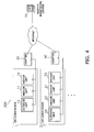
- FIG 1 shows a general configuration diagram of an air conditioning system 100 in which an embodiment of the present invention is employed.
- the air conditioning system 100 is a system that remotely performs monitoring and management of air conditioners 1 and 2 that are control targets and is equipped with a remote monitoring center 70 and the air conditioners 1 and 2.
- the remote monitoring center 70 is communicably connected to an adapter 30 of the air conditioner 1 and an adapter 40 of the air conditioner 2 via the Internet respectively.
- the air conditioner 1 has the adapter 30, one outdoor unit 12 and two indoor units 10 and 11 and is a device group monitoring target that is monitored and managed by the remote monitoring center 70.
- the two indoor units 10 and 11 are respectively connected by a refrigerant pipe to, and cooperate with, the outdoor unit 12, whereby one refrigerant system is configured by the device group comprising these three devices.
- the adapter 30 is communicably connected via a local network to the outdoor unit 12 and the indoor units 10 and 11.
- the air conditioner 2 has the adapter 40, one outdoor unit 23 and three indoor units 20, 21 and 22 and is a device group monitoring target that is monitored and managed by the remote monitoring center 70.
- the three indoor units 20, 21 and 22 are respectively connected by a refrigerant pipe to, and cooperate with, the outdoor unit 23, whereby one refrigerant system that is separate from that of the aforementioned air conditioner 1 is configured by the device group comprising these four devices.
- the adapter 40 is communicably connected via a local network to the outdoor unit 23 and the indoor units 20, 21 and 22.
- the air conditioner 2 there is employed a system configuration where one more indoor unit than in the refrigerant system of the air conditioner 1 is connected as a result of the three indoor units 20, 21 and 22 being connected to the one outdoor unit 23.
- FIG 2 shows a functional block configuration diagram of the air conditioning system 100.
- an outdoor control unit 12C built into the outdoor unit 12 an indoor control unit 10C built into the indoor unit 10, an indoor control unit 11C built into the indoor unit 11 and the adapter 30 are communicably interconnected via a local network.
- the adapter 30 has a CPU 31, an adapter memory 32 and a communication unit 39.
- the indoor control units 10C, 11C and the outdoor control unit 12C receive control commands from the CPU 31 of the adapter 30 and drive and control each component. For example, there are control items such as cooling operation, heating operation, setting temperature, air volume, and air direction. Further, a unique first adapter ID 33 is given beforehand to the adapter 30 and stored in the adapter memory 32.
- This adapter memory 32 stores system configuration data 34 and first model number data 35 of the refrigerant system of the air conditioner 1 that are acquired by communication with the indoor control units 10C, 11C and the outdoor control unit 12C.
- the system configuration data 34 are configuration information of each device configuring the air conditioner 1 and here are information representing that the refrigerant system configuration is one where the two indoor units 10 and 11 are connected with respect to the one outdoor unit 12.
- the first model number data 35 are information representing model numbers corresponding to the models, serial numbers and the like of the outdoor unit 12 and the indoor units 10 and 11 configuring the air conditioner 1.
- an unillustrated controller is disposed in the air conditioner 1, such that the user can operate this controller to input predetermined instructions. For example, the user can operate the controller to input an instruction to perform test operation or the like.
- the adapter 30 is built into the air conditioner 1, the configuration can be simplified over a case where the adapter is given a separate configuration.
- the air conditioner 2 has substantially the same configuration as that of the air conditioner 1, and an outdoor control unit 23C built into the outdoor unit 23, an indoor control unit 20C built into the indoor unit 20, an indoor control unit 21C built into the indoor unit 21, an indoor control unit 22C built into the indoor unit 22 and the adapter 40 are communicably interconnected via a local network.
- the adapter 40 has a CPU 41, an adapter memory 42 and a communication unit 49.
- the indoor control units 20C, 21C and 22C and the outdoor control unit 23C receive control commands from the CPU 41 of the adapter 40 and drive and control each component. Control here is the same as in the air conditioner 1; for example, there are control items such as cooling operation, heating operation, setting temperature, air volume, and air direction.
- a unique second adapter ID 43 that is separate from the first adapter ID 33 is given beforehand to the adapter 40 and stored in the adapter memory 42.
- This adapter memory 42 stores system configuration data 44 and second model number data 45 of the refrigerant system of the air conditioner 2 that are acquired by communication with the indoor control units 20C, 21C and 22C and the outdoor control unit 23C.
- the system configuration data 44 are, similar to those of the air conditioner 1, configuration information of each device configuring the air conditioner 2 and here are information representing that the refrigerant system configuration is one where the three indoor units 20, 21 and 22 are connected with respect to the one outdoor unit 23.
- the second model number data 45 are information representing model numbers corresponding to the models, serial numbers and the like of the outdoor unit 23 and the indoor units 20, 21 and 22 configuring the air conditioner 2.
- an unillustrated controller is disposed in the air conditioner 2, such that the user can operate this controller to input predetermined instructions. For example, the user can operate the controller to input an instruction to perform test operation or the like.
- the adapter 40 is built into the air conditioner 2, the configuration can be simplified over a case where the adapter is given a separate configuration.
- the remote monitoring center 70 is a device for remotely monitoring and managing the air conditioner 1 and the air conditioner 2 by communication via the Internet and is equipped with a CPU 71, a display 72, a browser 73, a center memory 74 and a communication unit 79.
- the center memory 74 there is stored a device management table 75 in which data that the communication unit 79 acquires from each of the air conditioners 1 and 2 by performing communication with the communication units 39 and 49 of each of the adapters 30 and 40 of the air conditioners 1 and 2 via the Internet are organized separately by the first adapter ID 33 and the second adapter ID 43.
- the CPU 71 starts up the browser 73 on the basis of the device management table 75 stored in this center memory 74 to display on and output to the display 72 data for monitoring and for management.
- the device management table 75 has integrated ID data 76, integrated system configuration data 77 and integrated model number data 78.
- the integrated ID data 76 are data for distinguishing the data of each of the air conditioners 1 and 2 in accordance with the first adapter ID 33 and the second adapter ID 43 in order to perform monitoring and management in which the systems of the air conditioners 1 and 2 corresponding to each of the adapters 30 and 40 are clearly distinguished on the basis of respective IDs of each of the first adapter ID 33 and the second adapter ID 43 allocated beforehand with respect to the adapters 30 and 40 of each of the air conditioners 1 and 2.
- the integrated system configuration data 77 are data in which information representing the configuration data of the refrigerant systems of each of the air conditioners 1 and 2 is organized.
- the integrated model number data 78 are data in which information representing the model numbers of the components of each of the air conditioners 1 and 2 is organized.
- the integrated system configuration data 77 and the integrated model number data 78 are correlated with the aforementioned integrated ID data 76 and stored in the center memory 74.
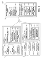
- FIG 3 shows a flowchart of monitoring/management that the air conditioning system 100 performs.
- Processing for management/monitoring that this air conditioning system 100 performs is processing that performs monitoring/management of the air conditioners 1 and 2 at a predetermined timing-for example, at the time of startup when power is applied or at the time of test operation-as a result of each of the air conditioners 1 and 2 independently transmitting their own system configuration data and model number data to the remote monitoring center 70 and the remote monitoring center 70 continuing to accumulate these data.
- each of the air conditioners 1 and 2 judges whether or not power is being supplied to it. Specifically, it is judged whether or not the adapters 30 and 40 of each of the air conditioners 1 and 2 are receiving power supply.
- the air conditioner 1 or the air conditioner 2 moves to step S12 when it judges that the CPU 31 or 41 of the adapter 30 or 40 is receiving power supply.
- FIG 3 simply shows a flowchart without dividing it into the air conditioner 1 and the air conditioner 2 (the same is true below).
- step S12 each of the air conditioners 1 and 2 judges whether or not an instruction to perform test operation has been inputted from the controller.
- the air conditioner 1 or the air conditioner 2 moves to step S 13 when it judges that the CPU 31 or 41 of the adapter 30 or 40 has received an instruction to perform test operation.
- step S 13 the CPU 31 of the adapter 30 that is receiving power supply and starts test operation performs, by the communication unit 39, communication with all of the control units (the outdoor control unit 12C and the indoor control units 10C and 11C) to which it is connected to make an inquiry with respect to all of the connected devices as to the connection status in order to check the system configuration of the air conditioner (the air conditioner 1) to which it belongs.
- the control units the outdoor control unit 12C and the indoor control units 10C and 11C
- the CPU 41 of the adapter 40 that is receiving power supply and starts test operation also similarly performs, by the communication unit 49, communication with all of the control units (the outdoor control unit 23C and the indoor control units 20C, 21C and 22C) to which it is connected to make an inquiry with respect to all of the connected devices as to the connection status in order to check the system configuration of the air conditioner (the air conditioner 2) to which it belongs.
- the control units the outdoor control unit 23C and the indoor control units 20C, 21C and 22C
- step S 14 in regard to the air conditioner 1, the communication unit 39 of the adapter 30 receives replies from the outdoor control unit 12C and the indoor control units 10C and 11C that belong to its refrigerant system and are connected to it. Then, the CPU 31 uses these received data to create, and store in the adapter memory 32, the first system configuration data 34 configuring the refrigerant system of the air conditioner 1. Further, the CPU 31 uses the data that the communication unit 39 of the adapter 30 has received by communication with each of these configuration devices to create, and store in the adapter memory 32, the first model number data 35 in regard to each of the components of the air conditioner 1.
- the communication unit 49 of the adapter 40 receives replies from the outdoor control unit 23C and the indoor control units 20C, 21C and 22C that belong to its refrigerant system and are connected to it. Then, the CPU 41 uses these received data to create, and store in the adapter memory 42, the second system configuration data 44 configuring the refrigerant system of the air conditioner 2. Further, the CPU 41 uses the data that the communication unit 49 of the adapter 40 has received by communication with each of these configuration devices to create, and store in the adapter memory 42, the second model number data 45 in regard to each of the components of the air conditioner 2.
- step S 15 in regard to the air conditioner 1, the communication unit 39 of the adapter 30 correlates, with the first adapter ID allocated beforehand to the adapter 30, the first system configuration data 34 and the first model number data 35 stored in the adapter memory 32 and transmits the first system configuration data 34 and the first model number data 35 together with the first adapter ID via the Internet to the remote monitoring center 70.
- the communication unit 49 of the adapter 40 correlates, with the second adapter ID allocated beforehand to the adapter 40, the second system configuration data 44 and the second model number data 45 stored in the adapter memory 42 and transmits the second system configuration data 44 and the second model number data 45 together with the second adapter ID via the Internet to the remote monitoring center 70.
- step S 16 the CPU 71 of the remote monitoring center 70 uses the data received from the adapters 30 and 40 of each of the air conditioners 1 and 2 to create the device management table 75 per adapter ID while distinguishing the data with which the adapter IDs of each of the adapters 30 and 40 have been correlated, stores the device management table 75 in the center memory 74, and continues accumulating data.
- the CPU 71 starts up the browser 73 on the basis of the device management table 75 stored in this center memory 74 to cause the data to be displayed on and outputted to the display 72 and performs remote monitoring and management.
- the above processing can always monitor the most recent information because the device management table 75 continues to be overwritten and updated on the basis of the adapter IDs each time there is power supply and test operation is performed.
- the present invention is not limited to this and may also be configured such that, for example, the adapter 30 uses as a trigger (the CPU 31 detects) a situation where the state of communication with any of the indoor control units 10C, 11C and the outdoor control unit 12C connected via a communication line to the adapter 30 ceases and communication becomes unestablished and such that the adapter 30 correlates, with the first adapter ID allocated beforehand to the adapter 30, the first system configuration data 34 and the first model number data 35 in regard to a target where communication with the adapter 30 is established and transmits the first system configuration data 34 and the first model number data 35 together with the first adapter ID via the Internet to the remote monitoring center 70.
- the adapter 40 uses as a trigger (the CPU 31 detects) a situation where the state of communication with any of the indoor control units 10C, 11C and the outdoor control unit 12C connected via a communication line to the adapter 30 ceases and communication becomes unestablished and such that the adapter 30 correlates, with the first adapter ID allocated beforehand to the adapter 30, the first system configuration
- the remote monitoring center 70 can automatically grasp, without itself having to perform information collection from the adapters 30 and 40, the most recent information in regard to the system configurations and the model numbers resulting from all of the indoor units 10, 11, 20, 21 and 22 and the outdoor units 12 and 23 included in the air conditioners 1 and 2 communicably connected to the adapters 30 and 40 when there arises an indoor unit or outdoor unit in which the establishment of communication has ceased.
- the present invention By utilizing the present invention, it is possible for a monitoring device to monitor configuration information even when there is no request from the monitoring device, so the present invention is particularly useful in the monitoring and management of an air conditioning system that is configured from plural outdoor units and indoor units.
Landscapes
- Engineering & Computer Science (AREA)
- Chemical & Material Sciences (AREA)
- Combustion & Propulsion (AREA)
- Mechanical Engineering (AREA)
- General Engineering & Computer Science (AREA)
- Computer Networks & Wireless Communication (AREA)
- Human Computer Interaction (AREA)
- Air Conditioning Control Device (AREA)
- Management, Administration, Business Operations System, And Electronic Commerce (AREA)
Applications Claiming Priority (2)
| Application Number | Priority Date | Filing Date | Title |
|---|---|---|---|
| JP2007226469A JP5125330B2 (ja) | 2007-08-31 | 2007-08-31 | 空気調和システム |
| PCT/JP2008/065364 WO2009028587A1 (ja) | 2007-08-31 | 2008-08-28 | 空気調和システム |
Publications (1)
| Publication Number | Publication Date |
|---|---|
| EP2199698A1 true EP2199698A1 (de) | 2010-06-23 |
Family
ID=40387301
Family Applications (1)
| Application Number | Title | Priority Date | Filing Date |
|---|---|---|---|
| EP08828351A Withdrawn EP2199698A1 (de) | 2007-08-31 | 2008-08-28 | Klimaanlage |
Country Status (7)
| Country | Link |
|---|---|
| US (1) | US8301763B2 (de) |
| EP (1) | EP2199698A1 (de) |
| JP (1) | JP5125330B2 (de) |
| KR (1) | KR20100055501A (de) |
| CN (1) | CN101790668B (de) |
| AU (1) | AU2008292389B2 (de) |
| WO (1) | WO2009028587A1 (de) |
Cited By (3)
| Publication number | Priority date | Publication date | Assignee | Title |
|---|---|---|---|---|
| CN109150674A (zh) * | 2018-08-13 | 2019-01-04 | 广东美的制冷设备有限公司 | 故障提示系统、方法及其装置、设备、存储介质 |
| EP3448054A4 (de) * | 2016-11-02 | 2019-07-24 | Mitsubishi Heavy Industries Thermal Systems, Ltd. | Fernüberwachungssystem, zentrale datenerfassungsvorrichtung, felddatenerfassungsvorrichtung, fernüberwachungsverfahren und programm |
| EP4067768A4 (de) * | 2019-11-26 | 2023-01-04 | Daikin Industries, Ltd. | Klimaanlagen-management-system |
Families Citing this family (13)
| Publication number | Priority date | Publication date | Assignee | Title |
|---|---|---|---|---|
| KR101654060B1 (ko) * | 2010-03-08 | 2016-09-05 | 엘지전자 주식회사 | 공기조화시스템 및 제어방법 |
| WO2013014774A1 (ja) * | 2011-07-27 | 2013-01-31 | 三菱電機株式会社 | 空調機器管理装置、空調機器管理プログラム、及び空調機器管理方法 |
| DE112012007039T5 (de) * | 2012-10-23 | 2015-08-06 | Mitsubishi Electric Corporation | Kommunikationsgerät, Kommunikationsverfahren und Programm |
| US10190795B2 (en) * | 2013-09-10 | 2019-01-29 | Hitachi-Johnson Controls Air Conditioning, Inc. | Air conditioner diagnostic system, air conditioner and mobile communication terminal |
| JP6110288B2 (ja) * | 2013-11-29 | 2017-04-05 | ダイキン工業株式会社 | 空気調和システムおよび空調管理プログラム |
| JP6141242B2 (ja) * | 2014-08-28 | 2017-06-07 | 三菱重工業株式会社 | 制御プログラム配信システム及びその方法 |
| JP6345090B2 (ja) * | 2014-11-19 | 2018-06-20 | 日立ジョンソンコントロールズ空調株式会社 | 空気調和機 |
| JP5934415B1 (ja) * | 2015-05-01 | 2016-06-15 | 株式会社 タキズミ | 機器管理支援システム、機器管理支援サーバ、機器管理支援方法及びプログラム |
| CN109812939B (zh) * | 2019-03-29 | 2020-10-23 | 四川虹美智能科技有限公司 | 一种变频空调保护控制方法及装置 |
| JP6856090B2 (ja) * | 2019-06-07 | 2021-04-07 | ダイキン工業株式会社 | 機器管理システム |
| JP6856151B1 (ja) * | 2020-02-12 | 2021-04-07 | ダイキン工業株式会社 | 空調システムおよび方法 |
| JP2023003883A (ja) * | 2021-06-24 | 2023-01-17 | 株式会社日立製作所 | 機器管理システム及び機器管理装置 |
| CN121876516A (zh) * | 2024-10-16 | 2026-04-17 | 广东美的暖通设备有限公司 | 室外机及其控制方法和装置、暖通系统、电子设备、计算机可读存储介质 |
Family Cites Families (11)
| Publication number | Priority date | Publication date | Assignee | Title |
|---|---|---|---|---|
| JP2001241738A (ja) * | 2000-03-02 | 2001-09-07 | Sanyo Electric Co Ltd | 冷凍空調装置及びその制御方法 |
| JP2001280674A (ja) * | 2000-03-29 | 2001-10-10 | Sanyo Electric Co Ltd | 空調装置の遠隔監視システム |
| JP2002071198A (ja) | 2000-08-28 | 2002-03-08 | Matsushita Electric Works Ltd | ブラウザ利用空調制御システム |
| JP2002277028A (ja) * | 2001-03-21 | 2002-09-25 | Sanyo Electric Co Ltd | 遠隔監視システム及び遠隔監視方法 |
| JP4095389B2 (ja) * | 2002-09-18 | 2008-06-04 | 大阪瓦斯株式会社 | 通信システム,通信端末,およびサーバ |
| JP4129594B2 (ja) * | 2003-04-15 | 2008-08-06 | 株式会社日立製作所 | 空調システム |
| KR20060004697A (ko) * | 2003-05-29 | 2006-01-12 | 마츠시타 덴끼 산교 가부시키가이샤 | 이상 처리 시스템 |
| JP4014578B2 (ja) * | 2004-03-30 | 2007-11-28 | 三洋電機株式会社 | 通信中継装置 |
| US7307820B2 (en) * | 2004-06-21 | 2007-12-11 | Siemens Energy & Automation, Inc. | Systems, methods, and device for arc fault detection |
| US20080061714A1 (en) * | 2006-08-08 | 2008-03-13 | Wei-Hao Syu | Switch control system of HomePlug and method thereof |
| US7533086B2 (en) * | 2006-09-08 | 2009-05-12 | Ricoh Co., Ltd. | System, method, and computer program product for obtaining vendor identification of a remote device of merged companies |
-
2007
- 2007-08-31 JP JP2007226469A patent/JP5125330B2/ja active Active
-
2008
- 2008-08-28 CN CN2008801047347A patent/CN101790668B/zh not_active Expired - Fee Related
- 2008-08-28 AU AU2008292389A patent/AU2008292389B2/en not_active Ceased
- 2008-08-28 WO PCT/JP2008/065364 patent/WO2009028587A1/ja not_active Ceased
- 2008-08-28 US US12/674,934 patent/US8301763B2/en not_active Expired - Fee Related
- 2008-08-28 KR KR1020107006202A patent/KR20100055501A/ko not_active Ceased
- 2008-08-28 EP EP08828351A patent/EP2199698A1/de not_active Withdrawn
Non-Patent Citations (1)
| Title |
|---|
| See references of WO2009028587A1 * |
Cited By (5)
| Publication number | Priority date | Publication date | Assignee | Title |
|---|---|---|---|---|
| EP3448054A4 (de) * | 2016-11-02 | 2019-07-24 | Mitsubishi Heavy Industries Thermal Systems, Ltd. | Fernüberwachungssystem, zentrale datenerfassungsvorrichtung, felddatenerfassungsvorrichtung, fernüberwachungsverfahren und programm |
| CN109150674A (zh) * | 2018-08-13 | 2019-01-04 | 广东美的制冷设备有限公司 | 故障提示系统、方法及其装置、设备、存储介质 |
| EP4067768A4 (de) * | 2019-11-26 | 2023-01-04 | Daikin Industries, Ltd. | Klimaanlagen-management-system |
| US11639807B2 (en) | 2019-11-26 | 2023-05-02 | Daikin Industries, Ltd. | Air conditioning management system |
| US12270562B2 (en) | 2019-11-26 | 2025-04-08 | Daikin Industries, Ltd. | Air conditioning management system |
Also Published As
| Publication number | Publication date |
|---|---|
| AU2008292389B2 (en) | 2011-10-06 |
| CN101790668B (zh) | 2013-01-23 |
| US8301763B2 (en) | 2012-10-30 |
| AU2008292389A1 (en) | 2009-03-05 |
| CN101790668A (zh) | 2010-07-28 |
| JP5125330B2 (ja) | 2013-01-23 |
| US20110145395A1 (en) | 2011-06-16 |
| WO2009028587A1 (ja) | 2009-03-05 |
| JP2009058187A (ja) | 2009-03-19 |
| KR20100055501A (ko) | 2010-05-26 |
Similar Documents
| Publication | Publication Date | Title |
|---|---|---|
| US8301763B2 (en) | Air conditioning system | |
| KR100851009B1 (ko) | 멀티에어컨의 통합관리 시스템 및 방법 | |
| KR100851008B1 (ko) | 멀티에어컨의 통합관리 시스템 및 방법 | |
| JP7244744B2 (ja) | 機器管理システム | |
| JP5677577B2 (ja) | 空調機器管理装置、空調機器管理プログラム、及び空調機器管理方法 | |
| EP0844541B1 (de) | Geräteverwaltungssystem | |
| KR101400399B1 (ko) | 설비기기 제어시스템 및 그 비상제어방법 | |
| US9104188B2 (en) | Equipment controlling system and controlling method thereof | |
| KR20090058988A (ko) | 스탠드 얼론형 에어컨 제어기를 이용한 멀티에어컨 제어방법 및 장치 | |
| JP6552795B2 (ja) | 省エネルギー支援装置、空調システム、及び空調ネットワークシステム | |
| JP2009204185A (ja) | 空気調和システム | |
| JP6168296B2 (ja) | 空気調和機 | |
| JP7016023B2 (ja) | 機器情報管理システム、リモコンおよび空気調和装置 | |
| EP3139543B1 (de) | Addresszuweisung in einem klimaanlagensystem | |
| US8001230B2 (en) | Group management apparatus and group management system | |
| JP2019120433A (ja) | 空調システム及びローカルコントローラ | |
| JP2015197230A (ja) | 機器管理システム | |
| WO2018216115A1 (ja) | 空気調和システム | |
| JP2012233639A (ja) | 空気調和装置 | |
| KR101968945B1 (ko) | 휴대용 공조기기 도킹 스테이션 및 그를 포함하는 공조기기 유지관리 시스템 | |
| JP2004070788A (ja) | 設備機器管理システムおよび設備機器管理システム用のアダプタ | |
| JP7329759B2 (ja) | 機器情報管理システム | |
| JP2016040671A (ja) | 施設統合管理システム及び施設統合管理方法 | |
| JP6485128B2 (ja) | 空調機システム | |
| WO2021176594A1 (ja) | 遠隔保守管理システムにおけるサーバ及び遠隔保守管理システム |
Legal Events
| Date | Code | Title | Description |
|---|---|---|---|
| PUAI | Public reference made under article 153(3) epc to a published international application that has entered the european phase |
Free format text: ORIGINAL CODE: 0009012 |
|
| 17P | Request for examination filed |
Effective date: 20100318 |
|
| AK | Designated contracting states |
Kind code of ref document: A1 Designated state(s): AT BE BG CH CY CZ DE DK EE ES FI FR GB GR HR HU IE IS IT LI LT LU LV MC MT NL NO PL PT RO SE SI SK TR |
|
| AX | Request for extension of the european patent |
Extension state: AL BA MK RS |
|
| DAX | Request for extension of the european patent (deleted) | ||
| STAA | Information on the status of an ep patent application or granted ep patent |
Free format text: STATUS: THE APPLICATION HAS BEEN WITHDRAWN |
|
| 18W | Application withdrawn |
Effective date: 20140905 |