EP2187155A1 - Kühlvorrichtung für behältnis - Google Patents
Kühlvorrichtung für behältnis Download PDFInfo
- Publication number
- EP2187155A1 EP2187155A1 EP08790417A EP08790417A EP2187155A1 EP 2187155 A1 EP2187155 A1 EP 2187155A1 EP 08790417 A EP08790417 A EP 08790417A EP 08790417 A EP08790417 A EP 08790417A EP 2187155 A1 EP2187155 A1 EP 2187155A1
- Authority
- EP
- European Patent Office
- Prior art keywords
- stay
- container
- casing body
- fixing
- side frame
- Prior art date
- Legal status (The legal status is an assumption and is not a legal conclusion. Google has not performed a legal analysis and makes no representation as to the accuracy of the status listed.)
- Granted
Links
- 238000005057 refrigeration Methods 0.000 claims abstract description 25
- 238000000638 solvent extraction Methods 0.000 claims abstract description 5
- 238000007789 sealing Methods 0.000 claims description 16
- 230000008878 coupling Effects 0.000 claims description 3
- 238000010168 coupling process Methods 0.000 claims description 3
- 238000005859 coupling reaction Methods 0.000 claims description 3
- 238000005192 partition Methods 0.000 description 10
- 239000003507 refrigerant Substances 0.000 description 8
- XLYOFNOQVPJJNP-UHFFFAOYSA-N water Substances O XLYOFNOQVPJJNP-UHFFFAOYSA-N 0.000 description 6
- 230000032258 transport Effects 0.000 description 4
- 238000001816 cooling Methods 0.000 description 3
- 229910052782 aluminium Inorganic materials 0.000 description 2
- XAGFODPZIPBFFR-UHFFFAOYSA-N aluminium Chemical compound [Al] XAGFODPZIPBFFR-UHFFFAOYSA-N 0.000 description 2
- 230000003247 decreasing effect Effects 0.000 description 2
- 238000005452 bending Methods 0.000 description 1
- 230000000994 depressogenic effect Effects 0.000 description 1
- 230000009977 dual effect Effects 0.000 description 1
- 239000004088 foaming agent Substances 0.000 description 1
- 238000007710 freezing Methods 0.000 description 1
- 230000008014 freezing Effects 0.000 description 1
- 238000007689 inspection Methods 0.000 description 1
- 238000004519 manufacturing process Methods 0.000 description 1
- 229910052751 metal Inorganic materials 0.000 description 1
- 239000002184 metal Substances 0.000 description 1
Images


Classifications
-
- F—MECHANICAL ENGINEERING; LIGHTING; HEATING; WEAPONS; BLASTING
- F25—REFRIGERATION OR COOLING; COMBINED HEATING AND REFRIGERATION SYSTEMS; HEAT PUMP SYSTEMS; MANUFACTURE OR STORAGE OF ICE; LIQUEFACTION SOLIDIFICATION OF GASES
- F25D—REFRIGERATORS; COLD ROOMS; ICE-BOXES; COOLING OR FREEZING APPARATUS NOT OTHERWISE PROVIDED FOR
- F25D11/00—Self-contained movable devices, e.g. domestic refrigerators
- F25D11/003—Transport containers
-
- B—PERFORMING OPERATIONS; TRANSPORTING
- B60—VEHICLES IN GENERAL
- B60H—ARRANGEMENTS OF HEATING, COOLING, VENTILATING OR OTHER AIR-TREATING DEVICES SPECIALLY ADAPTED FOR PASSENGER OR GOODS SPACES OF VEHICLES
- B60H1/00—Heating, cooling or ventilating [HVAC] devices
- B60H1/32—Cooling devices
- B60H1/3204—Cooling devices using compression
- B60H1/3232—Cooling devices using compression particularly adapted for load transporting vehicles
-
- F—MECHANICAL ENGINEERING; LIGHTING; HEATING; WEAPONS; BLASTING
- F25—REFRIGERATION OR COOLING; COMBINED HEATING AND REFRIGERATION SYSTEMS; HEAT PUMP SYSTEMS; MANUFACTURE OR STORAGE OF ICE; LIQUEFACTION SOLIDIFICATION OF GASES
- F25D—REFRIGERATORS; COLD ROOMS; ICE-BOXES; COOLING OR FREEZING APPARATUS NOT OTHERWISE PROVIDED FOR
- F25D19/00—Arrangement or mounting of refrigeration units with respect to devices or objects to be refrigerated, e.g. infrared detectors
- F25D19/003—Arrangement or mounting of refrigeration units with respect to devices or objects to be refrigerated, e.g. infrared detectors with respect to movable containers
Definitions
- the present invention relates to a container refrigeration unit, and more particularly to a support structure for a casing.
- Patent Document 1 discloses a container refrigeration unit of this type.
- the container refrigeration unit is provided in an opening of a container body one end of which is opened.
- an external storage space communicating with an exterior of a container body is formed.
- the external storage space contains a compressor, a condenser, and an external fan, for example.
- an internal storage space communicating with an interior of the container body is formed.
- a partition plate is placed upright to partition the interior of the container body and the internal storage space.
- the partition plate is coupled to and supported by side stays (pillar members) respectively provided at both ends of the casing.
- side stays pillar members respectively provided at both ends of the casing.
- an air passageway is formed between a casing body partitioning the container into the internal side and the external side thereof, and a partition plate.
- the internal storage space is provided with an internal fan and an evaporator.
- the container refrigeration unit When the container refrigeration unit is operated, internal air is suctioned into the internal storage space by the internal fan. The air is cooled in passing through the evaporator. The cooled air passes through the air passageway, and is sent to the interior of the container again.
- the container refrigeration unit is configured to circulate the internal air while cooling the internal air in the air passageway, thereby freezing and refrigerating stored goods in the interior of the container.
- the side stay (b) is mounted on a portion extending from the rear surface of the side frame (a) to a lower portion of the rear surface of the casing body (c), thereby causing a problem of increasing a component cost of the side stay (b) at the time of manufacture.
- the present invention has an object to reduce a component cost of stays, and provide a support structure of a casing having a sufficient strength against a racking load.
- the present invention is configured such that, in a support structure of a casing in a container refrigeration unit, stays (50) support side frames (40) from lower sides of threreof.
- a first aspect of the present invention is directed to a container refrigeration unit attached to a container body (1a).
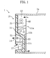
- a protruding portion (12) protruding toward the internal side of the container is formed in a lower portion of the casing body partitioning the container into the internal side and the external side thereof.
- the stays (50) extending in a vertical direction are mounted on both sides of the rear surface of the protruding portion (12) in the casing body (11).
- side frames (40) each located above the protruding portion (12) and extending from the casing body (11) to a top end of the stay (50) are mounted on both sides of an upper portion of a rear surface in the casing body (11).
- the side frames (40) and the stays (50) are coupled to each other.
- the stays (50) are mounted on the lower portion of the rear surface of the casing body (11).
- the stays (50) respectively abut on the side frames (40) mounted on the both sides of the upper portion of the casing body (11).
- the stay (50) and the side frame (40) are coupled to each other. Therefore, this structure allows the casing body (11) to deform under a stress exerted on the casing body (11) toward the interior of the container. This reduces the stress exerted on the casing body (11).
- a bottom tip of the side frame (40) and the top end of the stay (50) are fixed and coupled by a fixing member.
- the top end of the stay (50) abuts on the bottom tip of the side frame (40).
- the top end of the stay (50) and the bottom tip of the side frame (40) are fixed by the fixing member. Therefore, this structure ensures that the casing body (11) is allowed to deform under a stress exerted on the casing body (11) toward the interior of the container. As a result, the stress exerted on the casing body (11) is reduced.
- the top end surface of the stay (50) is formed to be a fixing surface (53) which is horizontally disposed, whereas in the bottom tip of the side frame (40), a fixing surface (43) which is horizontally disposed is formed so as to be in contact with the fixing surface (53) of the stay (50).
- the fixing surface (53) which is horizontally disposed and is formed in the top end surface of the stay (50) is in contact with the fixing surface (43) which is horizontally disposed and is formed at the bottom tip of the side frame (40).
- the stay (50) supports the side frame (40) through the fixing surfaces (43, 53) from the lower side of the side frame (40).
- the fixing member includes one or more bolts for fixing the side frame (40) and the stay (50), while the fixing surface (43) of the side frame (40) and the fixing surface (53) of the stay (50) are in contact with each other.
- the fixing surface (43) of the side frame (40) is fixed to the fixing surface (53) of the stay (50) by one or more bolts, while the fixing surface (43) of the side frame (40) and the fixing surface (53) of the stay (50) are in contact with each other.
- the side frame (40) and the stay (50) are fixed to each other, while the stay (50) supports the side frame (40) from the lower side thereof.
- a single one of the bolts is provided.
- the side frame (40) and stay (50) are fixed by the single one of the bolts, thereby providing flexibility in a direction in which the bolt rotates around an axis thereof. Since the flexibility is imparted, the casing body (11) is allowed to deform, and the stay (50) is prevented from breaking down.
- a sealing member (64) is provided between the fixing surface (43) of the side frame (40), and the fixing surface (53) of the stay (50).
- the sealing member (64) is provided in a contact portion between the fixing surface (43) of the side frame (40), and the fixing surface (53) of the stay (50).
- This structure can seal a space occurring between the fixing surface (43) of the side frame (40), and the fixing surface (53) of the stay (50). As a result, air or water can be prevented from leaking from the interior of the casing.
- the sealing member (64) is an elastic body.
- the sealing member (64) has elastic properties, thereby providing flexibility in a longitudinal direction of the stay (50), for example, in the axial direction of the bolt in the sixth aspect of the invention. Since the flexibility is imparted, this ensures that the casing body (11) is allowed to deform.
- the divided stays (50) are mounted on the both ends of the lower portion of the rear surface of the casing body (11).
- the divided stay (50) supports and fixes the side frame (40) from the lower side thereof.
- the casing body (11) deforms toward the interior of the container under a stress exerted on the casing body (11) toward the interior of the container. This reduces the stress exerted on the casing body (11) toward the interior of the container.
- the casing body (11) has a sufficient strength against the racking load.
- the stay (50) of the present invention is divided, thereby decreasing the length of the stay (50) in the longitudinal direction thereof. As a result, a component cost of the stay (50) can be reduced.
- the bottom tip of the side frame (40) and the top end of the stay (50) are fixed. Therefore, when a racking load is applied, the casing body (11) surely deforms toward the interior of the container under a stress exerted on the casing body (11) toward the interior of the container. This reduces the stress exerted on the casing body (11) toward the interior of the container.
- the fixing surface (53) which is horizontally disposed is formed at the top end surface of the stay (50). Also, the fixing surface (43) which is horizontally disposed is formed at the bottom tip of the side frame (40). Therefore, the stay (50) can be mounted by bringing the fixing surface (53) in the top end surface of the stay (50) into contact with the fixing surface (43) of the bottom tip of the side frame (40). With this structure, the stays (50) can support the side frame (40) from the lower side thereof.
- the contact portion between the fixing surface (43) of the side frame (40), and the fixing surface (53) of the stay (50) is fixed by the bolt. Therefore, the stay (50) and the side frame (40) can be fixed, while the stay (50) supports the side frame (40) from the lower side thereof.
- the side frame (40) and the stay (50) are fixed by the single one of the bolts, thereby providing flexibility in a direction in which the bolt rotates around an axis thereof.
- the casing body (11) is allowed to deform, and the stays (50) is prevented from breaking down.
- the sealing member (64) is provided between the fixing surface (43) of the side frame (40), and the fixing surface (53) of the stay (50). Therefore, this structure can prevent a space from occurring in a contact portion between the fixing surface (43) of the side frame (40), and the fixing surface (53) of the stay (50). As a result, air or water can be prevented from leaking from the interior of the casing (10).
- the sealing member (64) has elastic properties, thereby providing flexibility in the longitudinal direction of the stay (50), for example, in the axial direction of the bolt in the sixth aspect of the invention. Since the flexibility is imparted, thereby ensuring that the casing body (11) is allowed to deform.
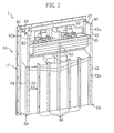
- a container refrigeration unit (1) cools an interior of a container used in marine transport or other transports.
- the container refrigeration unit (1) includes a refrigerant circuit provided with a compressor (17), a condenser (13), and an evaporator (32) to operate a refrigeration cycle.
- a casing (10) of the container refrigeration unit (1) includes a casing body (11) partitioning the container into the internal side and the external side thereof, and a partition plate (48) provided on a rear surface (the internal side) of the casing (10).
- the casing body (11) has a dual structure of an internal casing (11a) made of aluminum, and an external casing (11b) made of FRP.
- a thermal insulating layer (11c) made of a foaming agent is formed between the internal casing (11a) and the external casing (11b).
- a protruding portion (12) protruding toward the internal side of the container is formed.
- the interior of the protruding portion (12) is formed to be an external storage space (S1), whereas an internal storage space (S2) located above the protruding portion (12) is formed in an upper portion of the rear surface of the casing (10).
- the compressor (17), the condenser (13), an external fan (14), and an electrical component box (15) are contained, whereas an evaporator (32), and an internal fan (31) are contained in the internal storage space (S2).
- an inspection window (18) and a ventilator (19) are provided in the upper portion of the casing (11).
- the side stays (50) are provided at both sides of the rear surface of the protruding portion (12) in the casing (11), whereas evaporator frames (40) serving as side frames are provided at both sides of the upper portion of the rear surface (the internal side) of the casing body (11).
- the side stay (50) which characterizes the invention is formed to have a length extending from a bottom end of the casing body (11) to a top end of the protruding portion (12) and a bottom end of the evaporator frame (40).
- the stay (50) is configured to be shorter than conventional stays, and to be separated from the frame (40).
- the side stay (50) is formed by bending mounting pieces (51, 52) respectively located at the front and back sides of a main plate (54) extending vertically.
- the mounting pieces (51, 52) are formed so as to have a U-shape in horizontal cross-section, and a fixing piece (53) is formed at top ends thereof.
- a plurality of bolt holes (51a, 52a) are formed at the mounting pieces (51, 52).
- the one mounting piece (51) is mounted on the rear surface of the protruding portion (12) by the bolt, and the other mounting piece (52) is mounted on a partition plate (48) by the bolt.
- the fixing piece (53) includes a bolt hole (53a), and is horizontally formed to close the top end of the side stay (50).
- the upper surface of the fixing piece (53) is formed to be a fixing surface which is horizontally disposed.
- the evaporator frame (40) which forms the internal storage space (S2) extends from the rear surface of the casing body (11) toward the internal side.
- the evaporator frame (40) is formed by a sheet metal member made of aluminum, where a top flange (45), a bottom flange (44), a front flange (41), a rear flange (42), and a fixing flange (43) located around a frame body (47) are bent inwardly.
- a length of the frame body (47) in a front to back direction is identical with a length from the rear surface of the casing body (11) to a rear surface of the side stay (50), whereas a length of the frame body (47) in a vertical direction is identical with a length from the top end of the casing body (11) to the upper surface of the protruding portion (12).
- a plurality of bolt holes (41a, 42a) are formed in the front flange (41) and the rear flange (42).
- the front flange (41) is mounted on the rear surface of the casing body (11) by the bolt
- the partition plate (48) is mounted on the rear flange (42) by the bolt.
- the bottom end of the frame body (47) and the bottom flange (44) are formed along the upper surface of the protruding portion (12), and are inclined downwardly toward the rearward that is the internal side.
- the fixing flange (43) is formed at the rear end of the frame body (47) which is the bottom end of the frame body (47) and located in the internal side.
- the fixing flange (43) includes a bolt hole (43a), and the lower surface of the fixing flange (43) is formed to be a fixing surface which is horizontally deposited, according to the fixing piece (53) of the side stay (50).
- the fixing flange (43) is integrally formed with the fixing piece (53) of the side stay (50) by the bolt.
- the bottom tip of the evaporator frame (40) and the top end of the side stay (50) are fixed by the one bolt which serves as a fixing member, so that the evaporator frame (40) and the side stay (50) are coupled to each other.
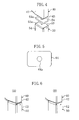
- a sealing member (64) is provided between the fixing flange (43) of the evaporator frame (40), and the fixing piece (53) of the side stay (50). As shown in FIG. 5 , the sealing member (64) has substantially the same shape as the fixture surface formed in the fixing flange (43). The sealing member (64) is formed by an elastic body, thereby preventing air or water from leaking from the interior of the internal casing (11a).
- FIG. 6A when the side stay (50) is divided, a space is formed in the mounting piece (52) at the internal side.
- the air or water in the internal storage space (S2) leaks from this space.
- FIG. 6B the top end of the mounting piece (52) located in the internal side is extended upwardly to seal the space. This structure prevents the air or water from leaking from the interior of the internal casing (11a).
- the evaporator frames (40) located at right and left sides are coupled by a coupling member (46), whereas a plurality of sub stays (56) each extending vertically are mounted on the rear surface of protruding portion (12) of the casing body (11).
- the top end of the middle sub stay (56) located at the middle portion is coupled to the coupling member (46) through an auxiliary member (55).
- the partition plate (48) is formed to be a piece of plate, and is mounted on the side stays (50), the evaporator frames (40), and the sub stays (56) so as to cover the rearward of the casing body (11).
- the internal storage space (S2) is arranged with the evaporator frame (40) and the partition plate (48), whereas a space between protruding portion (12) and the partition plate (48) is configured to be an air passageway (S3).
- the top end of the air passageway (S3) is communicated with the internal storage space (S2), whereas the bottom end of the air passageway (S3) is communicated with the interior of the container.
- the operation of the container refrigeration unit (1) is started by driving the compressor (17), the external fan (14), and the internal fan (31).
- a suction refrigerant of the compressor (17) is sent to the condenser (13).
- heat of the refrigerant is taken as heat of an external air sent by the external fan (14).
- the refrigerant dissipates the heat into the external air, and is condensed.
- the refrigerant condensed in the condenser (13) is sent to the evaporator (32) after being depressed by an expansion valve.
- heat of the refrigerant is taken as heat of an external air sent by the internal fan (31).
- the refrigerant evaporates by absorbing the heat from the internal air, thereby cooling the internal air.
- a conventional unit has the side stays mounted from the lower portion of the rear surface of the evaporator frame to the lower portion of the rear surface of the casing body, and it has a strength against the stress. Therefore, the casing body does not break down.
- the side stays (50) are formed separately from the frames (40) and attached to them, and the casing body (11) deforms toward the interior of the container under a stress exerted on the casing body (11) toward the interior of the container. This reduces the stress exerted on the casing body (11) toward the interior of the container.
- the divided side stays (50) are mounted on the both ends of the lower rear surface of the casing body (11).
- the divided side stay (50) supports the evaporator frame (40) from the lower side thereof, and is fixed by the bolt. Therefore, when a racking load is applied, the casing body (11) deforms toward the interior of the container under a stress exerted on the casing body (11) toward the interior of the container. This reduces the stress exerted on the casing body (11) toward the interior of the container. As a result, the casing body (11) has a sufficient strength against the racking load.
- the side stay (50) of the present invention is divided, thereby decreasing the length of the side stay (50) in the longitudinal direction thereof. As a result, a component cost of the side stay (50) can be reduced.
- the bottom tip of the evaporator frame (40) and the top end of the side stay (50) are fixed. Therefore, when a racking load is applied, the casing body (11) surely deforms toward the interior of the container under a stress exerted on the casing body (11) toward the interior of the container. This reduces the stress toward the interior of the casing body (11) toward the interior of the container.
- the fixing surface (53) which is horizontally disposed is formed at the top end of the stay (50).
- the fixing surface (43) which is horizontally disposed is formed at the bottom tip of the side frame (40). Therefore, the stay (50) can be mounted by bringing the fixing surface (53) in the top end surface of the stay (50) into contact with the fixing surface (43) of the bottom tip of the side frame (40). With this structure, the stay (50) can support the side frame (40) from the lower side thereof.
- the contact portion connecting the fixing surface (43) of the evaporator frame (40) and the fixing surface (53) of the side stay (50) are fixed by the bolt. Therefore, the side stay (50) and the evaporator frame (40) can be fixed while the side stay (50) supports the evaporator frames (40) from the lower side thereof.
- the evaporator frame (40) and the side stay (50) are fixed by the single one of the bolts, thereby providing flexibility in a direction in which the bolt rotates around an axis thereof.
- the casing body (11) is allowed to deform, and the side stay (50) is prevented from breaking down.
- the sealing member (64) is provided between the fixing surface (43) of the side frame (40), and the fixing surface (53) of the side stay (50). Therefore, this structure can prevent a space from occurring in the contact portion between the fixing surface (43) of the side frame (40), and the fixing surface (53) of the side stay (50). As a result, air or water can be prevented from leaking from the interior casing (10a).
- the sealing member (64) has elastic properties, thereby providing flexibility in the longitudinal direction of the side stay (50), for example, in the axial direction of the bolt. Since the flexibility is imparted, thereby ensuring that the casing body (11) is allowed to deform.
- the present invention applies to the support structure of the casing (10) of the container refrigeration unit (1).
- the present invention is also applicable to a support structure in other units and the like.
- the present invention is useful for a support structure of a casing in a container refrigeration unit.
Applications Claiming Priority (2)
| Application Number | Priority Date | Filing Date | Title |
|---|---|---|---|
| JP2007205705 | 2007-08-07 | ||
| PCT/JP2008/002160 WO2009019884A1 (ja) | 2007-08-07 | 2008-08-07 | コンテナ用冷凍機 |
Publications (3)
| Publication Number | Publication Date |
|---|---|
| EP2187155A1 true EP2187155A1 (de) | 2010-05-19 |
| EP2187155A4 EP2187155A4 (de) | 2016-02-24 |
| EP2187155B1 EP2187155B1 (de) | 2018-08-01 |
Family
ID=40341125
Family Applications (1)
| Application Number | Title | Priority Date | Filing Date |
|---|---|---|---|
| EP08790417.3A Not-in-force EP2187155B1 (de) | 2007-08-07 | 2008-08-07 | Kühlvorrichtung für behältnis |
Country Status (6)
| Country | Link |
|---|---|
| US (1) | US8366222B2 (de) |
| EP (1) | EP2187155B1 (de) |
| JP (1) | JP4254908B2 (de) |
| CN (1) | CN101688741B (de) |
| TW (1) | TW200923298A (de) |
| WO (1) | WO2009019884A1 (de) |
Families Citing this family (4)
| Publication number | Priority date | Publication date | Assignee | Title |
|---|---|---|---|---|
| JP4254908B2 (ja) * | 2007-08-07 | 2009-04-15 | ダイキン工業株式会社 | コンテナ用冷凍機 |
| WO2011060503A1 (en) * | 2009-11-20 | 2011-05-26 | Electrolux Home Products Pty Limited | Improved engine mounting and assembly of modular refrigeration engine to a cabinet of a refrigeration appliance |
| JP5751179B2 (ja) * | 2012-01-20 | 2015-07-22 | 株式会社デンソー | コンテナ用冷凍装置 |
| JP6863427B2 (ja) * | 2019-09-30 | 2021-04-21 | ダイキン工業株式会社 | コンテナ用冷凍装置 |
Family Cites Families (27)
| Publication number | Priority date | Publication date | Assignee | Title |
|---|---|---|---|---|
| US2579396A (en) * | 1946-04-03 | 1951-12-18 | Nash Kelvinator Corp | Method of making refrigerator cabinets |
| US3707243A (en) * | 1970-01-20 | 1972-12-26 | Philips Corp | Refrigerator cabinets |
| US4116507A (en) * | 1977-11-07 | 1978-09-26 | The Raymond Lee Organization, Inc. | Radiator concealing article of furniture |
| US4370795A (en) * | 1980-11-24 | 1983-02-01 | The Budd Company | Apparatus and methods to provide shoring during the manufacturing of a reefer container |
| DE3129005C2 (de) * | 1981-06-29 | 1986-02-06 | Graaff Kg, 3210 Elze | Dachplatte hoher Festigkeit für einen Kühlbehälter |
| JPS5820190U (ja) * | 1981-07-29 | 1983-02-07 | 日本電気ホームエレクトロニクス株式会社 | 電気冷蔵庫 |
| AU573457B2 (en) * | 1986-10-21 | 1988-06-09 | Nippon Light Metal Company Ltd. | Refrigerated transport |
| US4920696A (en) * | 1989-02-03 | 1990-05-01 | While Consolidated Industries, Inc. | Refrigeration compressor mount |
| JPH0694355A (ja) * | 1992-09-10 | 1994-04-05 | Mitsubishi Heavy Ind Ltd | コンテナ用冷凍ユニットのフレーム |
| US5501076A (en) * | 1993-04-14 | 1996-03-26 | Marlow Industries, Inc. | Compact thermoelectric refrigerator and module |
| US5669232A (en) * | 1994-11-22 | 1997-09-23 | Sanyo Electric Co., Ltd. | Refrigerating unit |
| JP3612792B2 (ja) * | 1995-06-13 | 2005-01-19 | ダイキン工業株式会社 | 冷凍コンテナ用冷凍装置のケーシング構造 |
| JPH0924990A (ja) | 1995-07-07 | 1997-01-28 | Daikin Ind Ltd | コンテナ用冷凍装置 |
| JP3309737B2 (ja) * | 1996-11-01 | 2002-07-29 | ダイキン工業株式会社 | コンテナ用冷凍装置 |
| JP2880464B2 (ja) * | 1996-11-15 | 1999-04-12 | 中野冷機株式会社 | アラウンドショーケース |
| JPH1114243A (ja) * | 1997-06-23 | 1999-01-22 | Daikin Ind Ltd | コンテナ用冷凍装置 |
| FR2832787B1 (fr) * | 2001-11-23 | 2004-04-02 | Landry Nivor | Bac isotherme refrigerant pouvant fonctionner sur le secteur ou avec des piles ou des panneaux solaires |
| US6773082B2 (en) * | 2002-01-28 | 2004-08-10 | Daewoo Electronics Corp. | Refrigerator using EPS insulating material |
| US7185509B2 (en) * | 2002-08-31 | 2007-03-06 | Samsung Electronics Co., Ltd. | Refrigerator |
| US20080006041A1 (en) * | 2004-03-01 | 2008-01-10 | Yasutaka Nakata | Refrigerator, Freezer, Storage Container and Cold Storage |
| KR100548306B1 (ko) * | 2004-05-18 | 2006-02-02 | 엘지전자 주식회사 | 진동 절연형 냉장고 |
| CN100541076C (zh) * | 2005-05-10 | 2009-09-16 | 乐金电子(天津)电器有限公司 | 冰箱的高度调整装置 |
| JP4020140B2 (ja) * | 2005-12-16 | 2007-12-12 | ダイキン工業株式会社 | コンテナ用冷凍装置の電装品ボックス |
| JP4934446B2 (ja) * | 2007-01-31 | 2012-05-16 | 三洋電機株式会社 | 冷却貯蔵庫 |
| JP4281823B2 (ja) * | 2007-07-13 | 2009-06-17 | ダイキン工業株式会社 | コンテナ用冷凍装置及びその製造方法 |
| JP4333783B2 (ja) * | 2007-07-24 | 2009-09-16 | ダイキン工業株式会社 | コンテナ用冷凍装置及びその製造方法 |
| JP4254908B2 (ja) * | 2007-08-07 | 2009-04-15 | ダイキン工業株式会社 | コンテナ用冷凍機 |
-
2008
- 2008-08-07 JP JP2008203823A patent/JP4254908B2/ja active Active
- 2008-08-07 US US12/672,204 patent/US8366222B2/en not_active Expired - Fee Related
- 2008-08-07 TW TW097130133A patent/TW200923298A/zh not_active IP Right Cessation
- 2008-08-07 CN CN2008800232938A patent/CN101688741B/zh active Active
- 2008-08-07 EP EP08790417.3A patent/EP2187155B1/de not_active Not-in-force
- 2008-08-07 WO PCT/JP2008/002160 patent/WO2009019884A1/ja active Application Filing
Non-Patent Citations (1)
| Title |
|---|
| See references of WO2009019884A1 * |
Also Published As
| Publication number | Publication date |
|---|---|
| WO2009019884A1 (ja) | 2009-02-12 |
| CN101688741B (zh) | 2012-01-18 |
| TWI359253B (de) | 2012-03-01 |
| TW200923298A (en) | 2009-06-01 |
| CN101688741A (zh) | 2010-03-31 |
| US20110148266A1 (en) | 2011-06-23 |
| EP2187155B1 (de) | 2018-08-01 |
| US8366222B2 (en) | 2013-02-05 |
| EP2187155A4 (de) | 2016-02-24 |
| JP4254908B2 (ja) | 2009-04-15 |
| JP2009057111A (ja) | 2009-03-19 |
Similar Documents
| Publication | Publication Date | Title |
|---|---|---|
| EP2187155B1 (de) | Kühlvorrichtung für behältnis | |
| WO2010137258A1 (ja) | トレーラ用冷凍装置 | |
| WO2006108649A8 (de) | Kühl- und/oder gefriergerät | |
| JP6038446B2 (ja) | 断熱キャビネット | |
| US10408523B2 (en) | Component mounting in an integrated refrigerated container | |
| JP6695020B2 (ja) | 冷蔵庫 | |
| JP4281823B2 (ja) | コンテナ用冷凍装置及びその製造方法 | |
| EP3044126B1 (de) | Montageverfahren eines gekühlten cargo containers | |
| JP2006220386A (ja) | 冷蔵庫 | |
| EP2442055B1 (de) | Kühlvorrichtung für einen anhänger | |
| KR101385256B1 (ko) | 화물차량의 컴프레서 체결용 브라켓트 | |
| JP2003207254A (ja) | 電気冷蔵庫 | |
| JP5514037B2 (ja) | 冷蔵庫 | |
| JP2009008304A (ja) | コンテナ用冷凍装置 | |
| JP5588728B2 (ja) | 車載用冷凍装置のフレーム構造 | |
| JP2009041811A (ja) | コンテナ用冷凍装置 | |
| TWI542500B (zh) | Frame construction of refrigeration device for vehicle | |
| WO2021065119A1 (ja) | コンテナ用冷凍装置 | |
| JP5040477B2 (ja) | コンテナ用冷凍機 | |
| JP2022020229A (ja) | 冷却ユニットおよび保冷庫ならびに移動可能な保冷庫 | |
| JP2007322000A (ja) | コンテナ用冷凍装置 | |
| KR100782882B1 (ko) | 배관 연결구조 | |
| JP2019143888A (ja) | 冷却貯蔵庫 | |
| JP2009024908A (ja) | コンテナ用冷凍装置及びその製造方法 |
Legal Events
| Date | Code | Title | Description |
|---|---|---|---|
| PUAI | Public reference made under article 153(3) epc to a published international application that has entered the european phase |
Free format text: ORIGINAL CODE: 0009012 |
|
| 17P | Request for examination filed |
Effective date: 20100224 |
|
| AK | Designated contracting states |
Kind code of ref document: A1 Designated state(s): AT BE BG CH CY CZ DE DK EE ES FI FR GB GR HR HU IE IS IT LI LT LU LV MC MT NL NO PL PT RO SE SI SK TR |
|
| AX | Request for extension of the european patent |
Extension state: AL BA MK RS |
|
| DAX | Request for extension of the european patent (deleted) | ||
| RA4 | Supplementary search report drawn up and despatched (corrected) |
Effective date: 20160125 |
|
| RIC1 | Information provided on ipc code assigned before grant |
Ipc: F25D 23/06 20060101AFI20160119BHEP Ipc: B65D 88/12 20060101ALI20160119BHEP |
|
| GRAP | Despatch of communication of intention to grant a patent |
Free format text: ORIGINAL CODE: EPIDOSNIGR1 |
|
| INTG | Intention to grant announced |
Effective date: 20180327 |
|
| GRAS | Grant fee paid |
Free format text: ORIGINAL CODE: EPIDOSNIGR3 |
|
| GRAA | (expected) grant |
Free format text: ORIGINAL CODE: 0009210 |
|
| AK | Designated contracting states |
Kind code of ref document: B1 Designated state(s): AT BE BG CH CY CZ DE DK EE ES FI FR GB GR HR HU IE IS IT LI LT LU LV MC MT NL NO PL PT RO SE SI SK TR |
|
| REG | Reference to a national code |
Ref country code: GB Ref legal event code: FG4D |
|
| REG | Reference to a national code |
Ref country code: CH Ref legal event code: EP Ref country code: AT Ref legal event code: REF Ref document number: 1024786 Country of ref document: AT Kind code of ref document: T Effective date: 20180815 |
|
| REG | Reference to a national code |
Ref country code: IE Ref legal event code: FG4D |
|
| REG | Reference to a national code |
Ref country code: DE Ref legal event code: R096 Ref document number: 602008056269 Country of ref document: DE |
|
| REG | Reference to a national code |
Ref country code: NL Ref legal event code: FP |
|
| PGFP | Annual fee paid to national office [announced via postgrant information from national office to epo] |
Ref country code: NL Payment date: 20180813 Year of fee payment: 11 Ref country code: DE Payment date: 20180828 Year of fee payment: 11 |
|
| REG | Reference to a national code |
Ref country code: LT Ref legal event code: MG4D |
|
| REG | Reference to a national code |
Ref country code: AT Ref legal event code: MK05 Ref document number: 1024786 Country of ref document: AT Kind code of ref document: T Effective date: 20180801 |
|
| PG25 | Lapsed in a contracting state [announced via postgrant information from national office to epo] |
Ref country code: IS Free format text: LAPSE BECAUSE OF FAILURE TO SUBMIT A TRANSLATION OF THE DESCRIPTION OR TO PAY THE FEE WITHIN THE PRESCRIBED TIME-LIMIT Effective date: 20181201 Ref country code: FI Free format text: LAPSE BECAUSE OF FAILURE TO SUBMIT A TRANSLATION OF THE DESCRIPTION OR TO PAY THE FEE WITHIN THE PRESCRIBED TIME-LIMIT Effective date: 20180801 Ref country code: GR Free format text: LAPSE BECAUSE OF FAILURE TO SUBMIT A TRANSLATION OF THE DESCRIPTION OR TO PAY THE FEE WITHIN THE PRESCRIBED TIME-LIMIT Effective date: 20181102 Ref country code: BG Free format text: LAPSE BECAUSE OF FAILURE TO SUBMIT A TRANSLATION OF THE DESCRIPTION OR TO PAY THE FEE WITHIN THE PRESCRIBED TIME-LIMIT Effective date: 20181101 Ref country code: NO Free format text: LAPSE BECAUSE OF FAILURE TO SUBMIT A TRANSLATION OF THE DESCRIPTION OR TO PAY THE FEE WITHIN THE PRESCRIBED TIME-LIMIT Effective date: 20181101 Ref country code: AT Free format text: LAPSE BECAUSE OF FAILURE TO SUBMIT A TRANSLATION OF THE DESCRIPTION OR TO PAY THE FEE WITHIN THE PRESCRIBED TIME-LIMIT Effective date: 20180801 Ref country code: SE Free format text: LAPSE BECAUSE OF FAILURE TO SUBMIT A TRANSLATION OF THE DESCRIPTION OR TO PAY THE FEE WITHIN THE PRESCRIBED TIME-LIMIT Effective date: 20180801 Ref country code: PL Free format text: LAPSE BECAUSE OF FAILURE TO SUBMIT A TRANSLATION OF THE DESCRIPTION OR TO PAY THE FEE WITHIN THE PRESCRIBED TIME-LIMIT Effective date: 20180801 Ref country code: LT Free format text: LAPSE BECAUSE OF FAILURE TO SUBMIT A TRANSLATION OF THE DESCRIPTION OR TO PAY THE FEE WITHIN THE PRESCRIBED TIME-LIMIT Effective date: 20180801 |
|
| PG25 | Lapsed in a contracting state [announced via postgrant information from national office to epo] |
Ref country code: HR Free format text: LAPSE BECAUSE OF FAILURE TO SUBMIT A TRANSLATION OF THE DESCRIPTION OR TO PAY THE FEE WITHIN THE PRESCRIBED TIME-LIMIT Effective date: 20180801 Ref country code: LV Free format text: LAPSE BECAUSE OF FAILURE TO SUBMIT A TRANSLATION OF THE DESCRIPTION OR TO PAY THE FEE WITHIN THE PRESCRIBED TIME-LIMIT Effective date: 20180801 Ref country code: ES Free format text: LAPSE BECAUSE OF FAILURE TO SUBMIT A TRANSLATION OF THE DESCRIPTION OR TO PAY THE FEE WITHIN THE PRESCRIBED TIME-LIMIT Effective date: 20180801 |
|
| REG | Reference to a national code |
Ref country code: CH Ref legal event code: PL |
|
| PG25 | Lapsed in a contracting state [announced via postgrant information from national office to epo] |
Ref country code: MC Free format text: LAPSE BECAUSE OF FAILURE TO SUBMIT A TRANSLATION OF THE DESCRIPTION OR TO PAY THE FEE WITHIN THE PRESCRIBED TIME-LIMIT Effective date: 20180801 Ref country code: LI Free format text: LAPSE BECAUSE OF NON-PAYMENT OF DUE FEES Effective date: 20180831 Ref country code: RO Free format text: LAPSE BECAUSE OF FAILURE TO SUBMIT A TRANSLATION OF THE DESCRIPTION OR TO PAY THE FEE WITHIN THE PRESCRIBED TIME-LIMIT Effective date: 20180801 Ref country code: CZ Free format text: LAPSE BECAUSE OF FAILURE TO SUBMIT A TRANSLATION OF THE DESCRIPTION OR TO PAY THE FEE WITHIN THE PRESCRIBED TIME-LIMIT Effective date: 20180801 Ref country code: CH Free format text: LAPSE BECAUSE OF NON-PAYMENT OF DUE FEES Effective date: 20180831 Ref country code: EE Free format text: LAPSE BECAUSE OF FAILURE TO SUBMIT A TRANSLATION OF THE DESCRIPTION OR TO PAY THE FEE WITHIN THE PRESCRIBED TIME-LIMIT Effective date: 20180801 Ref country code: IT Free format text: LAPSE BECAUSE OF FAILURE TO SUBMIT A TRANSLATION OF THE DESCRIPTION OR TO PAY THE FEE WITHIN THE PRESCRIBED TIME-LIMIT Effective date: 20180801 Ref country code: LU Free format text: LAPSE BECAUSE OF NON-PAYMENT OF DUE FEES Effective date: 20180807 |
|
| REG | Reference to a national code |
Ref country code: DE Ref legal event code: R097 Ref document number: 602008056269 Country of ref document: DE |
|
| REG | Reference to a national code |
Ref country code: BE Ref legal event code: MM Effective date: 20180831 |
|
| REG | Reference to a national code |
Ref country code: IE Ref legal event code: MM4A |
|
| PG25 | Lapsed in a contracting state [announced via postgrant information from national office to epo] |
Ref country code: DK Free format text: LAPSE BECAUSE OF FAILURE TO SUBMIT A TRANSLATION OF THE DESCRIPTION OR TO PAY THE FEE WITHIN THE PRESCRIBED TIME-LIMIT Effective date: 20180801 Ref country code: SK Free format text: LAPSE BECAUSE OF FAILURE TO SUBMIT A TRANSLATION OF THE DESCRIPTION OR TO PAY THE FEE WITHIN THE PRESCRIBED TIME-LIMIT Effective date: 20180801 |
|
| PLBE | No opposition filed within time limit |
Free format text: ORIGINAL CODE: 0009261 |
|
| STAA | Information on the status of an ep patent application or granted ep patent |
Free format text: STATUS: NO OPPOSITION FILED WITHIN TIME LIMIT |
|
| 26N | No opposition filed |
Effective date: 20190503 |
|
| GBPC | Gb: european patent ceased through non-payment of renewal fee |
Effective date: 20181101 |
|
| PG25 | Lapsed in a contracting state [announced via postgrant information from national office to epo] |
Ref country code: IE Free format text: LAPSE BECAUSE OF NON-PAYMENT OF DUE FEES Effective date: 20180807 |
|
| PG25 | Lapsed in a contracting state [announced via postgrant information from national office to epo] |
Ref country code: BE Free format text: LAPSE BECAUSE OF NON-PAYMENT OF DUE FEES Effective date: 20180831 Ref country code: FR Free format text: LAPSE BECAUSE OF NON-PAYMENT OF DUE FEES Effective date: 20181001 Ref country code: SI Free format text: LAPSE BECAUSE OF FAILURE TO SUBMIT A TRANSLATION OF THE DESCRIPTION OR TO PAY THE FEE WITHIN THE PRESCRIBED TIME-LIMIT Effective date: 20180801 |
|
| PG25 | Lapsed in a contracting state [announced via postgrant information from national office to epo] |
Ref country code: GB Free format text: LAPSE BECAUSE OF NON-PAYMENT OF DUE FEES Effective date: 20181101 |
|
| PG25 | Lapsed in a contracting state [announced via postgrant information from national office to epo] |
Ref country code: MT Free format text: LAPSE BECAUSE OF NON-PAYMENT OF DUE FEES Effective date: 20180807 |
|
| REG | Reference to a national code |
Ref country code: DE Ref legal event code: R119 Ref document number: 602008056269 Country of ref document: DE |
|
| PG25 | Lapsed in a contracting state [announced via postgrant information from national office to epo] |
Ref country code: TR Free format text: LAPSE BECAUSE OF FAILURE TO SUBMIT A TRANSLATION OF THE DESCRIPTION OR TO PAY THE FEE WITHIN THE PRESCRIBED TIME-LIMIT Effective date: 20180801 |
|
| REG | Reference to a national code |
Ref country code: NL Ref legal event code: MM Effective date: 20190901 |
|
| PG25 | Lapsed in a contracting state [announced via postgrant information from national office to epo] |
Ref country code: PT Free format text: LAPSE BECAUSE OF FAILURE TO SUBMIT A TRANSLATION OF THE DESCRIPTION OR TO PAY THE FEE WITHIN THE PRESCRIBED TIME-LIMIT Effective date: 20180801 Ref country code: HU Free format text: LAPSE BECAUSE OF FAILURE TO SUBMIT A TRANSLATION OF THE DESCRIPTION OR TO PAY THE FEE WITHIN THE PRESCRIBED TIME-LIMIT; INVALID AB INITIO Effective date: 20080807 |
|
| PG25 | Lapsed in a contracting state [announced via postgrant information from national office to epo] |
Ref country code: CY Free format text: LAPSE BECAUSE OF FAILURE TO SUBMIT A TRANSLATION OF THE DESCRIPTION OR TO PAY THE FEE WITHIN THE PRESCRIBED TIME-LIMIT Effective date: 20180801 |
|
| PG25 | Lapsed in a contracting state [announced via postgrant information from national office to epo] |
Ref country code: DE Free format text: LAPSE BECAUSE OF NON-PAYMENT OF DUE FEES Effective date: 20200303 Ref country code: NL Free format text: LAPSE BECAUSE OF NON-PAYMENT OF DUE FEES Effective date: 20190901 |
|
| P01 | Opt-out of the competence of the unified patent court (upc) registered |
Effective date: 20230525 |