EP2186759A1 - Vorrichtung zum Versetzen von Behältern - Google Patents
Vorrichtung zum Versetzen von Behältern Download PDFInfo
- Publication number
- EP2186759A1 EP2186759A1 EP09175852A EP09175852A EP2186759A1 EP 2186759 A1 EP2186759 A1 EP 2186759A1 EP 09175852 A EP09175852 A EP 09175852A EP 09175852 A EP09175852 A EP 09175852A EP 2186759 A1 EP2186759 A1 EP 2186759A1
- Authority
- EP
- European Patent Office
- Prior art keywords
- arms
- turntable
- grippers
- container
- actuating element
- Prior art date
- Legal status (The legal status is an assumption and is not a legal conclusion. Google has not performed a legal analysis and makes no representation as to the accuracy of the status listed.)
- Granted
Links
- 230000000994 depressogenic effect Effects 0.000 claims description 6
- 238000003825 pressing Methods 0.000 claims description 4
- 230000001105 regulatory effect Effects 0.000 claims description 3
- 210000003739 neck Anatomy 0.000 description 16
- 238000006073 displacement reaction Methods 0.000 description 9
- 238000004519 manufacturing process Methods 0.000 description 6
- 230000007246 mechanism Effects 0.000 description 3
- 230000000717 retained effect Effects 0.000 description 3
- 230000006978 adaptation Effects 0.000 description 2
- 238000002372 labelling Methods 0.000 description 2
- 229910000831 Steel Inorganic materials 0.000 description 1
- 235000013361 beverage Nutrition 0.000 description 1
- 230000005540 biological transmission Effects 0.000 description 1
- 230000000694 effects Effects 0.000 description 1
- 239000011521 glass Substances 0.000 description 1
- 239000012729 immediate-release (IR) formulation Substances 0.000 description 1
- 229910052500 inorganic mineral Inorganic materials 0.000 description 1
- 230000002452 interceptive effect Effects 0.000 description 1
- 238000012423 maintenance Methods 0.000 description 1
- 230000007257 malfunction Effects 0.000 description 1
- 239000000463 material Substances 0.000 description 1
- 238000000034 method Methods 0.000 description 1
- 239000011707 mineral Substances 0.000 description 1
- 239000010959 steel Substances 0.000 description 1
- 230000001360 synchronised effect Effects 0.000 description 1
- XLYOFNOQVPJJNP-UHFFFAOYSA-N water Substances O XLYOFNOQVPJJNP-UHFFFAOYSA-N 0.000 description 1
Images


Classifications
-
- B—PERFORMING OPERATIONS; TRANSPORTING
- B65—CONVEYING; PACKING; STORING; HANDLING THIN OR FILAMENTARY MATERIAL
- B65G—TRANSPORT OR STORAGE DEVICES, e.g. CONVEYORS FOR LOADING OR TIPPING, SHOP CONVEYOR SYSTEMS OR PNEUMATIC TUBE CONVEYORS
- B65G47/00—Article or material-handling devices associated with conveyors; Methods employing such devices
- B65G47/74—Feeding, transfer, or discharging devices of particular kinds or types
- B65G47/84—Star-shaped wheels or devices having endless travelling belts or chains, the wheels or devices being equipped with article-engaging elements
- B65G47/846—Star-shaped wheels or wheels equipped with article-engaging elements
- B65G47/847—Star-shaped wheels or wheels equipped with article-engaging elements the article-engaging elements being grippers
-
- B—PERFORMING OPERATIONS; TRANSPORTING
- B65—CONVEYING; PACKING; STORING; HANDLING THIN OR FILAMENTARY MATERIAL
- B65G—TRANSPORT OR STORAGE DEVICES, e.g. CONVEYORS FOR LOADING OR TIPPING, SHOP CONVEYOR SYSTEMS OR PNEUMATIC TUBE CONVEYORS
- B65G29/00—Rotary conveyors, e.g. rotating discs, arms, star-wheels or cones
-
- B—PERFORMING OPERATIONS; TRANSPORTING
- B65—CONVEYING; PACKING; STORING; HANDLING THIN OR FILAMENTARY MATERIAL
- B65G—TRANSPORT OR STORAGE DEVICES, e.g. CONVEYORS FOR LOADING OR TIPPING, SHOP CONVEYOR SYSTEMS OR PNEUMATIC TUBE CONVEYORS
- B65G2201/00—Indexing codes relating to handling devices, e.g. conveyors, characterised by the type of product or load being conveyed or handled
- B65G2201/02—Articles
- B65G2201/0235—Containers
- B65G2201/0244—Bottles
Definitions
- the present invention concerns an apparatus for transferring containers, in particular bottles or the like, according to the preamble of the main claim.
- the apparatus in question is intended to be used advantageously in industrial plants for bottling beverages, such as wine or mineral water, for conveying the containers, made of glass or plastic, between different operating machines, such as rinsing machines, filling or corking/capping machines, or for conveying the containers inside the same machines.
- beverages such as wine or mineral water
- different operating machines such as rinsing machines, filling or corking/capping machines, or for conveying the containers inside the same machines.
- the abovementioned operating machines have mounted peripherally, on a turntable, a plurality of operating heads with which the containers are associated, along their travel path around the turntable, in order to undergo the operations to be performed by the operating machine.
- Transfer of the containers between the various operating machines, namely around the turntables of the said operating machines, is performed using conveying means such as screw feeders, motor-driven recessed starwheels, retaining grippers and conveyor belts.
- the conveying means are currently adapted so as to retain correctly the containers, by replacing the screw feeders or the grippers, in particular so as to centre the containers correctly with respect to the heads of the operating machines.
- the containers vary their position on the support base of the turntable when there is a variation in size, it is obvious that they will no longer be aligned with the operating heads of the various machines.
- the patent EP 0366225 describes an apparatus for conveying containers, equipped with a turntable rotating about a central axis of rotation.
- a plurality of grippers are mounted peripherally on said turntable, each of these grippers comprising a pair of arms which are pivotably mounted on a turntable support disc.
- the free end of each arm is provided with a projection for facilitating gripping of the containers, while the end connected to the central disc has, keyed thereon, a toothed wheel engaged with the toothed wheel of the other gripper arm.
- a vertical rod is connected at one end to one of the arms of the grippers and at the other end to a cam mechanism.
- the latter comprises a frustoconical cam which acts on a cam follower mechanically coupled with the vertical rod by means of lever mechanisms and resilient means.
- the cam causes a radial displacement of the follower away from or towards the central axis, causing a rotation of the vertical rod which, in turn, causes opening or closing of the gripper arms.
- This conveying apparatus also comprises a control device for adjusting the closing and opening angle of the grippers so as to allow the latter to retain containers which have a base of varying diameter.
- This control device comprises a gear-type raising mechanism which allows lowering or raising of the frustoconical cam so as to keep the cam follower more or less close to the central axis during the entire rotation of the turntable so as to reduce or increase the maximum closing or opening angle of the grippers.
- a first drawback consists in the fact that the grippers of this apparatus are intended to convey only containers with a circular base, but are unable to retain and centre correctly containers with other shapes commonly found in the market, such as bottles with a square, rectangular or triangular base.
- a further drawback consists in the fact that adjustment operations are nevertheless required in order to adapt the grippers so that they can retain containers with different diameters. These operations require stoppage of the entire bottling plant with consequent production downtime and reduced efficiency of the production process.
- the main object of the present invention is therefore to overcome the drawbacks arising with the solutions of the known type considered above by providing an apparatus for transferring containers which allows versatile use when there is variation both in the shape and in the size of the containers, without the need for laborious adaptation procedures.
- a further object of the present invention is to provide an apparatus for transferring containers which allows the containers to be kept centred in their respective seats on the turntables when there is a variation in their shape and size.
- a further object of the present invention is to provide an apparatus for transferring containers which is economical and simple to manufacture.
- a further object of the present invention is to provide an apparatus for transferring containers which is operationally entirely reliable.
- the apparatus 1 may therefore replace a conventional recessed wheel for conveying containers or may be mounted on the supporting structure of a rotary operating machine such as a capsuling machine, a filling machine, a rinsing machine, a corking/capping machine, a labelling machine, and other similar machines.
- a rotary operating machine such as a capsuling machine, a filling machine, a rinsing machine, a corking/capping machine, a labelling machine, and other similar machines.
- the apparatus 1 is installed along a conventional bottling line with the function of picking up the containers 2 advancing on a conveyor belt 3 and then transferring them to a downstream operating machine or to another machine for conveying containers (not shown).
- conveying means such as screw feeders or recessed starwheels may be envisaged in place of the conveyor belt 3.
- the conveying means may consist of a plurality of prongs moved by a motor-driven chain system, as described on Page 7, line 6, or Page 8, line 1, in Patent Application No. PD2006A000226 which is considered appended hereto for reference purposes.
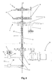
- the apparatus 1 comprises a support structure with a fixed cylindrical body 4 inside which a first drive shaft 5 is coaxially mounted by means of suitable first bearings. Said shaft extends along a vertical axis Z about which it is rotated by motor means M which are schematically indicated in Figure 4 .
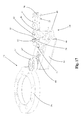
- a first turntable 6 is fixed centrally onto the first shaft 5 and has peripherally mounted thereon at equally spaced intervals a plurality of first grippers 7, the number of which depends on the ratio between the pitch diameter of the main turntable of the operating machine associated with the apparatus 1 and the pitch diameter of the first turntable 6 or, essentially, the number of heads mounted on the main turntable of the operating machine.
- the first turntable 6 is, for example, advantageously formed by a pair of opposite and parallel plates 8 which are fixed to the first drive shaft 5 by means of mechanical unions such as keys and/or hubs with the purpose of allowing the first turntable 6 to rotate, integrally with the first shaft 5, about the vertical axis Z.
- Each first gripper (7) is provided with at least two first arms (9) which are constrained to the plates 8 by means of corresponding first pins 10 with respective first axes Y, Y' parallel to each other and to the vertical axis Z.
- These first arms 9 can be actuated by first actuator means 12 so as to rotate about the parallel axes Y, Y' between a first open position, where their respective first retaining portions 13 are spaced from each other so as to receive or release the containers 2, and a first closed position, where the first retaining portions 13 are close together so as to hold the containers 2 between them.
- each first arm 9 of each first gripper 7 is provided with a slot 15 aligned with the slot of at least one other first arm 9 of the same first gripper 7. Moreover, it is envisaged that each first arm 9 of each first gripper 7 is arranged so that its projection in a horizontal plane of lie ⁇ intersects with the projection of at least one of the other first arms 9 of the same first gripper 7 in the region of the slots 15.
- the first arms 9 of each first gripper 7 are connected together by means of a first actuating element 14 engaged inside the slots 15.
- the actuating element 14 is moved by the first actuator means 12 inside the travel path of the slots 15 in a radial direction R which is horizontal and incident upon the vertical axis Z.
- the aforementioned displacement of the first actuating element 14 causes rotation of the first arms 9 about the first pins 10 between the first open position and the first closed position.
- each first arm 9 has a free end 16, which is able to move during opening and closing so as to release and retain the container 2, and a constrained end 17 where the first arm 9 is engaged with the plates 8 of the first turntable 6 by means of the first pin 10.
- each first gripper 7 cooperates with each other by means of the respective first retaining portions 13 so as to retain the container 2, moving in different planes parallel to the plane of lie ⁇ .
- the first grippers 7 of the first turntable 6 have two first arms 9 which intersect, one above and one below, in the manner of scissors.
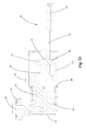
- each of the first grippers 7 has three first arms 9, the projections of two of which are situated in the plane of lie ⁇ , substantially coinciding and intersecting with the projection of the other first arm 9.
- two first arms 9 which are constrained to the same first pin 10 with a first axis Y' are envisaged. In functional terms, during opening and closing of the first gripper 7, these two first arms 9 rotate simultaneously in the same direction about the same first pin 10.
- the remaining first arm 9, the projection of which intersects that of the other two arms, is pivotably mounted on a different first pin 10 with a first axis Y and is arranged in between the other two arms in the direction defined by the first parallel axes Y, Y'.
- this latter first arm 9 is intended to rotate about the first axis Y in the opposite direction to the other two arms so as to move its first retaining portion 13 towards or away from that of the other two first arms 9 in order to cause closing or opening of the first gripper 7.
- all three first arms 9 of the same first gripper 7 are constrained together by the first actuating element 14 engaged inside their slots 15.
- the opening and closing movement of the first grippers 7 is produced by the displacement of the first actuating element 14 in the radial direction R in accordance with the same operating principle described above for the first embodiment.
- the slot 15 extends with an elongated form along the extension of the first arm 9 preferably along an initial section 21 from the constrained end 17 so as to keep the first actuating element 14 close to the first pins 10 of the first arms 9.
- This arrangement is such that a relatively short displacement of the first actuating element 14 causes a broad rotation of the first arms 9, thereby ensuring rapid opening and closing of the first gripper 7 when the containers 2 are released and picked up.
- first grippers 7 which are able to open and close with great rapidity so as to ensure immediate release of the container 2 following the displacement of the first actuating element 14 by the first actuator means 12.
- this characteristic feature is particularly advantageous also for the release of a container on any conveying means, such as conveyor belts, screw feeders or recessed starwheels, or during pick-up of the container.
- the first retaining portions 13 of each of the first arms 9 have a first projecting section 18 which is formed in the vicinity of the free end 16 and is slightly tapered from this end and a second step-like projecting section 19 with a first flat surface 75 arranged in an intermediate position between the first projecting section 18 and the slot 15.
- These projecting sections 18, 19 define between them an intermediate depressed section 20 which has a second flat surface 76 substantially parallel to the first surface 75.
- the first projecting section 18 and the depressed section 20 of each first retaining portion 13 are intended to grip the convexities or the corners of containers 2 which have a base of small width and varying shape, for example circular, rectangular or square shape.
- the second projecting section 19 is able to grip large-size containers 2 so as to ensure that they are retained, in cooperation with the first projecting section 18 or with the depressed section 20.
- the second projecting section 19 is also intended to grip the corners of containers 2 which have a polygonal base, in particular a triangular, rectangular or square base.
- the first retaining portions 13 of the first arms 9 are lined with a layer of plastic (not shown) able to adapt the first retaining portions 13 perfectly to the shape of the container 2 which rests against them so as to improve gripping thereof and avoid any risk of damage to the container 2 itself.
- a third projecting section 77 is envisaged, this being arranged between the first projecting section 18 and second projecting section 19 so as to form a further contact point during gripping of containers which have a particular shape and size.
- the first arms 9 may be disassembled and separated from the corresponding first grippers 7 so as to allow the bottling plant to function without the container conveying apparatus 1 and in operating conditions where the passage of the containers arranged, for example, on conveyor belts would interfere with the gripper arms.
- the abovementioned first arms 9 are each formed by a front section 21 and by an end section 81 which are removably connected together.
- the front section 21 is provided with a seat 78 inside which an end portion 81' of the end section 81 of the first arm 9 engages.
- the seat 78 has a flattened form and is defined by horizontal and parallel walls 79. Once inserted inside the seat 78 with its end portion 81' arranged between the two walls 79, the end section 81 of the first arm 9 is fixed to the front section 21 for example by means of a first screw 82 which is engaged inside first aligned through-holes formed in the walls 79 of the guide 78 and in the end portion 81'.
- a first screw 82 which is engaged inside first aligned through-holes formed in the walls 79 of the guide 78 and in the end portion 81'.
- the first actuator means 12 comprise a first cam 22 which is fixed to the support structure, coaxially with the first shaft 5.
- a first cam follower 23 is coupled with the first cam 22, being mounted on the first actuating element 14 engaged inside the slot 15 of the first arms 9.
- the first cam 22 is fixed to the fixed cylindrical body 4 for example by means of screws.
- said cam has the form of a ring with an inner perimetral profile 24 shaped with a first projecting segment 25, which interacts with the first cam follower 23 so as to bring the first grippers 7 into the first open position, and a second recessed segment 26, which interacts with the cam follower 23 so as to bring the first grippers 7 into the first closed position.
- first resilient means 27 are envisaged, these being connected to the actuator means 12 and exerting a permanent radial thrust on the first actuating element 14 in order to press the first cam follower 23 against the profile of the first cam 22.
- the first actuator means 12 comprise, for each first gripper 7, a first box-shaped body 28 which is fixed underneath the plates 8 of the first turntable 6 which keep the first grippers 7 opposite the slots 15 formed in the first arms 9 and with its first side 29 adjacent to the bottom plate 8.
- the first box-shaped body 28 has a first opening 30, formed in the first side 29, and a second opening 31, formed in a second side 32, opposite to the first side, both being aligned with the slots 15 in the first arms 9.
- These openings 30, 31 are passed through by the first actuating element 14 which advantageously consists of a first rod which is parallel to the vertical axis Z and which projects with its bottom end 33 from the second opening 31 in the first box-shaped body 28.
- This bottom end 33 has, rotatably and idly mounted thereon, the first cam follower 23 which preferably consists of a roller wheel or a bearing.
- the first and second openings 30, 31 have an elongated form so as to allow radial displacement of the first actuating element 14.
- the first aforementioned resilient means 27 comprise a first spring 34, preferably of the spiral type, housed inside the first box-shaped body 28 in a radially extending direction with respect to the first turntable 6. Said spring is compressed between the bottom 35 of the first box-shaped body 28 and a seat 36 formed at the end of a plug 37 slidably engaged inside the first box-shaped body 28.
- the plug 37 has a second transverse through-hole 150 aligned with the openings 30, 31 in the first box-shaped body 28 and with the slots 15 in the first arms 9, which second through-hole 150 is passed through by the first actuating element 14 so as to transfer to the latter the radial thrust exerted by the spring 34 and keep the first cam follower 23 pressed against the profile of the first cam 22.
- the plug 37 is engaged inside the first box-shaped body 28 by means of a third opening 38 formed in a third side 39 perpendicular to the first side and the second side 29, 32 of the said first box-shaped body 28.
- the first cam 22 may have several projecting and/or recessed segments in order to perform opening and closing of the first grippers 7 several times.
- the position of the segments 25 and 26 of the first cam 22 is designed to release and pick up the containers 2 correctly relative to the arrangement of the operating machines and the conveyors with which the apparatus 1 is intended to co-operate.
- the apparatus 1 for transferring containers 2 comprises a second turntable 41 coaxially fixed to a second shaft 42, substantially parallel to the first turntable 6, and arranged at a distance from the latter along the vertical axis Z.
- the second shaft 42 is coaxially engaged inside the first shaft 5 and rotatably constrained thereto.
- the second shaft 42 is connected to the first shaft 5 by means of a tongue-like part 43 for transmitting the rotational movement so as to allow the second shaft 42 to rotate about the vertical shaft Z integrally with the first shaft 5.
- the tongue-like part 43 allows the second shaft 42 to slide axially with respect to the first shaft 5, thereby allowing the vertical position of the second turntable 41 to be adjusted, as will be explained in detail below.
- the second turntable 41 has, peripherally mounted thereon at equally spaced intervals, a plurality of second grippers 44 aligned axially with the corresponding first grippers 7 of the first turntable 6 so as to co-operate during gripping of the same container 2.
- the second turntable 41 has a pair of parallel and horizontal discs 58 which are fixed to the second shaft 42 and on which the second grippers 44 are mounted, being arranged between the two said discs 58.
- a fixed cover 59 is also provided, being arranged parallel to the discs 58 and secured by means of an anti-rotation bracket 62 to a support bar 61 of the support structure, as shown, for example, in the embodiment according to Figures 1 and 2 .
- Each second gripper 44 has at least one pair of second arms 46 constrained to the second turntable 41 by means of corresponding second pins of 47 with second parallel axes. These second arms 46 can be actuated by second actuator means 48 so as to rotate about their second parallel axes between at least one second open position, where respective second retaining portions 49 of the second arms 46 are spaced from each other so as to receive or release the containers 2, and at least one second closed position, where the second retaining portions 49 are close together so as to hold the containers 2 between them.
- the first grippers 7 are advantageously intended to grip the containers 2 around their wide body part 73, while the second grippers 44 intended to retain the grippers 2 always in the region of their neck 74 so as to ensure centring of the mouth of the containers 2 with the heads of the operating machines or correctly position the containers 2 in other conveying means situated further downstream.
- the apparatus 1 comprises regulating means 50 able to slidably move the second shaft 42 along the vertical axis Z so as to vary the vertical position of the second turntable 41 relative to the first turntable 6.
- the regulating means 50 comprise a gear motor 51 which is fixed to the support structure of the apparatus 1.
- the gear motor 51 is connected to a threaded transmission rod 52 engaged inside a counter-threaded bush 80 which has, integrally fixed thereto, a movable base 53 connected by means of second bearings to the bottom end of the second shaft 42 on which the second turntable 41 is mounted.
- Figure 4 shows two different operating conditions of the apparatus 1, where the second turntable 41 is arranged at two different heights along the vertical axis Z so as to allow the second grippers 44 to retain, by means of their neck 74, containers 2 of two different sizes.
- each second arm 46 of each second gripper 44 is provided with a seat 55 which is arranged in the vicinity of the respective second pin 47 and which receives, engaged therein, a second actuating element 54 movable radially by the second actuator means 48 so as to cause rotation of the second arms 46.
- each second arm 46 has a shaped plate-like element 63 which is fixed thereto in the region of the second pin 47 and in which the seat 55, preferably with a substantially semi-circular shape, is formed.
- the two shaped plate-like elements 65 of the two second arms 46 of a same second gripper 44 are arranged in two different planes parallel to the horizontal plane of lie ⁇ . Said elements are partially superimposed with their recesses 55 arranged opposite each other so as to allow engagement of the second actuating element 54 therewith.
- the second actuator means 48 comprise a second cam 56 integrally connected to the support structure, arranged coaxially with the second shaft 42 and having, coupled therewith, a second cam follower 57 mounted on the second actuating element 54.
- this second cam 56 is fixed to the cover 59 of the second turntable 41.
- the profile of the second cam 56 is shaped so as to cause opening and closing of each second gripper 44 in a manner which is perfectly synchronized with the corresponding first gripper 7 with which it cooperates in order to retain the said container 2.
- second resilient means are provided so as to exert a radial thrust on the second actuating element 54, pressing the second cam follower 57 against the profile of said second cam 56.
- the second actuator means 48 comprise a second box-shaped body 64 which is provided, on two of its opposite sides, with four oppositely facing openings 65 which are aligned vertically and have a radially elongated form and inside which the second actuating element 54 is intended to be displaced.
- Said second actuating element 54 is connected to the second cam follower 57 by means of a horizontal pin 66 able to slide inside the second box-shaped body 64 integrally with the said second actuating element 54.
- the second actuating element 54 is formed by a second screw which engages inside a first threaded hole formed transversely in the pin 66.
- the second cam follower 57 consists of a roller or bearing mounted idle on a third pin 83 screwed rigidly inside a second threaded hole provided on the inner end 84 of the pin 66.
- the second resilient means comprise a second spring 67, which is preferably of the spiral type, compressed between a first shoulder 68 formed in the second box-shaped body 64 and a second shoulder 69 formed on the periphery of the pin 66, so as to keep the second cam follower 57 pressed against the outer edge of the second cam 56.
- the second arms 46 of the second grippers 44 are engaged directly inside a recess 85 formed in the second box-shaped body 64 and constrained thereto by means of the second pins 47.
- the second actuating element 54 consists of an elongated body, preferably made of tempered steel, with a circular cross-section and radially slidable inside the second box-shaped body 64. As shown in detail in Figures 23 and 25 , this second actuating element 54 has, at an outer end 86 thereof, a mushroom-shaped head 87 intended to engage inside seats 55 of the shaped plate-like elements 63 of the second arms 46.
- the aforementioned second elongated actuating element 54 has an elongated form owing to a shank 88 which is suitably connected with a substantially frustoconical part 88' to the head 87 so as to prevent the shaped plate-like elements 63 of the second arms 46 from interfering with the second actuating element 54 during the operations for opening and closing the second grippers 44.
- the shaped plate-like elements 63 move in a same horizontal plane and are suitably spaced so as not to hinder each other during their movement.
- the second spring 67 of the second resilient means acts on the second actuating element 54.
- the said second spring 67 is arranged between the first shoulder 68, formed in the second box-shaped body 64, and the second shoulder 69, formed peripherally in the second actuating element 54.
- the second spring 67 thus mounted presses the second cam follower 57 against the profile of the second cam 56, transmitting the thrust via the third pin 83.
- the second turntable 41 comprises a single disc 58 on which the second grippers 44 are mounted.
- This disc 58 is provided with a plurality of shaped openings 89 which, in number, are equal to the number of second grippers 44, the function of which is clarified hereinbelow.
- each assembly 160 carrying a second gripper 44 it is merely required to pass, by means of vertical displacement, the second cam follower 57 through a first wider section 90 of the shaped opening 89 and then move horizontally the assembly 160 so as to engage a second section 91 of the shaped opening 89, which has a width smaller then diameter of the cam follower 57, with a section of the third pin 83 situated underneath the second cam follower 57.
- the assembly 160 is fixed to the disc 58 of the second turntable 41 and held in position by means of third screws 92 which are inserted in corresponding third through-holes formed in the disc 58 itself.
- the displacement of the second cam follower 57 is such as to limit the sliding movement of the third pin 83 inside the second section 91 of the shaped openings 89.
- the second retaining portions 49 of the second arms 46 define concave oppositely facing profiles which are intended to receive and support the neck 74 of the container 2 at at least two contact points.
- These oppositely facing concave profiles are shaped in the manner of an envelope generated by the points of tangency with the neck 74 of the containers 2, upon variation of the diameter of their neck 74, when, obviously, the second grippers 44 are in the second closed position.
- the second retaining portions 49 of the second grippers 44 are shaped so as to retain necks with a substantially cylindrical or frustoconical shape having a diameter which is variable as per the main formats of commercially available containers.
- the second retaining portions 49 are lined with plastic or provided with rubber components in order to improve their grip with the neck 74 of the containers 2.
- the second gripper 44 is arranged with its second arms 46 closed so as to retain the neck 74 of a container 2 with a relatively large diameter (for example 40 millimetres).
- the container is retained between the second retaining portions 49, making contact with two different contact points on the latter, in particular a first contact point is situated on the first gripping section 70, while a second contact point is situated on the second gripping section 71.
- the second gripper 44 is arranged so as to retain a container 2 with a particularly narrow neck 74 (for example, diameter of 20 millimetres).
- neck 74 of the container 2 rests with its convex perimetral section against the depression 72 which embraces partially this perimetral section, ensuring a good retaining action and correct centring.
Landscapes
- Engineering & Computer Science (AREA)
- Mechanical Engineering (AREA)
- Specific Conveyance Elements (AREA)
- Filling Of Jars Or Cans And Processes For Cleaning And Sealing Jars (AREA)
- Control And Other Processes For Unpacking Of Materials (AREA)
- Container Filling Or Packaging Operations (AREA)
- Supplying Of Containers To The Packaging Station (AREA)
Applications Claiming Priority (1)
| Application Number | Priority Date | Filing Date | Title |
|---|---|---|---|
| ITPD2008A000331A IT1391818B1 (it) | 2008-11-13 | 2008-11-13 | Apparecchiatura per il trasferimento di contenitori |
Publications (2)
| Publication Number | Publication Date |
|---|---|
| EP2186759A1 true EP2186759A1 (de) | 2010-05-19 |
| EP2186759B1 EP2186759B1 (de) | 2012-01-04 |
Family
ID=41211215
Family Applications (1)
| Application Number | Title | Priority Date | Filing Date |
|---|---|---|---|
| EP09175852A Active EP2186759B1 (de) | 2008-11-13 | 2009-11-12 | Vorrichtung zum Versetzen von Behältern |
Country Status (5)
| Country | Link |
|---|---|
| US (1) | US8002107B2 (de) |
| EP (1) | EP2186759B1 (de) |
| AT (1) | ATE539988T1 (de) |
| ES (1) | ES2379508T3 (de) |
| IT (1) | IT1391818B1 (de) |
Cited By (14)
| Publication number | Priority date | Publication date | Assignee | Title |
|---|---|---|---|---|
| EP2332867A1 (de) * | 2009-12-14 | 2011-06-15 | Krones AG | Vorrichtung und Verfahren zum Transportieren von Behältnissen mit Bodenführung |
| EP2460746A1 (de) * | 2010-12-04 | 2012-06-06 | Krones AG | Fördervorrichtung für Behältnisse |
| EP2703322A1 (de) * | 2012-08-31 | 2014-03-05 | Krones AG | Greifeinrichtung zum Greifen von Behältnissen |
| CN104108601A (zh) * | 2013-04-22 | 2014-10-22 | 克朗斯股份公司 | 能调整的夹子星形装置 |
| ITBO20130210A1 (it) * | 2013-05-08 | 2014-11-09 | Effemmeit S R L | Gruppo di presa e trasferimento di contenitori in una macchina imbottigliatrice |
| WO2015036216A1 (de) * | 2013-09-12 | 2015-03-19 | Khs Gmbh | Transportrad sowie transportsystem |
| EP3239078A1 (de) * | 2016-04-28 | 2017-11-01 | Tyrolon-Schulnig GmbH | Höhenverstellvorrichtung für eine greif- und transporteinrichtung zum greifen, halten, führen und transportieren von insbesondere flaschenartigen behältern |
| WO2017188806A1 (es) * | 2016-04-28 | 2017-11-02 | AGUIRRE CLEMENTE, Nabor Blas | Ensamble de pieza de cambio ajustable para transmisión, transferencia y manejo de diferentes tipos y tamaños de envases o recipientes en una linea de producción |
| WO2018054592A1 (de) * | 2016-09-26 | 2018-03-29 | Khs Gmbh | Transportvorrichtung mit einem behältergreifer mit spindelantrieb |
| CN107922128A (zh) * | 2015-07-31 | 2018-04-17 | Ave技术有限责任公司 | 用于移动容器的设备 |
| WO2018162097A1 (de) * | 2017-03-09 | 2018-09-13 | Tyrolon-Schulnig Gmbh | Höhenverstellvorrichtung für eine greif- und transporteinrichtung für behälter |
| IT201700041639A1 (it) * | 2017-04-13 | 2018-10-13 | M C Automations S R L | Dispositivo di trasferimento per macchine incartatrici di prodotti dolciari |
| IT201800003295A1 (it) * | 2018-03-06 | 2019-09-06 | Smi Spa | Dispositivo di manipolazione di contenitori dotato di pinze ad apertura comandata |
| EP3613683A1 (de) * | 2018-08-22 | 2020-02-26 | Kematec Kellereitechnik GmbH | Greifereinheit |
Families Citing this family (19)
| Publication number | Priority date | Publication date | Assignee | Title |
|---|---|---|---|---|
| US8418836B2 (en) | 2010-05-07 | 2013-04-16 | The Procter & Gamble Company | Universally adjustable star wheel |
| US8813950B2 (en) | 2010-05-07 | 2014-08-26 | The Procter & Gamble Company | Automated adjustment system for star wheel |
| DE102011116883A1 (de) * | 2011-04-21 | 2012-10-25 | Khs Corpoplast Gmbh | Vorrichtung zur Halterung von Werkstücken |
| DE102013113292A1 (de) * | 2013-12-02 | 2015-06-18 | Khs Gmbh | Transportstern mit verstellbaren Sterntaschen |
| DE102014101959A1 (de) | 2014-02-17 | 2015-08-20 | Khs Gmbh | Werkzeuglos befestigter Schutzkörper zum Schutz von Glasflaschen in Sterntaschen |
| US9371195B2 (en) | 2014-06-03 | 2016-06-21 | The Procter & Gamble Company | Adjustment system for a rotary device |
| US9302856B2 (en) * | 2014-06-03 | 2016-04-05 | The Procter & Gamble Company | Method for adjusting a rotary device |
| CN106458475B (zh) * | 2014-06-11 | 2019-11-26 | 利乐拉瓦尔集团及财务有限公司 | 传送装置 |
| CN104477580A (zh) * | 2014-12-03 | 2015-04-01 | 重庆市合川区均恒金属加工厂 | 送料圆盘 |
| DE102015114567B4 (de) * | 2015-09-01 | 2020-08-13 | Tyrolon-Schulnig Gmbh | Einsetzbare Ansteuerungsvorrichtung und Transportvorrichtung für Behälter, sowie schwebend positionierte Ansteuerungsvorrichtung |
| US10315860B2 (en) | 2016-05-25 | 2019-06-11 | The Procter And Gamble Company | Article handling device |
| US10669107B2 (en) | 2017-03-09 | 2020-06-02 | Tyrolon-Schulnig Gmbh | Carrying apparatus and cam control shaft for gripping devices |
| DE102017105024B4 (de) | 2017-03-09 | 2021-02-11 | Tyrolon-Schulnig Gmbh | Rinsersystem |
| US20190031380A1 (en) * | 2017-07-25 | 2019-01-31 | Exxonmobil Research And Engineering Company | Automated changing of supports for different sized containers in a container filling system |
| CN109231118A (zh) * | 2018-10-08 | 2019-01-18 | 广州达意隆包装机械股份有限公司 | 一种瓶夹及灌装机 |
| CN109368152A (zh) * | 2018-11-01 | 2019-02-22 | 常州机电职业技术学院 | 一种工件方位不变的转运机构 |
| US11713145B2 (en) * | 2019-03-04 | 2023-08-01 | Illinois Tool Works Inc. | Variable pitch starwheel for container carrier applicating machine |
| DE102019131587A1 (de) * | 2019-11-22 | 2021-05-27 | Krones Aktiengesellschaft | Klammervorrichtung zum Halten eines Behälters |
| CN114473608A (zh) * | 2022-02-23 | 2022-05-13 | 湖北锐仕拓机电设备有限公司 | 一种水箱外壳加工用上下料设备及其加工方法 |
Citations (4)
| Publication number | Priority date | Publication date | Assignee | Title |
|---|---|---|---|---|
| FR910315A (fr) * | 1945-04-23 | 1946-06-04 | Remplisseuse boucheuse de flacons | |
| JPS5939614A (ja) * | 1982-08-30 | 1984-03-05 | Shibuya Kogyo Co Ltd | 容器の方向揃え装置 |
| EP0366225A1 (de) | 1988-10-26 | 1990-05-02 | Shibuya Kogyo Co., Ltd | Übergabevorrichtung für Gegenstände mit Greifer |
| DE19903319A1 (de) * | 1998-02-18 | 1999-08-19 | Tincati | Flaschenzu- und -abführdrehstern mit Zellen veränderbarer Abmessungen, insbesondere für automatische Abfüllmaschinen |
Family Cites Families (7)
| Publication number | Priority date | Publication date | Assignee | Title |
|---|---|---|---|---|
| DE4436717C1 (de) * | 1994-10-14 | 1996-04-04 | Schmermund Maschf Alfred | Förderer zum Zusammenpressen von Zigarettenblöcken |
| ES2124956T3 (es) * | 1995-02-07 | 1999-02-16 | Hermann Kronseder | Estrella de transporte para recipientes. |
| US6691860B2 (en) * | 2000-11-09 | 2004-02-17 | Honeywell International Inc. | Gripper mechanism for handling a cylindrical workpiece |
| US6557695B2 (en) * | 2001-08-01 | 2003-05-06 | Owens-Brockway Glass Container Inc. | Apparatus and method for inspecting non-round containers |
| DE10206634A1 (de) * | 2002-02-12 | 2003-08-28 | Krones Ag | Fördervorrichtung |
| FR2881677B1 (fr) * | 2005-02-08 | 2007-04-27 | Sidel Sas | Dispositif rotatif de transfert de recipients |
| FR2907438B1 (fr) * | 2006-10-20 | 2009-01-16 | Sidel Participations | Procede et installation de changement de pas d'entites discretes convoyees les unes a la suite des autres |
-
2008
- 2008-11-13 IT ITPD2008A000331A patent/IT1391818B1/it active
-
2009
- 2009-11-12 AT AT09175852T patent/ATE539988T1/de active
- 2009-11-12 EP EP09175852A patent/EP2186759B1/de active Active
- 2009-11-12 ES ES09175852T patent/ES2379508T3/es active Active
- 2009-11-13 US US12/617,831 patent/US8002107B2/en active Active
Patent Citations (4)
| Publication number | Priority date | Publication date | Assignee | Title |
|---|---|---|---|---|
| FR910315A (fr) * | 1945-04-23 | 1946-06-04 | Remplisseuse boucheuse de flacons | |
| JPS5939614A (ja) * | 1982-08-30 | 1984-03-05 | Shibuya Kogyo Co Ltd | 容器の方向揃え装置 |
| EP0366225A1 (de) | 1988-10-26 | 1990-05-02 | Shibuya Kogyo Co., Ltd | Übergabevorrichtung für Gegenstände mit Greifer |
| DE19903319A1 (de) * | 1998-02-18 | 1999-08-19 | Tincati | Flaschenzu- und -abführdrehstern mit Zellen veränderbarer Abmessungen, insbesondere für automatische Abfüllmaschinen |
Cited By (29)
| Publication number | Priority date | Publication date | Assignee | Title |
|---|---|---|---|---|
| EP2332867A1 (de) * | 2009-12-14 | 2011-06-15 | Krones AG | Vorrichtung und Verfahren zum Transportieren von Behältnissen mit Bodenführung |
| US20110138613A1 (en) * | 2009-12-14 | 2011-06-16 | Wolfgang Hahn | Apparatus and method of conveying containers with base guidance |
| US9090408B2 (en) | 2009-12-14 | 2015-07-28 | Krones Ag | Apparatus and method of conveying containers with base guidance |
| EP2460746A1 (de) * | 2010-12-04 | 2012-06-06 | Krones AG | Fördervorrichtung für Behältnisse |
| EP2703322A1 (de) * | 2012-08-31 | 2014-03-05 | Krones AG | Greifeinrichtung zum Greifen von Behältnissen |
| CN103662826A (zh) * | 2012-08-31 | 2014-03-26 | 克朗斯股份有限公司 | 用于夹持容器的夹持装置 |
| DE102013207267A1 (de) | 2013-04-22 | 2014-10-23 | Krones Ag | Verstellbarer Klammerstern |
| EP2796394A1 (de) * | 2013-04-22 | 2014-10-29 | Krones AG | Verstellbarer Klammerstern |
| CN104108601A (zh) * | 2013-04-22 | 2014-10-22 | 克朗斯股份公司 | 能调整的夹子星形装置 |
| ITBO20130210A1 (it) * | 2013-05-08 | 2014-11-09 | Effemmeit S R L | Gruppo di presa e trasferimento di contenitori in una macchina imbottigliatrice |
| WO2015036216A1 (de) * | 2013-09-12 | 2015-03-19 | Khs Gmbh | Transportrad sowie transportsystem |
| CN105555682A (zh) * | 2013-09-12 | 2016-05-04 | Khs有限责任公司 | 传送轮和传送系统 |
| US9688484B2 (en) | 2013-09-12 | 2017-06-27 | Khs Gmbh | Conveying wheel and conveying system |
| CN105555682B (zh) * | 2013-09-12 | 2017-09-12 | Khs有限责任公司 | 传送轮和传送系统 |
| US10308443B2 (en) | 2015-07-31 | 2019-06-04 | Ave Technologies S.R.L. | Apparatus for the movement of containers |
| CN107922128A (zh) * | 2015-07-31 | 2018-04-17 | Ave技术有限责任公司 | 用于移动容器的设备 |
| EP3239078A1 (de) * | 2016-04-28 | 2017-11-01 | Tyrolon-Schulnig GmbH | Höhenverstellvorrichtung für eine greif- und transporteinrichtung zum greifen, halten, führen und transportieren von insbesondere flaschenartigen behältern |
| WO2017188806A1 (es) * | 2016-04-28 | 2017-11-02 | AGUIRRE CLEMENTE, Nabor Blas | Ensamble de pieza de cambio ajustable para transmisión, transferencia y manejo de diferentes tipos y tamaños de envases o recipientes en una linea de producción |
| WO2018054592A1 (de) * | 2016-09-26 | 2018-03-29 | Khs Gmbh | Transportvorrichtung mit einem behältergreifer mit spindelantrieb |
| EP3515846A1 (de) * | 2016-09-26 | 2019-07-31 | KHS GmbH | Transportvorrichtung mit einem behältergreifer mit spindelantrieb |
| WO2018162097A1 (de) * | 2017-03-09 | 2018-09-13 | Tyrolon-Schulnig Gmbh | Höhenverstellvorrichtung für eine greif- und transporteinrichtung für behälter |
| US10870544B2 (en) | 2017-03-09 | 2020-12-22 | Tyrolon-Schulnig Gmbh | Height-adjusting device for a gripping and transporting means for containers |
| WO2018189763A1 (en) * | 2017-04-13 | 2018-10-18 | M.C. Automations S.R.L. | Transfer device for wrapping machines for confectionery products |
| IT201700041639A1 (it) * | 2017-04-13 | 2018-10-13 | M C Automations S R L | Dispositivo di trasferimento per macchine incartatrici di prodotti dolciari |
| IT201800003295A1 (it) * | 2018-03-06 | 2019-09-06 | Smi Spa | Dispositivo di manipolazione di contenitori dotato di pinze ad apertura comandata |
| EP3536638A1 (de) * | 2018-03-06 | 2019-09-11 | Smi S.P.A. Con Socio Unico | Handhabungsvorrichtung für behälter mit klammern zum öffnen auf befehl |
| US20190276175A1 (en) * | 2018-03-06 | 2019-09-12 | Smi S.P.A. Con Socio Unico | Handling device for containers provided with clamps for opening on command |
| CN110228703A (zh) * | 2018-03-06 | 2019-09-13 | Smi单一股东有限责任公司 | 设置有按命令打开的夹具的容器处理装置 |
| EP3613683A1 (de) * | 2018-08-22 | 2020-02-26 | Kematec Kellereitechnik GmbH | Greifereinheit |
Also Published As
| Publication number | Publication date |
|---|---|
| US8002107B2 (en) | 2011-08-23 |
| ATE539988T1 (de) | 2012-01-15 |
| ITPD20080331A1 (it) | 2010-05-14 |
| EP2186759B1 (de) | 2012-01-04 |
| US20110114454A1 (en) | 2011-05-19 |
| IT1391818B1 (it) | 2012-01-27 |
| ES2379508T3 (es) | 2012-04-26 |
Similar Documents
| Publication | Publication Date | Title |
|---|---|---|
| US8002107B2 (en) | Apparatus for transferring containers | |
| EP2566792B1 (de) | Einstellbares sternrad | |
| EP3907162A1 (de) | Anlage zur verarbeitung von behältern | |
| AU626730B2 (en) | Continuous to intermittent feeding interface | |
| US9090408B2 (en) | Apparatus and method of conveying containers with base guidance | |
| EP1426313A1 (de) | Übertragungsvorrichtung für Behälter | |
| EP2248759B1 (de) | Behälterbehandlungsmaschine, insbesondere in einer Abfüllanlage für Nahrungsmittel | |
| MX2011002088A (es) | Metodo y dispositivo para la colocacion de recipientes y planta para tratar recipientes que tienen diferentes secciones transversales. | |
| US4817363A (en) | Fitment inserter machine | |
| EP1597150B1 (de) | Vorrichtung zum formen von behältern | |
| US3587816A (en) | Mechanism for removing containers from mandrels | |
| EP2438000A1 (de) | Maschine zum verschliessen von behältern | |
| EP1273551B1 (de) | Verschliesseinrichtung mit einem Verschliesskopf | |
| EP3162721A1 (de) | Vorrichtung zur handhabung von behältern | |
| KR100189206B1 (ko) | 판상 물체의 파지 작용을 제어하기 위한 장치 | |
| CN115367687A (zh) | 用于封闭容器的封盖装置和封盖机 | |
| CN113307202B (zh) | 一种回转式旋盖机 | |
| JPH04279493A (ja) | 容器に栓をするための装置 | |
| CN115973985B (zh) | 一种回转式夹桶机构 | |
| JPS6114970Y2 (de) | ||
| CN220317359U (zh) | 一种新型的直线旋盖机 | |
| EP0918037B1 (de) | Maschine für die wahlweise Abgabe von Vier-Draht oder Brücken-Typ- Käfigen zur Sicherung von Korken für Schaumweinflaschen | |
| EP2735529B1 (de) | Artikelausgerichteter Sternradförderer, insbesondere für Etikettiermaschinen | |
| JP2005200180A (ja) | 自動作業用グリップ装置 | |
| JP2004517009A (ja) | 移動式シールステーションへのメンブレンシール供給装置 |
Legal Events
| Date | Code | Title | Description |
|---|---|---|---|
| PUAI | Public reference made under article 153(3) epc to a published international application that has entered the european phase |
Free format text: ORIGINAL CODE: 0009012 |
|
| AK | Designated contracting states |
Kind code of ref document: A1 Designated state(s): AT BE BG CH CY CZ DE DK EE ES FI FR GB GR HR HU IE IS IT LI LT LU LV MC MK MT NL NO PL PT RO SE SI SK SM TR |
|
| AX | Request for extension of the european patent |
Extension state: AL BA RS |
|
| 17P | Request for examination filed |
Effective date: 20101117 |
|
| 17Q | First examination report despatched |
Effective date: 20110406 |
|
| GRAP | Despatch of communication of intention to grant a patent |
Free format text: ORIGINAL CODE: EPIDOSNIGR1 |
|
| GRAS | Grant fee paid |
Free format text: ORIGINAL CODE: EPIDOSNIGR3 |
|
| GRAA | (expected) grant |
Free format text: ORIGINAL CODE: 0009210 |
|
| AK | Designated contracting states |
Kind code of ref document: B1 Designated state(s): AT BE BG CH CY CZ DE DK EE ES FI FR GB GR HR HU IE IS IT LI LT LU LV MC MK MT NL NO PL PT RO SE SI SK SM TR |
|
| REG | Reference to a national code |
Ref country code: GB Ref legal event code: FG4D |
|
| REG | Reference to a national code |
Ref country code: CH Ref legal event code: EP |
|
| REG | Reference to a national code |
Ref country code: AT Ref legal event code: REF Ref document number: 539988 Country of ref document: AT Kind code of ref document: T Effective date: 20120115 |
|
| REG | Reference to a national code |
Ref country code: IE Ref legal event code: FG4D |
|
| REG | Reference to a national code |
Ref country code: DE Ref legal event code: R096 Ref document number: 602009004488 Country of ref document: DE Effective date: 20120308 |
|
| REG | Reference to a national code |
Ref country code: ES Ref legal event code: FG2A Ref document number: 2379508 Country of ref document: ES Kind code of ref document: T3 Effective date: 20120426 |
|
| REG | Reference to a national code |
Ref country code: NL Ref legal event code: VDEP Effective date: 20120104 |
|
| PG25 | Lapsed in a contracting state [announced via postgrant information from national office to epo] |
Ref country code: SI Free format text: LAPSE BECAUSE OF FAILURE TO SUBMIT A TRANSLATION OF THE DESCRIPTION OR TO PAY THE FEE WITHIN THE PRESCRIBED TIME-LIMIT Effective date: 20120104 |
|
| LTIE | Lt: invalidation of european patent or patent extension |
Effective date: 20120104 |
|
| PG25 | Lapsed in a contracting state [announced via postgrant information from national office to epo] |
Ref country code: NL Free format text: LAPSE BECAUSE OF FAILURE TO SUBMIT A TRANSLATION OF THE DESCRIPTION OR TO PAY THE FEE WITHIN THE PRESCRIBED TIME-LIMIT Effective date: 20120104 Ref country code: IS Free format text: LAPSE BECAUSE OF FAILURE TO SUBMIT A TRANSLATION OF THE DESCRIPTION OR TO PAY THE FEE WITHIN THE PRESCRIBED TIME-LIMIT Effective date: 20120504 Ref country code: BG Free format text: LAPSE BECAUSE OF FAILURE TO SUBMIT A TRANSLATION OF THE DESCRIPTION OR TO PAY THE FEE WITHIN THE PRESCRIBED TIME-LIMIT Effective date: 20120404 Ref country code: LT Free format text: LAPSE BECAUSE OF FAILURE TO SUBMIT A TRANSLATION OF THE DESCRIPTION OR TO PAY THE FEE WITHIN THE PRESCRIBED TIME-LIMIT Effective date: 20120104 Ref country code: NO Free format text: LAPSE BECAUSE OF FAILURE TO SUBMIT A TRANSLATION OF THE DESCRIPTION OR TO PAY THE FEE WITHIN THE PRESCRIBED TIME-LIMIT Effective date: 20120404 Ref country code: BE Free format text: LAPSE BECAUSE OF FAILURE TO SUBMIT A TRANSLATION OF THE DESCRIPTION OR TO PAY THE FEE WITHIN THE PRESCRIBED TIME-LIMIT Effective date: 20120104 Ref country code: HR Free format text: LAPSE BECAUSE OF FAILURE TO SUBMIT A TRANSLATION OF THE DESCRIPTION OR TO PAY THE FEE WITHIN THE PRESCRIBED TIME-LIMIT Effective date: 20120104 |
|
| PG25 | Lapsed in a contracting state [announced via postgrant information from national office to epo] |
Ref country code: GR Free format text: LAPSE BECAUSE OF FAILURE TO SUBMIT A TRANSLATION OF THE DESCRIPTION OR TO PAY THE FEE WITHIN THE PRESCRIBED TIME-LIMIT Effective date: 20120405 Ref country code: LV Free format text: LAPSE BECAUSE OF FAILURE TO SUBMIT A TRANSLATION OF THE DESCRIPTION OR TO PAY THE FEE WITHIN THE PRESCRIBED TIME-LIMIT Effective date: 20120104 Ref country code: PT Free format text: LAPSE BECAUSE OF FAILURE TO SUBMIT A TRANSLATION OF THE DESCRIPTION OR TO PAY THE FEE WITHIN THE PRESCRIBED TIME-LIMIT Effective date: 20120504 Ref country code: PL Free format text: LAPSE BECAUSE OF FAILURE TO SUBMIT A TRANSLATION OF THE DESCRIPTION OR TO PAY THE FEE WITHIN THE PRESCRIBED TIME-LIMIT Effective date: 20120104 Ref country code: FI Free format text: LAPSE BECAUSE OF FAILURE TO SUBMIT A TRANSLATION OF THE DESCRIPTION OR TO PAY THE FEE WITHIN THE PRESCRIBED TIME-LIMIT Effective date: 20120104 |
|
| REG | Reference to a national code |
Ref country code: AT Ref legal event code: MK05 Ref document number: 539988 Country of ref document: AT Kind code of ref document: T Effective date: 20120104 |
|
| PG25 | Lapsed in a contracting state [announced via postgrant information from national office to epo] |
Ref country code: CY Free format text: LAPSE BECAUSE OF FAILURE TO SUBMIT A TRANSLATION OF THE DESCRIPTION OR TO PAY THE FEE WITHIN THE PRESCRIBED TIME-LIMIT Effective date: 20120104 |
|
| PG25 | Lapsed in a contracting state [announced via postgrant information from national office to epo] |
Ref country code: EE Free format text: LAPSE BECAUSE OF FAILURE TO SUBMIT A TRANSLATION OF THE DESCRIPTION OR TO PAY THE FEE WITHIN THE PRESCRIBED TIME-LIMIT Effective date: 20120104 Ref country code: CZ Free format text: LAPSE BECAUSE OF FAILURE TO SUBMIT A TRANSLATION OF THE DESCRIPTION OR TO PAY THE FEE WITHIN THE PRESCRIBED TIME-LIMIT Effective date: 20120104 Ref country code: RO Free format text: LAPSE BECAUSE OF FAILURE TO SUBMIT A TRANSLATION OF THE DESCRIPTION OR TO PAY THE FEE WITHIN THE PRESCRIBED TIME-LIMIT Effective date: 20120104 Ref country code: DK Free format text: LAPSE BECAUSE OF FAILURE TO SUBMIT A TRANSLATION OF THE DESCRIPTION OR TO PAY THE FEE WITHIN THE PRESCRIBED TIME-LIMIT Effective date: 20120104 Ref country code: SE Free format text: LAPSE BECAUSE OF FAILURE TO SUBMIT A TRANSLATION OF THE DESCRIPTION OR TO PAY THE FEE WITHIN THE PRESCRIBED TIME-LIMIT Effective date: 20120104 |
|
| PLBE | No opposition filed within time limit |
Free format text: ORIGINAL CODE: 0009261 |
|
| STAA | Information on the status of an ep patent application or granted ep patent |
Free format text: STATUS: NO OPPOSITION FILED WITHIN TIME LIMIT |
|
| PG25 | Lapsed in a contracting state [announced via postgrant information from national office to epo] |
Ref country code: SK Free format text: LAPSE BECAUSE OF FAILURE TO SUBMIT A TRANSLATION OF THE DESCRIPTION OR TO PAY THE FEE WITHIN THE PRESCRIBED TIME-LIMIT Effective date: 20120104 |
|
| 26N | No opposition filed |
Effective date: 20121005 |
|
| PG25 | Lapsed in a contracting state [announced via postgrant information from national office to epo] |
Ref country code: AT Free format text: LAPSE BECAUSE OF FAILURE TO SUBMIT A TRANSLATION OF THE DESCRIPTION OR TO PAY THE FEE WITHIN THE PRESCRIBED TIME-LIMIT Effective date: 20120104 |
|
| REG | Reference to a national code |
Ref country code: DE Ref legal event code: R097 Ref document number: 602009004488 Country of ref document: DE Effective date: 20121005 |
|
| REG | Reference to a national code |
Ref country code: IE Ref legal event code: MM4A |
|
| PG25 | Lapsed in a contracting state [announced via postgrant information from national office to epo] |
Ref country code: IE Free format text: LAPSE BECAUSE OF NON-PAYMENT OF DUE FEES Effective date: 20121112 |
|
| PG25 | Lapsed in a contracting state [announced via postgrant information from national office to epo] |
Ref country code: MT Free format text: LAPSE BECAUSE OF FAILURE TO SUBMIT A TRANSLATION OF THE DESCRIPTION OR TO PAY THE FEE WITHIN THE PRESCRIBED TIME-LIMIT Effective date: 20120104 |
|
| PG25 | Lapsed in a contracting state [announced via postgrant information from national office to epo] |
Ref country code: TR Free format text: LAPSE BECAUSE OF FAILURE TO SUBMIT A TRANSLATION OF THE DESCRIPTION OR TO PAY THE FEE WITHIN THE PRESCRIBED TIME-LIMIT Effective date: 20120104 Ref country code: MC Free format text: LAPSE BECAUSE OF NON-PAYMENT OF DUE FEES Effective date: 20121130 |
|
| PG25 | Lapsed in a contracting state [announced via postgrant information from national office to epo] |
Ref country code: SM Free format text: LAPSE BECAUSE OF FAILURE TO SUBMIT A TRANSLATION OF THE DESCRIPTION OR TO PAY THE FEE WITHIN THE PRESCRIBED TIME-LIMIT Effective date: 20120104 Ref country code: LU Free format text: LAPSE BECAUSE OF NON-PAYMENT OF DUE FEES Effective date: 20121112 |
|
| REG | Reference to a national code |
Ref country code: CH Ref legal event code: PL |
|
| PG25 | Lapsed in a contracting state [announced via postgrant information from national office to epo] |
Ref country code: LI Free format text: LAPSE BECAUSE OF NON-PAYMENT OF DUE FEES Effective date: 20131130 Ref country code: CH Free format text: LAPSE BECAUSE OF NON-PAYMENT OF DUE FEES Effective date: 20131130 Ref country code: HU Free format text: LAPSE BECAUSE OF FAILURE TO SUBMIT A TRANSLATION OF THE DESCRIPTION OR TO PAY THE FEE WITHIN THE PRESCRIBED TIME-LIMIT Effective date: 20091112 |
|
| PG25 | Lapsed in a contracting state [announced via postgrant information from national office to epo] |
Ref country code: MK Free format text: LAPSE BECAUSE OF FAILURE TO SUBMIT A TRANSLATION OF THE DESCRIPTION OR TO PAY THE FEE WITHIN THE PRESCRIBED TIME-LIMIT Effective date: 20120104 |
|
| REG | Reference to a national code |
Ref country code: FR Ref legal event code: PLFP Year of fee payment: 7 |
|
| REG | Reference to a national code |
Ref country code: FR Ref legal event code: PLFP Year of fee payment: 8 |
|
| REG | Reference to a national code |
Ref country code: FR Ref legal event code: PLFP Year of fee payment: 9 |
|
| PGFP | Annual fee paid to national office [announced via postgrant information from national office to epo] |
Ref country code: ES Payment date: 20230125 Year of fee payment: 14 |
|
| P01 | Opt-out of the competence of the unified patent court (upc) registered |
Effective date: 20230303 |
|
| PGFP | Annual fee paid to national office [announced via postgrant information from national office to epo] |
Ref country code: GB Payment date: 20231123 Year of fee payment: 15 |
|
| PGFP | Annual fee paid to national office [announced via postgrant information from national office to epo] |
Ref country code: IT Payment date: 20231129 Year of fee payment: 15 Ref country code: FR Payment date: 20231120 Year of fee payment: 15 Ref country code: DE Payment date: 20231121 Year of fee payment: 15 |
|
| PGFP | Annual fee paid to national office [announced via postgrant information from national office to epo] |
Ref country code: ES Payment date: 20240126 Year of fee payment: 15 |