EP2159352B1 - Zelt- oder Schutzdach - Google Patents
Zelt- oder Schutzdach Download PDFInfo
- Publication number
- EP2159352B1 EP2159352B1 EP09011076.8A EP09011076A EP2159352B1 EP 2159352 B1 EP2159352 B1 EP 2159352B1 EP 09011076 A EP09011076 A EP 09011076A EP 2159352 B1 EP2159352 B1 EP 2159352B1
- Authority
- EP
- European Patent Office
- Prior art keywords
- roof
- tent
- pendulum arm
- pendulum
- linkage
- Prior art date
- Legal status (The legal status is an assumption and is not a legal conclusion. Google has not performed a legal analysis and makes no representation as to the accuracy of the status listed.)
- Active
Links
Images
Classifications
-
- E—FIXED CONSTRUCTIONS
- E04—BUILDING
- E04H—BUILDINGS OR LIKE STRUCTURES FOR PARTICULAR PURPOSES; SWIMMING OR SPLASH BATHS OR POOLS; MASTS; FENCING; TENTS OR CANOPIES, IN GENERAL
- E04H15/00—Tents or canopies, in general
- E04H15/02—Tents combined or specially associated with other devices
- E04H15/06—Tents at least partially supported by vehicles
- E04H15/08—Trailer awnings or the like
-
- B—PERFORMING OPERATIONS; TRANSPORTING
- B60—VEHICLES IN GENERAL
- B60P—VEHICLES ADAPTED FOR LOAD TRANSPORTATION OR TO TRANSPORT, TO CARRY, OR TO COMPRISE SPECIAL LOADS OR OBJECTS
- B60P3/00—Vehicles adapted to transport, to carry or to comprise special loads or objects
- B60P3/32—Vehicles adapted to transport, to carry or to comprise special loads or objects comprising living accommodation for people, e.g. caravans, camping, or like vehicles
- B60P3/34—Vehicles adapted to transport, to carry or to comprise special loads or objects comprising living accommodation for people, e.g. caravans, camping, or like vehicles the living accommodation being expansible, collapsible or capable of rearrangement
- B60P3/341—Vehicles adapted to transport, to carry or to comprise special loads or objects comprising living accommodation for people, e.g. caravans, camping, or like vehicles the living accommodation being expansible, collapsible or capable of rearrangement comprising flexible elements
- B60P3/343—Hoods for caravans
Definitions
- the invention relates to a tent or protective roof in the form of a folding construction that can be transported with a camping trailer or similar camping vehicle.
- Folding structures that can be transported with a camping trailer and form a tent or protective roof have been known for a long time ( DE 28 41 550 ; US 7,178,536 B2 ), whereby a corresponding position of use is specified for a flexible roof skin by means of a respective linkage structure connected to the trailer.
- the support rods forming the linkage structure are provided in the form of essentially torsion-resistant pipe parts which are held by joint parts or similar connectors so that different use or non-use positions can be reached for such folding systems by a corresponding adjustment movement.
- a roof skin consisting of a special tent sheet is formed into desk-shaped, flat or angular wall sections by means of the essentially straight rod and tube parts. Due to this structure of the pole construction in the manner of a steep wall tent, the system is generally susceptible to wind and the inner usable space is narrowed in the vicinity of the pole and tube parts.
- a gable tent used as a simple work tent for utility companies is proposed, in which between two support rods one end is connected to the latter Transverse rod extends, which has respective kinks or an arcuate curvature in the longitudinal direction.
- This curved transverse rod which is to be connected at both ends with support rods, is intended to improve the applicability of simple tents on construction sites of utility companies.
- a part of the tarpaulin attached to a wall of the caravan is combined with a rod that can also be attached to the wall.
- This rod supported towards the floor area interacts with an additional rod crossing this, so that an arcuate alignment of the tarpaulin part is achieved and an awning with an arcuate side wall is formed between the caravan and the lateral floor area.
- U.S. 8,080,426 is a camping trailer disclosed with a tent that provides pivotable boom on the tent frame to expand the tent contour.
- the DE 202 16 105 shows a frame for a tent roof with which a canopy protruding over a tent wall can be realized.
- U.S. 5,449,032 shows a linkage for an arched, profiled canopy of a camping accommodation.
- the bow-shaped rod parts are telescopic.
- a framework which is also used in steep wall tents, is built from pipe and profile parts.
- a profile part shaped as an arched rod is provided for receiving a flexible plate as a cover part on the frame, which has recesses and holding parts for receiving the plate.
- the invention is concerned with the problem of creating a tent or protective roof which is intended in particular for a camping trailer as a transportable folding structure, which in the erected position of use forms a usable space from less wind-prone rod parts with little technical effort, while the roof skin dimensions remain essentially the same Has usable space and allows malleable expansion zones with a visually appealing roof contour.
- the invention provides that this folding system is supplemented by at least one additional pendulum arm that can be integrated into the rod assembly or the flexible roof membrane held by it.
- This pendulum arm is integrated into the system like an auxiliary rod, so that with the largely unchanged rod assembly - even in the version defined as heavy - respective functional and visually effective extension zones can be created on the tent roof with little effort.
- the concept of the pendulum arm is based on the fact that it defines a main connection point on at least one rod part and from this two arms each act as essentially freely protruding sub-areas below the roof skin, so that the arm system "pendulums" around the main connection point according to the rod assembly "can be set or, under the action of an external or internal load, performs a" pendulum "compensating movement.
- the pendulum arm according to the invention a simple and, in the application case, efficient solution for expanding the functions of camping trailer tents, family tents, Caravan awnings or the like. Constructions proposed.
- a known simple tent rod with essentially straight rods - which also allow quick folding assembly when setting up or dismantling by folding back into the area of the trailer - can be used unchanged with the known advantages in handling.
- the pendulum arm according to the invention as an additional component that can be used in variable sizes can be dimensioned in such a way that an additional arch shape corresponding to different customer requirements is generated in optically protruding areas of the roof skin.
- the roof skin which is largely unchanged in terms of its dimensions, can be relocated in such a way that a volume or space expansion is achieved in the usable space below and the comfort for the user is improved.
- one or more pendulum arm (s) of the auxiliary rod are integrated into the tent rod in such a way that an improved absorption of compressive and tensile loads in the area of the roof skin, for example from wind pressure, rainwater or the like, is achieved.
- the curved pendulum arms in the installation position create a contour that optimally adapts to the wind forces that occur, so that the system has improved storm resistance overall thanks to a wind-deflecting contour and optimal water drainage is guaranteed even in heavy rain.
- the pendulum arm structure which can be expanded as required, can be designed in such a way that the rod parts that have previously been used for awnings and sunroofs can be used o. The like. Be replaced by the new pendulum arms and so the number of components is reduced.
- the pendulum arm parts provided as auxiliary rods can also be built into or attached to the support rods designed as tubular parts so that they can be carried along as telescopic parts and pulled out into a corresponding position of use on site. It is also provided that the pendulum arms are attached as parts that can be aligned parallel to the rod parts, so that a tight packing position becomes possible when not in use or when in transit.
- a ridge pole of the folding linkage can be expanded in its area of use, with the pendulum arms designed as flexible parts in particular being positionable longitudinally or transversely to the central longitudinal axis and thus a large number of functional expansions in this roof area.
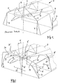
- Fig. 1 is illustrated in a perspective view of a camping assembly in which a camping trailer 1 accommodating a transportable folding structure is used.
- a tent or protective roof designated as a whole by 2
- This construction comes with a multiple rigid support rods 4, 5, 6 having and for a flexible roof skin 7 the position of use of the rod assembly 8 is provided.
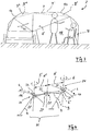
- the invention provides for this rod assembly 8 to be provided with at least one pendulum arm 9 profiling the roof skin 7 'in the installed position.
- the principle representation according to Fig. 2 This makes it clear that the pendulum arm 9, which has an arcuate profile in particular, defines a main connection point P, which can be implemented as a rigid or articulated bracket, towards the rod assembly 8, so that a "pendulum mobility" of the system is achieved, as indicated by dashed lines, and in this the pendulum arm 9 in the manner of an auxiliary rod H is effective.
- the linkage assembly 8 also has several pendulum arms 10, 11 ( Figures 3 to 6 ), 12 to 15 ( Fig. 7 ) and / or 16, 17 ( Fig. 8 ) can be provided.
- At 9 'another pendulum arm is connected to the support rods of the rod assembly 8 ( Fig. 2 ), whereby a connection point P 'is defined, which is to be regarded as "having the same effect" with the front point P.
- Fig. 2 and Fig. 5 shows that by means of the pendulum arms 9, 9 'or 10 and 11 mounted in the respective connection point P, P', a tensioning structure is formed, by means of which compressive and / or tensile loads acting on the respective arcuate areas of the roof skin 7 ', 7 "occur Wind or the like weather influences (arrow A) can be compensated Fig. 2 and Fig. 5 a pivot displacement resulting from these loads in the area of the pendulum arms 9, 10, 11 is illustrated by respective arrows W, their location and the position of the roof skin 7 being indicated by respective dashed lines.
- auxiliary rods H, H ', H " in which the pendulum arms 9, 9', 10, 11, 12 to 17 are at least partially made of a flexible material and these pendulum arms are largely variable in the installation position in an intended arched contour D, R.
- All of the schematic diagrams according to Figures 2 to 8 assume that the pendulum arms of the auxiliary rods H, H ', H ′′ in the installation position are molded into the arched roof contour by means of respective clamping elements known per se for such folding structures.
- auxiliary linkage H, H ', H ′′ provides that the respective pendulum arms are integrated into the roof skin 7 in such a way that their wall tension generated with the retaining parts known per se is also used to set the respective radii R of the pendulum arms 10, 11 ( Fig. 6 , Fig. 8 ) is usable.
- uniform radii R can be visible as an arch shape according to the arcuate longitudinal contour of the pendulum arms 9, 9 ', 10, 11, 12 to 17, so that the overall visual impression of the roof and wall parts the tents 2 is improved overall or adapted to the requirements of the user.
- FIG. 2 An application of the pendulum arm 9 forming an awning area of the system 2 is shown, this being connected essentially centrally in its longitudinal direction to one of the vertically extending support rods 4 'of the rod 8 and thus simultaneously defining the main connection point P as being essentially centrally arranged. It is also conceivable that the respective pendulum arm, starting from the main connection point P, forms the two leg sections 19, 20 as parts of different lengths (not shown).
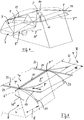
- Fig. 4 further basic setting options of the auxiliary linkage H are shown using a system similar to the pendulum arms 10 and 11.
- These pendulum arms are held on the support rods 4 such that they can pivot (arrow S, S ') in the area of the respective brackets 21 forming the connection point P.
- respective joint parts 22, 22 ' can be provided, so that a corresponding displacement L in the longitudinal direction is conceivable.
- a further embodiment of the holder is indicated by 21 ', towards the area of which a horizontal displacement (arrow N, N') of the parts of the auxiliary rod H is conceivable.
- the system according to Fig. 4 can be designed so that the bracket 22, 21 'the "first" Pendulum arm 9 (similar Fig. 2 ) detected and at the ends of the illustrated pendulum arms 10 and 11 with the brackets 21 defining the outer connection points form a "pendulum arm” chain that acts three times.
- auxiliary rods H can be completed during on-site assembly, the respective ends of the pendulum arms 16, 17 being inserted at the ends into the pockets 23 of the roof skin 7 '.
- the support rods 4, 6" or the respective Tensioning means can be used to pull a roof membrane 7 ′′ or the corresponding pendulum arms 16, 17 held in front tabs 25 into a respective position of use (arrow F, Fig. 8 ).
- Corresponding zip fastener connections are conceivable in the area of the seam zones 24, so that the auxiliary linkage H ′′ can be easily mounted in the manner of a canopy or the like.
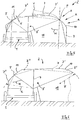
- Fig. 7 is similar to the canopy design according to Fig. 8 a fixing of the pendulum arms 12, 13, 14, 15 in the manner of an auxiliary linkage H 'is provided, this being connected on the one hand to the trailer 1 and on the other end in the cantilevered area engaging under a canopy 7'"which extends the roof skin 7
Landscapes
- Engineering & Computer Science (AREA)
- Architecture (AREA)
- Civil Engineering (AREA)
- Structural Engineering (AREA)
- Health & Medical Sciences (AREA)
- Public Health (AREA)
- Transportation (AREA)
- Mechanical Engineering (AREA)
- Tents Or Canopies (AREA)
Description
- Die Erfindung betrifft ein Zelt- oder Schutzdach in Form einer mit einem Campinganhänger o. dgl. Campingfahrzeugen transportablen Faltkonstruktion gemäß dem Oberbegriff des Anspruchs 1.
- Mit einem Campinganhänger transportable Faltkonstruktionen, die ein Zelt- oder Schutzdach bilden, sind seit längerem bekannt (
DE 28 41 550 ;US 7,178,536 B2 ), wobei mittels einer jeweiligen mit dem Anhänger verbundenen Gestängekonstruktion für eine flexible Dachhaut eine entsprechende Gebrauchslage vorgegeben wird. Die die Gestängekonstruktion bildenden Stützstangen sind dabei in Form von im wesentlichen verwindungssteifen Rohrteilen vorgesehen, die durch Gelenkteile o. dgl. Verbinder so gehalten sind, dass für derartige Faltsysteme durch eine entsprechende Stellbewegung unterschiedliche Gebrauchs- bzw. Nichtgebrauchsstellungen erreichbar sind. - In der Gebrauchslage der Gestängekonstruktion wird mittels der im wesentlichen geraden Stangen- und Rohrteile eine aus spezieller Zeltbahn bestehende Dachhaut zu pultförmigen, ebenen oder winklig zueinander verlaufenden Wandabschnitten geformt. Durch diesen Aufbau der Gestängekonstruktion nach Art eines Steilwandzeltes ist das System insgesamt windanfällig und der innere Nutzraum ist im Nahbereich der Stangen- und Rohrteile eingeengt. In
DE 39 08 603 A1 ist ein als einfaches Arbeitszelt für Versorgungsunternehmen verwendetes Giebelzelt vorgeschlagen, bei dem sich zwischen zwei Stützstangen eine jeweils endseitig mit diesem verbundene Quer-Stange erstreckt, die in Längsrichtung jeweilige Abknickungen bzw. eine bogenförmige Wölbung aufweist. Durch diese an beiden Enden mit Stützstangen zu verbindende bogenförmige Quer-Stange soll die Anwendbarkeit einfacher Zelte auf Baustellen von Versorgungsunternehmen verbessert werden. - Bei den am Markt befindlichen und als schwergewichtige Steilwand-Zeltdächer klassifizierbaren Gestängebaugruppen - in Abgrenzung zu leichtgewichtigen Kuppelzelten - werden neben geraden Stützstangen auch bereits "bogenförmige" Stützstangen verwendet, deren Anwendung sich jedoch nicht bewährt hat. Durch unterschiedliche Radien dieser Stützstangen weisen diese Systeme eine den Platzbedarf beim Transport erhöhende Sperrigkeit auf, eine gemeinsame Verpackung dieser Teile mit geraden Stangen ist hinderlich und bei der Montage einer Vielzahl von Stangen ist eine positionsgerechte Ausrichtung nur wenig bedienfreundlich möglich. Gemäß
DE 690 17 150 T2 ist ein Kuppelzelt in Leichtbauweise vorgeschlagen, bei dem an sich bekannte biegeelastische Stangen an beiden Enden bodenseitig fixiert werden. Dieses System muss durch zusätzliche längenverstellbare Zugglieder gegen Verformung im Bereich der bogenförmig aufgespannten Stangen geschützt werden. Bei einem Vorzelt für einen Wohnwagen gemäßDE 20 2006 013 697 U1 wird ein an einer Wand des Wohnwagens befestigtes Planenteil mit einem ebenfalls wandseitig zu fixierenden Gestänge kombiniert. Dieses zum Bodenbereich hin abgestützte Gestänge wirkt mit einem dieses kreuzenden Zusatzgestänge zusammen, so dass eine bogenförmige Ausrichtung des Planenteils erreicht wird und zwischen dem Wohnwagen und dem seitlichen Bodenbereich ein eine bogenförmige Seitenwand aufweisendes Vorzelt gebildet ist. In derUS 8,080,426 ist ein Campinganhänger mit einem Zelt offenbart, der zur Erweiterung der Zeltkontur schwenkbare Ausleger am Zeltgestänge vorsieht. DieDE 202 16 105 zeigt ein Gestänge für ein Zeltdach, mit dem ein über eine Zeltwand vorstehendes Vordach realisiert werden kann.US 5,449,032 zeigt ein Gestänge für ein bogenförmiges profiliertes Vordach einer Campingunterkunft. Hierbei sind die bogenförmig ausgebildeten Gestängeteile teleskopierbar. - Bei einem gattungsbildenden Campinganhänger in Form des zusammenklappbaren Wohnwagens gemäß
DE 692 08 053 T3 (ähnlichUS 7,178,536 B2 ) wird ein auch bei Steilwand-Zelten verwendetes Gerippe aus Rohr- und Profilteilen aufgebaut. Bei diesem Zeltaufbau ist zur Aufnahme einer biegsamen Platte als Abdeckteil auf dem Gerippe ein als Bogen-Stange geformtes Profilteil vorgesehen, das zur Aufnahme der Platte jeweilige Aussparungen und Halteteile aufweist. - Die Erfindung befasst sich mit dem Problem, ein insbesondere für einen Campinganhänger als transportable Faltkonstruktion vorgesehenes Zelt- oder Schutzdach zu schaffen, das in aufgestellter Gebrauchslage mit geringem technischem Aufwand einen Nutzraum aus weniger windanfälligen Gestängeteilen bildet, bei im wesentlichen gleich bleibenden Dachhautabmessungen einen verbesserten Komfort im Nutzraum aufweist und mit einer optisch ansprechenden Dachkontur formbare Erweiterungszonen ermöglicht.
- Die Erfindung löst diese Aufgabe durch ein Zelt- oder Schutzdach für einen Campinganhänger mit den Merkmalen des Anspruchs 1. Weitere vorteilhafte Ausgestaltungen ergeben sich aus den Ansprüchen 2 bis 14
- Bei einem insbesondere für Campinganhänger hergestellten Zelt- oder Schutzdach mit einer nach Art eines Steilwandzeltes auffaltbaren Grundstruktur ist erfindungsgemäß vorgesehen, dass dieses Faltsystem durch zumindest einen zusätzlichen, in die Gestängebaugruppe bzw. die von dieser gehaltene flexible Dachhaut integrierbaren Pendelarm ergänzt wird. Dieser Pendelarm wird nach Art eines Hilfsgestänges in das System integriert, so dass mit der weitgehend unveränderten Gestängebaugruppe - auch in der als schwergewichtig definierten Ausführung - bei geringem Aufwand jeweilige funktionale und optisch wirksame Erweiterungszonen am Zeltdach geschaffen werden.
- Das Konzept des Pendelarms basiert darauf, dass dieser an zumindest einem Gestängeteil einen Hauptverbindungspunkt definiert und von diesem aus jeweils zwei Arme als im wesentlichen frei abragende Teilbereiche unterhalb der Dachhaut wirksam sind, derart, dass das Arm-System entsprechend der Gestängebaugruppe um den Hauptverbindungspunkt "pendelnd" eingestellt werden kann bzw. unter Wirkung einer äußeren oder inneren Belastung eine "pendelnde" Ausgleichsbewegung ausführt.
- Mit dem erfindungsgemäßen Pendelarm wird eine einfache und im Anwendungsfall effiziente Lösung zur Funktionserweiterung an Campinganhänger-Zelten, Familienzelten, Wohnwagenvorzelten o. dgl. Konstruktionen vorgeschlagen. Bei der Anwendung des Hilfsgestänges mit Pendelarm kann ein bekanntes einfaches Zeltgestänge mit im wesentlichen geraden Stangen - die weiterhin eine schnelle Faltmontage beim Aufstellen bzw. eine Demontage durch Zurückfalten in den Bereich des Anhängers ermöglichen - mit den bekannten Vorteilen bei der Handhabung unverändert eingesetzt werden. Der erfindungsgemäße Pendelarm als ein in variablen Größen einsetzbares Zusatzbauteil kann so bemessen werden, dass in optisch hervortretenden Bereichen der Dachhaut eine unterschiedlichen Kundenwünschen entsprechende zusätzliche Bogenform erzeugt wird. Gleichzeitig kann damit die in den Abmessungen weitgehend unveränderte Dachhaut so verlagert werden, dass im darunter liegenden Nutzraum eine Volumen- bzw. Platzerweiterung erreicht wird und die Bequemlichkeit für den Nutzer verbessert ist.
- In vorteilhafter Ausführung werden ein oder mehrere Pendelarm(e) des Hilfsgestänges so in das Zeltgestänge integriert, dass eine verbesserte Aufnahme von Druck- und Zugbelastungen im Bereich der Dachhaut, beispielsweise durch Winddruck, Regenwasserauflage o. dgl. erreicht ist. Die bogenförmig in der Einbaulage gespannten Pendelarme schaffen dabei eine Konturform, die sich optimale an auftretende Windkräfte anpasst, so dass durch eine Wind ableitende Kontur das Systems insgesamt eine verbesserte Sturmfestigkeit aufweist und auch bei Starkregen eine optimale Wasserableitung gewährleistet ist.
- Die weitgehend beliebig erweiterbare Pendelarm-Struktur kann dabei so konzipiert werden, dass bisher üblicherweise angewandte Gestängeteile für Vorzelte, Sonnendächer o. dgl. durch die neuartigen Pendelarme ersetzt werden und so die Anzahl der Bauteile verringert wird. Die als Hilfsgestänge vorgesehenen Pendelarm-Teile können dabei auch in die als Rohrteile ausgebildeten Stützstangen eingebaut bzw. an diese angebaut werden, so dass diese als teleskopierbare Teile mitführbar und vor Ort in eine entsprechende Gebrauchsstellung herausziehbar sind. Ebenso ist vorgesehen, die Pendelarme als parallel zu den Gestängeteilen ausrichtbare Teile anzubringen, so dass eine enge Packlage in der Nichtgebrauch- bzw. Transportlage möglich wird.
- Bei derartigen Dachausführungen mit den Pendelarm-Teilen ist insbesondere eine Firststange des Faltgestänges in ihrem Einsatzbereich erweiterbar, wobei insbesondere die als biegsame Teile ausgebildeten Pendelarme längs bzw. quer zur Mittellängsachse positionierbar sind und damit eine Vielzahl von Funktionserweiterungen in diesem Dachbereich möglich ist.
- Weitere Einzelheiten und vorteilhafte Ausgestaltungen der Erfindung ergeben sich aus der nachfolgenden Beschreibung und der Zeichnung, die mehrere Ausführungsbeispiele eines Zelt- oder Schutzdaches mit erfindungsgemäßem Pendelarm veranschaulichen. In der Zeichnung zeigen:
- Fig. 1
- eine dem Stand der Technik entsprechende Ausführung des Campinganhängers mit aus diesem herausgeklappten Zelt- oder Schutzdach,
- Fig. 2
- eine Perspektivdarstellung ähnlich
Fig. 1 mit einer Gestängebaugruppe, in die ein erfindungsgemäßer Pendelarm integriert ist, - Fig. 3 und Fig. 4
- jeweilige Seitenansichten des Systems ähnlich
Fig. 2 mit mehreren Pendelarmen, - Fig. 5
- eine Seitenansicht ähnlich
Fig. 3 mit Erweiterung des Nutzraumes, - Fig. 6
- eine Prinzipdarstellung unterschiedlicher Befestigungs- und Bewegungsmöglichkeiten mehrerer der Pendelarme,
- Fig. 7
- eine Perspektivdarstellung ähnlich
Fig. 1 mit einer Grundausführung des Zeltes mit mehreren Pendelarmen, und - Fig. 8
- eine Prinzipdarstellung weiterer Einsatzmöglichkeiten von Pendelarmen im Bereich des Gestänges.
- In
Fig. 1 ist in einer Perspektivdarstellung eine Campingbaugruppe veranschaulicht, bei der ein eine transportable Faltkonstruktion aufnehmender Campinganhänger 1 verwendet wird. Aus diesem Campinganhänger 1 heraus wird ein insgesamt mit 2 bezeichnetes Zelt- oder Schutzdach aufgebaut, das nach Art einer Steilwand-Baugruppe 3 aufgestellt wird. Diese Konstruktion ist mit einer mehrere starre Stützstangen 4, 5, 6 aufweisenden und für eine flexible Dachhaut 7 die Gebrauchslage vorgebenden Gestängebaugruppe 8 versehen. - Ausgehend von dieser an sich bekannten Ausführung einer Zelt- oder Schutzdach-Konstruktion des Steilwandzeltes 2 ist erfindungsgemäß vorgesehen, diese Gestängebaugruppe 8 mit zumindest einem die Dachhaut 7' in Einbaulage profilierenden Pendelarm 9 zu versehen. Die Prinzipdarstellung gemäß
Fig. 2 verdeutlicht dabei, dass der einen Dachhautbereich 7' insbesondere bogenförmig profilierende Pendelarm 9 zur Gestängebaugruppe 8 hin einen als starre oder gelenkige Halterung ausführbaren Hauptverbindungspunkt P definiert, so dass eine durch Strichlinien verdeutlichte "Pendel-Beweglichkeit" des Systems erreicht wird und in diesem der Pendelarm 9 nach Art eines Hilfsgestänges H wirksam ist. - Es versteht sich, dass die Gestängebaugruppe 8 auch mit mehreren, jeweilige Bereiche der Dachhaut 7 untergreifenden Pendelarmen 10, 11 (
Fig. 3 bis 6 ), 12 bis 15 (Fig. 7 ) und/oder 16, 17 (Fig. 8 ) versehen sein kann. Bei 9' ist ein weiterer Pendelarm mit den Tragstangen der Gestängebaugruppe 8 verbunden (Fig. 2 ), wobei ein Verbindungspunkt P' definiert ist, der als "gleichwirkend" mit dem vorderen Punkt P anzusehen ist. - Bereits die Ausführung des Pendelarms 9 gemäß
Fig. 2 macht deutlich, dass mit dieser neuen Art des Hilfsgestänges H eine bogenförmige Dachhaut-Optik (Bogenlinie D, Strich-Punkt-Darstellung) erzeugbar ist. Ausgehend von diesem Steilwand-Konzept gemäßFig. 2 wird so mit geringem Aufwand erreicht, dass in den aus geraden Stützstangen 4, 6' resultierenden Dachbereichen eine zusätzliche Erweiterungskontur geschaffen werden kann. - Die Zusammenschau von
Fig. 2 undFig. 5 verdeutlicht, dass mittels der im jeweiligen Verbindungspunkt P, P' gelagerten Pendelarme 9, 9' bzw. 10 und 11 eine Spannstruktur gebildet ist, mittels der auf die jeweiligen bogenförmigen Bereiche der Dachhaut 7', 7" einwirkende Druck- und/oder Zugbelastungen durch Wind o. dgl. Witterungseinflüsse (Pfeil A) ausgleichbar sind. InFig. 2 undFig. 5 wird durch jeweilige Pfeile W eine aus diesen Belastungen resultierende Schwenkverlagerung im Bereich der Pendelarme 9, 10, 11 verdeutlicht, wobei deren Lage und die Position der Dachhaut 7 durch jeweilige Strichlinien angedeutet sind. Diese Prinzipdarstellungen zeigen auch, dass die Belastungen der Dachhaut 7 ausgehend vom Bereich der Pendelstangen 9, 9', 10, 11 gleichmäßig in die jeweilige Gestängebaugruppe 8 eingeleitet werden. Durch diese bogenförmigen Konturerweiterungen der Dachhaut 7', 7" ist gleichzeitig eine verbesserte Wasserableitung bei Starkregen oder Taubildung erreichbar. - Die Prinzipdarstellungen gemäß
Fig. 3 sowieFig. 5 und Fig. 6 verdeutlicht, dass mit den in variablen Abmessungen ausführbaren Pendelarmen 10, 11 jeweilige einen Zeltinnenraum 18 bogenförmig begrenzende und nach außen erweiterte Bereiche B, B', B" der Dachkonturen gebildet werden. Durch ein entsprechendes Konzept des Hilfsgestänges H mit Pendelarmen können damit für kundenspezifisch unterschiedliche Dachkonstruktionen jeweilige variable Volumen- bzw. Flächenerweiterungen im Bereich des inneren Nutzraumes 18 vorgegeben werden, so dass insgesamt eine Komfortverbesserung für derartige Campingzelte erreichbar ist. - Bei der konstruktiven Ausführung der vorbeschriebenen Hilfsgestänge H mit den Pendelarmen 9, 9', 10, 11, 12 bis 17 ist denkbar, die Pendelarme aus weitgehend biegestabilen und mit bogenförmigen Längskonturen geformten Bauteilen herzustellen (nicht dargestellt). Damit können zwar die vorgeschriebenen Effekte der bogenförmigen Konturerweiterung und der Belastungsverbesserung erreicht werden, gleichwohl sind diese biegestabilen Bauteile mit den Nachteilen komplizierter Handhabung und dem nachteilig großen Transportvolumen bekannter schwergewichtiger Zeltausführungen verbunden.
- Deshalb sieht das erfindungsgemäße Konzept Hilfsgestänge H, H', H" vor, bei denen die Pendelarme 9, 9', 10, 11, 12 bis 17 zumindest bereichsweise aus einem flexiblen Material bestehen und diese Pendelarme in der Einbaulage weitgehend variabel in eine vorgesehene Bogenkontur D, R umformbar sind. Sämtliche der Prinzipdarstellungen gemäß
Fig. 2 bis 8 gehen davon aus, dass die Pendelarme der Hilfsgestänge H, H', H" in der Einbaulage mittels jeweiliger - für derartige Faltkonstruktionen an sich bekannter - Spannelemente in die bogenförmige Dachkontur eingeformt werden. - Das Konzept des Hilfsgestänges H, H', H" sieht vor, dass die jeweiligen Pendelarme so in die Dachhaut 7 integriert sind, dass deren mit den an sich bekannten Halteteilen erzeugte Wandspannung auch zur Einstellung jeweiliger Radien R der Pendelarme 10, 11 (
Fig. 6 ,Fig. 8 ) nutzbar ist. In Anpassung an die jeweilige Ausführung des Zelt- oder Schutzdaches 2 können damit entsprechend der bogenförmigen Längskontur der Pendelarme 9, 9', 10, 11, 12 bis 17 gleichmäßige Radien R als Bogenform sichtbar sein, so dass der optische Gesamteindruck der Dach- und Wandteile der Zelte 2 insgesamt verbessert bzw. an die Vorgabe des Nutzers angepasst ist. - In
Fig. 2 ist eine Anwendung des einen Vorzeltbereich des Systems 2 bildenden Pendelarmes 9 gezeigt, wobei dieser in seiner Längsrichtung im wesentlichen mittig mit einer der vertikal verlaufenden Stützstangen 4' des Gestänges 8 verbunden ist und damit gleichzeitig den Hauptverbindungspunkt P als im wesentlichen mittig angeordnet definiert. Ebenso ist denkbar, dass der jeweilige Pendelarm ausgehend vom Hauptverbindungspunkt P die zwei Schenkelabschnitte 19, 20 als unterschiedlich lange Teile bildet (nicht dargestellt). - In
Fig. 4 sind weitere prinzipielle Einstellmöglichkeiten des Hilfsgestänges H anhand eines Systems ähnlich der Pendelarme 10 und 11 dargestellt. Diese Pendelarme sind im Bereich jeweiliger den Verbindungspunkt P bildender Halterungen 21 schwenkbar (Pfeil S, S') an den Stützstangen 4 gehalten. Im Bereich dieser Halterungen 21 können jeweilige Gelenkteile 22, 22' vorgesehen sein, so dass eine entsprechende Verschiebung L in Längsrichtung denkbar ist. Mit 21' ist eine weitere Ausführung der Halterung angedeutet, zu deren Bereich hin eine horizontale Verschiebung (Pfeil N, N') der Teile des Hilfsgestänges H denkbar ist. Das System gemäßFig. 4 kann dabei so ausgeführt sein, dass die Halterung 22, 21' den "ersten" Pendelarm 9 (ähnlichFig. 2 ) erfasst und an dessen Enden die dargestellten Pendelarme 10 und 11 mit den die äußeren Verbindungspunkte definierenden Halterungen 21 eine damit dreifach wirkende "Pendelarm"-Kette bilden. - In der Ausführungsform des Hilfsgestänges H' mit den Pendelarmen 16, 17 gemäß
Fig. 8 ist eine weitere Festlegungsvariante der Pendelarme 16, 17 im Bereich der Dachhaut 7 dargestellt, wobei ausgehend von den Hauptverbindungspunkten P' die jeweilige Auskraglänge K der Pendelarme 16, 17 einstellbar sein kann. - Für eine unmittelbare Festlegung der Pendelarme 16, 17 an der Dachhaut 7 sind entsprechende als Aufnahmetaschen bzw. Aufnahmelaschen geformte Bereiche 23 vorgesehen. Denkbar ist, diese durch jeweilige Saumzonen 24 abzutrennen und im Innenraum dieser Ausnehmungen 23 die Pendelarme 16, 17 zu fixieren. Dieses Systems des Hilfsgestänges H" kann bei der vor Ort erfolgenden Montage komplettiert werden, wobei die jeweiligen Enden der Pendelarme 16, 17 endseitig in die Taschen 23 der Dachhaut 7' eingesteckt werden. Entsprechend der Konstruktion der Stützstangen 4, 6" bzw. der jeweiligen nicht näher dargestellten Spannmittel kann ein Dachhautbereit 7" bzw. die entsprechend in vorderen Laschen 25 gehaltenen Pendelarmen 16, 17 in eine jeweilige Gebrauchslage gezogen werden (Pfeil F,
Fig. 8 ). Im Bereich der Saumzonen 24 sind entsprechende Reißverschlussverbindungen denkbar, so dass das Hilfsgestänge H" nach Art eines Vordaches o. dgl. einfach montierbar ist. - In
Fig. 7 ist ähnlich der Vordach-Ausführung gemäßFig. 8 eine Festlegung der Pendelarme 12, 13, 14, 15 nach Art eines Hilfsgestänges H' vorgesehen, wobei dieses einerseits mit dem Anhänger 1 verbunden ist und anderenends im freitragenden Bereich ein die Dachhaut 7 erweiterndes Vordach 7'" untergreift. Ebenso ist denkbar, diese viergliedrige Pendelarm-Konstruktion gemäß H' für ein mehrere Dachhaut-Lagen aufweisendes Doppel-Dach-Gestänge vorzusehen, so dass insbesondere eine obere der Dachhautlagen (z.B. 7'") ebenfalls in einer bogenförmigen Kontur ausrichtbar ist (ähnlichFig. 7 ).
Claims (14)
- Zelt- oder Schutzdach, welches eine mit einem Campinganhänger (1) transportable Faltkonstruktion ist, mit einer Gestängebaugruppe (8) als Steilwand-Baugruppe (3) und einer flexiblen Dachhaut (7), wobei die Gestängebaugruppe (8) starre Stützstangen (4, 5, 6) aufweist und die Gebrauchslage für die flexible Dachhaut (7) vorgibt dadurch gekennzeichnet, dass ein Pendelarm (9, 9'; 10, 11; 12 bis 15; 16, 17) die Dachhaut (7') zumindest bereichsweise erfassend und an zumindest einem Gestängeteil der Gestängebaugruppe (8, 8', 8") einen Hauptverbindungspunkt (P, P') definierend ausgebildet ist, wobei von dem Hauptverbindungspunkt (P, P')aus zwei Arme des Pendelarms (9, 9'; 10, 11; 12 bis 15; 16, 17) als im wesentlichen frei abragende Teilbereiche unterhalb der Dachhaut wirksam sind.
- Zelt- oder Schutzdach nach Anspruch 1, dadurch gekennzeichnet, dass der Pendelarm (9) in seiner Längsrichtung im wesentlichen mittig mit einer der vertikal verlaufenden Stützstangen (4') des Gestänges (8) verbunden ist und damit der Hauptverbindungspunkt (P) definiert ist.
- Zelt- oder Schutzdach nach Anspruch 1, dadurch gekennzeichnet, dass der Pendelarm (9) ausgehend vom Hauptverbindungspunkt (P, P') zwei unterschiedlich lange Schenkelabschnitte (19, 20) definiert.
- Zelt- oder Schutzdach nach einem der Ansprüche 1 bis 3, dadurch gekennzeichnet, dass der Pendelarm (10, 11; 16, 17) im Bereich des Gestänges (8, 8') und/oder der Dachhaut (7) verschiebbar gehalten ist, derart, dass ausgehend vom Hauptverbindungspunkt (P, P')unterschiedliche Längen (L, K) des Pendelarms (10, 11; 16,17) einstellbar sind.
- Zelt- oder Schutzdach nach einem der Ansprüche 1 bis 4, dadurch gekennzeichnet, dass der Pendelarm (9, 9'; 10, 11; 12 bis 15; 16, 17) die Dachhaut (7') zumindest bereichsweise bogenförmig profiliert.
- Zelt- oder Schutzdach nach einem der Ansprüche 1 bis 5, dadurch gekennzeichnet, dass mittels des zumindest einen als variables Zusatzbauteil vorgesehenen und nach Art eines Hilfsgestänges (H, H', H") wirksamen Pendelarms (9, 9'; 10, 11; 12 bis 15; 16, 17) ausgehend vom jeweiligen Hauptverbindungspunkt (P, P') eine bogenförmige Dachhaut-Optik (D) erzeugbar ist, derart, dass zusätzlich zu den aus geraden Stützstangen (4, 5, 6) resultierenden Dachbereichen (7) der Steilwand-Baugruppe (3) diese mit einer Erweiterungskontur (B, B', B") versehen ist.
- Zelt- oder Schutzdach nach Anspruch 6, dadurch gekennzeichnet, dass der bzw. die Pendelarme des Hilfsgestänges (H, H', H") aus weitgehend biegestabilen und zumindest bereichsweise mit einer bogenförmigen Längskontur vorgeformten Bauteilen bestehen.
- Zelt- oder Schutzdach nach Anspruch 6, dadurch gekennzeichnet, dass der bzw. die Pendelarme (9, 9'; 10, 11; 12 bis 15; 16, 17) des Hilfsgestänges (H, H', H") aus einem flexiblen Material bestehen und damit diese Pendelarme mittels jeweiliger für Faltkonstruktionen an sich bekannter Spannelemente in der Einbaulage die bogenförmige Dachkontur (D) bilden.
- Zelt- oder Schutzdach nach Anspruch 8, dadurch gekennzeichnet, der bzw. die Pendelarme (9, 9'; 10, 11; 12 bis 15; 16, 17) in der Einbaulage weitgehend variabel in eine vorgesehene Bogenkontur (D, R) umformbar sind.
- Zelt- oder Schutzdach nach einem der Ansprüche 1 bis 9, dadurch gekennzeichnet, dass die Gestängebaugruppe (8, 8', 8") mit mehreren jeweilige Bereiche der Dachhaut (7', 7") untergreifenden Pendelarmen (9, 9'; 10, 11; 12 bis 15; 16, 17) versehen ist.
- Zelt- oder Schutzdach nach einem der Ansprüche 1 bis 10, dadurch gekennzeichnet, dass die Abmessungen der Pendelarme (10, 11) variabel ausgebildet sind, und mit den Pendelarmen (10,11) jeweilige vom Zeltinnenraum (18) bogenförmig nach außen erweiterte Dachkonturen gebildet und damit variable Volumen- bzw. Flächenerweiterungen (B, B', B") im Bereich des inneren Nutzraumes vorgebbar sind.
- Zelt- oder Schutzdach nach einem der Ansprüche 1 bis 11, dadurch gekennzeichnet, dass der Pendelarm (16, 17) unmittelbar an der Dachhaut (7) in einer Aufnahmetasche, -lasche o. dgl. Bereich (23) verschieblich gehalten ist.
- Zelt- oder Schutzdach nach einem der Ansprüche 1 bis 12, dadurch gekennzeichnet, dass eine den Pendelarm (16, 17) umgrenzende Saumzone (24) mit einem Reißverschluss vorgesehen ist.
- Zelt- oder Schutzdach nach einem der Ansprüche 1 bis 13, dadurch gekennzeichnet, dass der zumindest eine Pendelarm (12, 13, 14, 15) in die Konstruktion eines zwei Dachhaut-Lagen (7) aufweisenden Doppel-Dach-Gestänges integrierbar ist.
Priority Applications (1)
| Application Number | Priority Date | Filing Date | Title |
|---|---|---|---|
| PL09011076T PL2159352T3 (pl) | 2008-09-01 | 2009-08-28 | Dach namiotu lub dach ochronny |
Applications Claiming Priority (1)
| Application Number | Priority Date | Filing Date | Title |
|---|---|---|---|
| DE102008045274A DE102008045274A1 (de) | 2008-09-01 | 2008-09-01 | Zelt- oder Schutzdach als Teil eines Campinganhängers |
Publications (3)
| Publication Number | Publication Date |
|---|---|
| EP2159352A2 EP2159352A2 (de) | 2010-03-03 |
| EP2159352A3 EP2159352A3 (de) | 2017-04-19 |
| EP2159352B1 true EP2159352B1 (de) | 2020-09-30 |
Family
ID=41360189
Family Applications (1)
| Application Number | Title | Priority Date | Filing Date |
|---|---|---|---|
| EP09011076.8A Active EP2159352B1 (de) | 2008-09-01 | 2009-08-28 | Zelt- oder Schutzdach |
Country Status (4)
| Country | Link |
|---|---|
| EP (1) | EP2159352B1 (de) |
| DE (1) | DE102008045274A1 (de) |
| DK (1) | DK2159352T3 (de) |
| PL (1) | PL2159352T3 (de) |
Cited By (1)
| Publication number | Priority date | Publication date | Assignee | Title |
|---|---|---|---|---|
| WO2024093046A1 (zh) * | 2022-11-01 | 2024-05-10 | 秋野地(厦门)户外装备科技有限公司 | 一种全覆盖车边帐 |
Families Citing this family (1)
| Publication number | Priority date | Publication date | Assignee | Title |
|---|---|---|---|---|
| DE202016005067U1 (de) | 2016-08-17 | 2016-09-07 | Wolfgang Schütz | Wagen, insbesondere ein Anhänger, mit Campingaufsatz |
Family Cites Families (10)
| Publication number | Priority date | Publication date | Assignee | Title |
|---|---|---|---|---|
| NL167636C (nl) | 1977-09-29 | 1982-01-18 | Egbert Berend Holtkamp | Kampeervouwwagen. |
| DE3908603A1 (de) * | 1989-03-16 | 1990-09-20 | Maschinen & Geraete Gmbh | Giebelzelt |
| GB2237827B (en) * | 1989-11-11 | 1993-10-06 | Aarn Tate | Improvements in or relating to tents |
| US5080426A (en) * | 1990-03-30 | 1992-01-14 | Johnson Frank L | Collapsible camper tent trailer |
| NL9101928A (nl) * | 1991-11-19 | 1993-06-16 | Egbert Berend Holtkamp | Opvouwbare caravan. |
| US5449032A (en) * | 1994-04-19 | 1995-09-12 | Blevins; Timothy D. | Awning bow |
| NL1021062C2 (nl) * | 2002-07-12 | 2004-01-13 | Egbert Berend Holtkamp | Voortentconstructie en kampeerverblijf voorzien van een voortentconstructie. |
| DE20216105U1 (de) * | 2002-10-16 | 2003-01-02 | Herzog GmbH & Co KG, 74366 Kirchheim | Vorrichtung für ein Dachteil |
| DE202006013697U1 (de) * | 2006-08-25 | 2007-09-20 | Herzog Gmbh & Co. Kg | Vorzelt für Wohnwagen |
| DK2169147T3 (en) * | 2008-09-24 | 2018-12-17 | Egbert Berend Holtkamp | Tent Construction |
-
2008
- 2008-09-01 DE DE102008045274A patent/DE102008045274A1/de not_active Withdrawn
-
2009
- 2009-08-28 DK DK09011076.8T patent/DK2159352T3/da active
- 2009-08-28 EP EP09011076.8A patent/EP2159352B1/de active Active
- 2009-08-28 PL PL09011076T patent/PL2159352T3/pl unknown
Non-Patent Citations (1)
| Title |
|---|
| None * |
Cited By (1)
| Publication number | Priority date | Publication date | Assignee | Title |
|---|---|---|---|---|
| WO2024093046A1 (zh) * | 2022-11-01 | 2024-05-10 | 秋野地(厦门)户外装备科技有限公司 | 一种全覆盖车边帐 |
Also Published As
| Publication number | Publication date |
|---|---|
| EP2159352A2 (de) | 2010-03-03 |
| DE102008045274A1 (de) | 2010-03-04 |
| DK2159352T3 (da) | 2020-12-21 |
| EP2159352A3 (de) | 2017-04-19 |
| PL2159352T3 (pl) | 2021-03-08 |
Similar Documents
| Publication | Publication Date | Title |
|---|---|---|
| DE102009020795A1 (de) | Sonnenschutz | |
| EP2159352B1 (de) | Zelt- oder Schutzdach | |
| EP2169147B1 (de) | Zeltkonstruktion | |
| DE102011054205A1 (de) | Zelt | |
| DE20016555U1 (de) | Vorzelt mit aufblasbarem Gerüst | |
| EP3372754B1 (de) | Vorzelt für ein fahrzeug, insbesondere für einen wohnwagen oder ein wohnmobil | |
| DE60300978T2 (de) | Tragbare Struktur | |
| DE19940599A1 (de) | Witterungsschutz zur außenseitigen Anordnung bei einer stationären Unterkunft, insbesondere einem Wohnfahrzeug | |
| DE102016109234B4 (de) | Adapterstück mit verschiebbaren Kupplungselementen und Überdachungssystem | |
| DE102013003460A1 (de) | Zusatzdachvorrichtung zur Anordnung an einer Kraftfahrzeugkarosserie | |
| EP2256269B1 (de) | Zeltdach für ein Campingfahrzeug | |
| DE202011109766U1 (de) | Vorrichtung zum Ausformen einer gewölbten aufrollbaren Bedachung | |
| DE10218906B4 (de) | Überdachung für Sitzgarnituren | |
| EP3748099B1 (de) | Markise | |
| DE29709641U1 (de) | Schutzdach für Wohnmobile und Wohnwagen | |
| EP2443957A1 (de) | Schirmsystem mit trichterförmiger Membran | |
| DE102007037729B4 (de) | Rohreinheit mit zwei Leitungsrohre verbindendem Schellenorgan | |
| DE102006051617B4 (de) | Vorzelt für einen Campingwagen | |
| AT256544B (de) | Wetterschutz-Überdachung für Gartenbeete od. dgl. | |
| DE20106237U1 (de) | Schutzdach | |
| EP0867322B1 (de) | Schutzdach für Wohnmobile und Wohnwagen | |
| DE20216105U1 (de) | Vorrichtung für ein Dachteil | |
| AT241288B (de) | Zeltgarage für Kraftfahrzeuge | |
| DE2904112A1 (de) | Wohnwagen | |
| DE2748242A1 (de) | Dachkonstruktion, bestehend aus starrem rahmengestaenge, das von einem folienmaterial ueberdeckt ist, fuer eine baracke o.dgl. |
Legal Events
| Date | Code | Title | Description |
|---|---|---|---|
| PUAI | Public reference made under article 153(3) epc to a published international application that has entered the european phase |
Free format text: ORIGINAL CODE: 0009012 |
|
| AK | Designated contracting states |
Kind code of ref document: A2 Designated state(s): AT BE BG CH CY CZ DE DK EE ES FI FR GB GR HR HU IE IS IT LI LT LU LV MC MK MT NL NO PL PT RO SE SI SK SM TR |
|
| AX | Request for extension of the european patent |
Extension state: AL BA RS |
|
| PUAL | Search report despatched |
Free format text: ORIGINAL CODE: 0009013 |
|
| AK | Designated contracting states |
Kind code of ref document: A3 Designated state(s): AT BE BG CH CY CZ DE DK EE ES FI FR GB GR HR HU IE IS IT LI LT LU LV MC MK MT NL NO PL PT RO SE SI SK SM TR |
|
| AX | Request for extension of the european patent |
Extension state: AL BA RS |
|
| RIC1 | Information provided on ipc code assigned before grant |
Ipc: B60P 3/34 20060101ALI20170311BHEP Ipc: E04H 15/08 20060101AFI20170311BHEP |
|
| STAA | Information on the status of an ep patent application or granted ep patent |
Free format text: STATUS: REQUEST FOR EXAMINATION WAS MADE |
|
| 17P | Request for examination filed |
Effective date: 20170615 |
|
| RBV | Designated contracting states (corrected) |
Designated state(s): AT BE BG CH CY CZ DE DK EE ES FI FR GB GR HR HU IE IS IT LI LT LU LV MC MK MT NL NO PL PT RO SE SI SK SM TR |
|
| STAA | Information on the status of an ep patent application or granted ep patent |
Free format text: STATUS: EXAMINATION IS IN PROGRESS |
|
| 17Q | First examination report despatched |
Effective date: 20180809 |
|
| GRAP | Despatch of communication of intention to grant a patent |
Free format text: ORIGINAL CODE: EPIDOSNIGR1 |
|
| STAA | Information on the status of an ep patent application or granted ep patent |
Free format text: STATUS: GRANT OF PATENT IS INTENDED |
|
| INTG | Intention to grant announced |
Effective date: 20200330 |
|
| GRAS | Grant fee paid |
Free format text: ORIGINAL CODE: EPIDOSNIGR3 |
|
| GRAA | (expected) grant |
Free format text: ORIGINAL CODE: 0009210 |
|
| STAA | Information on the status of an ep patent application or granted ep patent |
Free format text: STATUS: THE PATENT HAS BEEN GRANTED |
|
| AK | Designated contracting states |
Kind code of ref document: B1 Designated state(s): AT BE BG CH CY CZ DE DK EE ES FI FR GB GR HR HU IE IS IT LI LT LU LV MC MK MT NL NO PL PT RO SE SI SK SM TR |
|
| REG | Reference to a national code |
Ref country code: GB Ref legal event code: FG4D Free format text: NOT ENGLISH Ref country code: CH Ref legal event code: EP |
|
| REG | Reference to a national code |
Ref country code: AT Ref legal event code: REF Ref document number: 1318943 Country of ref document: AT Kind code of ref document: T Effective date: 20201015 Ref country code: DE Ref legal event code: R096 Ref document number: 502009016278 Country of ref document: DE |
|
| REG | Reference to a national code |
Ref country code: IE Ref legal event code: FG4D Free format text: LANGUAGE OF EP DOCUMENT: GERMAN |
|
| REG | Reference to a national code |
Ref country code: DK Ref legal event code: T3 Effective date: 20201218 |
|
| REG | Reference to a national code |
Ref country code: NL Ref legal event code: FP |
|
| PG25 | Lapsed in a contracting state [announced via postgrant information from national office to epo] |
Ref country code: BG Free format text: LAPSE BECAUSE OF FAILURE TO SUBMIT A TRANSLATION OF THE DESCRIPTION OR TO PAY THE FEE WITHIN THE PRESCRIBED TIME-LIMIT Effective date: 20201230 Ref country code: GR Free format text: LAPSE BECAUSE OF FAILURE TO SUBMIT A TRANSLATION OF THE DESCRIPTION OR TO PAY THE FEE WITHIN THE PRESCRIBED TIME-LIMIT Effective date: 20201231 Ref country code: NO Free format text: LAPSE BECAUSE OF FAILURE TO SUBMIT A TRANSLATION OF THE DESCRIPTION OR TO PAY THE FEE WITHIN THE PRESCRIBED TIME-LIMIT Effective date: 20201230 Ref country code: FI Free format text: LAPSE BECAUSE OF FAILURE TO SUBMIT A TRANSLATION OF THE DESCRIPTION OR TO PAY THE FEE WITHIN THE PRESCRIBED TIME-LIMIT Effective date: 20200930 Ref country code: HR Free format text: LAPSE BECAUSE OF FAILURE TO SUBMIT A TRANSLATION OF THE DESCRIPTION OR TO PAY THE FEE WITHIN THE PRESCRIBED TIME-LIMIT Effective date: 20200930 Ref country code: SE Free format text: LAPSE BECAUSE OF FAILURE TO SUBMIT A TRANSLATION OF THE DESCRIPTION OR TO PAY THE FEE WITHIN THE PRESCRIBED TIME-LIMIT Effective date: 20200930 |
|
| PG25 | Lapsed in a contracting state [announced via postgrant information from national office to epo] |
Ref country code: LV Free format text: LAPSE BECAUSE OF FAILURE TO SUBMIT A TRANSLATION OF THE DESCRIPTION OR TO PAY THE FEE WITHIN THE PRESCRIBED TIME-LIMIT Effective date: 20200930 |
|
| REG | Reference to a national code |
Ref country code: LT Ref legal event code: MG4D |
|
| PG25 | Lapsed in a contracting state [announced via postgrant information from national office to epo] |
Ref country code: CZ Free format text: LAPSE BECAUSE OF FAILURE TO SUBMIT A TRANSLATION OF THE DESCRIPTION OR TO PAY THE FEE WITHIN THE PRESCRIBED TIME-LIMIT Effective date: 20200930 Ref country code: EE Free format text: LAPSE BECAUSE OF FAILURE TO SUBMIT A TRANSLATION OF THE DESCRIPTION OR TO PAY THE FEE WITHIN THE PRESCRIBED TIME-LIMIT Effective date: 20200930 Ref country code: SM Free format text: LAPSE BECAUSE OF FAILURE TO SUBMIT A TRANSLATION OF THE DESCRIPTION OR TO PAY THE FEE WITHIN THE PRESCRIBED TIME-LIMIT Effective date: 20200930 Ref country code: RO Free format text: LAPSE BECAUSE OF FAILURE TO SUBMIT A TRANSLATION OF THE DESCRIPTION OR TO PAY THE FEE WITHIN THE PRESCRIBED TIME-LIMIT Effective date: 20200930 Ref country code: LT Free format text: LAPSE BECAUSE OF FAILURE TO SUBMIT A TRANSLATION OF THE DESCRIPTION OR TO PAY THE FEE WITHIN THE PRESCRIBED TIME-LIMIT Effective date: 20200930 Ref country code: PT Free format text: LAPSE BECAUSE OF FAILURE TO SUBMIT A TRANSLATION OF THE DESCRIPTION OR TO PAY THE FEE WITHIN THE PRESCRIBED TIME-LIMIT Effective date: 20210201 |
|
| PG25 | Lapsed in a contracting state [announced via postgrant information from national office to epo] |
Ref country code: ES Free format text: LAPSE BECAUSE OF FAILURE TO SUBMIT A TRANSLATION OF THE DESCRIPTION OR TO PAY THE FEE WITHIN THE PRESCRIBED TIME-LIMIT Effective date: 20200930 Ref country code: IS Free format text: LAPSE BECAUSE OF FAILURE TO SUBMIT A TRANSLATION OF THE DESCRIPTION OR TO PAY THE FEE WITHIN THE PRESCRIBED TIME-LIMIT Effective date: 20210130 |
|
| PG25 | Lapsed in a contracting state [announced via postgrant information from national office to epo] |
Ref country code: SK Free format text: LAPSE BECAUSE OF FAILURE TO SUBMIT A TRANSLATION OF THE DESCRIPTION OR TO PAY THE FEE WITHIN THE PRESCRIBED TIME-LIMIT Effective date: 20200930 |
|
| REG | Reference to a national code |
Ref country code: DE Ref legal event code: R097 Ref document number: 502009016278 Country of ref document: DE |
|
| PLBE | No opposition filed within time limit |
Free format text: ORIGINAL CODE: 0009261 |
|
| STAA | Information on the status of an ep patent application or granted ep patent |
Free format text: STATUS: NO OPPOSITION FILED WITHIN TIME LIMIT |
|
| 26N | No opposition filed |
Effective date: 20210701 |
|
| PG25 | Lapsed in a contracting state [announced via postgrant information from national office to epo] |
Ref country code: IT Free format text: LAPSE BECAUSE OF FAILURE TO SUBMIT A TRANSLATION OF THE DESCRIPTION OR TO PAY THE FEE WITHIN THE PRESCRIBED TIME-LIMIT Effective date: 20200930 |
|
| PG25 | Lapsed in a contracting state [announced via postgrant information from national office to epo] |
Ref country code: SI Free format text: LAPSE BECAUSE OF FAILURE TO SUBMIT A TRANSLATION OF THE DESCRIPTION OR TO PAY THE FEE WITHIN THE PRESCRIBED TIME-LIMIT Effective date: 20200930 |
|
| REG | Reference to a national code |
Ref country code: CH Ref legal event code: PL |
|
| PG25 | Lapsed in a contracting state [announced via postgrant information from national office to epo] |
Ref country code: MC Free format text: LAPSE BECAUSE OF FAILURE TO SUBMIT A TRANSLATION OF THE DESCRIPTION OR TO PAY THE FEE WITHIN THE PRESCRIBED TIME-LIMIT Effective date: 20200930 |
|
| REG | Reference to a national code |
Ref country code: BE Ref legal event code: MM Effective date: 20210831 |
|
| PG25 | Lapsed in a contracting state [announced via postgrant information from national office to epo] |
Ref country code: LI Free format text: LAPSE BECAUSE OF NON-PAYMENT OF DUE FEES Effective date: 20210831 Ref country code: CH Free format text: LAPSE BECAUSE OF NON-PAYMENT OF DUE FEES Effective date: 20210831 |
|
| PG25 | Lapsed in a contracting state [announced via postgrant information from national office to epo] |
Ref country code: IS Free format text: LAPSE BECAUSE OF FAILURE TO SUBMIT A TRANSLATION OF THE DESCRIPTION OR TO PAY THE FEE WITHIN THE PRESCRIBED TIME-LIMIT Effective date: 20210130 Ref country code: LU Free format text: LAPSE BECAUSE OF NON-PAYMENT OF DUE FEES Effective date: 20210828 |
|
| PG25 | Lapsed in a contracting state [announced via postgrant information from national office to epo] |
Ref country code: IE Free format text: LAPSE BECAUSE OF NON-PAYMENT OF DUE FEES Effective date: 20210828 Ref country code: BE Free format text: LAPSE BECAUSE OF NON-PAYMENT OF DUE FEES Effective date: 20210831 |
|
| REG | Reference to a national code |
Ref country code: AT Ref legal event code: MM01 Ref document number: 1318943 Country of ref document: AT Kind code of ref document: T Effective date: 20210828 |
|
| PG25 | Lapsed in a contracting state [announced via postgrant information from national office to epo] |
Ref country code: AT Free format text: LAPSE BECAUSE OF NON-PAYMENT OF DUE FEES Effective date: 20210828 |
|
| PG25 | Lapsed in a contracting state [announced via postgrant information from national office to epo] |
Ref country code: HU Free format text: LAPSE BECAUSE OF FAILURE TO SUBMIT A TRANSLATION OF THE DESCRIPTION OR TO PAY THE FEE WITHIN THE PRESCRIBED TIME-LIMIT; INVALID AB INITIO Effective date: 20090828 Ref country code: CY Free format text: LAPSE BECAUSE OF FAILURE TO SUBMIT A TRANSLATION OF THE DESCRIPTION OR TO PAY THE FEE WITHIN THE PRESCRIBED TIME-LIMIT Effective date: 20200930 |
|
| PG25 | Lapsed in a contracting state [announced via postgrant information from national office to epo] |
Ref country code: MK Free format text: LAPSE BECAUSE OF FAILURE TO SUBMIT A TRANSLATION OF THE DESCRIPTION OR TO PAY THE FEE WITHIN THE PRESCRIBED TIME-LIMIT Effective date: 20200930 |
|
| PG25 | Lapsed in a contracting state [announced via postgrant information from national office to epo] |
Ref country code: MT Free format text: LAPSE BECAUSE OF FAILURE TO SUBMIT A TRANSLATION OF THE DESCRIPTION OR TO PAY THE FEE WITHIN THE PRESCRIBED TIME-LIMIT Effective date: 20200930 |
|
| PGFP | Annual fee paid to national office [announced via postgrant information from national office to epo] |
Ref country code: NL Payment date: 20250821 Year of fee payment: 17 |
|
| PGFP | Annual fee paid to national office [announced via postgrant information from national office to epo] |
Ref country code: DK Payment date: 20250821 Year of fee payment: 17 Ref country code: DE Payment date: 20250625 Year of fee payment: 17 |
|
| PGFP | Annual fee paid to national office [announced via postgrant information from national office to epo] |
Ref country code: PL Payment date: 20250814 Year of fee payment: 17 |
|
| PGFP | Annual fee paid to national office [announced via postgrant information from national office to epo] |
Ref country code: GB Payment date: 20250822 Year of fee payment: 17 |
|
| PGFP | Annual fee paid to national office [announced via postgrant information from national office to epo] |
Ref country code: FR Payment date: 20250821 Year of fee payment: 17 |
|
| PG25 | Lapsed in a contracting state [announced via postgrant information from national office to epo] |
Ref country code: TR Free format text: LAPSE BECAUSE OF FAILURE TO SUBMIT A TRANSLATION OF THE DESCRIPTION OR TO PAY THE FEE WITHIN THE PRESCRIBED TIME-LIMIT Effective date: 20200930 |