EP2153751B1 - Verbindungsvorrichtung - Google Patents
Verbindungsvorrichtung Download PDFInfo
- Publication number
- EP2153751B1 EP2153751B1 EP08751927A EP08751927A EP2153751B1 EP 2153751 B1 EP2153751 B1 EP 2153751B1 EP 08751927 A EP08751927 A EP 08751927A EP 08751927 A EP08751927 A EP 08751927A EP 2153751 B1 EP2153751 B1 EP 2153751B1
- Authority
- EP
- European Patent Office
- Prior art keywords
- connecting elements
- portions
- axially
- external gear
- outer circumferential
- Prior art date
- Legal status (The legal status is an assumption and is not a legal conclusion. Google has not performed a legal analysis and makes no representation as to the accuracy of the status listed.)
- Not-in-force
Links
Images


Classifications
-
- B—PERFORMING OPERATIONS; TRANSPORTING
- B60—VEHICLES IN GENERAL
- B60N—SEATS SPECIALLY ADAPTED FOR VEHICLES; VEHICLE PASSENGER ACCOMMODATION NOT OTHERWISE PROVIDED FOR
- B60N2/00—Seats specially adapted for vehicles; Arrangement or mounting of seats in vehicles
- B60N2/02—Seats specially adapted for vehicles; Arrangement or mounting of seats in vehicles the seat or part thereof being movable, e.g. adjustable
- B60N2/22—Seats specially adapted for vehicles; Arrangement or mounting of seats in vehicles the seat or part thereof being movable, e.g. adjustable the back-rest being adjustable
- B60N2/235—Seats specially adapted for vehicles; Arrangement or mounting of seats in vehicles the seat or part thereof being movable, e.g. adjustable the back-rest being adjustable by gear-pawl type mechanisms
- B60N2/2356—Seats specially adapted for vehicles; Arrangement or mounting of seats in vehicles the seat or part thereof being movable, e.g. adjustable the back-rest being adjustable by gear-pawl type mechanisms with internal pawls
- B60N2/236—Seats specially adapted for vehicles; Arrangement or mounting of seats in vehicles the seat or part thereof being movable, e.g. adjustable the back-rest being adjustable by gear-pawl type mechanisms with internal pawls linearly movable
-
- B—PERFORMING OPERATIONS; TRANSPORTING
- B60—VEHICLES IN GENERAL
- B60N—SEATS SPECIALLY ADAPTED FOR VEHICLES; VEHICLE PASSENGER ACCOMMODATION NOT OTHERWISE PROVIDED FOR
- B60N2/00—Seats specially adapted for vehicles; Arrangement or mounting of seats in vehicles
- B60N2/02—Seats specially adapted for vehicles; Arrangement or mounting of seats in vehicles the seat or part thereof being movable, e.g. adjustable
- B60N2/22—Seats specially adapted for vehicles; Arrangement or mounting of seats in vehicles the seat or part thereof being movable, e.g. adjustable the back-rest being adjustable
- B60N2/225—Seats specially adapted for vehicles; Arrangement or mounting of seats in vehicles the seat or part thereof being movable, e.g. adjustable the back-rest being adjustable by cycloidal or planetary mechanisms
- B60N2/2252—Seats specially adapted for vehicles; Arrangement or mounting of seats in vehicles the seat or part thereof being movable, e.g. adjustable the back-rest being adjustable by cycloidal or planetary mechanisms in which the central axis of the gearing lies inside the periphery of an orbital gear, e.g. one gear without sun gear
-
- B—PERFORMING OPERATIONS; TRANSPORTING
- B60—VEHICLES IN GENERAL
- B60N—SEATS SPECIALLY ADAPTED FOR VEHICLES; VEHICLE PASSENGER ACCOMMODATION NOT OTHERWISE PROVIDED FOR
- B60N2/00—Seats specially adapted for vehicles; Arrangement or mounting of seats in vehicles
- B60N2/02—Seats specially adapted for vehicles; Arrangement or mounting of seats in vehicles the seat or part thereof being movable, e.g. adjustable
- B60N2/22—Seats specially adapted for vehicles; Arrangement or mounting of seats in vehicles the seat or part thereof being movable, e.g. adjustable the back-rest being adjustable
- B60N2/225—Seats specially adapted for vehicles; Arrangement or mounting of seats in vehicles the seat or part thereof being movable, e.g. adjustable the back-rest being adjustable by cycloidal or planetary mechanisms
- B60N2/2254—Seats specially adapted for vehicles; Arrangement or mounting of seats in vehicles the seat or part thereof being movable, e.g. adjustable the back-rest being adjustable by cycloidal or planetary mechanisms provided with braking systems
-
- Y—GENERAL TAGGING OF NEW TECHNOLOGICAL DEVELOPMENTS; GENERAL TAGGING OF CROSS-SECTIONAL TECHNOLOGIES SPANNING OVER SEVERAL SECTIONS OF THE IPC; TECHNICAL SUBJECTS COVERED BY FORMER USPC CROSS-REFERENCE ART COLLECTIONS [XRACs] AND DIGESTS
- Y10—TECHNICAL SUBJECTS COVERED BY FORMER USPC
- Y10T—TECHNICAL SUBJECTS COVERED BY FORMER US CLASSIFICATION
- Y10T403/00—Joints and connections
- Y10T403/32—Articulated members
- Y10T403/32254—Lockable at fixed position
- Y10T403/32262—At selected angle
- Y10T403/32418—Plural distinct positions
Definitions
- the present invention relates to connection devices. More particularly, the present invention relates to connection devices for relatively rotatably connecting two subject components.
- a seat back is rotatably connected to a seat cushion via a reclining device, so that a tilt angle of the seat back can be adjusted.
- a reclining device is taught by JP 2006-14942 A .
- the reclining device described therein includes a disk-shaped ratchet affixed to a frame portion of the seat back and a disk-shaped guide affixed to a frame portion of the seat cushion. The ratchet and the guide are axially assembled while being mutually supported, so as to rotate relative to each other.
- the ratchet and the guide are circumferentially connected by a cylindrical retainer member along outer circumferential portions thereof, so as to not be axially disengaged from each other.
- the retainer member has a flange-shaped retainer portion.
- the retainer portion is formed in one end periphery of the cylindrical retainer member and is shaped to be capable of being axially held against an outer disk surface of the ratchet. Therefore, the ratchet and the guide can be axially positioned in the cylindrical retainer member by the retainer portion in order to be incorporated thereinto.
- the ratchet and the guide are disposed in the retainer member. Thereafter, the other end periphery of the retainer member is bent and crimped. As a result, the bent end periphery of the retainer member is axially held against an inner disk surface of the guide, so that the ratchet and the guide can be axially clamped.
- the guide has radially depressed recesses that are formed in the outer circumferential portion thereof at intervals.
- the retainer member has retainer strips formed therein. The retainer strips are axially inserted into the recesses, so that the outer circumferential portion of the guide can be guided by the retainer strips.
- a cylindrical portion of the retainer member is constructed of a plurality of retainer strips that are circumferentially formed therein at intervals: Further, the retainer strips are inserted into the recesses of the guide, so as to guide the same. Therefore, the retainer member can be prevented from being excessively radially projected from the outer circumferential portion of the guide.
- the reclining device can be radially downsized.
- the bent end periphery of the retainer member can be radially inwardly extended along the guide while being positioned closely adjacent to each other. Therefore, projected dowels that are used to attach the guide to the frame portion of the seat back cannot substantially be formed in positions closer to an outer circumferential periphery of the guide.
- a connection device in accordance with the preamble of claim 1 is known from EP 1676742 A1 .
- the present invention has the object to ensure a connection strength between a connection device and subject components even when the connecting device is downsized.
- the connecting device includes two connecting elements and a retainer member.
- the two connecting elements are respectively integrally connected to one or the other of the two subject components and are coupled to each other so as to be rotatable relative to each other.
- the retainer member is capable of preventing the two connecting elements, from being axially separated from each other.
- the two connecting elements are capable of being switched between a relatively rotatable condition and a relatively unrotatable condition depending on an operational condition of a rotation prevention mechanism disposed therebetween.
- the retainer member has a plurality of axially extending retainer strips that are capable of axially crossing over and confining outer circumferential portions of the connecting elements.
- One of the connecting elements has radially inwardly depressed portions that are respectively formed circumferentially in plural locations on the outer circumferential portion thereof.
- the retainer member is constructed such that when the retainer strips are axially inserted into the depressed portions formed in the outer circumferential portion of one of the connecting elements and then insertion distal ends of the support strips are radially inwardly bent to form contact surface portions, the contact surface portions can be axially held against the outer circumferential portion of one of the connecting elements.
- One of the connecting elements has axially projected fitting portions that are capable of being fitted to one of the subject components, and the fitting portions are formed close to an outer circumferential periphery of one of the connecting elements and circumferentially in locations positioned between the depressed portions.
- the axially extending retainer strips of the retainer member are axially inserted into the depressed portions formed in the outer circumferential portion of one of the connecting elements and then are bent, so that the bent formed contact surface portions thereof can be axially held against one of the connecting elements.
- the retainer member can prevent one of the connecting elements from being- disengaged
- the connecting device can be downsized.
- the fitting portions formed in one of the connecting elements are formed circumferentially in the locations positioned between the depressed portions, the fitting portions cannot interfere with the above-described bent ends (the contact surface portions) of the retainer member. As a result, the fitting portions can be positioned closer to an outer circumferential periphery of one of the connecting elements. Therefore, even when the connecting device is downsized, a connection strengths between one of the connecting elements and one of the subject components can be ensured.
- one of the connecting elements is formed to have a diameter greater than the diameter of the other of the connecting elements and has an outwardly-faced toothed surface that is capable of meshing with an inwardly-faced toothed surface that is formed in the other of the connecting elements.
- the projected fitting portions formed in one of the connecting elements are formed in radially outside positions of the outwardly-faced toothed surface.
- the fitting portions are positioned outside of the outwardly-faced toothed surface formed in one of the connecting elements, the fitting portions are positioned closer to the outer circumferential periphery. Therefore, the connection strength between one of the connecting elements and one of the subject components via the fitting portions can be increased.
- the present invention can be constructed as follows. That is, the projected fitting portions formed in one of the connecting elements are shaped to be extended in a circumferential direction.
- the fitting portions formed in one of the connecting elements are shaped to be extended in the circumferential direction, the fitting portions have increased shear strength in the circumferential direction. Further, the fitting portions and one of the subject components can be fitted to each other in a large area. As a result, the connection strength between one of the connecting elements and one of the subject components can be increased.
- the present invention can be constructed as follows. That is, one of the connecting elements has an axially projected external gear wheel having outwardly-faced teeth that are formed in an outer circumferential surface thereof.
- the other of the connecting elements has an internal gear wheel having inwardly-faced teeth that are formed in an inner circumferential surface thereof and are capable of meshing with the outwardly-faced teeth of the external gear wheel.
- a pusher member is disposed between the connecting elements. The pusher member functions to press the external gear wheel to the internal gear wheel so as to mesh with each other. Upon circumferential rotation of the pusher member, the external gear wheel is rotationally pressed so as to rotate relative to the internal gear wheel while changing a meshing position therebetween.
- the connecting device is implemented as a device in which the external gear wheel formed in one of the connecting elements meshes with the internal gear wheel formed in the other of the connecting elements and in which both of the gear wheels can rotate relative to each other while changing the meshing position therebetween.
- the present invention can be constructed as follows. That is, the connecting device is constructed as a reclining device that is capable of rotatably connecting a seat back of a vehicle seat to a fixed body such as a seat cushion such that a tilting angle of the seat back can be adjusted.
- the connecting device is constructed as the reclining device that is capable of connecting the seat back to the fixed body such as the seat cushion such that the tilting angle of the seat back can be adjusted. Therefore, the reclining device can be compactly arranged with the increased connecting strength.
- FIG. 3 schematically shows a structure of a vehicle seat 1 having reclining devices 4 that correspond to connecting devices of the present invention.
- a seat back 2 is connected to a seat cushion 3 via a pair of reclining devices 4 that are disposed on both side lower portions of the seat back 2.
- Each of the reclining devices 4 is normally maintained in a condition in which a tilting angle of the seat back 2 is fixed. However, each of the reclining devices 4 is constructed to adjust the tilting angle of the seat back 2 when operating shafts 4c and 4c inserted thereinto are rotated.
- the operating shafts 4c are integrally connected to each other via a connection rod 4r, so as to be synchronously rotated when an electric motor (not shown) connected to one of the operating shafts 4c is actuated.
- the electric motor (not shown) is constructed to be turned on and off and to be switched between normal and reverse rotational modes by operating a switch that is attached to, for example, a side portion of the vehicle seat 1.
- the reclining devices 4 When the reclining devices 4 are positioned in conditions in which the operating shafts 4c are not rotated, the reclining devices 4 are maintained in conditions in which the tilting angle of the seat back 2 is fixed to a desired angle.
- the operating shafts 4c are rotationally moved by actuation of the electric motor, the reclining devices 4 are switched in conjunction with the motion, so as to change the tilting angle of the seat back 2.
- the reclining devices 4 have the substantially same construction as each other with the exception of one aspect that they are symmetrically formed. Therefore, the reclining device 4 that is disposed on the right side in FIG. 3 will be described hereinafter.
- the reclining device 4 includes a disk-shaped internal gear member 10, a disk-shaped external gear member 20, a pair of piece-shaped pusher members 30A and 30B, an open ring-shaped spring member 40, a cylindrical operating member 50, a rod-like operating shaft 4c, and a thin cylindrical retainer member 70, which are assembled as a unit. Further, these components are axially set in order after the internal gear member 10 is first introduced into the retainer member 70, so as to be assembled as a unit ( FIG. 4 ).
- the external gear member 20 corresponds to one of connecting elements of the present invention.
- the internal gear member 10 corresponds to the other of the connecting elements of the present invention. Structures of the components described above will be described in detail with reference to FIGS. 1 and 2 hereinafter.
- the disk-shaped internal gear member 10 is shaped by half die cutting the same in a thickness direction (an axial direction), so that an outer circumferential peripheral portion thereof can be cylindrically projected.
- the cylindrically projected portion includes inwardly-faced teeth 11a that are formed in an inner circumferential surface thereof. That is, the cylindrically projected portion is formed as an internal gear wheel 11.
- the internal gear member 10 has a cylindrical portion 12 formed in a central portion thereof. The cylindrical portion 12 is projected in the same direction as the internal gear wheel 11.
- the cylindrical portion 12 has an axis that is aligned with an axis 11r of the internal gear member 10 (the internal gear wheel 11).
- the cylindrical portion 12 has a circular shaft insertion bore 12a that is formed therethrough.
- An outer disk surface of the internal gear member 10 is joined to a plate surface of a back frame 2f of the seat back 2, so that the internal gear member 10 is integrally affixed to the back frame 2f.
- the internal gear member 10 has three oval-shaped dowels 13 ⁇ that are respectively formed in a disk-shaped portion thereof so as to be projected from the outer disk surface thereof. (Symbol “ ⁇ " means plural number.)
- the dowels 13 ⁇ are formed in positions closer to an outer circumferential periphery of the disk-shaped portion so as to be circumferentially positioned at equal intervals.
- the back frame 2f has dowel insertion holes 2a that are formed therethrough.
- the dowel insertion holes 2a are shaped such that the dowels 13 ⁇ can be fitted thereinto. Therefore, the internal gear member 10 is securely integrally attached to the back frame 2f by fitting the dowels 13 ⁇ to the dowel insertion holes 2a formed in the back frame 2f and then welding fitted portions.
- each of the dowels 13 ⁇ is shaped to be extended in a circumferential direction. Therefore, each of the dowels 13 ⁇ has increased shear strength in the circumferential direction.
- the dowels 13 ⁇ can be fitted to the back frame 2f in a large area.
- the internal gear member 10 can be rigidly integrally attached to the back frame 2f via the dowels 13 ⁇ .
- the back frame 2f has a circular shaft insertion bore 2c that is formed therethrough in a thickness direction.
- the shaft insertion bore 2c is shaped to have the same diameter as the shaft insertion bore 12a formed in the internal gear member 10.
- the shaft insertion bores 12a and 2c are shaped such that the rod-like operating shaft 4c can be inserted thereinto, which will be described hereinafter.
- the external gear member 20 is formed as a disk-shaped member having a diameter greater than the diameter of the internal gear member 10.
- the external gear member 20 is shaped by half die cutting the same in a thickness direction (an axial direction), so that a disk-shaped central portion thereof can be cylindrically projected.
- the cylindrically projected portion includes outwardly-faced teeth 21a that are formed in an outer circumferential surface thereof.
- the cylindrically projected portion is formed as an external gear wheel 21.
- the external gear wheel 21 has a diameter smaller than the diameter of the internal gear wheel 11 formed in the internal gear member 10.
- the external gear member 20 when the external gear member 20 thus constructed is axially coupled to the internal gear member 10 while the external gear wheel 21 meshes with the internal gear wheel 11, the external gear member 20 and the internal gear member 10 can be assembled, so as to be rotated relative to each other while meshing with each other.
- the external gear member 20 has an enlarged opening 22 having a diameter greater than the shaft insertion bore 12a formed in the central portion of the internal gear member 10 described above.
- the enlarged opening 22 is formed in the central portion of the external gear member 20.
- the enlarged opening 22 has an axis that is aligned with an axis 21r of the external gear member 20 (the external gear wheel 21).
- the external gear member 20 is coupled to the internal gear member 10 while the cylindrical portion 12 formed in the internal gear member 10 is positioned within the enlarged opening 22. Further, the external gear member 20 is coupled to the internal gear member 10 while the axes 21r and 11r thereof are offset from each other. Further, the external gear wheel 21 is constructed to have teeth number fewer than the teeth number of the internal gear wheel 11. In particular, the teeth number of the teeth 21a of the external gear wheel 21 is thirty three whereas the teeth number of the teeth 11a of the internal gear wheel 11 is thirty four.
- the internal gear member 10 is connected to the back frame 2f.
- the external gear member 20 is connected to the cushion frame 3f, which will be described hereinafter. Therefore, actually, the internal gear member 10 can rotate relative to the external gear member 20 while changing the meshing position therebetween. As a result, when rotational motion between the external gear wheel 21 and the internal gear wheel 11 is performed described above, as shown in FIG 3 , the tilting angle of the seat back 2 can be adjusted.
- the external gear member 20 has four oval-shaped dowels 23 ⁇ that are respectively formed in a disk-shaped portion thereof so as to be projected from an outer disk surface thereof.
- the dowels 23 ⁇ correspond to fitting portions of the present invention.
- the dowels 23 ⁇ are formed in radially outside positions of the external gear wheel 21 and are positioned closer to an outer circumferential periphery of the disk-shaped portion.
- the dowels 23 ⁇ are formed in locations in which projected portions 20y ⁇ are formed.
- the projected portions 20y ⁇ are formed circumferentially in locations positioned between radially inwardly depressed portions 20x ⁇ that are formed circumferentially in four locations on an outer circumferential portion of the external gear member 20.
- the depressed portions 20x ⁇ and the projected portions 20y ⁇ that are formed in the outer circumferential portion of the external gear member 20 are respectively positioned circumferentially in four locations on the outer circumferential portion of the external gear member 20 at equal intervals, so as to be circumferentially alternated with each other.
- the dowels 23 ⁇ described above are formed in the locations in which projected portions 20y ⁇ are formed. As a result, the dowels 23 ⁇ can be positioned circumferentially in four locations at equal intervals.
- the cushion frame 3f has dowel insertion holes 3a ⁇ that are formed therethrough.
- the dowel insertion holes 3a ⁇ are shaped such that the dowels 23 ⁇ can be fitted thereto. Therefore, the external gear member 20 is securely integrally attached to the cushion frame 3f by fitting the dowels 23 ⁇ to the dowel insertion holes 3a ⁇ formed in the cushion frame 3 f and then welding fitted portions.
- each of the dowels 23 ⁇ is shaped to be extended in a circumferential direction. Therefore, each of the dowels 23 ⁇ has increased shear strength in the circumferential direction.
- the dowels 23 ⁇ can be fitted to the cushion frame 3f in a large area.
- the external gear member 20 can be rigidly attached to the cushion frame 3f via the dowels 23 ⁇ .
- the cushion frame 3f has a circular enlarged opening 3c that is formed therethrough in a thickness direction.
- the enlarged opening 3c is shaped to have the same diameter as the enlarged opening 22 formed in the external gear member 20 described above.
- the enlarged openings 22 and 3c are shaped such that the rod-like operating shaft 4c can be inserted thereinto, which will be described hereinafter.
- the pusher members 30A and 30B are formed as arcuate piece-shaped members that are symmetrically curved.
- the pusher members 30A and 30B are assembled while they are received in the enlarged opening 22 formed in the external gear member 20 described above.
- the pusher members 30A and 30B are disposed in an eccentric space that is formed between an inner circumferential surface of the enlarged opening 22 and an outer circumferential surface of the cylindrical portion 12 of the internal gear member 10 described above.
- the pusher members 30A and 30B are respectively arcuately tapered so as to be oppositely introduced into a narrowing space portion formed between the enlarged opening 22 of the external gear member 20 and the cylindrical portion 12 of the internal gear member 10 (a narrowing space portion positioned in a lower side in FIG 5 ).
- engagement end portions 41A and 41B of the open ring-shaped spring member 40 is attached to the pusher members 30A and 30B while straddling the same. Therefore, the pusher members 30A and 30B are constantly biased by a biasing force of the spring member 40, so as to be maintained in a condition in which tapered lower end portions thereof are oppositely introduced into the above-described narrowing space portion.
- the external gear member 20 can normally be maintained in a condition in which it is upwardly biased with respect to the cylindrical portion 12 by the pusher members 30A and 30B, so that the external gear wheel 21 is pressed to the internal gear wheel 11 while meshing with each other without producing clearance (backrush) therebetween.
- the external gear member 20 can be maintained in a condition (an unrotatable condition) in which the revolving motion previously described is prevented relative to the internal gear member 10.
- the unrotatable condition due to biasing of the pusher members 30A and 30B can be released by rotating the operating shaft 4c.
- the cylindrical operating member 50 is axially attached and secured to the operating shaft 4c so as to be integrally rotated therewith.
- a serrated portion (not shown) is axially formed in an outer circumferential surface of the operating shaft 4c.
- the operating member 50 connected to the operating shaft 4c has an arm portion 52 that is axially projected from a lower end portion of a collar portion formed in an end periphery thereof in the same axial direction as the cylindrical portion 51.
- the arm portion 52 is constructed so as to be fitted to the space that is positioned between the lower end portions of the pusher members 30A and 30B.
- FIG 6 when the operating member 50 is rotated, for example, clockwise in the drawings, a bottom surface portion of the left pusher member 30A can be pressed upwardly, so that the left pusher member 30A can be rotated clockwise along the inner circumferential surface of the enlarged opening 22.
- the pusher member 30A Upon rotational movement of the pusher member 30A, the inner circumferential surface of the enlarged opening 22 is pressed, so that the external gear wheel 21 can rotate clockwise along the toothed inner circumferential surface of the internal gear wheel 11 while changing the meshing position therebetween.
- the right pusher member 30B can be rotationally moved clockwise due to the biasing force of the spring member 40 while it is introduced into the space portion that is widened due to the movement described above.
- the seat back 2 can be rotated in a forward or backward tilting direction. Further, as shown in FIG 5 , when rotational operation of the operating shaft 4c is stopped, the pusher members 30A and 30B are placed again in the condition in which they are introduced into the narrowing space portion by the biasing force of the spring member 40, so that the reclining device 4 can be returned to the condition in which it is prevented from rotating.
- the retainer member 70 is formed by stamping a thin steel sheet so as to have a ring shape. Further, the retainer member 70 is cylindrically shaped by axially half die cutting the same and has a flange-shaped support wall 71. The support wall 71 is formed in a right back side end of the retainer member 70 and has an axial surface. Further, an axially extending cylindrical portion of the retainer member 70 is constructed of four axially extending arcuate retainer strips 73 ⁇ that are circumferentially plurally formed at intervals, so as to have a discontinuous cylindrical shape as a whole.
- the retainer strips 73 ⁇ are circumferentially disposed at equal intervals and are constructed to be axially inserted into the depressed portions 20x ⁇ formed in the outer circumferential portion of the external gear member 20. Therefore, the internal gear member 10 is first inserted into the cylindrical portion of the retainer member 70 constructed as described above, so as to be introduced thereinto in a condition in which the outer circumferential portion of the internal gear member 10 is axially held against the support wall 71 described above.
- the external gear member 20 is axially inserted into the cylindrical portion of the retainer member 70 while the retainer strips 73 ⁇ of the retainer member 70 are axially inserted into the depressed portions 20x ⁇ formed in the outer circumferential portion of the external gear member 20.
- the projected portions 20y ⁇ are axially inserted into removed portions 73a ⁇ that are formed between the retainer strips 73 ⁇ of the retainer member 70.
- the external gear member 20 is incorporated into the cylindrical portion of the retainer member 70.
- the axially extending retainer strips 73 ⁇ of the retainer member 70 are axially inserted into the depressed portions 20x ⁇ formed in the outer circumferential portion of the external gear member 20 and then are bent, so that the bent formed contact surface portions 73b ⁇ thereof can be axially held against the external gear member 20.
- the retainer member 70 can prevent the external gear member 20 from being disengaged.
- the reclining device 4 can be downsized.
- the dowels 23 ⁇ formed in the external gear member 20 are formed circumferentially in the locations positioned between the depressed portions 20x ⁇ (the locations in which the projected portions 20y ⁇ are formed), the dowels 23 ⁇ cannot interfere with the above-described contact surface portions 73b ⁇ that are formed in the retainer member 70 by bending. As a result, the dowels 23 ⁇ can be positioned closer to the outer circumferential periphery of the external gear member 20. Therefore, even when the reclining device 4 is downsized, a connection strength between the external gear member 20 and the cushion frame 3f (a subject component) can be ensured.
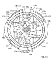
- the reclining device 104 includes a disk-shaped ratchet 110, a disk-shaped guide 120, a pair of pawls 130 that are vertically disposed between disk surfaces of the ratchet 110 and the guide 120, a slide cam 140 that is disposed between the disk surfaces of the ratchet 110 and the guide 120, a hinge cam 150 that is capable of sliding the slide cam 140, a biasing spring 160 that is capable of rotatably biasing the hinge cam 150, and a retainer member 170 that is capable of fastening the ratchet 110 and the guide 120 so as to not be prevented from being axially separated from each other, which are assembled as a unit.
- the guide 120 corresponds to one of connecting elements of the present invention.
- the ratchet 110 corresponds to the other of the connecting elements of the present invention.
- the above-described ratchet 110 is constructed such that an outer disk surface thereof can be integrally connected to the back frame 2f ( FIG. 1 ) of the seat back 2.
- the guide 120 is constructed such that an outer disk surface thereof can be integrally connected to the cushion frame 3f ( FIG. 1 ) of the seat cushion 3.
- the ratchet 110 has a disk-shaped portion 111 and a cylindrical portion 112.
- the cylindrical portion 112 is projected from a circumferential periphery of the disk-shaped portion 111 in a thickness direction.
- the cylindrical portion 112 includes inwardly-faced toothed portions 112a and projected surface portions 112b that are formed in an inner circumferential surface thereof.
- the projected surface portions 112b are formed as flattened surfaces that are protruded radially inwardly than the inwardly-faced toothed portions 112a. Further, the projected surface portions 112b are axisymmetrically formed in two locations of the inner circumferential surface of the cylindrical portion 112.
- circumferential angular ranges corresponding to the toothed portions 112a can be defined as an lockable rotational region in which the reclining device 104 can be locked due to engagement of the toothed portions 112a and the pawls 130, which will be described hereinafter.
- circumferential angular ranges corresponding to the projected surface portions 112b can be defined as a free rotational region in which the reclining device 104 cannot be locked.
- the ratchet 110 has a plurality of cylindrical dowels 113a ⁇ and a D-shaped dowel 113b that are respectively formed in the disk-shaped portion 111 thereof so as to be projected from the outer disk surface thereof.
- the dowels 113a ⁇ and the D-shaped dowel 113b are formed as fitting portions that can securely integrally bond the ratchet 110 to the back frame 2f ( FIG. 1 ) described above.
- the ratchet 110 has a through hole 114 that is formed in a central portion of the disk-shaped portion 111 thereof.
- the through hole 114 is shaped such that an operating shaft (not shown) for locking and unlocking the reclining device 104 can be inserted therethrough.
- the guide 120 is formed as a disk-shaped member having a diameter greater than the diameter of the ratchet 110.
- the guide 120 has a disk-shaped portion 121 and a cylindrical portion 122.
- the cylindrical portion 122 is projected from a circumferential periphery of the disk-shaped portion 121 toward the ratchet 110 in a thickness direction.
- the cylindrical portion 122 is shaped to surround an outer circumferential periphery of the cylindrical portion 112 of the ratchet 110 described above.
- the guide 120 and the ratchet 110 can slidably rotate relative to each other while the cylindrical portions 112 and 122 are fitted to each other.
- the guide 120 has a plurality of cylindrical dowels 124a ⁇ and a D-shaped dowel 124b that are respectively formed in the disk-shaped portion 121 thereof so as to be projected from the outer disk surface thereof.
- the dowels 124a ⁇ and the D-shaped dowel 124b are formed as fitting portions (which correspond to the fitting portions of the present invention) that can securely integrally bond the guide 120 to the cushion frame 3f ( FIG. 1 ) described above.
- the guide 120 has a through hole 125 that is formed in a central portion of the disk-shaped portion 121 thereof.
- the through hole 114 is shaped such that the operating shaft (not shown) can be inserted therethrough.
- the guide 120 has depressed portions 120x ⁇ into which retainer strips 173 ⁇ of the retainer member 170 can be axially inserted, and projected portions 120y ⁇ that are capable of being axially inserted into removed portions 173a ⁇ and being held against engagement surface portions 172 ⁇ .
- the depressed portions 120x ⁇ and the projected portions 120y ⁇ are respectively formed in an outer circumferential portion of the guide 120 and are respectively positioned circumferentially in four locations on the outer circumferential portion at equal intervals, so as to be circumferentially alternated with each other.
- the guide 120 has a cross-shaped guide groove 123 that is formed in the disk-shaped portion 121 thereof by depressing an inner disk surface thereof in the thickness direction.
- upper and lower groove portions thereof are respectively formed as pawl grooves 123a that are capable of receiving the pawls 130 therein.
- the pawl grooves 123a are defined by guide walls 121a and 121b and guide walls 121 c and 121d that can function as right and left walls, and are capable of guiding the pawls 130 so as to slide the same radially inwardly and outwardly of the guide 120 (upwardly and downwardly in the drawings) only therealong. Further, in the guide groove 123, right and left groove portions thereof and a central groove portion positioned therebetween are formed as a laterally continuous slide cam groove 123b that is capable of receiving the slide cam 140 therein.
- the slide cam groove 123b is defined by the guide walls 121a and 121c and the guide walls 121b and 121d that can function as upper and lower walls, and is capable of guiding the slide cam 140 so as to slide the same radially inwardly and outwardly of the guide 120 (rightwardly and leftwardly in the drawings) only therealong.
- the guide 120 has pin-shaped spring engagement portions 126 that are respectively formed in the disk-shaped portion 121 thereof so as to be projected from the outer disk surface thereof.
- the spring engagement portions 126 are respectively formed as functional elements to which an outer end 162 of the biasing spring 160 (a coil spring) is attached, which will be described hereinbefore. Further, the spring engagement portions 126 are positioned in circumferentially two locations, so that an attaching position of the outer end 162 of the biasing spring 160 can be changed.
- the pawls 130 are formed as piece-shaped members that are received in the pawl grooves 123a formed in the guide 120.
- the pawls 130 are formed vertically symmetrically with each other.
- an outer circumferential periphery of each of the pawls 130 is shaped to an arcuate shape so as to correspond to the inner circumferential surface of the cylindrical portion 112 of the ratchet 110.
- the pawls 130 have outwardly-faced toothed portions 130a that are formed in an arcuately curved outer circumferential surface thereof and are capable of meshing with the inwardly-faced toothed portions 112a formed in the inner circumferential surface of the cylindrical portion 112 of the ratchet 110.
- the outwardly-faced toothed portions 130a can mesh with the inwardly-faced toothed portions 112a formed in the inner circumferential surface of the ratchet 110.
- the pawls 130 and the ratchet 110 can be circumferentially integrated with each other.
- the pawls 130 can only slide radially inwardly and outwardly with respect to the guide 120.
- the ratchet 110 can be prevented from relatively rotating with respect to the guide 120 via the pawls 130 meshing therewith.
- the reclining device 104 can be positioned in a locking condition. The locking condition of the reclining device 104 can be released when the pawls 130 are retracted radially inwardly and are disengaged from the ratchet 110.
- the pawls 130 can be slid radially inwardly and outwardly when the slide cam 140 disposed between the pawls 130 is moved.
- the slide cam 140 is formed as a piece-shaped members that is capable being received in the slide cam groove 123b formed in the guide 120 described above.
- the slide cam 140 is vertically symmetrically shaped.
- the slide cam 140 has shoulder portions 142 that are capable of pushing the pawls 130 radially outwardly, and hooks 144 that are capable of pulling the pawls 130 radially inwardly. Further, the shoulder portions 142 and the hooks 144 are respectively formed in upper and lower peripheries of the slide cam 140.
- the pawls 130 previously described are respectively formed as gate-shaped members in which radially inner sides thereof are partially removed.
- the pawls 130 respectively have gatepost-shaped leg portions 132.
- the pawls 130 can be pressed radially outwardly by the slide cam 140 when the leg portions 132 contact an upper peripheral surface portion and a lower peripheral surface portion of the slide cam 140.
- the leg portions 132 can be positioned on the shoulder portions 142 of the slide cam 140, so that the pawls 130 can be maintained in a condition in which they are pushed radially outwardly.
- the pawls 130 are maintained in a condition in which the outwardly-faced toothed portions 130a mesh with the inwardly-faced toothed portions 112a of the ratchet 110. Further, when the slide cam 140 is slid rightwardly, the hooks 144 of the slide cam 140 are hooked on engagement portions 131 formed in gate-shaped inside surfaces of the pawls 130 so that the pawls 130 can be pulled radially inwardly. As a result, the leg portions 132 of the pawls 130 positioned on the shoulder portions 142 are introduced into recessed portions 143 that are positioned left sides thereof, so that the pawls 130 can be disengaged from the ratchet 110.
- the slide cam 140 described above can be slid rightwardly and leftwardly in the drawings when the hinge cam 150 is moved.
- the hinge cam 150 is disposed in a cam hole 141 that is formed through a central portion of the slide cam 140.
- the hinge cam 150 is rotatably positioned in the cam hole 141 that is formed through the central portion of the slide cam 140.
- the binge cam 150 is constantly rotationally biased counterclockwise in the drawings by a biasing force of the biasing spring 160 (the coil spring) that is attached between the hinge cam 150 and the guide 120.
- An inner end 161 of the biasing spring 160 is connected to an spring engagement portion 151.
- the outer end 162 of the biasing spring 160 is connected to the spring engagement portion 126 of the guide 120.
- the hinge cam 150 can normally press the slide cam 140 from an inner surface side of the cam hole 141 by a projection 152 formed in an outer circumferential portion of the hinge cam 150, so as to slide the slide cam 140 leftwardly in the drawings.
- the leg portions 132 can be positioned on the shoulder portions 142 of the slide cam 140, so that the pawls 130 can be maintained in a locked condition in which the pawls 130 engage the ratchet 110.
- the hinge cam 150 is integrally connected to the operating shaft (not shown) previously described. Therefore, when the operating shaft is rotated via an operation lever (not shown), the hinge cam 150 can be rotated clockwise against the biasing force of the biasing spring 160 described above. As a result, the slide cam 140 can be slid rightwardly in the drawings, so that the pawls 130 can be disengaged from the ratchet 110.
- the retainer member 170 Similar to the retainer member 70 in Embodiment 1, the retainer member 170 is cylindrically shaped and has a flange-shaped support wall 171, four retainer strips 173 ⁇ and engagement surface portions 172 ⁇ .
- the support wall 171 is formed in a right back side end of the retainer member 170 and has an axial surface.
- the retainer strips 173 ⁇ are axially extended and are capable of being axially inserted into the depressed portions 120x ⁇ of the guide 120 described above.
- the engagement surface portions 172 ⁇ are capable of axially receiving the projected portions 120y ⁇ of the guide 120.
- the ratchet 110 and the guide 120 are inserted into a cylindrical portion of the retainer member 170, distal ends of the retainer strips 173 ⁇ that are inserted into the depressed portions 120x ⁇ are bent. Thereafter, contact surface portions 173b ⁇ formed by bending the retainer strips 173 ⁇ are crimped against the outer disk surface of the guide 120.
- the guide 120 and the ratchet 110 are coupled to each other via the retainer member 170, so as to be prevented from being axially separated from each other.
- the support wall 171 described above has a plurality of projections 171a ⁇ that are formed therein so as to project in a thickness direction (an axial direction) thereof.
- the projections 171a are circumferentially positioned at equal intervals. Therefore, the support wall 171 can contact the outer disk surface of the ratchet 110 via point contact of the projections 171a ⁇ . As a result, the ratchet 110 can be smoothly rotated.
- the connecting device of the present invention is applied to the reclining device 4 that connects the seat back 2 to the seat cushion 3 (a fixed body) such that the tilting angle of the seat back can be adjusted.
- the connecting device can be applied to a device that is capable of connecting the seat back 2 to a vehicle floor (the fixed body) such that the tilting angle thereof can be adjusted.
- the connecting device can be applied to a device that is capable of rotatably connecting the vehicle seat to the vehicle floor. Further, the connecting device can be applied to a device that is capable of tiltably connecting an ottoman supporting leg regions of a sitting person to the seat cushion 3 or the vehicle floor.
- one of the connecting elements (the external gear member 20 or the guide 120) and the other of the connecting elements (the internal gear member 10 or the ratchet 110) are mutually supportively coupled so as to be rotated relative to each other.
- the connecting elements can be coupled using a supporting member so as to be rotated relative to each other.
- one of the connecting elements has the depressed portions that are evenly formed circumferentially in four locations on the outer circumferential portion thereof.
- the depressed portions can be unevenly formed.
- the number of the depressed portions is not limited.
- the internal gear member 10 in Embodiment 1 and the ratchet 110 in Embodiment 2 can be constructed as one of connecting elements having the depressed portions that are capable of axially receiving the retainer strips of the retainer member.
Landscapes
- Engineering & Computer Science (AREA)
- Aviation & Aerospace Engineering (AREA)
- Transportation (AREA)
- Mechanical Engineering (AREA)
- Chairs For Special Purposes, Such As Reclining Chairs (AREA)
- Seats For Vehicles (AREA)
- Monitoring And Testing Of Exchanges (AREA)
- Manufacturing Of Electric Cables (AREA)
- Coupling Device And Connection With Printed Circuit (AREA)
Claims (5)
- Verbindungsvorrichtung (4) zum drehbeweglichen Verbinden zweier Komponenten (2, 3), mit:zwei Verbindungselementen (10, 20), die jeweils mit einer der beiden Komponenten (2, 3) einstückig verbunden und miteinander drehbeweglich gekoppelt sind; undeinem Halter (70), der ein axiales Auseinanderfallen der beiden Verbindungselemente (10, 20) verhindert,wobei die beiden Verbindungselemente (10, 20) abhängig vom Betätigungszustand eines zwischen die beiden Verbindungselemente (10, 20) geschalteten Drehverhinderungsmechanismus zwischen einem drehbeweglichen Zustand und einem drehfesten Zustand umschaltbar sind,wobei der Halter (70) eine Vielzahl axial vorspringender Haltestreifen (73) aufweist, die die Außenumfangsabschnitte der Verbindungselemente (10, 20) axial übergreifen und zusammenhalten, wobei am Außenumfangsabschnitt eines (20) der Verbindungselemente (10, 20) in Umfangsrichtung an vielen Stellen radial nach innen gerichtete Aussparungen (20x) ausgebildet sind, wobei der Halter (70) so ausgebildet ist, dass, nachdem die Haltestreifen (73) in die am Außenumfangsabschnitt des Einen (20) der Verbindungselemente (10, 20) ausgebildeten Aussparungen (20x) axial eingeführt und deren distale Endabschnitte radial nach innen umgebogen worden sind, um Anlageflächenabschnitte (73b) zu erzeugen, die Anlageflächenabschnitte (73b) axial am Außenumfangsabschnitt des Einen (20) der Verbindungselemente (10, 20) gehalten werden, und wobei das Eine (20) der Verbindungselemente (10, 20) axial vorspringende Fügeabschnitte (23) zum Anfügen an eine (3) der Komponenten (2, 3) hat, dadurch gekennzeichnet, dassdie Fügeabschnitte (23) in der Nähe des Außenumfangsrandes des Einen (20) der Verbindungselemente (10, 20) und in Umfangsrichtung an Stellen zwischen den Aussparungen (20x) ausgebildet sind.
- Verbindungsvorrichtung (4) nach Anspruch 1, wobei das Eine (20) der Verbindungselemente (10, 20) einen größeren Durchmesser hat als das Andere (10) der Verbindungselemente (10, 20) und eine Außenverzahnung (21, 21 a) zum Eingriff in eine an dem Anderen (10) der Verbindungselemente (10, 20) ausgebildete Innenverzahnung (11, 11a), und wobei die an dem Einen (20) der Verbindungselemente (10, 20) ausgebildeten vorspringenden Fügeabschnitte (23) radial außerhalb der Außenverzahnung (11, 11a) ausgebildet sind.
- Verbindungsvorrichtung (4) nach Anspruch 1 oder 2, wobei sich die an dem Einen (20) der Verbindungselemente (10, 20) ausgebildeten vorspringenden Fügeabschnitte (23) in Umfangsrichtung ausdehnen.
- Verbindungsvorrichtung (4) nach einem der Ansprüche 1 bis 3, wobei das Eine (20) der Verbindungselemente (10, 20) ein axial vorspringendes Außenzahnrad (21) mit einer Außenverzahnung (21 a) an seiner Außenumfangsfläche hat, wobei das Andere (10) der Verbindungselemente (10, 20) ein Innenzahnrad (11) mit einer Innenverzahnung (11a) an seiner Innenumfangsfläche hat zum Eingriff in die Außenverzahnung (21a) des Außenzahnrads (21), wobei zwischen den Verbindungselementen (10, 20) ein Schiebeelement (30A, 30B) angeordnet ist, wobei das Schiebeelement (30A, 30B) die Funktion hat, das Außenzahnrad (21) in Eingriff mit dem Innenzahnrad (11) zu drücken, und wobei bei einer Verdrehung des Schiebeelements (30A, 30B) in Umfangsrichtung das Außenzahnrad (21) in der Weise in Drehrichtung gedrückt wird, dass es sich mit einer Änderung seiner Eingriffsposition relativ zum Innenzahnrad (11) dreht.
- Verbindungsvorrichtung (4) nach einem der Ansprüche 1 bis 4, wobei die Verbindungsvorrichtung (10, 20) als eine Lehneneinstellvorrichtung ausgebildet ist, die eine Rückenlehne (2) eines Fahrzeugsitzes (1) in der Weise mit einem feststehenden Körper, z. B. einem Sitzkissen (3), drehbeweglich verbindet, dass der Neigungswinkel der Rückenlehne einstellbar ist.
Applications Claiming Priority (2)
| Application Number | Priority Date | Filing Date | Title |
|---|---|---|---|
| JP2007123289 | 2007-05-08 | ||
| PCT/JP2008/057742 WO2008139851A1 (ja) | 2007-05-08 | 2008-04-22 | 連結装置 |
Publications (3)
| Publication Number | Publication Date |
|---|---|
| EP2153751A1 EP2153751A1 (de) | 2010-02-17 |
| EP2153751A4 EP2153751A4 (de) | 2011-03-30 |
| EP2153751B1 true EP2153751B1 (de) | 2012-02-01 |
Family
ID=40002069
Family Applications (1)
| Application Number | Title | Priority Date | Filing Date |
|---|---|---|---|
| EP08751927A Not-in-force EP2153751B1 (de) | 2007-05-08 | 2008-04-22 | Verbindungsvorrichtung |
Country Status (6)
| Country | Link |
|---|---|
| US (1) | US8262165B2 (de) |
| EP (1) | EP2153751B1 (de) |
| JP (1) | JP5177134B2 (de) |
| CN (1) | CN101677689B (de) |
| AT (1) | ATE543412T1 (de) |
| WO (1) | WO2008139851A1 (de) |
Families Citing this family (37)
| Publication number | Priority date | Publication date | Assignee | Title |
|---|---|---|---|---|
| CN101677689B (zh) * | 2007-05-08 | 2011-05-11 | 丰田纺织株式会社 | 连接装置 |
| JP5185101B2 (ja) * | 2008-12-30 | 2013-04-17 | 株式会社今仙電機製作所 | 回転収納シート装置 |
| DE102009032904A1 (de) * | 2009-05-12 | 2010-11-25 | Johnson Controls Gmbh | Vorrichtung zum Verriegeln und Entriegeln eines ersten Beschlagteils und eines zweiten Beschlagteils, insbesondere eines Kraftfahrzeugsitzes, relativ zueinander |
| KR101616878B1 (ko) * | 2009-08-12 | 2016-04-29 | 존슨 컨트롤스 테크놀러지 컴퍼니 | 회전식 리클라이너 |
| JP5326930B2 (ja) * | 2009-08-21 | 2013-10-30 | アイシン精機株式会社 | 車両用シートリクライニング装置 |
| FR2949719B1 (fr) * | 2009-09-09 | 2011-09-23 | Faurecia Sieges Automobile | Mecanisme de reglage d'inclinaison de siege de vehicule automobile, siege de vehicule et procede de fabrication. |
| DE102009041491B4 (de) * | 2009-09-10 | 2013-04-11 | Keiper Gmbh & Co. Kg | Beschlag für einen Fahrzeugsitz und Fahrzeugsitz |
| DE102009052512A1 (de) * | 2009-11-11 | 2011-05-12 | Johnson Controls Gmbh | Neigungsversteller für Fahrzeuge |
| US20110227386A1 (en) * | 2010-03-17 | 2011-09-22 | Fisher & Company, Incorporated | Recliner mechanism with mounting feature |
| DE102010018952B4 (de) * | 2010-04-28 | 2013-03-14 | Keiper Gmbh & Co. Kg | Beschlag für einen Fahrzeugsitz, Fahrzeugsitz und Verfahren zum Zusammenbau eines Beschlags |
| DE102010023966A1 (de) * | 2010-06-09 | 2011-12-15 | Keiper Gmbh & Co. Kg | Beschlag für einen Fahrzeugsitz |
| DE102011004090A1 (de) * | 2011-02-14 | 2012-08-16 | Lear Corporation | Sitz-Lehnenvorrichtung mit koaxialer Easy-Entry-Löseeinrichtung |
| DE102011102420B4 (de) * | 2011-05-24 | 2021-05-06 | Adient Luxembourg Holding S.À R.L. | Fahrzeugsitz, insbesondere Kraftfahrzeugsitz |
| WO2013033829A1 (en) * | 2011-09-08 | 2013-03-14 | Magna Seating Inc. | Quick adjust continuously engaged recliner |
| EP2791445A4 (de) * | 2011-12-15 | 2015-08-19 | R82 As | Gelenkverbindung und vorrichtung zum stützen einer person |
| KR101372952B1 (ko) * | 2012-03-06 | 2014-03-10 | 현대다이모스(주) | 차량 시트용 리클라이닝 장치 |
| CN104284801B (zh) * | 2012-04-12 | 2016-09-07 | 麦格纳座椅公司 | 快速调节连续接合式斜倚器 |
| JP6147980B2 (ja) * | 2012-10-02 | 2017-06-14 | シロキ工業株式会社 | シートリクライニング装置 |
| US9167898B2 (en) * | 2012-10-04 | 2015-10-27 | Lear Corporation | Recliner mechanism having a brake |
| FR2998837B1 (fr) * | 2012-12-05 | 2015-02-20 | Faurecia Sieges Automobile | Ensemble d'articulation pour siege de vehicule |
| CN103395381B (zh) * | 2013-08-21 | 2015-08-19 | 湖北中航精机科技有限公司 | 一种座椅调角器以及锥度元件 |
| JP6234760B2 (ja) * | 2013-09-30 | 2017-11-22 | トヨタ紡織株式会社 | 乗物用シート |
| JP6431254B2 (ja) * | 2013-09-30 | 2018-11-28 | トヨタ紡織株式会社 | リクライナ |
| US9902297B2 (en) | 2014-06-11 | 2018-02-27 | Fisher & Company, Incorporated | Latch mechanism with locking feature |
| US9731633B2 (en) * | 2015-07-21 | 2017-08-15 | Lear Corporation | Recliner mechanism |
| JP6651387B2 (ja) * | 2016-03-04 | 2020-02-19 | シロキ工業株式会社 | シートリクライニング装置の製造方法 |
| JP6682300B2 (ja) * | 2016-03-04 | 2020-04-15 | シロキ工業株式会社 | シートリクライニング装置 |
| JP6807708B2 (ja) * | 2016-10-31 | 2021-01-06 | 株式会社Tf−Metal | 車両用シートリクライニング装置 |
| US10342349B2 (en) | 2017-03-29 | 2019-07-09 | Lear Corporation | Recliner mechanism having a pawl spring cartridge |
| JP7147154B2 (ja) * | 2017-11-24 | 2022-10-05 | トヨタ紡織株式会社 | 乗物用シート |
| US11312266B2 (en) * | 2017-12-12 | 2022-04-26 | Hubei Aviation Precision Machinery Technology Co., Ltd. | Electric seat and angle adjustment device thereof |
| US11142103B2 (en) * | 2019-01-17 | 2021-10-12 | Fisher & Company, Incorporated | Cross member for seat recliner assembly |
| CN111923789B (zh) * | 2020-08-18 | 2021-07-16 | 重庆延锋安道拓汽车部件系统有限公司 | 座椅靠背解锁机构 |
| CN114287762B (zh) * | 2020-10-07 | 2024-01-30 | 大圆精密工业株式会社 | 电动躺椅 |
| US12145474B2 (en) | 2021-05-06 | 2024-11-19 | Fisher & Company, Incorporated | Cross rod for vehicle seat recliner assembly |
| KR102692991B1 (ko) * | 2022-07-15 | 2024-08-06 | 현대트랜시스 주식회사 | 차량 시트용 리클라이너 |
| WO2025179000A1 (en) * | 2024-02-20 | 2025-08-28 | Magna Seating Inc. | Concentric power disc assembly with internal oscillation plate |
Family Cites Families (28)
| Publication number | Priority date | Publication date | Assignee | Title |
|---|---|---|---|---|
| JPS6137116A (ja) * | 1984-07-27 | 1986-02-22 | 日産自動車株式会社 | 自動車用リクライニング装置 |
| JPH0350526A (ja) | 1989-07-19 | 1991-03-05 | Hitachi Ltd | 液晶表示装置 |
| DE4117497C2 (de) * | 1991-05-28 | 1997-01-16 | Johnson Controls Naue Engineer | Verstellbeschlag für Sitze mit neigungsverstellbarer Rückenlehne, insbesondere für Kraftfahrzeug-Sitze |
| CN1058707A (zh) * | 1991-09-16 | 1992-02-19 | 赵冰 | 电磁折叠安乐椅 |
| DE4204693C2 (de) * | 1992-02-17 | 1996-10-31 | Johnson Controls Naue Engineer | Verstellbeschlag mit Exzenter-Planetengetriebe für Kraftfahrzeugsitze |
| JP3436501B2 (ja) * | 1999-02-03 | 2003-08-11 | 向陽技研株式会社 | 角度調整具 |
| US6520583B1 (en) * | 2000-08-24 | 2003-02-18 | Fisher Dynamics Corporation | Compact disc recliner |
| JP4770067B2 (ja) * | 2001-06-07 | 2011-09-07 | トヨタ紡織株式会社 | シートリクライニング装置 |
| CN100486481C (zh) * | 2002-11-09 | 2009-05-13 | 湖北中航精机科技股份有限公司 | 座椅角度调节器核心传动装置 |
| JP4479329B2 (ja) * | 2004-04-26 | 2010-06-09 | アイシン精機株式会社 | 車両用シートリクライニング装置及びその製造方法 |
| JP2006014942A (ja) * | 2004-07-01 | 2006-01-19 | Delta Kogyo Co Ltd | リクライニング装置 |
| JP4928767B2 (ja) * | 2004-12-28 | 2012-05-09 | デルタ工業株式会社 | ブラケットの角度調整装置 |
| JP4989869B2 (ja) * | 2004-12-28 | 2012-08-01 | デルタ工業株式会社 | ブラケットの角度調整装置 |
| JP4676756B2 (ja) * | 2004-12-28 | 2011-04-27 | デルタ工業株式会社 | ブラケットの角度調整装置 |
| FR2883812B1 (fr) * | 2005-04-01 | 2007-06-22 | Faurecia Sieges Automobile | Mecanisme d'articulation, son procede de fabrication et siege de vehicule comportant un tel mecanisme |
| ES2341565T3 (es) * | 2006-03-22 | 2010-06-22 | Feintool Intellectual Property Ag | Carcasa para herraje articulado de un asiento de automovil y procedimiento para su produccion. |
| WO2008015845A1 (fr) * | 2006-07-31 | 2008-02-07 | Toyota Boshoku Kabushiki Kaisha | Engrenage et dispositif de liaison utilisant l'engrenage |
| JP5006087B2 (ja) * | 2007-03-29 | 2012-08-22 | アイシン精機株式会社 | 車両用シートリクライニング装置 |
| CN101677689B (zh) * | 2007-05-08 | 2011-05-11 | 丰田纺织株式会社 | 连接装置 |
| JP5223863B2 (ja) * | 2007-06-11 | 2013-06-26 | トヨタ紡織株式会社 | 回動機構 |
| US8231176B2 (en) * | 2007-08-08 | 2012-07-31 | Toyota Boshoku Kabushiki Kaisha | Rotation prevention devices of vehicle seat |
| JP5309665B2 (ja) * | 2008-04-08 | 2013-10-09 | トヨタ紡織株式会社 | 車両用シートの連結装置 |
| JP5315757B2 (ja) * | 2008-04-08 | 2013-10-16 | トヨタ紡織株式会社 | 車両用シートの連結装置 |
| JP5167948B2 (ja) * | 2008-05-22 | 2013-03-21 | トヨタ紡織株式会社 | 車両用シートの連結装置 |
| JP5338165B2 (ja) * | 2008-07-15 | 2013-11-13 | トヨタ紡織株式会社 | 歯車及びこの歯車を用いた連結装置 |
| JP5077115B2 (ja) * | 2008-07-15 | 2012-11-21 | トヨタ紡織株式会社 | 歯車及びこの歯車を用いた連結装置 |
| JP2010035738A (ja) * | 2008-08-04 | 2010-02-18 | Toyota Boshoku Corp | 車両用シートの連結装置 |
| JP5627925B2 (ja) * | 2010-05-17 | 2014-11-19 | トヨタ紡織株式会社 | 車両用シートの連結装置 |
-
2008
- 2008-04-22 CN CN2008800153813A patent/CN101677689B/zh not_active Expired - Fee Related
- 2008-04-22 US US12/598,677 patent/US8262165B2/en not_active Expired - Fee Related
- 2008-04-22 EP EP08751927A patent/EP2153751B1/de not_active Not-in-force
- 2008-04-22 JP JP2009514065A patent/JP5177134B2/ja active Active
- 2008-04-22 WO PCT/JP2008/057742 patent/WO2008139851A1/ja not_active Ceased
- 2008-04-22 AT AT08751927T patent/ATE543412T1/de active
Also Published As
| Publication number | Publication date |
|---|---|
| US20100117429A1 (en) | 2010-05-13 |
| WO2008139851A1 (ja) | 2008-11-20 |
| JP5177134B2 (ja) | 2013-04-03 |
| CN101677689B (zh) | 2011-05-11 |
| JPWO2008139851A1 (ja) | 2010-07-29 |
| ATE543412T1 (de) | 2012-02-15 |
| EP2153751A1 (de) | 2010-02-17 |
| EP2153751A4 (de) | 2011-03-30 |
| US8262165B2 (en) | 2012-09-11 |
| CN101677689A (zh) | 2010-03-24 |
Similar Documents
| Publication | Publication Date | Title |
|---|---|---|
| EP2153751B1 (de) | Verbindungsvorrichtung | |
| US8231176B2 (en) | Rotation prevention devices of vehicle seat | |
| US7950741B2 (en) | Connection devices in vehicle seats | |
| JP5609889B2 (ja) | ロック装置 | |
| US8267476B2 (en) | Vehicle seat reclining device | |
| US9701222B2 (en) | Vehicle seat and method for manufacturing the same | |
| JP3804431B2 (ja) | リクライニング装置 | |
| US6149235A (en) | Rotary-cam type reclining device | |
| EP2077954B1 (de) | Drehgelenkmechanismus | |
| EP1601551B1 (de) | Fahrzeug-rückenlehnenneigungsverstellvorrichtung | |
| CN101549658B (zh) | 座椅的倾斜装置 | |
| US8460145B2 (en) | Rotation mechanism | |
| EP1674332B1 (de) | Neigungsverstellvorrichtung für Fahrzeugsitze | |
| US8485605B2 (en) | Connecting devices | |
| EP2753494A1 (de) | Schnell einstellbarer kontinuierlich eingerasteter neigungsversteller | |
| JPH1071042A (ja) | シートリクライニング装置 | |
| JP2004092718A (ja) | シート高さ調整クラッチ | |
| JP2015504818A (ja) | 車両シート用継手及び車両シート | |
| US6616241B1 (en) | Rotation limiting device and seat recliner device using the same | |
| EP1764258A2 (de) | Neigungsverstellvorrichtung für einen Sitz | |
| JP2018192183A (ja) | リクライナ | |
| JP2000102440A (ja) | リクライニング装置 | |
| JP3791823B2 (ja) | リクライニング装置 | |
| JP2002291563A (ja) | 車両用シートリクライニング装置 | |
| JP2001087073A (ja) | リクライニング装置 |
Legal Events
| Date | Code | Title | Description |
|---|---|---|---|
| PUAI | Public reference made under article 153(3) epc to a published international application that has entered the european phase |
Free format text: ORIGINAL CODE: 0009012 |
|
| 17P | Request for examination filed |
Effective date: 20091203 |
|
| AK | Designated contracting states |
Kind code of ref document: A1 Designated state(s): AT BE BG CH CY CZ DE DK EE ES FI FR GB GR HR HU IE IS IT LI LT LU LV MC MT NL NO PL PT RO SE SI SK TR |
|
| AX | Request for extension of the european patent |
Extension state: AL BA MK RS |
|
| DAX | Request for extension of the european patent (deleted) | ||
| A4 | Supplementary search report drawn up and despatched |
Effective date: 20110224 |
|
| GRAP | Despatch of communication of intention to grant a patent |
Free format text: ORIGINAL CODE: EPIDOSNIGR1 |
|
| RIC1 | Information provided on ipc code assigned before grant |
Ipc: F16C 11/10 20060101ALI20110620BHEP Ipc: A47C 1/025 20060101AFI20110620BHEP Ipc: B60N 2/22 20060101ALI20110620BHEP |
|
| GRAS | Grant fee paid |
Free format text: ORIGINAL CODE: EPIDOSNIGR3 |
|
| GRAA | (expected) grant |
Free format text: ORIGINAL CODE: 0009210 |
|
| AK | Designated contracting states |
Kind code of ref document: B1 Designated state(s): AT BE BG CH CY CZ DE DK EE ES FI FR GB GR HR HU IE IS IT LI LT LU LV MC MT NL NO PL PT RO SE SI SK TR |
|
| REG | Reference to a national code |
Ref country code: GB Ref legal event code: FG4D |
|
| REG | Reference to a national code |
Ref country code: AT Ref legal event code: REF Ref document number: 543412 Country of ref document: AT Kind code of ref document: T Effective date: 20120215 Ref country code: CH Ref legal event code: EP |
|
| REG | Reference to a national code |
Ref country code: DE Ref legal event code: R096 Ref document number: 602008013094 Country of ref document: DE Effective date: 20120329 |
|
| REG | Reference to a national code |
Ref country code: NL Ref legal event code: VDEP Effective date: 20120201 |
|
| LTIE | Lt: invalidation of european patent or patent extension |
Effective date: 20120201 |
|
| PG25 | Lapsed in a contracting state [announced via postgrant information from national office to epo] |
Ref country code: IS Free format text: LAPSE BECAUSE OF FAILURE TO SUBMIT A TRANSLATION OF THE DESCRIPTION OR TO PAY THE FEE WITHIN THE PRESCRIBED TIME-LIMIT Effective date: 20120601 Ref country code: LT Free format text: LAPSE BECAUSE OF FAILURE TO SUBMIT A TRANSLATION OF THE DESCRIPTION OR TO PAY THE FEE WITHIN THE PRESCRIBED TIME-LIMIT Effective date: 20120201 Ref country code: NO Free format text: LAPSE BECAUSE OF FAILURE TO SUBMIT A TRANSLATION OF THE DESCRIPTION OR TO PAY THE FEE WITHIN THE PRESCRIBED TIME-LIMIT Effective date: 20120501 Ref country code: NL Free format text: LAPSE BECAUSE OF FAILURE TO SUBMIT A TRANSLATION OF THE DESCRIPTION OR TO PAY THE FEE WITHIN THE PRESCRIBED TIME-LIMIT Effective date: 20120201 Ref country code: HR Free format text: LAPSE BECAUSE OF FAILURE TO SUBMIT A TRANSLATION OF THE DESCRIPTION OR TO PAY THE FEE WITHIN THE PRESCRIBED TIME-LIMIT Effective date: 20120201 |
|
| PG25 | Lapsed in a contracting state [announced via postgrant information from national office to epo] |
Ref country code: GR Free format text: LAPSE BECAUSE OF FAILURE TO SUBMIT A TRANSLATION OF THE DESCRIPTION OR TO PAY THE FEE WITHIN THE PRESCRIBED TIME-LIMIT Effective date: 20120502 Ref country code: LV Free format text: LAPSE BECAUSE OF FAILURE TO SUBMIT A TRANSLATION OF THE DESCRIPTION OR TO PAY THE FEE WITHIN THE PRESCRIBED TIME-LIMIT Effective date: 20120201 Ref country code: PT Free format text: LAPSE BECAUSE OF FAILURE TO SUBMIT A TRANSLATION OF THE DESCRIPTION OR TO PAY THE FEE WITHIN THE PRESCRIBED TIME-LIMIT Effective date: 20120601 Ref country code: PL Free format text: LAPSE BECAUSE OF FAILURE TO SUBMIT A TRANSLATION OF THE DESCRIPTION OR TO PAY THE FEE WITHIN THE PRESCRIBED TIME-LIMIT Effective date: 20120201 Ref country code: BE Free format text: LAPSE BECAUSE OF FAILURE TO SUBMIT A TRANSLATION OF THE DESCRIPTION OR TO PAY THE FEE WITHIN THE PRESCRIBED TIME-LIMIT Effective date: 20120201 Ref country code: FI Free format text: LAPSE BECAUSE OF FAILURE TO SUBMIT A TRANSLATION OF THE DESCRIPTION OR TO PAY THE FEE WITHIN THE PRESCRIBED TIME-LIMIT Effective date: 20120201 |
|
| REG | Reference to a national code |
Ref country code: AT Ref legal event code: MK05 Ref document number: 543412 Country of ref document: AT Kind code of ref document: T Effective date: 20120201 |
|
| PG25 | Lapsed in a contracting state [announced via postgrant information from national office to epo] |
Ref country code: CY Free format text: LAPSE BECAUSE OF FAILURE TO SUBMIT A TRANSLATION OF THE DESCRIPTION OR TO PAY THE FEE WITHIN THE PRESCRIBED TIME-LIMIT Effective date: 20120201 |
|
| PG25 | Lapsed in a contracting state [announced via postgrant information from national office to epo] |
Ref country code: SI Free format text: LAPSE BECAUSE OF FAILURE TO SUBMIT A TRANSLATION OF THE DESCRIPTION OR TO PAY THE FEE WITHIN THE PRESCRIBED TIME-LIMIT Effective date: 20120201 Ref country code: DK Free format text: LAPSE BECAUSE OF FAILURE TO SUBMIT A TRANSLATION OF THE DESCRIPTION OR TO PAY THE FEE WITHIN THE PRESCRIBED TIME-LIMIT Effective date: 20120201 Ref country code: EE Free format text: LAPSE BECAUSE OF FAILURE TO SUBMIT A TRANSLATION OF THE DESCRIPTION OR TO PAY THE FEE WITHIN THE PRESCRIBED TIME-LIMIT Effective date: 20120201 Ref country code: SE Free format text: LAPSE BECAUSE OF FAILURE TO SUBMIT A TRANSLATION OF THE DESCRIPTION OR TO PAY THE FEE WITHIN THE PRESCRIBED TIME-LIMIT Effective date: 20120201 Ref country code: RO Free format text: LAPSE BECAUSE OF FAILURE TO SUBMIT A TRANSLATION OF THE DESCRIPTION OR TO PAY THE FEE WITHIN THE PRESCRIBED TIME-LIMIT Effective date: 20120201 Ref country code: CZ Free format text: LAPSE BECAUSE OF FAILURE TO SUBMIT A TRANSLATION OF THE DESCRIPTION OR TO PAY THE FEE WITHIN THE PRESCRIBED TIME-LIMIT Effective date: 20120201 |
|
| PG25 | Lapsed in a contracting state [announced via postgrant information from national office to epo] |
Ref country code: SK Free format text: LAPSE BECAUSE OF FAILURE TO SUBMIT A TRANSLATION OF THE DESCRIPTION OR TO PAY THE FEE WITHIN THE PRESCRIBED TIME-LIMIT Effective date: 20120201 Ref country code: IT Free format text: LAPSE BECAUSE OF FAILURE TO SUBMIT A TRANSLATION OF THE DESCRIPTION OR TO PAY THE FEE WITHIN THE PRESCRIBED TIME-LIMIT Effective date: 20120201 Ref country code: MC Free format text: LAPSE BECAUSE OF NON-PAYMENT OF DUE FEES Effective date: 20120430 |
|
| REG | Reference to a national code |
Ref country code: CH Ref legal event code: PL |
|
| PLBE | No opposition filed within time limit |
Free format text: ORIGINAL CODE: 0009261 |
|
| STAA | Information on the status of an ep patent application or granted ep patent |
Free format text: STATUS: NO OPPOSITION FILED WITHIN TIME LIMIT |
|
| 26N | No opposition filed |
Effective date: 20121105 |
|
| REG | Reference to a national code |
Ref country code: IE Ref legal event code: MM4A |
|
| REG | Reference to a national code |
Ref country code: FR Ref legal event code: ST Effective date: 20121228 |
|
| GBPC | Gb: european patent ceased through non-payment of renewal fee |
Effective date: 20120501 |
|
| PG25 | Lapsed in a contracting state [announced via postgrant information from national office to epo] |
Ref country code: IE Free format text: LAPSE BECAUSE OF NON-PAYMENT OF DUE FEES Effective date: 20120422 Ref country code: CH Free format text: LAPSE BECAUSE OF NON-PAYMENT OF DUE FEES Effective date: 20120430 Ref country code: AT Free format text: LAPSE BECAUSE OF FAILURE TO SUBMIT A TRANSLATION OF THE DESCRIPTION OR TO PAY THE FEE WITHIN THE PRESCRIBED TIME-LIMIT Effective date: 20120201 Ref country code: LI Free format text: LAPSE BECAUSE OF NON-PAYMENT OF DUE FEES Effective date: 20120430 |
|
| PG25 | Lapsed in a contracting state [announced via postgrant information from national office to epo] |
Ref country code: FR Free format text: LAPSE BECAUSE OF NON-PAYMENT OF DUE FEES Effective date: 20120430 |
|
| REG | Reference to a national code |
Ref country code: DE Ref legal event code: R097 Ref document number: 602008013094 Country of ref document: DE Effective date: 20121105 |
|
| PG25 | Lapsed in a contracting state [announced via postgrant information from national office to epo] |
Ref country code: GB Free format text: LAPSE BECAUSE OF NON-PAYMENT OF DUE FEES Effective date: 20120501 Ref country code: ES Free format text: LAPSE BECAUSE OF FAILURE TO SUBMIT A TRANSLATION OF THE DESCRIPTION OR TO PAY THE FEE WITHIN THE PRESCRIBED TIME-LIMIT Effective date: 20120512 |
|
| PG25 | Lapsed in a contracting state [announced via postgrant information from national office to epo] |
Ref country code: BG Free format text: LAPSE BECAUSE OF FAILURE TO SUBMIT A TRANSLATION OF THE DESCRIPTION OR TO PAY THE FEE WITHIN THE PRESCRIBED TIME-LIMIT Effective date: 20120501 Ref country code: MT Free format text: LAPSE BECAUSE OF FAILURE TO SUBMIT A TRANSLATION OF THE DESCRIPTION OR TO PAY THE FEE WITHIN THE PRESCRIBED TIME-LIMIT Effective date: 20120201 |
|
| PG25 | Lapsed in a contracting state [announced via postgrant information from national office to epo] |
Ref country code: TR Free format text: LAPSE BECAUSE OF FAILURE TO SUBMIT A TRANSLATION OF THE DESCRIPTION OR TO PAY THE FEE WITHIN THE PRESCRIBED TIME-LIMIT Effective date: 20120201 |
|
| PG25 | Lapsed in a contracting state [announced via postgrant information from national office to epo] |
Ref country code: LU Free format text: LAPSE BECAUSE OF NON-PAYMENT OF DUE FEES Effective date: 20120422 |
|
| PG25 | Lapsed in a contracting state [announced via postgrant information from national office to epo] |
Ref country code: HU Free format text: LAPSE BECAUSE OF FAILURE TO SUBMIT A TRANSLATION OF THE DESCRIPTION OR TO PAY THE FEE WITHIN THE PRESCRIBED TIME-LIMIT Effective date: 20080422 |
|
| PGFP | Annual fee paid to national office [announced via postgrant information from national office to epo] |
Ref country code: DE Payment date: 20200408 Year of fee payment: 13 |
|
| REG | Reference to a national code |
Ref country code: DE Ref legal event code: R119 Ref document number: 602008013094 Country of ref document: DE |
|
| PG25 | Lapsed in a contracting state [announced via postgrant information from national office to epo] |
Ref country code: DE Free format text: LAPSE BECAUSE OF NON-PAYMENT OF DUE FEES Effective date: 20211103 |