EP2149455B1 - Verfahren zur Steuerung des Druckens in einem Drucker, sowie Drucker - Google Patents
Verfahren zur Steuerung des Druckens in einem Drucker, sowie Drucker Download PDFInfo
- Publication number
- EP2149455B1 EP2149455B1 EP09166647A EP09166647A EP2149455B1 EP 2149455 B1 EP2149455 B1 EP 2149455B1 EP 09166647 A EP09166647 A EP 09166647A EP 09166647 A EP09166647 A EP 09166647A EP 2149455 B1 EP2149455 B1 EP 2149455B1
- Authority
- EP
- European Patent Office
- Prior art keywords
- paper
- printing
- width
- printer
- transportation path
- Prior art date
- Legal status (The legal status is an assumption and is not a legal conclusion. Google has not performed a legal analysis and makes no representation as to the accuracy of the status listed.)
- Not-in-force
Links
Images


Classifications
-
- B—PERFORMING OPERATIONS; TRANSPORTING
- B41—PRINTING; LINING MACHINES; TYPEWRITERS; STAMPS
- B41J—TYPEWRITERS; SELECTIVE PRINTING MECHANISMS, i.e. MECHANISMS PRINTING OTHERWISE THAN FROM A FORME; CORRECTION OF TYPOGRAPHICAL ERRORS
- B41J11/00—Devices or arrangements of selective printing mechanisms, e.g. ink-jet printers or thermal printers, for supporting or handling copy material in sheet or web form
- B41J11/0095—Detecting means for copy material, e.g. for detecting or sensing presence of copy material or its leading or trailing end
-
- B—PERFORMING OPERATIONS; TRANSPORTING
- B41—PRINTING; LINING MACHINES; TYPEWRITERS; STAMPS
- B41J—TYPEWRITERS; SELECTIVE PRINTING MECHANISMS, i.e. MECHANISMS PRINTING OTHERWISE THAN FROM A FORME; CORRECTION OF TYPOGRAPHICAL ERRORS
- B41J11/00—Devices or arrangements of selective printing mechanisms, e.g. ink-jet printers or thermal printers, for supporting or handling copy material in sheet or web form
- B41J11/0025—Handling copy materials differing in width
-
- B—PERFORMING OPERATIONS; TRANSPORTING
- B41—PRINTING; LINING MACHINES; TYPEWRITERS; STAMPS
- B41J—TYPEWRITERS; SELECTIVE PRINTING MECHANISMS, i.e. MECHANISMS PRINTING OTHERWISE THAN FROM A FORME; CORRECTION OF TYPOGRAPHICAL ERRORS
- B41J13/00—Devices or arrangements of selective printing mechanisms, e.g. ink-jet printers or thermal printers, specially adapted for supporting or handling copy material in short lengths, e.g. sheets
- B41J13/0009—Devices or arrangements of selective printing mechanisms, e.g. ink-jet printers or thermal printers, specially adapted for supporting or handling copy material in short lengths, e.g. sheets control of the transport of the copy material
-
- B—PERFORMING OPERATIONS; TRANSPORTING
- B41—PRINTING; LINING MACHINES; TYPEWRITERS; STAMPS
- B41J—TYPEWRITERS; SELECTIVE PRINTING MECHANISMS, i.e. MECHANISMS PRINTING OTHERWISE THAN FROM A FORME; CORRECTION OF TYPOGRAPHICAL ERRORS
- B41J13/00—Devices or arrangements of selective printing mechanisms, e.g. ink-jet printers or thermal printers, specially adapted for supporting or handling copy material in short lengths, e.g. sheets
- B41J13/26—Registering devices
- B41J13/32—Means for positioning sheets in two directions under one control, e.g. for format control or orthogonal sheet positioning
Definitions
- the present invention relates to a printer that can print to paper of different widths, and to a control method for the printer.
- a reference position for loading the paper is commonly set in printers that print using a print head that is mounted on a carriage and travels widthwise to the paper.
- This reference position may be a left-edge reference (or right-edge reference, here and below) for positioning the left edge of the paper to the left side (or right side, here and below) of the paper transportation path, or it may be a center reference for positioning the paper in the center of the paper transportation path.
- the start printing position of the print head is the home position of the print head (the left end of the range of print head movement) or a position at a constant distance from the left side of the paper transportation path.
- This configuration has the advantage of not needing to adjust the start printing position of the print head when the paper width changes, and enables printing to always start from the same position (start printing position).
- the start printing position of the print head must be adjusted when the paper width changes even if the margin at the left side of the printing area remains the same because the position where the print head starts printing shifts widthwise to the paper. Therefore, in order to print accurately within the printing area of the paper, information such as the paper width or the positions of both the left and right edges of the paper are required in addition to the size of the left margin at the left side of the printing area.
- Setting the roll paper in the center of the roll paper compartment has the advantage of facilitating loading the roll paper and improved operational stability during printing. More particularly, because setting the roll paper in the center of the roll paper compartment affords more space and avoids the sides of the roll paper compartment where it can be difficult to reach by hand, the ease of loading the paper is improved. Paper transportation stability is also improved because the paper is not set to an unbalanced position on the left or right side. When the roll paper is loaded in the center of the roll paper compartment, the paper pulled off the roll is also positioned to the center reference of the transportation path. This makes adjusting the start printing position according to the width of the paper necessary as described above, and requires information about the paper width or the positions of the left and right edges of the paper.
- JP-A-H10-16345 teaches a printer that detects the left and right edges of the paper and adjusts the start printing position of the print head.
- the printer taught in JP-A-H10-16345 detects the left edge and right edge of the paper by means of a paper sensor mounted on the carriage. If the position of the detected left edge is at the reference position, this printer prints without adjusting the start printing position, but if the position of the left edge is not at the reference position, the start printing position of the print head is adjusted for printing according to the position of the detected left edge. The start printing position of the print head can thus be automatically adjusted.
- One conceivable solution is for the host device to send such information as the paper width or the reference position of the paper used for printing to the printer, thereby enabling the printer to acquire the necessary information and adjust the start printing position of the print head without executing a detection operation using a paper sensor.
- generating the paper width or reference position information on the host device side and sending this information to the printer for each print job increases the processing load on the host device side while also requiring processing time on the printer side.
- the host device it is preferable for the host device to not need to generate and send this information to the printer and the printer to not need to receive and process the information.
- JP 2006 106485 A shows an image forming apparatus, wherein paper is transported with its center as a reference, the image forming apparatus comprising: an image forming means for forming an image on the paper; a paper transporting path for transporting the paper to the image forming means; a first width detection means which is disposed in the paper transporting path and detects a first width of the paper: a second width detection means for detecting a second width of the paper; and a determination means which determines whether an image can be formed on the paper or not on the basis of detection results of the first and the second width detection means.
- a printer and a printer control method can differentiate a left-edge reference (or right-edge reference) and center reference based on whether or not paper width information is received from the host device, can accelerate operation by eliminating redundant detection operations, communication, and processing, and can print accurately to the printing area of the paper whether a left, right, or center reference is used.
- a printer and printer control method can also prevent printing to a position outside the paper by adjusting the printing area.
- a printing control method is a printing control method for a printer which is configured to be connect to a host device, to convey paper through a transportation path, and print while moving a print head mounted on a carriage, the printing control method having a step of determining that the paper is set to a center-referenced position, which is a position referenced to the center of the transportation path in the paper width direction when paper width information is received from the host device.
- the printing control method determines that the paper is set to an edge-referenced position, which is a position referenced to an edge of the transportation path in the paper width direction when paper width information is not received from the host device.
- the printing control method determines that the paper is set to the edge-referenced position when print data is received from the host device without paper width information. Further preferably, when the paper width information is received, the received paper width is set as the paper width of the paper used for printing. Further preferably, when the paper width information is not received, a stored paper width value is used as the paper width of the paper used for printing. Adjustment based on the paper width is necessary only when the paper is center referenced. It is therefore sufficient to send the paper width information from the host device connected to the printer only in this situation, and the printer can know that the paper is in the centered position when this paper width information is received.
- the paper width information when the paper width information is not sent, it can be determined that the paper width or the reference position of the paper has not changed, or that the printing reference position (the boundary between the margin and the printing area, or the start printing position) is a constant position referenced to an edge of the transportation path, such as a left-side reference or right-side reference position.
- the width of the paper used for printing can be determined based on whether or not paper width information is received from the host device, it can be determined when the paper is positioned referenced to the center or an edge position relative to the determined paper width, and the start printing position can be set accordingly.
- the printer can determine that the paper is centered by simply receiving the paper width information, and printer processing is thus faster.
- loading the paper is easier and the stability of paper transportation can be improved.
- the paper can be loaded in the center, avoiding the edges of the paper loading unit that can be difficult to access by hand, the paper can be loaded more easily, the paper is not set off-center to the left or right side, and the stability of paper transportation can be improved.
- the printer can also print accurately to the printing area of paper loaded in the center. Furthermore, processing is faster when the paper width changes, or the paper is set to the left or right side, because there is no need for the host device to generate and send information about the reference position of the paper to the printer.
- At least one embodiment of the invention can also set the printing reference position so that the printing operation is executed from the left edge or right edge of the paper based on paper width information previously stored in memory and margin information.
- This aspect of the invention enables appropriately using an edge reference and a center reference as needed. Furthermore, because it is not necessary to send paper width information from the host device when printing referenced to a paper edge, the processing load of the printer is reduced and processing is faster.
- the printing reference position may be the start printing position of the print head. Because the paper width of the paper used for printing and the reference position of the paper are determined according to the presence of paper width information from the host device with the foregoing method, the start printing position can be set if the size of the margin is previously stored in memory or is received from the host device. Furthermore, if the start printing position can be determined, it is possible to print to the correct position referenced to the start printing position.
- the maximum width of paper that can be set in the transportation path is pre-stored in memory.
- the width La of the transportation path is substantially equal to the maximum paper width.
- a printing control method when a position of the paper on the transportation path is detected after the paper width information is received from the host device, and the position of the paper determined based on the paper width information and the detected position of the paper do not match, a specific error state is entered or printing by means of the print head is executed only within the range of the detected paper position.
- the process of this aspect of the invention automatically moves the position where the paper is set from the edge reference to the center reference when the paper width information is received.
- the paper is roll paper
- the paper loading unit is a roll paper compartment. If the roll paper is loaded in the center of the paper loading unit, loading the paper is easier and operating stability is improved when conveying the paper from the paper loading unit.
- Another aspect of the invention is a printer that determines the printing reference position of the print head widthwise to the paper and prints by executing the printing control method described above.
- At least one embodiment of the invention can determine whether to execute the printing operation referenced to the center based on whether or not paper width information was received from the host device, printing can be appropriately referenced to the edge or the center of the transportation path as needed, and content can be printed correctly to the printing area of the paper whether the paper is set to a reference edge or center position.
- roll paper can be loaded in the center of the paper loading unit, paper loading and operating stability are both improved.
- the processing load of the printer is reduced and faster processing is enabled when printing with an edge reference because sending the paper width information from the host device is not necessary.
- FIG. 1 is an oblique view showing an inkjet printer according to a first embodiment of the invention.
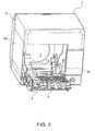
- FIG. 2 is an oblique view of the same printer with the cover completely open.
- the printer 1 has a rectangular box-like body 2 and a cover 3 that opens and closes and is disposed to the front of the body 2.
- a paper exit 4 of a specific width is formed at the front of the outside case 2a part of the printer body 2.
- An exit guide 5 projects to the front from the bottom of the paper exit 4, and a cover opening lever 6 is disposed beside the exit guide 5.
- a rectangular opening 2b for loading and removing roll paper is formed in the outside case 2a below the exit guide 5 and cover opening lever 6, and this opening 2b is closed by the cover 3.
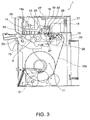
- FIG. 3 shows the internal configuration of the printer 1.
- Roll paper 12 is stored inside the roll paper compartment 11 so that the roll paper 12 can roll on its side between the sides of the printer.
- the roll paper 12 is a continuous web of paper 12a of a constant width wound into a roll.
- a head unit frame 13 is disposed horizontally at the top of the printer frame 10 above the roll paper compartment 11. Disposed to the head unit frame 13 are an inkjet head 14, a carriage 15 that carries the inkjet head 14, and a carriage guide shaft 16 that guides movement of the carriage 15 widthwise to the printer.
- the carriage guide shaft 16 is disposed horizontally widthwise to the printer.
- the inkjet head 14 is mounted on the carriage 15 with the ink nozzle surface 14a facing down.
- a carriage transportation mechanism including a carriage motor 17 and timing belt 18 for moving the carriage 15 bidirectionally along the carriage guide shaft 16 is disposed above the roll paper compartment 11.
- a platen 19 extending horizontally widthwise to the printer is disposed below the inkjet head 14 with a constant gap to the ink nozzle surface 14a.
- the platen 19 determines the printing position of the inkjet head 14.
- a tension guide 20 that curves downward is attached on the back side of the platen 19. The tension guide 20 is urged upward by a spring force, and the paper 12a pulled from the roll paper 12 stored in the roll paper compartment 11 is pulled through the paper transportation path passed the printing position with a specific amount of pressure applied thereto by the tension guide 20.
- a rear paper feed roller 21 and a rear paper pressure roller 22 are disposed horizontally widthwise to the printer behind the platen 19 (that is, on the upstream side in the transportation direction).
- the rear paper pressure roller 22 is pressed from above with a predetermined force to the rear paper feed roller 21 with the paper 12a therebetween.
- a front paper feed roller 23 and front paper pressure roller 24 are disposed on the front side of the platen 19 (downstream in the transportation direction).
- the front paper pressure roller 24 is pressed from above to the front paper feed roller 23 with the paper 12a therebetween.
- the rear paper feed roller 21 and the front paper feed roller 23 are rotationally driven synchronously by the paper transportation motor 25 disposed to the printer frame 10.
- a paper detector 26 is disposed to a paper detection position on the upstream side of the inkjet head 14 on the transportation path A.
- the paper detector 26 is a reflection photosensor or a transmission photosensor, and detects whether paper 12a is present or the type of paper 12a using the transmission or reflection of light from the paper 12a pulled through the transportation path A.
- An encoder sensor 27 mounted on the carriage 15 is disposed above the transportation path A.
- the encoder sensor 27 functions as a linear encoder in conjunction with a linear scale that extends through the range of bidirectional movement of the carriage 15, and functions as a position detector for detecting the positions of the carriage 15 and the inkjet head 14 widthwise to the printer. Note that instead of directly detecting the amount of carriage 15 and inkjet head 14 movement using the encoder sensor 27 and linear scale, the movement of the carriage 15 and inkjet head 14 widthwise to the printer may be calculated based on the detected rotation of the carriage motor 17 to determine the positions of the carriage 15 and inkjet head 14 widthwise to the printer.
- a paper width detector 29 is disposed to the carriage 15 at a position opposite the recording surface of the paper 12a.
- the paper width detector 29 is a reflection photosensor and detects the paper width in conjunction with movement of the carriage 15 widthwise to the printer (widthwise to the paper).
- the paper width detector 29 detects the left edge and right edge of the paper 12a at the paper width detection position of the platen 19 using reflection of light from the platen 19 or the paper 12a.
- the paper 12a pulled from the roll paper 12 in the roll paper compartment 11 is set with predetermined tension applied thereto by the tension guide 20 through the transportation path A (denoted by the bold dot-dash line in FIG. 3 ) passed the printing position of the platen 19 and out from the paper exit 4.
- the paper transportation motor 25 is driven with the paper 12a thus loaded, the rear paper feed roller 21 and front paper feed roller 23 turn and the paper 12a is advanced a predetermined distance.
- the inkjet head 14 is also driven synchronized to conveyance of the paper 12a to print on the surface of the paper 12a as it passes the printing position. Paper transportation is then stopped with the printed portion of the paper 12a hanging out from the paper exit 4, the leading portion of the paper 12a is cut by the paper cutter 28 disposed near the paper exit 4, and the printed portion of the paper is discharged.
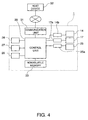
- FIG. 4 is a schematic block diagram showing the control system of the printer 1.
- the control system of the printer 1 is constructed around a control unit 30 including a CPU, ROM, and RAM.
- Nonvolatile memory 33 such as flash ROM is also connected to the control unit 30.
- Print data and commands are supplied from an external device such as a host device 32 through a communication unit 31 to the control unit 30. Based on print commands and other data from the host device 32, the control unit 30 controls driving the paper feed mechanism and the carriage transportation mechanism to convey the paper 12a to advance the print medium and print.
- the inkjet head 14 is connected to the output side of the control unit 30 through the print head driver 14b, and the control unit 30 controls driving the inkjet head 14 through the print head driver 14b.
- the carriage motor 17 and paper transportation motor 25 are connected to the output side of the control unit 30 through a motor driver 17a and motor driver 25a, and the control unit 30 controls driving the paper transportation motor 25 and carriage motor 17 through the motor drivers 25a and 17a.
- the control unit 30 can calculate the distance the paper 12a is conveyed by integrating the number of steps or the rotational distance that the paper transportation motor 25 is driven in the advancing direction.
- the paper detector 26 is connected to the input side of the control unit 30.
- the control unit 30 detects if the paper 12a is present on the transportation path A at the detection position where the paper detector 26 is disposed to the transportation path A based on the detected output of the paper detector 26.
- the control unit 30 may alternatively execute a paper type detection operation to determine at the paper detection position the type of paper that is loaded in the roll paper compartment 11. For example, the paper 12a that is pulled from the roll paper 12 and loaded in the transportation path A may be conveyed a predetermined distance and the type of paper that is used as the paper 12a may be determined based on the detected output of the paper detector 26.
- the control unit 30 can also optimize the printing operation for the paper.
- the encoder sensor 27 and the paper width detector 29 are also connected to the input side of the control unit 30.
- the control unit 30 executes the detection operation using the paper width detector 29 by controlling driving the carriage transportation mechanism to move the inkjet head 14 and the carriage 15 widthwise to the paper 12a set in the transportation path A.
- the control unit 30 compares the detection output of the paper width detector 29 with a predetermined threshold value to detect when the paper width detector 29 passes over the edge of the paper 12a.
- the width of the paper 12a is detected by detecting how far the carriage 15 moves between the left edge and right edge of the paper 12a based on the output of the encoder sensor 27.
- the left edge position and right edge position of the paper 12a may be detected by detecting how far the carriage 15 moves when the carriage 15 moves from the home position to the left edge and the right edge of the paper 12a.
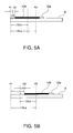
- FIG. 5A describes when the paper is set to an edge reference position
- FIG. 5B describes when the paper is set to the center reference position.
- the control unit 30 starts printing with the ink discharge nozzles of the inkjet head 14 positioned to the left edge of the printing area 12b defined for the paper 12a set to the transportation path A.
- the position of the left edge of the printing area 12b is the start printing position (printing reference position) of the inkjet head 14.
- the paper 12a When the paper 12a is set to the left-edge reference, the paper 12a is set so that the left edge of the paper 12a aligned with the left edge P1 of the transportation path A.
- the start printing position Q1 which is the position of the left edge of the printing area 12b, is the position moved to the right by the margin Lm on the left side of the printing area 12b of the paper 12a.
- the paper 12a is set to the center reference, the paper 12a is loaded with the center of the paper 12a aligned with the center P2 of the transportation path A.
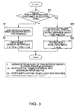
- the printer 1 When the printer 1 receives print data from the host device 32, it interprets the received print data. Based on the interpreted content, the printer 1 executes the process of determining the start printing position for printing the print data.
- FIG. 6 is a flow chart of the start printing position determination process.
- step S4 the default paper width previously stored in nonvolatile memory 33 is read, and this default paper width is used as the width of the paper 12a.
- the default paper width is set to the maximum paper width that can be set in the transportation path A, that is, width La is substantially equal to the width of the transportation path A.
- the paper width value that was previously received and stored in nonvolatile memory 33 may be read and used at this time.
- the width Lm of the margin on the left side of the paper 12a may be previously stored in the nonvolatile memory 33 of the printer 1, or it may be received from the host device 32.
- a default margin may be used if the size of the margin is not contained in the received data, and the received margin may be used if the margin is contained in the received data.
- the margin may be read from memory and used.
- FIG. 7 is a flow chart of the process determining the start printing position using only the center reference. Steps S11 to S14 in the decision process shown in FIG.
- step S7 are identical to steps S1 to S4 in the decision process shown in FIG. 6 .
- the process in FIG. 7 omits step S5, goes from step S4 to step S3, and determines the start printing position using the center-referenced determination method when using the default paper width.
- the printer 1 executes the paper feed operation and printing operation to print the received data.
- the process of detecting the width of the paper 12a by means of the paper width detector 29 is executed at the paper width detection position of the platen 19 before the operation of aligning the printing area of the paper 12a with the printing position of the platen 19 is completed.
- the width of the paper 12a being conveyed, and the positions of the left and right widthwise edges of the paper 12a are known.
- the control unit 30 detects the width by means of the paper width detector 29. Whether the set position of the paper determined from the received paper width information matches the detected position of the paper is determined. If these positions are determined to not match, a paper error results and an error handling process such as displaying a specific error message and stopping operation is executed.
- the result of detection by the paper width detector 29 may be prioritized and the printing area of the inkjet head 14 adjusted so that printing does not exceed the edges of the paper. For example, a masking process (that is, not printing) may be applied to the part of the print data that exceeds the width of the paper 12a set in the transportation path A, and the inkjet head 14 may be controlled to print only within the detected width of the paper.
- a printer 1 can determine whether to control printing referenced to the paper center by determining whether or not paper width information is contained in the received data, uses the center reference only if the paper width information is contained in the received data, and can adjust the start printing position of the inkjet head 14 according to the paper width. If the paper width information is not contained in the received data, the start printing position can be set so that printing is executed using a left-edge reference to paper 12a of a preset default paper width. A left-edge reference and a center reference can therefore be used appropriately as needed, and the printer 1 can print correctly to the printing area 12b of the paper 12a even if the paper 12a is sent to the center-referenced position.
- the roll paper 12 can therefore be loaded in the center of the roll paper compartment 11, and the ease of loading the roll paper 12 and operating stability can be improved. Furthermore, because it is not necessary to include the paper width information in the received data sent from the host device 32 when printing using a left-edge reference, the processing load of the printer 1 is reduced and faster processing is possible.
- This embodiment of the invention also determines the width of the paper 12a used for printing based on the received paper width information, and determines the start printing position referenced to the center for the paper 12a of the determined paper width.
- the roll paper 12 can be loaded in the center of the roll paper compartment 11 to improve the ease of loading the roll paper 12 and operating stability while the start printing position of the inkjet head 14 can be determined and content can be printed correctly within the printing area 12b of the paper 12a.
- this embodiment of the invention can determine the margins and paper width based on information that is previously stored or received from the host device 32 side, soiling of the platen 19 or shifting of the printing position caused by detection errors by the paper width detector 29 do not occur. Furthermore, because either an error state is entered or the printing width is adjusted so that content is only printed within the detected width of the paper when the detection result from the paper width detector 29 does not match the set position of the paper determined from the paper width information, problems such as soiling the platen 19 by discharging ink to positions outside of the paper can also be prevented.
- the paper width information may also be sent to the printer 1 at a different time than when the print data is sent.
Claims (10)
- Drucksteuerungsverfahren für einen Drucker (1), der dazu konfiguriert ist, mit einer Hostvorrichtung verbunden zu werden, um Papier (12a) durch einen Transportweg (A) zu befördern und zu bedrucken, während er einen auf einem Schlitten (15) angebrachten Druckkopf (14) bewegt, wobei,
wenn Papierbreiteninformation von der Hostvorrichtung empfangen wird, das Drucksteuerungsverfahren einen Schritt des Bestimmens umfasst, dass das Papier (12a) auf eine mittenbezogene Position eingestellt ist, welche eine Position ist, die auf die Mitte des Transportwegs (A) in der Papierbreitenrichtung bezogen ist, und,
wenn keine Papierbreiteninformation von der Hostvorrichtung empfangen wird, das Drucksteuerungsverfahren einen Schritt des Bestimmens umfasst, dass das Papier (12a) auf eine kantenbezogene Position eingestellt ist, welche eine Position ist, die auf eine Kante des Transportwegs (A) in der Papierbreitenrichtung bezogen ist, wenn keine Papierbreiteninformation von der Hostvorrichtung empfangen wird. - Drucksteuerungsverfahren nach Anspruch 1, wobei bestimmt wird, dass das Papier (12a) auf die kantenbezogene Position eingestellt ist, wenn Druckdaten von der Hostvorrichtung ohne Papierbreiteninformation empfangen werden.
- Drucksteuerungsverfahren nach Anspruch 1 oder 2, weiterhin mit dem folgenden Schritt;
Bestimmen einer Druckbezugsposition zum Drucken auf der Grundlage der mittenbezogenen Position, wenn die Papierbreiteninformation empfangen wird. - Drucksteuerungsverfahren für einen Drucker nach mindestens einem der Ansprüche 1 bis 3, weiterhin mit dem folgenden Schritt:Bestimmen einer Druckbezugsposition zum Drucken auf der Grundlage der kantenbezogenen Position, wenn die Papierbreiteninformation nicht empfangen wird.
- Drucksteuerungsverfahren nach Anspruch 3 oder Anspruch 4, wobei:die Druckbezugsposition die Startdruckposition (Q1; Q2) des Druckkopfs (14) ist.
- Drucksteuerungsverfahren nach mindestens einem der Ansprüche 1 bis 5, wobei:die maximale Breite des Papiers (12a), die im Transportweg (A) eingestellt werden kann, in einem Speicher (33) vorab gespeichert ist; und,wenn ohne Empfang der Papierbreiteninformation gedruckt wird,die maximale Papierbreite als die Papierbreite des zum Drucken verwendeten Papiers (12a) eingestellt wird, undder Abstand L von der Kante des Transportwegs zur Startdruckposition (Q1) auf
 eingestellt wird, wobei Lm für einen Rand auf einer Seite des Papiers steht.
 - Drucksteuerungsverfahren nach mindestens einem der Ansprüche 1 bis 6, wobei:wenn nach dem Empfang der Papierbreiteninformation gedruckt wird, der Abstand L von einer Kante des Transportwegs (A) zur Startdruckposition (Q2) auf
 eingestellt wird, wobei La für die Breite des Transportwegs (A) steht, Lb für die Breite des zum Drucken verwendeten Papiers (12a) steht und Lm für einen Rand auf einer Seite des Papiers (12a) steht.
 - Drucksteuerungsverfahren nach mindestens einem der Ansprüche 1 bis 7, wobei:eine Papiererfassungsvorrichtung (26) auf dem Schlitten (15) zum Erfassen elner Position von Papier auf dem Transportweg (A) angebracht ist; und,wenn eine erfasste Papierposition des Papiers (12a) auf dem Transportweg (A), die eine Position des Papiers (12a) ist, die von der Papierertassungsvorrichtung (26) erfasst wird, nachdem die Papierbreiteninformation von der Hostvorrichtung empfangen worden ist, und die Position des Papiers (12a), die auf der Grundlage der empfangenen Papierbreiteninformation bestimmt wird, nicht übereinstimmen, ein spezifischer Fehlerzustand eingegeben wird und/oder das Drucken mittels des Druckkopfes (14) nur innerhalb des Bereichs der erfassten Papierposition ausgeführt wird.
- Drucker mit:einer Steuereinheit (30) zum Ausführen des Drucksteuerungsverfahrens nach mindestens einem der Ansprüche 1 bis 8 und Bestimmen einer Papierbezugsposition.
- Drucker nach Anspruch 9, wobei:das Papier (12a) Rollenpapier (12) ist; unddas Rollenpapier (12) in ein Hollenpapierfach (11) eingelegt ist.
Applications Claiming Priority (1)
| Application Number | Priority Date | Filing Date | Title |
|---|---|---|---|
| JP2008199361A JP5176762B2 (ja) | 2008-08-01 | 2008-08-01 | プリンタにおける印刷制御方法およびプリンタ |
Publications (2)
| Publication Number | Publication Date |
|---|---|
| EP2149455A1 EP2149455A1 (de) | 2010-02-03 |
| EP2149455B1 true EP2149455B1 (de) | 2011-12-28 |
Family
ID=41092064
Family Applications (1)
| Application Number | Title | Priority Date | Filing Date |
|---|---|---|---|
| EP09166647A Not-in-force EP2149455B1 (de) | 2008-08-01 | 2009-07-28 | Verfahren zur Steuerung des Druckens in einem Drucker, sowie Drucker |
Country Status (5)
| Country | Link |
|---|---|
| US (2) | US8414099B2 (de) |
| EP (1) | EP2149455B1 (de) |
| JP (1) | JP5176762B2 (de) |
| CN (1) | CN101638013B (de) |
| AT (1) | ATE538939T1 (de) |
Families Citing this family (8)
| Publication number | Priority date | Publication date | Assignee | Title |
|---|---|---|---|---|
| JP5176762B2 (ja) * | 2008-08-01 | 2013-04-03 | セイコーエプソン株式会社 | プリンタにおける印刷制御方法およびプリンタ |
| US8879117B2 (en) | 2010-05-26 | 2014-11-04 | Hewlett-Packard Development Company, L.P. | Margin adjustment |
| KR101284188B1 (ko) * | 2012-01-16 | 2013-07-09 | 주식회사 빅솔론 | 포스용 프린터의 용지 간격 조절장치 |
| JP6238599B2 (ja) * | 2013-06-28 | 2017-11-29 | キヤノン株式会社 | 印刷制御装置、印刷制御方法、およびプログラム |
| JP6366231B2 (ja) * | 2013-06-28 | 2018-08-01 | キヤノン株式会社 | 印刷装置、印刷装置の制御方法、およびプログラム |
| US9701135B2 (en) | 2015-01-30 | 2017-07-11 | S-Printing Solution Co., Ltd. | Image forming apparatus, recording medium, terminal, server, note printing method, and storage medium |
| JP6729239B2 (ja) * | 2016-09-21 | 2020-07-22 | セイコーエプソン株式会社 | 印刷装置および印刷装置の制御方法 |
| JP7282585B2 (ja) * | 2019-04-24 | 2023-05-29 | キヤノン株式会社 | 情報処理装置、記録装置、記録媒体の決定方法、及びプログラム |
Family Cites Families (18)
| Publication number | Priority date | Publication date | Assignee | Title |
|---|---|---|---|---|
| JPS5993374A (ja) * | 1982-11-19 | 1984-05-29 | Canon Inc | 印字方式 |
| JPS6120780A (ja) * | 1984-07-09 | 1986-01-29 | Sharp Corp | プリンタの紙押え装置 |
| JPS6416345A (en) | 1987-07-11 | 1989-01-19 | Tsudakoma Ind Co Ltd | Pneumatic flotation type drive unit |
| JP2947414B2 (ja) * | 1988-05-06 | 1999-09-13 | 東芝テック株式会社 | プリンタ |
| JPH04158078A (ja) * | 1990-10-23 | 1992-06-01 | Seikosha Co Ltd | シリアルプリンタ |
| JPH08221238A (ja) | 1995-02-15 | 1996-08-30 | Nec Corp | プリンタの用紙寸法設定方式 |
| JPH1016345A (ja) * | 1996-06-28 | 1998-01-20 | Sharp Corp | 文書処理装置 |
| US6594028B1 (en) * | 1999-04-14 | 2003-07-15 | Canon Kabushiki Kaisha | Status-based control over printer |
| JP2001030565A (ja) * | 1999-07-21 | 2001-02-06 | Sato Corp | 印刷装置および印刷制御方法、並びに記録媒体 |
| JP2003095482A (ja) * | 2001-09-21 | 2003-04-03 | Canon Inc | 画像形成装置 |
| JP2004358672A (ja) | 2003-06-02 | 2004-12-24 | Canon Inc | 印刷装置 |
| JP2005088303A (ja) | 2003-09-16 | 2005-04-07 | Fuji Photo Film Co Ltd | 画像記録装置及び方法 |
| CN101037056A (zh) * | 2004-03-31 | 2007-09-19 | 明基电通股份有限公司 | 打印系统及其校正喷墨位置的方法 |
| US7207637B2 (en) * | 2004-04-07 | 2007-04-24 | King Slide Works Co., Ltd. | Coupling apparatus for a side panel and a face panel of drawers |
| JP2006106485A (ja) * | 2004-10-07 | 2006-04-20 | Canon Inc | 画像形成装置 |
| JP4379366B2 (ja) * | 2005-03-29 | 2009-12-09 | ブラザー工業株式会社 | 媒体端部検出装置及び画像記録装置 |
| JP4761511B2 (ja) * | 2005-04-20 | 2011-08-31 | リョービ株式会社 | 枚葉印刷機の位置決め装置およびその制御方法 |
| JP5176762B2 (ja) | 2008-08-01 | 2013-04-03 | セイコーエプソン株式会社 | プリンタにおける印刷制御方法およびプリンタ |
-
2008
- 2008-08-01 JP JP2008199361A patent/JP5176762B2/ja not_active Expired - Fee Related
-
2009
- 2009-07-24 CN CN2009101601353A patent/CN101638013B/zh not_active Expired - Fee Related
- 2009-07-28 EP EP09166647A patent/EP2149455B1/de not_active Not-in-force
- 2009-07-28 AT AT09166647T patent/ATE538939T1/de active
- 2009-08-03 US US12/534,454 patent/US8414099B2/en active Active
-
2013
- 2013-03-05 US US13/785,473 patent/US8696084B2/en not_active Expired - Fee Related
Also Published As
| Publication number | Publication date |
|---|---|
| US20100025450A1 (en) | 2010-02-04 |
| US20130235109A1 (en) | 2013-09-12 |
| EP2149455A1 (de) | 2010-02-03 |
| CN101638013B (zh) | 2011-06-15 |
| JP2010036381A (ja) | 2010-02-18 |
| US8414099B2 (en) | 2013-04-09 |
| US8696084B2 (en) | 2014-04-15 |
| ATE538939T1 (de) | 2012-01-15 |
| JP5176762B2 (ja) | 2013-04-03 |
| CN101638013A (zh) | 2010-02-03 |
Similar Documents
| Publication | Publication Date | Title |
|---|---|---|
| US8696084B2 (en) | Method of controlling printing in a printer, and a printer | |
| US8029083B2 (en) | Recording medium detection method and label printer | |
| EP3299175B1 (de) | Drucker und druckeransteuerungsverfahren | |
| US8711389B2 (en) | Printing control method and printer for printing on a label | |
| US8646996B2 (en) | Method of setting paper in a printer, and a printer | |
| JP4517926B2 (ja) | プリンタの記録紙ローディング方法 | |
| US5738457A (en) | Paper size determining method and printer in which the method is used | |
| JP2010023297A (ja) | プリンタの制御方法およびプリンタ | |
| JP5146175B2 (ja) | プリンタの印刷位置制御方法およびプリンタ | |
| JP2010030190A (ja) | 記録紙の位置決め方法およびプリンタ | |
| JP5556912B2 (ja) | プリンタにおける印刷制御方法およびプリンタ | |
| JP5609999B2 (ja) | プリンタの再印刷制御方法およびプリンタ | |
| US10343428B2 (en) | Printing apparatus and paper supply apparatus | |
| JP2010023386A (ja) | プリンタにおける記録紙の切断方法およびプリンタ | |
| JP5946346B2 (ja) | ラベル搬送装置、ラベルプリンタ、センサの調整方法 | |
| JP2010030188A (ja) | プリンタの印刷位置制御方法およびプリンタ | |
| JP2010023387A (ja) | プリンタにおける記録紙の切断方法およびプリンタ | |
| JP7035568B2 (ja) | 印刷装置、及び、印刷装置の制御方法 | |
| JP2023095543A (ja) | 印刷装置 | |
| JPH11314414A (ja) | 画像記録装置 | |
| JP2010131925A (ja) | 長尺状の消耗品のニアエンド検出方法および印刷装置 | |
| JP2010036441A (ja) | オートローディング制御方法およびプリンタ |
Legal Events
| Date | Code | Title | Description |
|---|---|---|---|
| PUAI | Public reference made under article 153(3) epc to a published international application that has entered the european phase |
Free format text: ORIGINAL CODE: 0009012 |
|
| AK | Designated contracting states |
Kind code of ref document: A1 Designated state(s): AT BE BG CH CY CZ DE DK EE ES FI FR GB GR HR HU IE IS IT LI LT LU LV MC MK MT NL NO PL PT RO SE SI SK SM TR |
|
| 17P | Request for examination filed |
Effective date: 20100803 |
|
| RIN1 | Information on inventor provided before grant (corrected) |
Inventor name: NAKAMAKI, MOTOHIRO |
|
| GRAP | Despatch of communication of intention to grant a patent |
Free format text: ORIGINAL CODE: EPIDOSNIGR1 |
|
| GRAJ | Information related to disapproval of communication of intention to grant by the applicant or resumption of examination proceedings by the epo deleted |
Free format text: ORIGINAL CODE: EPIDOSDIGR1 |
|
| GRAP | Despatch of communication of intention to grant a patent |
Free format text: ORIGINAL CODE: EPIDOSNIGR1 |
|
| GRAS | Grant fee paid |
Free format text: ORIGINAL CODE: EPIDOSNIGR3 |
|
| GRAA | (expected) grant |
Free format text: ORIGINAL CODE: 0009210 |
|
| RAP1 | Party data changed (applicant data changed or rights of an application transferred) |
Owner name: SEIKO EPSON CORPORATION |
|
| AK | Designated contracting states |
Kind code of ref document: B1 Designated state(s): AT BE BG CH CY CZ DE DK EE ES FI FR GB GR HR HU IE IS IT LI LT LU LV MC MK MT NL NO PL PT RO SE SI SK SM TR |
|
| REG | Reference to a national code |
Ref country code: GB Ref legal event code: FG4D |
|
| REG | Reference to a national code |
Ref country code: CH Ref legal event code: EP |
|
| REG | Reference to a national code |
Ref country code: AT Ref legal event code: REF Ref document number: 538939 Country of ref document: AT Kind code of ref document: T Effective date: 20120115 |
|
| REG | Reference to a national code |
Ref country code: IE Ref legal event code: FG4D |
|
| REG | Reference to a national code |
Ref country code: DE Ref legal event code: R096 Ref document number: 602009004330 Country of ref document: DE Effective date: 20120301 |
|
| REG | Reference to a national code |
Ref country code: NL Ref legal event code: VDEP Effective date: 20111228 |
|
| PG25 | Lapsed in a contracting state [announced via postgrant information from national office to epo] |
Ref country code: LT Free format text: LAPSE BECAUSE OF FAILURE TO SUBMIT A TRANSLATION OF THE DESCRIPTION OR TO PAY THE FEE WITHIN THE PRESCRIBED TIME-LIMIT Effective date: 20111228 Ref country code: NO Free format text: LAPSE BECAUSE OF FAILURE TO SUBMIT A TRANSLATION OF THE DESCRIPTION OR TO PAY THE FEE WITHIN THE PRESCRIBED TIME-LIMIT Effective date: 20120328 |
|
| LTIE | Lt: invalidation of european patent or patent extension |
Effective date: 20111228 |
|
| PG25 | Lapsed in a contracting state [announced via postgrant information from national office to epo] |
Ref country code: GR Free format text: LAPSE BECAUSE OF FAILURE TO SUBMIT A TRANSLATION OF THE DESCRIPTION OR TO PAY THE FEE WITHIN THE PRESCRIBED TIME-LIMIT Effective date: 20120329 Ref country code: SI Free format text: LAPSE BECAUSE OF FAILURE TO SUBMIT A TRANSLATION OF THE DESCRIPTION OR TO PAY THE FEE WITHIN THE PRESCRIBED TIME-LIMIT Effective date: 20111228 Ref country code: LV Free format text: LAPSE BECAUSE OF FAILURE TO SUBMIT A TRANSLATION OF THE DESCRIPTION OR TO PAY THE FEE WITHIN THE PRESCRIBED TIME-LIMIT Effective date: 20111228 Ref country code: SE Free format text: LAPSE BECAUSE OF FAILURE TO SUBMIT A TRANSLATION OF THE DESCRIPTION OR TO PAY THE FEE WITHIN THE PRESCRIBED TIME-LIMIT Effective date: 20111228 Ref country code: HR Free format text: LAPSE BECAUSE OF FAILURE TO SUBMIT A TRANSLATION OF THE DESCRIPTION OR TO PAY THE FEE WITHIN THE PRESCRIBED TIME-LIMIT Effective date: 20111228 |
|
| PG25 | Lapsed in a contracting state [announced via postgrant information from national office to epo] |
Ref country code: BE Free format text: LAPSE BECAUSE OF FAILURE TO SUBMIT A TRANSLATION OF THE DESCRIPTION OR TO PAY THE FEE WITHIN THE PRESCRIBED TIME-LIMIT Effective date: 20111228 Ref country code: CY Free format text: LAPSE BECAUSE OF FAILURE TO SUBMIT A TRANSLATION OF THE DESCRIPTION OR TO PAY THE FEE WITHIN THE PRESCRIBED TIME-LIMIT Effective date: 20111228 |
|
| PG25 | Lapsed in a contracting state [announced via postgrant information from national office to epo] |
Ref country code: CZ Free format text: LAPSE BECAUSE OF FAILURE TO SUBMIT A TRANSLATION OF THE DESCRIPTION OR TO PAY THE FEE WITHIN THE PRESCRIBED TIME-LIMIT Effective date: 20111228 Ref country code: BG Free format text: LAPSE BECAUSE OF FAILURE TO SUBMIT A TRANSLATION OF THE DESCRIPTION OR TO PAY THE FEE WITHIN THE PRESCRIBED TIME-LIMIT Effective date: 20120328 Ref country code: NL Free format text: LAPSE BECAUSE OF FAILURE TO SUBMIT A TRANSLATION OF THE DESCRIPTION OR TO PAY THE FEE WITHIN THE PRESCRIBED TIME-LIMIT Effective date: 20111228 Ref country code: SK Free format text: LAPSE BECAUSE OF FAILURE TO SUBMIT A TRANSLATION OF THE DESCRIPTION OR TO PAY THE FEE WITHIN THE PRESCRIBED TIME-LIMIT Effective date: 20111228 Ref country code: EE Free format text: LAPSE BECAUSE OF FAILURE TO SUBMIT A TRANSLATION OF THE DESCRIPTION OR TO PAY THE FEE WITHIN THE PRESCRIBED TIME-LIMIT Effective date: 20111228 Ref country code: IS Free format text: LAPSE BECAUSE OF FAILURE TO SUBMIT A TRANSLATION OF THE DESCRIPTION OR TO PAY THE FEE WITHIN THE PRESCRIBED TIME-LIMIT Effective date: 20120428 |
|
| PG25 | Lapsed in a contracting state [announced via postgrant information from national office to epo] |
Ref country code: RO Free format text: LAPSE BECAUSE OF FAILURE TO SUBMIT A TRANSLATION OF THE DESCRIPTION OR TO PAY THE FEE WITHIN THE PRESCRIBED TIME-LIMIT Effective date: 20111228 Ref country code: PL Free format text: LAPSE BECAUSE OF FAILURE TO SUBMIT A TRANSLATION OF THE DESCRIPTION OR TO PAY THE FEE WITHIN THE PRESCRIBED TIME-LIMIT Effective date: 20111228 Ref country code: PT Free format text: LAPSE BECAUSE OF FAILURE TO SUBMIT A TRANSLATION OF THE DESCRIPTION OR TO PAY THE FEE WITHIN THE PRESCRIBED TIME-LIMIT Effective date: 20120430 |
|
| REG | Reference to a national code |
Ref country code: AT Ref legal event code: MK05 Ref document number: 538939 Country of ref document: AT Kind code of ref document: T Effective date: 20111228 |
|
| PG25 | Lapsed in a contracting state [announced via postgrant information from national office to epo] |
Ref country code: DK Free format text: LAPSE BECAUSE OF FAILURE TO SUBMIT A TRANSLATION OF THE DESCRIPTION OR TO PAY THE FEE WITHIN THE PRESCRIBED TIME-LIMIT Effective date: 20111228 |
|
| PLBE | No opposition filed within time limit |
Free format text: ORIGINAL CODE: 0009261 |
|
| STAA | Information on the status of an ep patent application or granted ep patent |
Free format text: STATUS: NO OPPOSITION FILED WITHIN TIME LIMIT |
|
| PG25 | Lapsed in a contracting state [announced via postgrant information from national office to epo] |
Ref country code: IT Free format text: LAPSE BECAUSE OF FAILURE TO SUBMIT A TRANSLATION OF THE DESCRIPTION OR TO PAY THE FEE WITHIN THE PRESCRIBED TIME-LIMIT Effective date: 20111228 |
|
| 26N | No opposition filed |
Effective date: 20121001 |
|
| REG | Reference to a national code |
Ref country code: DE Ref legal event code: R097 Ref document number: 602009004330 Country of ref document: DE Effective date: 20121001 |
|
| PG25 | Lapsed in a contracting state [announced via postgrant information from national office to epo] |
Ref country code: AT Free format text: LAPSE BECAUSE OF FAILURE TO SUBMIT A TRANSLATION OF THE DESCRIPTION OR TO PAY THE FEE WITHIN THE PRESCRIBED TIME-LIMIT Effective date: 20111228 |
|
| PG25 | Lapsed in a contracting state [announced via postgrant information from national office to epo] |
Ref country code: MC Free format text: LAPSE BECAUSE OF NON-PAYMENT OF DUE FEES Effective date: 20120731 Ref country code: MK Free format text: LAPSE BECAUSE OF FAILURE TO SUBMIT A TRANSLATION OF THE DESCRIPTION OR TO PAY THE FEE WITHIN THE PRESCRIBED TIME-LIMIT Effective date: 20111228 |
|
| PG25 | Lapsed in a contracting state [announced via postgrant information from national office to epo] |
Ref country code: ES Free format text: LAPSE BECAUSE OF FAILURE TO SUBMIT A TRANSLATION OF THE DESCRIPTION OR TO PAY THE FEE WITHIN THE PRESCRIBED TIME-LIMIT Effective date: 20120408 |
|
| REG | Reference to a national code |
Ref country code: IE Ref legal event code: MM4A |
|
| PG25 | Lapsed in a contracting state [announced via postgrant information from national office to epo] |
Ref country code: FI Free format text: LAPSE BECAUSE OF FAILURE TO SUBMIT A TRANSLATION OF THE DESCRIPTION OR TO PAY THE FEE WITHIN THE PRESCRIBED TIME-LIMIT Effective date: 20111228 |
|
| PG25 | Lapsed in a contracting state [announced via postgrant information from national office to epo] |
Ref country code: IE Free format text: LAPSE BECAUSE OF NON-PAYMENT OF DUE FEES Effective date: 20120728 Ref country code: MT Free format text: LAPSE BECAUSE OF FAILURE TO SUBMIT A TRANSLATION OF THE DESCRIPTION OR TO PAY THE FEE WITHIN THE PRESCRIBED TIME-LIMIT Effective date: 20111228 |
|
| REG | Reference to a national code |
Ref country code: CH Ref legal event code: PL |
|
| PG25 | Lapsed in a contracting state [announced via postgrant information from national office to epo] |
Ref country code: TR Free format text: LAPSE BECAUSE OF FAILURE TO SUBMIT A TRANSLATION OF THE DESCRIPTION OR TO PAY THE FEE WITHIN THE PRESCRIBED TIME-LIMIT Effective date: 20111228 Ref country code: LI Free format text: LAPSE BECAUSE OF NON-PAYMENT OF DUE FEES Effective date: 20130731 Ref country code: CH Free format text: LAPSE BECAUSE OF NON-PAYMENT OF DUE FEES Effective date: 20130731 |
|
| PG25 | Lapsed in a contracting state [announced via postgrant information from national office to epo] |
Ref country code: SM Free format text: LAPSE BECAUSE OF FAILURE TO SUBMIT A TRANSLATION OF THE DESCRIPTION OR TO PAY THE FEE WITHIN THE PRESCRIBED TIME-LIMIT Effective date: 20111228 Ref country code: LU Free format text: LAPSE BECAUSE OF NON-PAYMENT OF DUE FEES Effective date: 20120728 |
|
| PG25 | Lapsed in a contracting state [announced via postgrant information from national office to epo] |
Ref country code: HU Free format text: LAPSE BECAUSE OF FAILURE TO SUBMIT A TRANSLATION OF THE DESCRIPTION OR TO PAY THE FEE WITHIN THE PRESCRIBED TIME-LIMIT Effective date: 20090728 |
|
| REG | Reference to a national code |
Ref country code: FR Ref legal event code: PLFP Year of fee payment: 8 |
|
| REG | Reference to a national code |
Ref country code: FR Ref legal event code: PLFP Year of fee payment: 9 |
|
| REG | Reference to a national code |
Ref country code: FR Ref legal event code: PLFP Year of fee payment: 10 |
|
| PGFP | Annual fee paid to national office [announced via postgrant information from national office to epo] |
Ref country code: FR Payment date: 20200611 Year of fee payment: 12 |
|
| PGFP | Annual fee paid to national office [announced via postgrant information from national office to epo] |
Ref country code: DE Payment date: 20200714 Year of fee payment: 12 Ref country code: GB Payment date: 20200716 Year of fee payment: 12 |
|
| REG | Reference to a national code |
Ref country code: DE Ref legal event code: R119 Ref document number: 602009004330 Country of ref document: DE |
|
| GBPC | Gb: european patent ceased through non-payment of renewal fee |
Effective date: 20210728 |
|
| PG25 | Lapsed in a contracting state [announced via postgrant information from national office to epo] |
Ref country code: GB Free format text: LAPSE BECAUSE OF NON-PAYMENT OF DUE FEES Effective date: 20210728 Ref country code: DE Free format text: LAPSE BECAUSE OF NON-PAYMENT OF DUE FEES Effective date: 20220201 |
|
| PG25 | Lapsed in a contracting state [announced via postgrant information from national office to epo] |
Ref country code: FR Free format text: LAPSE BECAUSE OF NON-PAYMENT OF DUE FEES Effective date: 20210731 |