EP2140954B1 - Procédé et dispositif de fabrication de parties coupantes fines d'une bande de matériau - Google Patents
Procédé et dispositif de fabrication de parties coupantes fines d'une bande de matériau Download PDFInfo
- Publication number
- EP2140954B1 EP2140954B1 EP20080012011 EP08012011A EP2140954B1 EP 2140954 B1 EP2140954 B1 EP 2140954B1 EP 20080012011 EP20080012011 EP 20080012011 EP 08012011 A EP08012011 A EP 08012011A EP 2140954 B1 EP2140954 B1 EP 2140954B1
- Authority
- EP
- European Patent Office
- Prior art keywords
- cutting
- die
- material strip
- fine blanking
- strip
- Prior art date
- Legal status (The legal status is an assumption and is not a legal conclusion. Google has not performed a legal analysis and makes no representation as to the accuracy of the status listed.)
- Not-in-force
Links
Images


Classifications
-
- B—PERFORMING OPERATIONS; TRANSPORTING
- B21—MECHANICAL METAL-WORKING WITHOUT ESSENTIALLY REMOVING MATERIAL; PUNCHING METAL
- B21D—WORKING OR PROCESSING OF SHEET METAL OR METAL TUBES, RODS OR PROFILES WITHOUT ESSENTIALLY REMOVING MATERIAL; PUNCHING METAL
- B21D28/00—Shaping by press-cutting; Perforating
- B21D28/02—Punching blanks or articles with or without obtaining scrap; Notching
- B21D28/10—Incompletely punching in such a manner that the parts are still coherent with the work
-
- B—PERFORMING OPERATIONS; TRANSPORTING
- B21—MECHANICAL METAL-WORKING WITHOUT ESSENTIALLY REMOVING MATERIAL; PUNCHING METAL
- B21D—WORKING OR PROCESSING OF SHEET METAL OR METAL TUBES, RODS OR PROFILES WITHOUT ESSENTIALLY REMOVING MATERIAL; PUNCHING METAL
- B21D28/00—Shaping by press-cutting; Perforating
- B21D28/02—Punching blanks or articles with or without obtaining scrap; Notching
- B21D28/16—Shoulder or burr prevention, e.g. fine-blanking
-
- B—PERFORMING OPERATIONS; TRANSPORTING
- B21—MECHANICAL METAL-WORKING WITHOUT ESSENTIALLY REMOVING MATERIAL; PUNCHING METAL
- B21D—WORKING OR PROCESSING OF SHEET METAL OR METAL TUBES, RODS OR PROFILES WITHOUT ESSENTIALLY REMOVING MATERIAL; PUNCHING METAL
- B21D45/00—Ejecting or stripping-off devices arranged in machines or tools dealt with in this subclass
- B21D45/003—Ejecting or stripping-off devices arranged in machines or tools dealt with in this subclass in punching machines or punching tools
-
- Y—GENERAL TAGGING OF NEW TECHNOLOGICAL DEVELOPMENTS; GENERAL TAGGING OF CROSS-SECTIONAL TECHNOLOGIES SPANNING OVER SEVERAL SECTIONS OF THE IPC; TECHNICAL SUBJECTS COVERED BY FORMER USPC CROSS-REFERENCE ART COLLECTIONS [XRACs] AND DIGESTS
- Y10—TECHNICAL SUBJECTS COVERED BY FORMER USPC
- Y10T—TECHNICAL SUBJECTS COVERED BY FORMER US CLASSIFICATION
- Y10T83/00—Cutting
- Y10T83/04—Processes
- Y10T83/0448—With subsequent handling [i.e., of product]
- Y10T83/0467—By separating products from each other
-
- Y—GENERAL TAGGING OF NEW TECHNOLOGICAL DEVELOPMENTS; GENERAL TAGGING OF CROSS-SECTIONAL TECHNOLOGIES SPANNING OVER SEVERAL SECTIONS OF THE IPC; TECHNICAL SUBJECTS COVERED BY FORMER USPC CROSS-REFERENCE ART COLLECTIONS [XRACs] AND DIGESTS
- Y10—TECHNICAL SUBJECTS COVERED BY FORMER USPC
- Y10T—TECHNICAL SUBJECTS COVERED BY FORMER US CLASSIFICATION
- Y10T83/00—Cutting
- Y10T83/04—Processes
- Y10T83/0524—Plural cutting steps
- Y10T83/0529—Blanking and cutting
-
- Y—GENERAL TAGGING OF NEW TECHNOLOGICAL DEVELOPMENTS; GENERAL TAGGING OF CROSS-SECTIONAL TECHNOLOGIES SPANNING OVER SEVERAL SECTIONS OF THE IPC; TECHNICAL SUBJECTS COVERED BY FORMER USPC CROSS-REFERENCE ART COLLECTIONS [XRACs] AND DIGESTS
- Y10—TECHNICAL SUBJECTS COVERED BY FORMER USPC
- Y10T—TECHNICAL SUBJECTS COVERED BY FORMER US CLASSIFICATION
- Y10T83/00—Cutting
- Y10T83/04—Processes
- Y10T83/06—Blanking
-
- Y—GENERAL TAGGING OF NEW TECHNOLOGICAL DEVELOPMENTS; GENERAL TAGGING OF CROSS-SECTIONAL TECHNOLOGIES SPANNING OVER SEVERAL SECTIONS OF THE IPC; TECHNICAL SUBJECTS COVERED BY FORMER USPC CROSS-REFERENCE ART COLLECTIONS [XRACs] AND DIGESTS
- Y10—TECHNICAL SUBJECTS COVERED BY FORMER USPC
- Y10T—TECHNICAL SUBJECTS COVERED BY FORMER US CLASSIFICATION
- Y10T83/00—Cutting
- Y10T83/202—With product handling means
- Y10T83/2074—Including means to divert one portion of product from another
- Y10T83/2079—Remaining or re-inserted product portion from base material
Definitions
- the invention relates to a method for producing fine blanking parts from a strip of material in a fine blanking tool, in which a strip of material is clamped between two tool parts or between an upper press or guide plate and a lower cutting plate and an upper and lower cutting punch and the cutting in cooperation with the upper wherein the cutting is carried out as an unfinished complete cut along the circumference of the fine blanking part with a specially shaped cutting edge of the cutting punch and / or cutting plate so that the fine blanking part at partial connecting parts on the material strip approximately at its upper or lower level in an altitude the material strip initially remains materially bonded and then moved together with the strip of material in the direction of the strip to a subsequent demolding stage (see JP 11309522 A ,
- the invention further relates to an apparatus for producing fine cutting parts of a strip of material, with at least one cutting plate and a cutting punch for cutting the fine cutting part of a strip of material. ).
- From the DE 10 2004 032 826 A1 is a method for producing stamped parts in a tool, in particular fine blanking tool, by means of at least one stamp, with which the stamped part is pushed out of a strip of material known.
- the punched part is pushed from the material strip of this after being pressed out to a discharge.
- the punch cooperates with a counter-holder in an insert when pressing out the stamped part, wherein the counter-holder the stamped part is lifted when opening the tool to the surface of the insert and the strip of material from the insert.
- the strip of material is lifted by the cutting plate at a defined distance which corresponds at least to the thickness of the stamped parts.
- the present invention seeks to improve a method and apparatus for producing fineblanked parts such that a vertical relative movement between strip of material and fineblanking part is completely avoided, reduces the necessary opening and closing of the device and a simple structure the device is a use on high-speed presses possible, the fineblanking parts suffer no damage to the functional surfaces.
- the solution according to the invention is characterized in that, for cutting, a die insert which can be inserted in a receptacle of the insert and a punch used with partially formed bevels along its cutting edges are used, and in the demolding step the partial bond parts are separated from the strip of material without pushing back
- the fine blanking part and the material strip are demolded downwards by a shear force-free breaking perpendicular to the running direction of the material strip, wherein the demoulded fine blanking part is removed through a chute in the cutting plate.
- the fine blanking part is cut to about 80 to 90% of its circumference completely from the strip of material.
- the fineblanking part is held on the material strip by at least one, in particular two or more, connecting part (s). These connection parts are to be arranged so that they do not come to lie in the area of the important functional surfaces of the fineblanking part during later breaking.
- connection points between the material strip and the fineblanking part are produced by the special shaping at the cutting edges of cutting punches and / or cutting plates in conjunction with the kinematics of the fineblanking press used, which are independent of the Thick variations of the material strip always moves in the same vertical position of the two decisive cutting edges.
- a recording of the insert at least one Matrizendon is inserted interchangeable and associated with a die insert opposite cutting punch with partially shaped chamfers along their cutting edges.
- the die insert is kept evenly biased along its circumference in the receptacle and projects beyond the base plate of the insert such that the die insert punctures the strip of material when closing the device on the punch, i. predetermined locations, can clamp without the base plate can engage.
- the ready-held enemy cutting oil not only distributes the areal pressure unintentionally and then is no longer available to a sufficient extent when cutting.
- the concentration of the fine cutting specific clamping forces on the die inserts continues to have the Advantage that the production of smooth cut surfaces on fineblanking part is supported.
- the demoulding process by breaking the connecting parts between the fineblank part and the material strip in the demoulding stage must ensure that no vertical shear forces are transmitted to the narrow connecting parts.
- the inventive device is simple and compact and has the great advantage that the required way to open and close the upper and lower part is significantly reduced. This is achieved in that in a receiving space of the cutting plate is arranged under a uniform bias force-locking die insert is associated with the cutting punch, wherein the cutting edges of the die insert and / or the cutting punch by a partially shaped barrel for incomplete cutting of Feinschneidteils from the strip of material are interrupted, such that the fine blanking part and the strip of material by partial connecting parts are materially interconnected after cutting, and that the die insert relative to the cutting plate has a vertical offset for partial clamping of the strip of material on a press or guide plate, and that in the cutting plate Downshaft for discharging the separated by a shear-free breaking off the strip of material fine cutting parts is provided vertically downwards to the direction of the strip of material.
- the special shaping of the cutting edges of die insert and / or punch consists of a partially shaped chamfer, which can vary in length and / or three and / or inclination and interrupts the cutting edge of Matrizenmony and / or cutting punch accordingly, so that the fine cutting part of the strip of material not is completely cut and remains firmly bonded to partial connecting parts on the material strip approximately at its upper or lower level in an altitude relative to the material strip.
- the space required for the transport of the composite of strips of material and fine blanking space within the interior of the device is achieved in that the die insert relative to the cutting plate has a height offset, which is dimensioned so that the required space for the material thickness downwardly protruding, however is still ensured on the strip of material fineblanking parts, so that the fineblanking parts can not be pushed back in the vertical direction or otherwise moved.
- the opposite to the cutting plate protruding die inserts allow for clamping the strip of material and a concentration of fine cutting specific clamping forces around the cutting geometry around, which provides the advantage that the quality of the interfaces on Feinschneidteil can be improved.
- the die insert is interchangeable and can also be used several times after regrinding.
- the one by the Regrind resulting height or material loss on Matrizenreheat can be compensated by placed in the receiving space under the die insert documents of different thickness very easily, allows flexible and cost-effective spare parts inventory with a high material utilization of Matrizenein algorithms.
- Another advantage is that the lubricant stored on the inlet side in lubricant pockets remains in the pockets when the material strip is clamped because only a selective clamping of the material strip around the cutting geometry takes place and the previously usual planar clamping of the material strip between upper and lower surfaces. and lower part of the device is eliminated.
- the inventive method and the device according to the invention are characterized by small opening and closing paths, so that high cycle rates and high output performance can be achieved, whereby the use of high-speed presses is made possible.
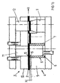
- Fig. 1a to 1d a simplified schematic representation of the sequence of the method according to the invention.
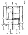
- Fig. 2 a sectional view of the design of the connecting portion between fine blank and material strips on the one hand and the design of die insert and cutting punch on the other hand and
- fine blanking parts 1 are to be produced from a strip of material 2.
- the Fig. 1a shows the device according to the invention with inserted strips of material 2 in the open state of the upper tool part 3 and lower tool part 4.
- the lower tool part 4 includes a cutting plate 5, which has a receiving space 6 for receiving a die insert 7.
- the Matrizenrus 7 is in the Fig. 1a shown as a simple tubular insert, but may also have other more complicated shapes. At its periphery of the die insert 7 is held for example by a screw, not shown in the cutting plate 5 under uniform bias, so that the forces occurring during cutting can be safely absorbed by die insert 7. The Matrizenrus 7 is thus removed from the receiving space 6 of the cutting plate 5 and can be reground accordingly if necessary.
- the height loss of the die insert 7 compensated as a result of regrinding. It documents 8 are kept at different thicknesses, so that depending on the size of the regrinding different height losses can be compensated and the die insert 7 reaches the original height again.
- the die insert 7 has a height offset H, so that the die insert 7 is significantly above the level of the cutting plate 5.
- This height offset H is dimensioned such that it corresponds approximately to the material thickness of the material strip 2.
- the upper tool part 3 and lower tool part 4 of the device according to the invention are opened so far that the imported material strip with the tailed fine cutting part 1 has sufficient space in the direction R of the material strip 2.
- a chute 9 for discharging the fine cutting parts 1 is arranged approximately vertically downwards to the direction R of the material strip 2.
- the die insert 7 is a punch 11 in the upper tool part 3 for cutting the fine blanking part 1 from the strip of material 2 and the chute 9 associated with an ejector 12.
- the upper tool part 3 includes a press or guide plate 10 in which at least one cutting punch 11 and at least one ejector 12 are guided.
- Fig. 1b shows the closed upper tool part 3 and lower tool part 4 with between die insert 7 and
- the clamping plate is clamped around the cutting geometry, so that the fine cutting specific clamping forces are concentrated on a narrow range. This supports the production of smooth-cut separating surfaces on the fineblanking part 1.
- lubrication pockets arranged in the cutting plate can be dispensed with and the lubricant supply on the material strip is available exclusively for the fineblanking process.
- Fig. 1c shows the step of the method according to the invention, in which the cutting punch 5 has performed an incomplete complete cut in the strip of material 2 and the fine part cutting part 1 is cut to about 80 to 90% of its circumference.
- Fig. 2 Reference is made, in which the fine blanking part 1 remains connected to, for example, a narrow connecting portion 14 with the material strip 2 cohesively after the cut.
- the incomplete complete cut is achieved by a corresponding preparation of the cutting edges 15 of die insert 7 and / or cutting punch 11 in conjunction with the kinematics of the fine blanking press used, which always moves independently of the thickness variations of the material strip in the same vertical position of the cutting edges of die insert 7 and cutting punch 11 , reached.
- the cutting edge 15 of the die insert 7 can be broken, for example, along its edge profile by one or more chamfers 16.
- the width and / or length and / or inclination of these bevels vary. This is aimed according to the size, geometry and after their distribution on the die insert 7 and / or cutting punch 11 and the thickness and quality of the material strip and the allowable shape tolerances radially and axially at the connection points, the fine blanking part 1, which by the dimensions h and i am Die insert 7 and the dimensions 1 and k is illustrated on the cutting punch. This also applies to the Einschertiefe T of the cutting punch 11 in the die insert. 7
- the ejector 12 of the demolding stage has separated the connecting parts 14 between the fineblank 1 and strips of material 2 shearing force and fineblanking part 1 is discharged through the chute 9 perpendicular to the direction R of the strip of material 2 down.
- the connecting parts 14 are broken by the ejector 12 largely free of damage.
- the connecting parts 14 are distributed on the circumference of the fineblanking part 1 that they do not lie on the functional surfaces of the fineblanking part.
- the strip of material 1 forms after the cutting process with the tailed fine cutting part 1 a composite that can be transported without any relative movement in the vertical direction with open inventive device in the direction R to Entformungscut, because by the relative to the die insert 7 deeper placed cutting plate 5 sufficient space which is about the thickness of the strip of material 2 downwardly protruding fine cutting 1 is present.
- This is associated with the very great advantage that the necessary opening path at the device according to the invention can be kept so small that the cycle numbers can be massively increased. This allows the use of high speed presses.
Claims (10)
- Procédé pour fabriquer des pièces de découpe fine sur un outil de découpe fine, dans lequel une bande de matériau est coincée entre deux parties d'outil respectivement entre une plaque de compression ou de guidage supérieure et une plaque de découpe inférieure ainsi qu'entre un poinçon de découpe supérieur et un poinçon de découpe inférieur et la découpe s'effectue en interaction avec le poinçon de découpe supérieur et le poinçon de découpe inférieur, la découpe étant effectuée sous la forme d'une coupe complète non achevée le long du pourtour de la partie de découpage fin avec une arête de coupe formée spécialement du poinçon de découpe et/ou de la plaque de découpe, de telle sorte que la pièce de découpe fine reste d'abord attachée par complémentarité de matière à des parties de liaison partielles sur la bande de matériau à peu près sur son niveau supérieur ou son niveau inférieur dans une position de hauteur par rapport à la bande de matériau et est déplacée ensuite conjointement avec la bande de matériau dans le sens de marche de la bande jusqu'une étape de déformation consécutive, dans lequel les parties de liaison partielles sont séparées les unes des autres de la bande de matériau sans force de cisaillement sans un refoulement, caractérisé en ce qu'on utilise pour la découpe un insert de matrice pouvant être inséré dans un logement de la plaque de découpe et un poinçon de découpe attribué à l'insert de matrice avec des chanfreins formés partiellement le long de ses arêtes de coupe, la pièce de découpe fine et la bande de matériau étant déformées par une cassure sans force de cisaillement perpendiculairement au sens de marche de la bande de matériau vers le bas, la partie de découpe fine déformée étant évacuée par un puits de chute dans la plaque de découpe.
- Procédé selon la revendication 1, caractérisé en ce que la pièce de découpe fine est découpée pour environ 80 à 90 % de son pourtour complètement dans la bande de matériau.
- Procédé selon les revendications 1 et 2, caractérisé en ce que la pièce de découpe fine est maintenue après la coupe complète inachevée sur la bande de matériau par au moins une, en particulier deux ou plusieurs parties de liaison.
- Procédé selon la revendication 1, caractérisé en ce que l'insert de matrice peut être utilisé plusieurs fois par une rectification côté avant, la perte en hauteur ou la perte de matériau de l'insert de matrice, résultant de la rectification, étant composée par une ou plusieurs rondelles insérées dans le logement de la plaque de découpe.
- Procédé selon la revendication 1, caractérisé en ce que l'insert de matrice est précontraint de façon uniforme le long de son pourtour par une forme adaptée à la géométrie de la pièce de découpe fine.
- Procédé selon les revendications 1 à 5, caractérisé en ce que le serrage de la bande de matériau entre la partie d'outil supérieure et la partie d'outil inférieure s'effectue uniquement par l'insert de matrice.
- Dispositif pour fabriquer des pièces de découpe fine dans une bande de matériau, comprenant au moins une plaque de découpe et un poinçon de découpe pour le découpage de la pièce de découpe fine dans une bande de matériau, caractérisé en ce qu'un insert de matrice (7) maintenu par adhérence sous pré-tension uniforme est disposé dans un espace de logement (6) de la plaque de découpe (5), insert auquel est attribué le poinçon de découpe (12), les arêtes de coupe (15) de l'insert de matrice (7) et/ou du poinçon de découpe (12) étant interrompues par un chanfrein (16) formé partiellement pour le découpage incomplet de la partie de découpe fine (1) dans la bande de matériau (2), de telle sorte que la partie de découpe fine (1) et la bande de matériau (2) sont reliées par des parties de liaison (14) partielles par complémentarité de matière après la découpe et en ce que l'insert de matrice (7) présente par rapport à la plaque de découpe (5) un décalage en hauteur (H) pour le serrage partiel de la bande de matériau (2) sur une plaque de compression ou une plaque de guidage (10) et en ce que dans la plaque de découpe (5) est prévu un puits de chute (9) pour l'évacuation de la partie de découpe fine séparée de la bande de matériau par une cassure sans force de cisaillement, perpendiculairement vers le bas par rapport au sens de marche de la bande de matériau.
- Dispositif selon la revendication 7, caractérisé en ce que les chanfreins (16) présentent une longueur et/ou une largeur et/ou une inclinaison différente(s).
- Dispositif selon la revendication 7, caractérisé en ce que l'insert de matrice (7) est amovible.
- Dispositif selon la revendication 7, caractérisé en ce qu'un ou plusieurs rondelles (8), disposées dans l'espace de logement (6) au-dessous de l'insert de matrice (7), d'épaisseur différente, sont prévues pour la compensation de la perte de matériau ou de la perte en hauteur causée lors de la rectification de l'insert de matrice.
Priority Applications (7)
| Application Number | Priority Date | Filing Date | Title |
|---|---|---|---|
| AT08012011T ATE524251T1 (de) | 2008-07-03 | 2008-07-03 | Verfahren und vorrichtung zum herstellen von feinschneidteilen aus einem materialstreifen |
| EP20080012011 EP2140954B1 (fr) | 2008-07-03 | 2008-07-03 | Procédé et dispositif de fabrication de parties coupantes fines d'une bande de matériau |
| PCT/EP2009/004364 WO2010000389A1 (fr) | 2008-07-03 | 2009-06-17 | Procédé et dispositif pour la production de pièces découpées de précision à partir d'une bande de matériau |
| JP2011515166A JP5698125B2 (ja) | 2008-07-03 | 2009-06-17 | 帯状材料から精密打ち抜き部品を製作する方法と装置 |
| EP20090772089 EP2303488B1 (fr) | 2008-07-03 | 2009-06-17 | Procédé et dispositif pour la production de pièces découpées de précision à partir d'une bande de matériau |
| AT09772089T ATE544541T1 (de) | 2008-07-03 | 2009-06-17 | Verfahren und vorrichtung zum herstellen von feinschneidteilen aus einem materialstreifen |
| US12/977,733 US8910549B2 (en) | 2008-07-03 | 2010-12-23 | Method and device for producing precision blankings from a material strip |
Applications Claiming Priority (1)
| Application Number | Priority Date | Filing Date | Title |
|---|---|---|---|
| EP20080012011 EP2140954B1 (fr) | 2008-07-03 | 2008-07-03 | Procédé et dispositif de fabrication de parties coupantes fines d'une bande de matériau |
Publications (2)
| Publication Number | Publication Date |
|---|---|
| EP2140954A1 EP2140954A1 (fr) | 2010-01-06 |
| EP2140954B1 true EP2140954B1 (fr) | 2011-09-14 |
Family
ID=39884537
Family Applications (2)
| Application Number | Title | Priority Date | Filing Date |
|---|---|---|---|
| EP20080012011 Not-in-force EP2140954B1 (fr) | 2008-07-03 | 2008-07-03 | Procédé et dispositif de fabrication de parties coupantes fines d'une bande de matériau |
| EP20090772089 Active EP2303488B1 (fr) | 2008-07-03 | 2009-06-17 | Procédé et dispositif pour la production de pièces découpées de précision à partir d'une bande de matériau |
Family Applications After (1)
| Application Number | Title | Priority Date | Filing Date |
|---|---|---|---|
| EP20090772089 Active EP2303488B1 (fr) | 2008-07-03 | 2009-06-17 | Procédé et dispositif pour la production de pièces découpées de précision à partir d'une bande de matériau |
Country Status (5)
| Country | Link |
|---|---|
| US (1) | US8910549B2 (fr) |
| EP (2) | EP2140954B1 (fr) |
| JP (1) | JP5698125B2 (fr) |
| AT (2) | ATE524251T1 (fr) |
| WO (1) | WO2010000389A1 (fr) |
Families Citing this family (19)
| Publication number | Priority date | Publication date | Assignee | Title |
|---|---|---|---|---|
| DE102011117023A1 (de) | 2011-10-27 | 2013-05-02 | Von Ardenne Anlagentechnik Gmbh | Beschichtungsvorrichtung und Verfahren zur Herstellung von organischen Schichten |
| EP2608299B1 (fr) * | 2011-12-22 | 2014-04-09 | Feintool Intellectual Property AG | Dispositif et procédé de fabrication de plaques bipolaires métalliques |
| CN102806264B (zh) * | 2012-08-09 | 2015-01-14 | 河南星光机械制造有限公司 | 一种双向精冲模具及双向精冲零件加工方法 |
| DE102014000299B3 (de) * | 2014-01-15 | 2015-07-16 | Rixen Wolfgang | Verfahren zur Erzeugung von Durchgängen in einem metallischen Körper mittels Hochgeschwindigkeitsscherschneiden sowie dessen Verwendung |
| JP6567292B2 (ja) * | 2014-03-17 | 2019-08-28 | 株式会社東亜鍛工所 | 孔を有する金属板の製造方法、周設孔付外歯歯車の製造方法及び金属板の製造方法 |
| JP6531114B2 (ja) * | 2014-12-18 | 2019-06-12 | 黒田精工株式会社 | 順送り金型装置用の逆押え装置及びこれを備えた順送り金型装置 |
| CN104959447B (zh) * | 2015-07-14 | 2017-03-01 | 武汉理工大学 | 一种偏载主动平衡精冲模具结构 |
| CN105290225A (zh) * | 2015-11-20 | 2016-02-03 | 重庆庆建机械配件有限公司 | 一种油门组合活动块落料冲孔模具 |
| CN106025769B (zh) * | 2016-07-27 | 2018-09-11 | 广东欧珀移动通信有限公司 | 电源适配器、移动终端及电源接口的制造方法 |
| CN106111801A (zh) * | 2016-08-31 | 2016-11-16 | 成都宏明双新科技股份有限公司 | 一种异形壳体拉深成型精密级进模 |
| CN107377767A (zh) * | 2017-08-23 | 2017-11-24 | 中山市创智智能科技有限公司 | Usb弹片加工模具 |
| JP7116477B2 (ja) * | 2018-08-07 | 2022-08-10 | 株式会社フロンティア | 抜き落とし加工装置及び抜き落とし加工方法 |
| CN112004620B (zh) * | 2018-10-31 | 2021-12-21 | 竹内忍 | 进行板材加工的加工装置及加工方法 |
| JP7263887B2 (ja) * | 2019-03-29 | 2023-04-25 | 株式会社アイシン | プレス加工装置 |
| DE102020107890A1 (de) | 2020-03-23 | 2021-09-23 | William Prym Gmbh & Co. Kg | Verfahren zur Herstellung eines Bauteils mit glatten Schnittflächen, insbesondere in einem Folgeverbundwerkzeug |
| CN111451360A (zh) * | 2020-04-07 | 2020-07-28 | 汤强兵 | 一种垫片冲压模具 |
| CN112692159B (zh) * | 2020-12-08 | 2023-01-24 | 倍升互联(北京)科技有限公司 | 一种cpu散热器用散热片自冲孔设备 |
| US20220219216A1 (en) * | 2021-01-14 | 2022-07-14 | Frontier Co., Ltd. | Stamping apparatus, method of stamping and stamping mold |
| CN117380832B (zh) * | 2023-12-11 | 2024-02-20 | 常州惠武精密机械有限公司 | 一种具有定位功能的喷丝板加工用冲孔机 |
Family Cites Families (39)
| Publication number | Priority date | Publication date | Assignee | Title |
|---|---|---|---|---|
| US2419862A (en) * | 1944-04-29 | 1947-04-29 | George F Wales | Method of and apparatus for punching by transfer means |
| US3232156A (en) * | 1963-12-26 | 1966-02-01 | Harrington & King Perforating | Multiple step perforating of sheet metal |
| CH531377A (de) * | 1968-04-11 | 1972-12-15 | Kondo Kazuyoshi | Schneidverfahren und Schnittwerkzeug zur Durchführung desselben |
| BE758810A (fr) * | 1969-11-15 | 1971-04-16 | Kondo Kazuyoshi | Procede de cisaillement de precision |
| US3712163A (en) * | 1970-06-15 | 1973-01-23 | Vinson Ind Inc | Shuttle press |
| IT972789B (it) * | 1972-12-22 | 1974-05-31 | Ibm Spa | Procedimento e dispositivi di tranciatura senza bave |
| US4078413A (en) * | 1973-07-30 | 1978-03-14 | Owens-Corning Fiberglas Corporation | Apparatus for producing fibers from heat-softenable materials |
| JPS53113259A (en) * | 1977-03-15 | 1978-10-03 | Takagi Mfg | Link plate manufacturing process of chain |
| US4141264A (en) * | 1977-06-02 | 1979-02-27 | Unipunch Products, Inc. | Adjustable high speed punch |
| JPS587371B2 (ja) * | 1977-07-11 | 1983-02-09 | 富士電機株式会社 | 薄板のエンボス成形方法 |
| DE2748228C2 (de) | 1977-10-27 | 1992-11-19 | Siemens AG, 1000 Berlin und 8000 München | Verfahren zum fortlaufenden Transport von durch einen Stanzstempel ausgestanzten einzelnen Stanzteilen für elektrische Geräte zu einer Stapelvorrichtung und Vorrichtung zur Durchführung des Verfahrens |
| JPS56134026A (en) * | 1980-03-25 | 1981-10-20 | Tsubakimoto Chain Co | Blanking method |
| US4477537A (en) * | 1982-09-23 | 1984-10-16 | Blase Tool And Manufacturing Co., Inc. | Method for producing burr-free blanks and the blanks produced thereby |
| US4610185A (en) * | 1984-04-26 | 1986-09-09 | France Daniel E | Rotatable master die set and quick change unit die system |
| JPH0464420U (fr) * | 1990-04-20 | 1992-06-02 | ||
| US5105696A (en) * | 1990-12-10 | 1992-04-21 | Jacobson Mfg. Co., Inc. | Method and apparatus for punching a cross hole |
| US5320013A (en) * | 1991-06-20 | 1994-06-14 | Fuji Electric Co., Ltd. | Method of blanking metal foil on piezoelectric actuator operated press, and die sets for practicing the method |
| US5163223A (en) * | 1991-08-21 | 1992-11-17 | Custom Stamping, Inc. | Process for making an electrical connector pin having fully rounded contact surfaces |
| US5442947A (en) * | 1993-03-12 | 1995-08-22 | Stodd; Ralph P. | Tooling apparatus and method for high speed production of drawn metal cup-like articles |
| JPH0973760A (ja) * | 1995-09-07 | 1997-03-18 | Sony Corp | プレート原反の打抜方法とテープカセットのベースプレート |
| US6163949A (en) * | 1996-06-05 | 2000-12-26 | L.H. Carbide Corporation | Method for manufacturing long, slender lamina stack from nonuniform laminae |
| US5881611A (en) * | 1997-01-07 | 1999-03-16 | Serigraph, Inc. | Punch button and process |
| JP3619364B2 (ja) * | 1998-03-20 | 2005-02-09 | 本田技研工業株式会社 | ファインブランキング方法およびファインブランキング装置 |
| JPH11309522A (ja) * | 1998-04-24 | 1999-11-09 | Honda Motor Co Ltd | 板材の打ち抜き加工方法 |
| JP2000246365A (ja) * | 1999-03-01 | 2000-09-12 | Nissan Motor Co Ltd | 順送り打ち抜き加工方法およびその装置 |
| JP2000271671A (ja) * | 1999-03-26 | 2000-10-03 | Matsushita Electric Ind Co Ltd | 金型セレクター |
| JP3497122B2 (ja) * | 2000-08-01 | 2004-02-16 | 株式会社ヤマナカゴーキン | 打抜き装置 |
| JP3864108B2 (ja) * | 2002-04-08 | 2006-12-27 | 松下電器産業株式会社 | プレス部品の加工方法と加工装置 |
| JP2004255454A (ja) * | 2003-02-27 | 2004-09-16 | Todo Kogyo Kk | 精密加工プレス用金型及びそれを用いた加工方法 |
| JP4295036B2 (ja) * | 2003-07-08 | 2009-07-15 | 本田技研工業株式会社 | 無段変速機用ベルトのエレメントの打抜き成形装置 |
| JP2005324236A (ja) * | 2004-05-14 | 2005-11-24 | Ricoh Co Ltd | 半抜き加工用パンチ、及び、プレス型、半抜き形状部材、及び画像形成装置 |
| DE102004032826B4 (de) * | 2004-07-06 | 2010-07-29 | Feintool International Management Ag | Verfahren zum Herstellen von Stanzteilen |
| EP1784766B1 (fr) * | 2004-08-10 | 2013-06-05 | Gemalto SA | Découplage entre des cartes |
| US7464575B2 (en) * | 2004-10-13 | 2008-12-16 | Nakamura Seisakusho Kabushikigaisha | Shearing method for thin plate |
| US7600312B2 (en) * | 2005-07-12 | 2009-10-13 | L.H. Carbide Corporation | Die assembly for manufacturing lamina stacks that include formed features |
| JP2009037980A (ja) * | 2007-08-03 | 2009-02-19 | Panasonic Corp | 電池缶および金属缶用ブランクとこれを用いた電池缶および金属缶の製造方法 |
| US8196498B2 (en) * | 2009-12-23 | 2012-06-12 | Wen-Pin Wang | Forming method for applying a continuous punching to a chain roller |
| DE112009005483T5 (de) * | 2009-12-26 | 2012-10-04 | Toyota Jidosha Kabushiki Kaisha | Elemente eines Riemens für ein stufenlos einstellbares Fahrzeuggetriebe und Verfahren des Herstellens der Elemente |
| JP5287917B2 (ja) * | 2011-03-25 | 2013-09-11 | 株式会社デンソー | 回転電機の回転子鉄心の製造方法 |
-
2008
- 2008-07-03 AT AT08012011T patent/ATE524251T1/de active
- 2008-07-03 EP EP20080012011 patent/EP2140954B1/fr not_active Not-in-force
-
2009
- 2009-06-17 WO PCT/EP2009/004364 patent/WO2010000389A1/fr active Application Filing
- 2009-06-17 AT AT09772089T patent/ATE544541T1/de active
- 2009-06-17 EP EP20090772089 patent/EP2303488B1/fr active Active
- 2009-06-17 JP JP2011515166A patent/JP5698125B2/ja active Active
-
2010
- 2010-12-23 US US12/977,733 patent/US8910549B2/en active Active
Also Published As
| Publication number | Publication date |
|---|---|
| ATE544541T1 (de) | 2012-02-15 |
| ATE524251T1 (de) | 2011-09-15 |
| US8910549B2 (en) | 2014-12-16 |
| EP2303488A1 (fr) | 2011-04-06 |
| JP2011526212A (ja) | 2011-10-06 |
| EP2303488B1 (fr) | 2012-02-08 |
| US20110132162A1 (en) | 2011-06-09 |
| WO2010000389A1 (fr) | 2010-01-07 |
| JP5698125B2 (ja) | 2015-04-08 |
| EP2140954A1 (fr) | 2010-01-06 |
Similar Documents
| Publication | Publication Date | Title |
|---|---|---|
| EP2140954B1 (fr) | Procédé et dispositif de fabrication de parties coupantes fines d'une bande de matériau | |
| EP1763413B1 (fr) | Procede et dispositif pour realiser des pieces estampees | |
| EP2886231B1 (fr) | Procédé de fabrication d'une pièce de carosserie formée par emboutissage | |
| EP1815922A1 (fr) | Procédé et outil pour le découpage fin de pièces ayant des petits rayons de coin et une profondeur fortement reduite en un seule étape | |
| DE1918780C2 (de) | Verfahren und Vorrichtung zum Feinschneiden von Werkstücken aus Blech | |
| DE19931932A1 (de) | Verfahren und System zum Anfasen und dafür verwendbare Presse | |
| DE112012000603T5 (de) | Vorrichtung und Verfahren zur Herstellung eines zusammengepressten Metallschrottblocks | |
| DE3331257A1 (de) | Vakuumziegelpresse | |
| EP2701861A1 (fr) | Procédé et dispositif de fabrication de pièces embouties sans bride | |
| EP1287918B1 (fr) | Procédé et dispositif pour la formation d'un coin limité sur trois côtés à partir d'un matériau en feuille plane | |
| DE69913646T2 (de) | Vorrichtung zum Hochdruckformen und Hochdruckschneiden | |
| EP3790681B1 (fr) | Dispositif et procédé de découpage d'une pièce | |
| EP2263812A1 (fr) | Procédé de fabrication de pièces découpées, notamment d'anneaux synchrones, de corps d'embrayage ou de disques d'embrayage | |
| DE19506067C1 (de) | Verfahren zum Ausschneiden eines Ausschnitts aus der Wandung eines als Hohlkörper ausgebildeten Bauteils und Vorrichtung zur Durchführung des Verfahrens | |
| DE202015101311U1 (de) | Bearbeitungsstation zum Bearbeiten von Endlos-Metallprofilen | |
| DE3312233C1 (de) | Stanzmaschine und Ausklinkmaschine | |
| WO2011134447A1 (fr) | Dispositif de moulage d'une pièce | |
| DE102006053223B3 (de) | Loch- und Durchzugsstempel | |
| DE19911125C1 (de) | Verfahren und Vorrichtung zum Trennen oder Lochen eines Werkstücks unter Einfluß eines unter Hochdruck stehenden Druckmediums | |
| EP3181257A2 (fr) | Outil d'emboutissage destiné à déformer des pièces | |
| DE10317015A1 (de) | Vorrichtung zum Stanzen von Werkstücken | |
| DE102006034304A1 (de) | Stanzpresse und Verfahren zum Betreiben einer Stanzpresse | |
| DE3108337A1 (de) | Strangpressmaschine und verfahren zum betrieb einer strangpressmaschine | |
| DE10014459A1 (de) | Verfahren zum Herstellen eines Körpers mit Domen durch Fließpressen | |
| DE19702445A1 (de) | Verfahren und Werkzeug zum Herstellen von Flachlagerschalen |
Legal Events
| Date | Code | Title | Description |
|---|---|---|---|
| PUAI | Public reference made under article 153(3) epc to a published international application that has entered the european phase |
Free format text: ORIGINAL CODE: 0009012 |
|
| AK | Designated contracting states |
Kind code of ref document: A1 Designated state(s): AT BE BG CH CY CZ DE DK EE ES FI FR GB GR HR HU IE IS IT LI LT LU LV MC MT NL NO PL PT RO SE SI SK TR |
|
| AX | Request for extension of the european patent |
Extension state: AL BA MK RS |
|
| 17P | Request for examination filed |
Effective date: 20100622 |
|
| 17Q | First examination report despatched |
Effective date: 20100719 |
|
| AKX | Designation fees paid |
Designated state(s): AT BE BG CH CY CZ DE DK EE ES FI FR GB GR HR HU IE IS IT LI LT LU LV MC MT NL NO PL PT RO SE SI SK TR |
|
| REG | Reference to a national code |
Ref country code: DE Ref legal event code: R079 Ref document number: 502008004844 Country of ref document: DE Free format text: PREVIOUS MAIN CLASS: B21D0028020000 Ipc: B21D0028100000 |
|
| GRAP | Despatch of communication of intention to grant a patent |
Free format text: ORIGINAL CODE: EPIDOSNIGR1 |
|
| RIC1 | Information provided on ipc code assigned before grant |
Ipc: B21D 28/16 20060101ALI20110405BHEP Ipc: B21D 45/00 20060101ALI20110405BHEP Ipc: B21D 28/10 20060101AFI20110405BHEP |
|
| GRAS | Grant fee paid |
Free format text: ORIGINAL CODE: EPIDOSNIGR3 |
|
| GRAA | (expected) grant |
Free format text: ORIGINAL CODE: 0009210 |
|
| AK | Designated contracting states |
Kind code of ref document: B1 Designated state(s): AT BE BG CH CY CZ DE DK EE ES FI FR GB GR HR HU IE IS IT LI LT LU LV MC MT NL NO PL PT RO SE SI SK TR |
|
| REG | Reference to a national code |
Ref country code: GB Ref legal event code: FG4D Free format text: NOT ENGLISH |
|
| REG | Reference to a national code |
Ref country code: CH Ref legal event code: EP |
|
| REG | Reference to a national code |
Ref country code: IE Ref legal event code: FG4D Free format text: LANGUAGE OF EP DOCUMENT: GERMAN |
|
| REG | Reference to a national code |
Ref country code: DE Ref legal event code: R096 Ref document number: 502008004844 Country of ref document: DE Effective date: 20111201 |
|
| REG | Reference to a national code |
Ref country code: NL Ref legal event code: VDEP Effective date: 20110914 |
|
| PG25 | Lapsed in a contracting state [announced via postgrant information from national office to epo] |
Ref country code: HR Free format text: LAPSE BECAUSE OF FAILURE TO SUBMIT A TRANSLATION OF THE DESCRIPTION OR TO PAY THE FEE WITHIN THE PRESCRIBED TIME-LIMIT Effective date: 20110914 Ref country code: NO Free format text: LAPSE BECAUSE OF FAILURE TO SUBMIT A TRANSLATION OF THE DESCRIPTION OR TO PAY THE FEE WITHIN THE PRESCRIBED TIME-LIMIT Effective date: 20111214 Ref country code: FI Free format text: LAPSE BECAUSE OF FAILURE TO SUBMIT A TRANSLATION OF THE DESCRIPTION OR TO PAY THE FEE WITHIN THE PRESCRIBED TIME-LIMIT Effective date: 20110914 Ref country code: LT Free format text: LAPSE BECAUSE OF FAILURE TO SUBMIT A TRANSLATION OF THE DESCRIPTION OR TO PAY THE FEE WITHIN THE PRESCRIBED TIME-LIMIT Effective date: 20110914 Ref country code: SE Free format text: LAPSE BECAUSE OF FAILURE TO SUBMIT A TRANSLATION OF THE DESCRIPTION OR TO PAY THE FEE WITHIN THE PRESCRIBED TIME-LIMIT Effective date: 20110914 |
|
| LTIE | Lt: invalidation of european patent or patent extension |
Effective date: 20110914 |
|
| PG25 | Lapsed in a contracting state [announced via postgrant information from national office to epo] |
Ref country code: CY Free format text: LAPSE BECAUSE OF FAILURE TO SUBMIT A TRANSLATION OF THE DESCRIPTION OR TO PAY THE FEE WITHIN THE PRESCRIBED TIME-LIMIT Effective date: 20110914 Ref country code: GR Free format text: LAPSE BECAUSE OF FAILURE TO SUBMIT A TRANSLATION OF THE DESCRIPTION OR TO PAY THE FEE WITHIN THE PRESCRIBED TIME-LIMIT Effective date: 20111215 Ref country code: SI Free format text: LAPSE BECAUSE OF FAILURE TO SUBMIT A TRANSLATION OF THE DESCRIPTION OR TO PAY THE FEE WITHIN THE PRESCRIBED TIME-LIMIT Effective date: 20110914 Ref country code: LV Free format text: LAPSE BECAUSE OF FAILURE TO SUBMIT A TRANSLATION OF THE DESCRIPTION OR TO PAY THE FEE WITHIN THE PRESCRIBED TIME-LIMIT Effective date: 20110914 |
|
| REG | Reference to a national code |
Ref country code: IE Ref legal event code: FD4D |
|
| PG25 | Lapsed in a contracting state [announced via postgrant information from national office to epo] |
Ref country code: IS Free format text: LAPSE BECAUSE OF FAILURE TO SUBMIT A TRANSLATION OF THE DESCRIPTION OR TO PAY THE FEE WITHIN THE PRESCRIBED TIME-LIMIT Effective date: 20120114 Ref country code: CZ Free format text: LAPSE BECAUSE OF FAILURE TO SUBMIT A TRANSLATION OF THE DESCRIPTION OR TO PAY THE FEE WITHIN THE PRESCRIBED TIME-LIMIT Effective date: 20110914 Ref country code: IE Free format text: LAPSE BECAUSE OF FAILURE TO SUBMIT A TRANSLATION OF THE DESCRIPTION OR TO PAY THE FEE WITHIN THE PRESCRIBED TIME-LIMIT Effective date: 20110914 Ref country code: SK Free format text: LAPSE BECAUSE OF FAILURE TO SUBMIT A TRANSLATION OF THE DESCRIPTION OR TO PAY THE FEE WITHIN THE PRESCRIBED TIME-LIMIT Effective date: 20110914 |
|
| PG25 | Lapsed in a contracting state [announced via postgrant information from national office to epo] |
Ref country code: EE Free format text: LAPSE BECAUSE OF FAILURE TO SUBMIT A TRANSLATION OF THE DESCRIPTION OR TO PAY THE FEE WITHIN THE PRESCRIBED TIME-LIMIT Effective date: 20110914 Ref country code: IT Free format text: LAPSE BECAUSE OF FAILURE TO SUBMIT A TRANSLATION OF THE DESCRIPTION OR TO PAY THE FEE WITHIN THE PRESCRIBED TIME-LIMIT Effective date: 20110914 Ref country code: NL Free format text: LAPSE BECAUSE OF FAILURE TO SUBMIT A TRANSLATION OF THE DESCRIPTION OR TO PAY THE FEE WITHIN THE PRESCRIBED TIME-LIMIT Effective date: 20110914 Ref country code: PL Free format text: LAPSE BECAUSE OF FAILURE TO SUBMIT A TRANSLATION OF THE DESCRIPTION OR TO PAY THE FEE WITHIN THE PRESCRIBED TIME-LIMIT Effective date: 20110914 Ref country code: PT Free format text: LAPSE BECAUSE OF FAILURE TO SUBMIT A TRANSLATION OF THE DESCRIPTION OR TO PAY THE FEE WITHIN THE PRESCRIBED TIME-LIMIT Effective date: 20120116 Ref country code: RO Free format text: LAPSE BECAUSE OF FAILURE TO SUBMIT A TRANSLATION OF THE DESCRIPTION OR TO PAY THE FEE WITHIN THE PRESCRIBED TIME-LIMIT Effective date: 20110914 |
|
| PLBE | No opposition filed within time limit |
Free format text: ORIGINAL CODE: 0009261 |
|
| STAA | Information on the status of an ep patent application or granted ep patent |
Free format text: STATUS: NO OPPOSITION FILED WITHIN TIME LIMIT |
|
| PG25 | Lapsed in a contracting state [announced via postgrant information from national office to epo] |
Ref country code: DK Free format text: LAPSE BECAUSE OF FAILURE TO SUBMIT A TRANSLATION OF THE DESCRIPTION OR TO PAY THE FEE WITHIN THE PRESCRIBED TIME-LIMIT Effective date: 20110914 |
|
| 26N | No opposition filed |
Effective date: 20120615 |
|
| REG | Reference to a national code |
Ref country code: DE Ref legal event code: R097 Ref document number: 502008004844 Country of ref document: DE Effective date: 20120615 |
|
| BERE | Be: lapsed |
Owner name: FEINTOOL INTELLECTUAL PROPERTY A.G. Effective date: 20120731 |
|
| PG25 | Lapsed in a contracting state [announced via postgrant information from national office to epo] |
Ref country code: MC Free format text: LAPSE BECAUSE OF NON-PAYMENT OF DUE FEES Effective date: 20120731 |
|
| REG | Reference to a national code |
Ref country code: CH Ref legal event code: PL |
|
| GBPC | Gb: european patent ceased through non-payment of renewal fee |
Effective date: 20120703 |
|
| REG | Reference to a national code |
Ref country code: FR Ref legal event code: ST Effective date: 20130329 |
|
| PG25 | Lapsed in a contracting state [announced via postgrant information from national office to epo] |
Ref country code: GB Free format text: LAPSE BECAUSE OF NON-PAYMENT OF DUE FEES Effective date: 20120703 Ref country code: LI Free format text: LAPSE BECAUSE OF NON-PAYMENT OF DUE FEES Effective date: 20120731 Ref country code: ES Free format text: LAPSE BECAUSE OF FAILURE TO SUBMIT A TRANSLATION OF THE DESCRIPTION OR TO PAY THE FEE WITHIN THE PRESCRIBED TIME-LIMIT Effective date: 20111225 Ref country code: FR Free format text: LAPSE BECAUSE OF NON-PAYMENT OF DUE FEES Effective date: 20120731 Ref country code: DE Free format text: LAPSE BECAUSE OF NON-PAYMENT OF DUE FEES Effective date: 20130201 Ref country code: CH Free format text: LAPSE BECAUSE OF NON-PAYMENT OF DUE FEES Effective date: 20120731 |
|
| PG25 | Lapsed in a contracting state [announced via postgrant information from national office to epo] |
Ref country code: BE Free format text: LAPSE BECAUSE OF NON-PAYMENT OF DUE FEES Effective date: 20120731 |
|
| PG25 | Lapsed in a contracting state [announced via postgrant information from national office to epo] |
Ref country code: BG Free format text: LAPSE BECAUSE OF FAILURE TO SUBMIT A TRANSLATION OF THE DESCRIPTION OR TO PAY THE FEE WITHIN THE PRESCRIBED TIME-LIMIT Effective date: 20111214 |
|
| PG25 | Lapsed in a contracting state [announced via postgrant information from national office to epo] |
Ref country code: MT Free format text: LAPSE BECAUSE OF FAILURE TO SUBMIT A TRANSLATION OF THE DESCRIPTION OR TO PAY THE FEE WITHIN THE PRESCRIBED TIME-LIMIT Effective date: 20110914 |
|
| REG | Reference to a national code |
Ref country code: DE Ref legal event code: R119 Ref document number: 502008004844 Country of ref document: DE Effective date: 20130201 |
|
| PG25 | Lapsed in a contracting state [announced via postgrant information from national office to epo] |
Ref country code: TR Free format text: LAPSE BECAUSE OF FAILURE TO SUBMIT A TRANSLATION OF THE DESCRIPTION OR TO PAY THE FEE WITHIN THE PRESCRIBED TIME-LIMIT Effective date: 20110914 |
|
| PG25 | Lapsed in a contracting state [announced via postgrant information from national office to epo] |
Ref country code: LU Free format text: LAPSE BECAUSE OF NON-PAYMENT OF DUE FEES Effective date: 20120703 |
|
| PG25 | Lapsed in a contracting state [announced via postgrant information from national office to epo] |
Ref country code: HU Free format text: LAPSE BECAUSE OF FAILURE TO SUBMIT A TRANSLATION OF THE DESCRIPTION OR TO PAY THE FEE WITHIN THE PRESCRIBED TIME-LIMIT Effective date: 20080703 |
|
| REG | Reference to a national code |
Ref country code: AT Ref legal event code: MM01 Ref document number: 524251 Country of ref document: AT Kind code of ref document: T Effective date: 20130703 |
|
| PG25 | Lapsed in a contracting state [announced via postgrant information from national office to epo] |
Ref country code: AT Free format text: LAPSE BECAUSE OF NON-PAYMENT OF DUE FEES Effective date: 20130703 |