EP2140954B1 - Method and device for manufacturing finely cut sections from a strip of material - Google Patents
Method and device for manufacturing finely cut sections from a strip of material Download PDFInfo
- Publication number
- EP2140954B1 EP2140954B1 EP20080012011 EP08012011A EP2140954B1 EP 2140954 B1 EP2140954 B1 EP 2140954B1 EP 20080012011 EP20080012011 EP 20080012011 EP 08012011 A EP08012011 A EP 08012011A EP 2140954 B1 EP2140954 B1 EP 2140954B1
- Authority
- EP
- European Patent Office
- Prior art keywords
- cutting
- die
- material strip
- fine blanking
- strip
- Prior art date
- Legal status (The legal status is an assumption and is not a legal conclusion. Google has not performed a legal analysis and makes no representation as to the accuracy of the status listed.)
- Not-in-force
Links
Images


Classifications
-
- B—PERFORMING OPERATIONS; TRANSPORTING
- B21—MECHANICAL METAL-WORKING WITHOUT ESSENTIALLY REMOVING MATERIAL; PUNCHING METAL
- B21D—WORKING OR PROCESSING OF SHEET METAL OR METAL TUBES, RODS OR PROFILES WITHOUT ESSENTIALLY REMOVING MATERIAL; PUNCHING METAL
- B21D28/00—Shaping by press-cutting; Perforating
- B21D28/02—Punching blanks or articles with or without obtaining scrap; Notching
- B21D28/10—Incompletely punching in such a manner that the parts are still coherent with the work
-
- B—PERFORMING OPERATIONS; TRANSPORTING
- B21—MECHANICAL METAL-WORKING WITHOUT ESSENTIALLY REMOVING MATERIAL; PUNCHING METAL
- B21D—WORKING OR PROCESSING OF SHEET METAL OR METAL TUBES, RODS OR PROFILES WITHOUT ESSENTIALLY REMOVING MATERIAL; PUNCHING METAL
- B21D28/00—Shaping by press-cutting; Perforating
- B21D28/02—Punching blanks or articles with or without obtaining scrap; Notching
- B21D28/16—Shoulder or burr prevention, e.g. fine-blanking
-
- B—PERFORMING OPERATIONS; TRANSPORTING
- B21—MECHANICAL METAL-WORKING WITHOUT ESSENTIALLY REMOVING MATERIAL; PUNCHING METAL
- B21D—WORKING OR PROCESSING OF SHEET METAL OR METAL TUBES, RODS OR PROFILES WITHOUT ESSENTIALLY REMOVING MATERIAL; PUNCHING METAL
- B21D45/00—Ejecting or stripping-off devices arranged in machines or tools dealt with in this subclass
- B21D45/003—Ejecting or stripping-off devices arranged in machines or tools dealt with in this subclass in punching machines or punching tools
-
- Y—GENERAL TAGGING OF NEW TECHNOLOGICAL DEVELOPMENTS; GENERAL TAGGING OF CROSS-SECTIONAL TECHNOLOGIES SPANNING OVER SEVERAL SECTIONS OF THE IPC; TECHNICAL SUBJECTS COVERED BY FORMER USPC CROSS-REFERENCE ART COLLECTIONS [XRACs] AND DIGESTS
- Y10—TECHNICAL SUBJECTS COVERED BY FORMER USPC
- Y10T—TECHNICAL SUBJECTS COVERED BY FORMER US CLASSIFICATION
- Y10T83/00—Cutting
- Y10T83/04—Processes
- Y10T83/0448—With subsequent handling [i.e., of product]
- Y10T83/0467—By separating products from each other
-
- Y—GENERAL TAGGING OF NEW TECHNOLOGICAL DEVELOPMENTS; GENERAL TAGGING OF CROSS-SECTIONAL TECHNOLOGIES SPANNING OVER SEVERAL SECTIONS OF THE IPC; TECHNICAL SUBJECTS COVERED BY FORMER USPC CROSS-REFERENCE ART COLLECTIONS [XRACs] AND DIGESTS
- Y10—TECHNICAL SUBJECTS COVERED BY FORMER USPC
- Y10T—TECHNICAL SUBJECTS COVERED BY FORMER US CLASSIFICATION
- Y10T83/00—Cutting
- Y10T83/04—Processes
- Y10T83/0524—Plural cutting steps
- Y10T83/0529—Blanking and cutting
-
- Y—GENERAL TAGGING OF NEW TECHNOLOGICAL DEVELOPMENTS; GENERAL TAGGING OF CROSS-SECTIONAL TECHNOLOGIES SPANNING OVER SEVERAL SECTIONS OF THE IPC; TECHNICAL SUBJECTS COVERED BY FORMER USPC CROSS-REFERENCE ART COLLECTIONS [XRACs] AND DIGESTS
- Y10—TECHNICAL SUBJECTS COVERED BY FORMER USPC
- Y10T—TECHNICAL SUBJECTS COVERED BY FORMER US CLASSIFICATION
- Y10T83/00—Cutting
- Y10T83/04—Processes
- Y10T83/06—Blanking
-
- Y—GENERAL TAGGING OF NEW TECHNOLOGICAL DEVELOPMENTS; GENERAL TAGGING OF CROSS-SECTIONAL TECHNOLOGIES SPANNING OVER SEVERAL SECTIONS OF THE IPC; TECHNICAL SUBJECTS COVERED BY FORMER USPC CROSS-REFERENCE ART COLLECTIONS [XRACs] AND DIGESTS
- Y10—TECHNICAL SUBJECTS COVERED BY FORMER USPC
- Y10T—TECHNICAL SUBJECTS COVERED BY FORMER US CLASSIFICATION
- Y10T83/00—Cutting
- Y10T83/202—With product handling means
- Y10T83/2074—Including means to divert one portion of product from another
- Y10T83/2079—Remaining or re-inserted product portion from base material
Definitions
- the invention relates to a method for producing fine blanking parts from a strip of material in a fine blanking tool, in which a strip of material is clamped between two tool parts or between an upper press or guide plate and a lower cutting plate and an upper and lower cutting punch and the cutting in cooperation with the upper wherein the cutting is carried out as an unfinished complete cut along the circumference of the fine blanking part with a specially shaped cutting edge of the cutting punch and / or cutting plate so that the fine blanking part at partial connecting parts on the material strip approximately at its upper or lower level in an altitude the material strip initially remains materially bonded and then moved together with the strip of material in the direction of the strip to a subsequent demolding stage (see JP 11309522 A ,
- the invention further relates to an apparatus for producing fine cutting parts of a strip of material, with at least one cutting plate and a cutting punch for cutting the fine cutting part of a strip of material. ).
- From the DE 10 2004 032 826 A1 is a method for producing stamped parts in a tool, in particular fine blanking tool, by means of at least one stamp, with which the stamped part is pushed out of a strip of material known.
- the punched part is pushed from the material strip of this after being pressed out to a discharge.
- the punch cooperates with a counter-holder in an insert when pressing out the stamped part, wherein the counter-holder the stamped part is lifted when opening the tool to the surface of the insert and the strip of material from the insert.
- the strip of material is lifted by the cutting plate at a defined distance which corresponds at least to the thickness of the stamped parts.
- the present invention seeks to improve a method and apparatus for producing fineblanked parts such that a vertical relative movement between strip of material and fineblanking part is completely avoided, reduces the necessary opening and closing of the device and a simple structure the device is a use on high-speed presses possible, the fineblanking parts suffer no damage to the functional surfaces.
- the solution according to the invention is characterized in that, for cutting, a die insert which can be inserted in a receptacle of the insert and a punch used with partially formed bevels along its cutting edges are used, and in the demolding step the partial bond parts are separated from the strip of material without pushing back
- the fine blanking part and the material strip are demolded downwards by a shear force-free breaking perpendicular to the running direction of the material strip, wherein the demoulded fine blanking part is removed through a chute in the cutting plate.
- the fine blanking part is cut to about 80 to 90% of its circumference completely from the strip of material.
- the fineblanking part is held on the material strip by at least one, in particular two or more, connecting part (s). These connection parts are to be arranged so that they do not come to lie in the area of the important functional surfaces of the fineblanking part during later breaking.
- connection points between the material strip and the fineblanking part are produced by the special shaping at the cutting edges of cutting punches and / or cutting plates in conjunction with the kinematics of the fineblanking press used, which are independent of the Thick variations of the material strip always moves in the same vertical position of the two decisive cutting edges.
- a recording of the insert at least one Matrizendon is inserted interchangeable and associated with a die insert opposite cutting punch with partially shaped chamfers along their cutting edges.
- the die insert is kept evenly biased along its circumference in the receptacle and projects beyond the base plate of the insert such that the die insert punctures the strip of material when closing the device on the punch, i. predetermined locations, can clamp without the base plate can engage.
- the ready-held enemy cutting oil not only distributes the areal pressure unintentionally and then is no longer available to a sufficient extent when cutting.
- the concentration of the fine cutting specific clamping forces on the die inserts continues to have the Advantage that the production of smooth cut surfaces on fineblanking part is supported.
- the demoulding process by breaking the connecting parts between the fineblank part and the material strip in the demoulding stage must ensure that no vertical shear forces are transmitted to the narrow connecting parts.
- the inventive device is simple and compact and has the great advantage that the required way to open and close the upper and lower part is significantly reduced. This is achieved in that in a receiving space of the cutting plate is arranged under a uniform bias force-locking die insert is associated with the cutting punch, wherein the cutting edges of the die insert and / or the cutting punch by a partially shaped barrel for incomplete cutting of Feinschneidteils from the strip of material are interrupted, such that the fine blanking part and the strip of material by partial connecting parts are materially interconnected after cutting, and that the die insert relative to the cutting plate has a vertical offset for partial clamping of the strip of material on a press or guide plate, and that in the cutting plate Downshaft for discharging the separated by a shear-free breaking off the strip of material fine cutting parts is provided vertically downwards to the direction of the strip of material.
- the special shaping of the cutting edges of die insert and / or punch consists of a partially shaped chamfer, which can vary in length and / or three and / or inclination and interrupts the cutting edge of Matrizenmony and / or cutting punch accordingly, so that the fine cutting part of the strip of material not is completely cut and remains firmly bonded to partial connecting parts on the material strip approximately at its upper or lower level in an altitude relative to the material strip.
- the space required for the transport of the composite of strips of material and fine blanking space within the interior of the device is achieved in that the die insert relative to the cutting plate has a height offset, which is dimensioned so that the required space for the material thickness downwardly protruding, however is still ensured on the strip of material fineblanking parts, so that the fineblanking parts can not be pushed back in the vertical direction or otherwise moved.
- the opposite to the cutting plate protruding die inserts allow for clamping the strip of material and a concentration of fine cutting specific clamping forces around the cutting geometry around, which provides the advantage that the quality of the interfaces on Feinschneidteil can be improved.
- the die insert is interchangeable and can also be used several times after regrinding.
- the one by the Regrind resulting height or material loss on Matrizenreheat can be compensated by placed in the receiving space under the die insert documents of different thickness very easily, allows flexible and cost-effective spare parts inventory with a high material utilization of Matrizenein algorithms.
- Another advantage is that the lubricant stored on the inlet side in lubricant pockets remains in the pockets when the material strip is clamped because only a selective clamping of the material strip around the cutting geometry takes place and the previously usual planar clamping of the material strip between upper and lower surfaces. and lower part of the device is eliminated.
- the inventive method and the device according to the invention are characterized by small opening and closing paths, so that high cycle rates and high output performance can be achieved, whereby the use of high-speed presses is made possible.
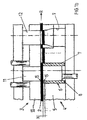
- Fig. 1a to 1d a simplified schematic representation of the sequence of the method according to the invention.
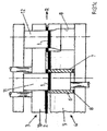
- Fig. 2 a sectional view of the design of the connecting portion between fine blank and material strips on the one hand and the design of die insert and cutting punch on the other hand and
- fine blanking parts 1 are to be produced from a strip of material 2.
- the Fig. 1a shows the device according to the invention with inserted strips of material 2 in the open state of the upper tool part 3 and lower tool part 4.
- the lower tool part 4 includes a cutting plate 5, which has a receiving space 6 for receiving a die insert 7.
- the Matrizenrus 7 is in the Fig. 1a shown as a simple tubular insert, but may also have other more complicated shapes. At its periphery of the die insert 7 is held for example by a screw, not shown in the cutting plate 5 under uniform bias, so that the forces occurring during cutting can be safely absorbed by die insert 7. The Matrizenrus 7 is thus removed from the receiving space 6 of the cutting plate 5 and can be reground accordingly if necessary.
- the height loss of the die insert 7 compensated as a result of regrinding. It documents 8 are kept at different thicknesses, so that depending on the size of the regrinding different height losses can be compensated and the die insert 7 reaches the original height again.
- the die insert 7 has a height offset H, so that the die insert 7 is significantly above the level of the cutting plate 5.
- This height offset H is dimensioned such that it corresponds approximately to the material thickness of the material strip 2.
- the upper tool part 3 and lower tool part 4 of the device according to the invention are opened so far that the imported material strip with the tailed fine cutting part 1 has sufficient space in the direction R of the material strip 2.
- a chute 9 for discharging the fine cutting parts 1 is arranged approximately vertically downwards to the direction R of the material strip 2.
- the die insert 7 is a punch 11 in the upper tool part 3 for cutting the fine blanking part 1 from the strip of material 2 and the chute 9 associated with an ejector 12.
- the upper tool part 3 includes a press or guide plate 10 in which at least one cutting punch 11 and at least one ejector 12 are guided.
- Fig. 1b shows the closed upper tool part 3 and lower tool part 4 with between die insert 7 and
- the clamping plate is clamped around the cutting geometry, so that the fine cutting specific clamping forces are concentrated on a narrow range. This supports the production of smooth-cut separating surfaces on the fineblanking part 1.
- lubrication pockets arranged in the cutting plate can be dispensed with and the lubricant supply on the material strip is available exclusively for the fineblanking process.
- Fig. 1c shows the step of the method according to the invention, in which the cutting punch 5 has performed an incomplete complete cut in the strip of material 2 and the fine part cutting part 1 is cut to about 80 to 90% of its circumference.
- Fig. 2 Reference is made, in which the fine blanking part 1 remains connected to, for example, a narrow connecting portion 14 with the material strip 2 cohesively after the cut.
- the incomplete complete cut is achieved by a corresponding preparation of the cutting edges 15 of die insert 7 and / or cutting punch 11 in conjunction with the kinematics of the fine blanking press used, which always moves independently of the thickness variations of the material strip in the same vertical position of the cutting edges of die insert 7 and cutting punch 11 , reached.
- the cutting edge 15 of the die insert 7 can be broken, for example, along its edge profile by one or more chamfers 16.
- the width and / or length and / or inclination of these bevels vary. This is aimed according to the size, geometry and after their distribution on the die insert 7 and / or cutting punch 11 and the thickness and quality of the material strip and the allowable shape tolerances radially and axially at the connection points, the fine blanking part 1, which by the dimensions h and i am Die insert 7 and the dimensions 1 and k is illustrated on the cutting punch. This also applies to the Einschertiefe T of the cutting punch 11 in the die insert. 7
- the ejector 12 of the demolding stage has separated the connecting parts 14 between the fineblank 1 and strips of material 2 shearing force and fineblanking part 1 is discharged through the chute 9 perpendicular to the direction R of the strip of material 2 down.
- the connecting parts 14 are broken by the ejector 12 largely free of damage.
- the connecting parts 14 are distributed on the circumference of the fineblanking part 1 that they do not lie on the functional surfaces of the fineblanking part.
- the strip of material 1 forms after the cutting process with the tailed fine cutting part 1 a composite that can be transported without any relative movement in the vertical direction with open inventive device in the direction R to Entformungscut, because by the relative to the die insert 7 deeper placed cutting plate 5 sufficient space which is about the thickness of the strip of material 2 downwardly protruding fine cutting 1 is present.
- This is associated with the very great advantage that the necessary opening path at the device according to the invention can be kept so small that the cycle numbers can be massively increased. This allows the use of high speed presses.
Abstract
Description
Die Erfindung betrifft ein Verfahren zum Herstellen von Feinschneidteilen aus einem Materialstreifen in einem Feinschneidwerkzeug, bei dem ein Materialstreifen zwischen zwei Werkzeugteilen bzw. zwischen einer oberen Pressoder Führungsplatte und einer unteren Schneidplatte sowie einem oberen und unteren Schneidstempel eingeklemmt wird und das Schneiden im Zusammenwirken mit den oberen und unteren Schneidstempel erfolgt wobei das Schneiden als ein unvollendeter Komplettschnitt entlang des Umfangs des Feinschneidteils mit einer speziell geformten Schneidkante von Schneidstempel und/oder Schneidplatte so durchgeführt wird, dass das Feinschneidteil an partiellen Verbindungspartien am Materialstreifen etwa an dessen oberen oder unteren Ebene in einer Höhenlage gegenüber dem Materialstreifen zunächst stoffschlüssig angebunden bleibt und dann zusammen mit dem Materialstreifen in Laufrichtung des Streifens bis zu einer nachfolgenden Entformungsstufe bewegt wird (siehe
Die Erfindung betrifft ferner eine Vorrichtung zum Herstellen von Feinschneidteilen aus einem Materialstreifen, mit mindestens einer Schneidplatte und einem Schneide stempel zum Ausschneiden des Feinschneidteils aus einem Materialstreifen.
).The invention further relates to an apparatus for producing fine cutting parts of a strip of material, with at least one cutting plate and a cutting punch for cutting the fine cutting part of a strip of material.
).
Aus der
Zwar vermeidet dieser bekannte Stand der Technik das für Feinschneidteile nachteilige Zurückdrücken des Feinschneidteils in den Materialstreifen, doch wird dieser Vorteil durch Relativbewegungen innerhalb des Werkzeuginnenraums senkrecht zur Laufrichtung des Materialstreifens erkauft, was ein vollständiges Öffnen des Werkzeugs erfordert und zugleich den Aufbau des Werkzeugs verkompliziert. Das vollständige Öffnen des Werkzeugs verlangt einen größeren Öffnungsweg, wodurch die Anzahl der Pressenhübe beschränkt wird. Dieser bekannte Stand der Technik kann daher nicht auf Hochgeschwindigkeitspressen eingesetzt werden.Although this known prior art avoids the fine blanking parts disadvantageous pushing back the fine blanking in the strip of material, but this advantage is purchased by relative movements within the tool cavity perpendicular to the direction of the strip of material, which requires a complete opening of the tool and at the same time complicates the structure of the tool. Full opening of the tool requires a larger opening travel, which limits the number of press strokes. Therefore, this prior art can not be used on high-speed presses.
Andere bekannte Lösungen führen die Stanzteile durch Vereinzelungsvorrichtungen (siehe
Bei diesem Stand der Technik liegt der Erfindung die Aufgabe zugrunde, ein Verfahren und eine Vorrichtung zum Herstellen von Feinschneidteilen derart zu verbessern, dass eine vertikale Relativbewegung zwischen Materialstreifen und Feinschneidteil völlig vermieden wird, der notwendige Öffnungs- und Schließweg der Vorrichtung reduziert und bei einfachem Aufbau der Vorrichtung ein Einsatz auf Hochgeschwindigkeitspressen möglich wird, wobei die Feinschneidteile keine Beschädigungen an den Funktionsflächen erleiden.In this prior art, the present invention seeks to improve a method and apparatus for producing fineblanked parts such that a vertical relative movement between strip of material and fineblanking part is completely avoided, reduces the necessary opening and closing of the device and a simple structure the device is a use on high-speed presses possible, the fineblanking parts suffer no damage to the functional surfaces.
Diese Aufgabe wird durch ein Verfahren der eingangs genannten Gattung mit den Merkmalen des Anspruchs 1 und durch eine Vorrichtung mit den Merkmalen des Anspruchs 9 gelöst.This object is achieved by a method of the type mentioned with the features of claim 1 and by a device having the features of
Vorteilhafte Ausgestaltungen des Verfahrens und der Vorrichtung sind den Unteransprüchen entnehmbar.Advantageous embodiments of the method and the device are the dependent claims.
Die erfindungsgemäße Lösung zeichnet sich dadurch aus, dass zum Schneiden ein in eine Aufnahme der Schneidplatte einsetzbarer Matrizeinsatz und ein dem Matrizeneinsatz zugeordneter Schneidstempel mit partiell ausgeformten Fasen entlang ihrer Schneidkanten verwendet werden, und dass in der Entformungsstufe die partiellen Verbindungspartien vom Materialstreifen ohne ein Zurückdrücken voneinander getrennt werden wobei das Feinschneidteil und der Materialstreifen durch ein scherkraftfreies Ausbrechen senkrecht zur Laufrichtung des Materialstreifens nach unten entformt werden, wobei das entformte Feinschneidteil durch einen Fallschacht in der Schneidplatte abgeführt wird.The solution according to the invention is characterized in that, for cutting, a die insert which can be inserted in a receptacle of the insert and a punch used with partially formed bevels along its cutting edges are used, and in the demolding step the partial bond parts are separated from the strip of material without pushing back The fine blanking part and the material strip are demolded downwards by a shear force-free breaking perpendicular to the running direction of the material strip, wherein the demoulded fine blanking part is removed through a chute in the cutting plate.
Nach dem erfindungsgemäßen Verfahren wird das Feinschneidteil zu etwa 80 bis 90% seines Umfanges komplett aus dem Materialstreifen ausgeschnitten. Es bestehen nur noch einzelne Verbindungsbereiche oder -punkte zwischen dem Feinschneidteil und dem Materialstreifen.
Das Feinschneidteil wird nach dem unvollendeten Komplettschnitt am Materialstreifen durch mindestens eine, insbesondere zwei oder mehrere, Verbindungspartie(n) gehalten. Diese Verbindungspartien sind dabei so anzuordnen, dass sie beim späteren Ausbrechen nicht in den Bereich der wichtigen Funktionsflächen des Feinschneidteils zu liegen kommen.According to the method of the invention, the fine blanking part is cut to about 80 to 90% of its circumference completely from the strip of material. There are only individual connection areas or points between the fine blank and the strip of material.
After the unfinished complete cut, the fineblanking part is held on the material strip by at least one, in particular two or more, connecting part (s). These connection parts are to be arranged so that they do not come to lie in the area of the important functional surfaces of the fineblanking part during later breaking.
Diese Verbindungspunkte zwischen Materialstreifen und Feinschneidteil entstehen durch die spezielle Formgebung an den Schneidkanten von Schneidstempel und/oder Schneidplatten in Verbindung mit der Kinematik der eingesetzten Feinschneidpresse, welche unabhängig von den Dickenschwankungen des Materialstreifens immer in dieselbe vertikale Position der beiden maßgebenden Schneidkanten fährt.These connection points between the material strip and the fineblanking part are produced by the special shaping at the cutting edges of cutting punches and / or cutting plates in conjunction with the kinematics of the fineblanking press used, which are independent of the Thick variations of the material strip always moves in the same vertical position of the two decisive cutting edges.
Tn eine Aufnahme der Schneidplatte ist mindestens ein Matrizeneinsatz austauschbar eingesetzt und ein dem Matrizeneinsatz gegenüberliegender Schneidstempel mit partiell ausgeformten Fasen entlang ihrer Schneidkanten zugeordnet.
Dies hat den außerordentlichen Vorteil, dass der Matrizeneinsatz durch ein stirnseitiges Nachschleifen mehrfach verwendbar ist, wobei der durch das Nachschleifen entstehende Höhen- bzw. Materialverlust des Matrizeneinsatzes durch eine oder mehrere in die Aufnahme eingesetzte Unterlagen leicht zu kompensieren ist, was wirtschaftliche Vorteile in der Ersatzbewirtschaftung mit sich bringt.Tn a recording of the insert at least one Matrizeneinsatz is inserted interchangeable and associated with a die insert opposite cutting punch with partially shaped chamfers along their cutting edges.
This has the extraordinary advantage that the Matrizeneinsatz is reusable by a front-side regrinding, the resulting by the regrinding height or material loss of Matrizeneinsatzes is easily compensated by one or more used in the recording records, which has economic benefits in the replacement management brings with it.
Der Matrizeneinsatz wird entlang seines Umfanges in der Aufnahme gleichmäßig vorgespannt gehalten und überragt die Grundplatte der Schneidplatte derart, dass der Matrizeneinsatz punktuell den Materialstreifen beim Schließen der Vorrichtung am Stempel, d.h. vorbestimmten Stellen, festklemmen kann, ohne dass die Grundplatte zum Eingriff gelangen kann. Mit anderen Worten es wird das bisher übliche großflächige Klemmen des Materialstreifens zwischen Ober- und Unterteil vermieden. Dies hat den weiteren Vorteil, dass das auf dem bereitgehaltene bereitgehaltene Feindschneidöl nicht nur das flächige Anpressen ungewollt verteilt wird und dann nicht mehr in ausreichendem Masse beim Schneiden zur Verfügung steht.The die insert is kept evenly biased along its circumference in the receptacle and projects beyond the base plate of the insert such that the die insert punctures the strip of material when closing the device on the punch, i. predetermined locations, can clamp without the base plate can engage. In other words, it is the hitherto conventional large-scale clamping of the material strip between the upper and lower part avoided. This has the further advantage that the ready-held enemy cutting oil not only distributes the areal pressure unintentionally and then is no longer available to a sufficient extent when cutting.
Die Konzentration der feinschneidspezifischen Klemmkräfte auf die Matrizeneinsätze hat weiterhin den Vorteil, dass die Erzeugung glattgeschnittener Trennflächen am Feinschneidteil unterstützt wird.The concentration of the fine cutting specific clamping forces on the die inserts continues to have the Advantage that the production of smooth cut surfaces on fineblanking part is supported.
Der Entformungsvorgang durch Ausbrechen der Verbindungspartien zwischen Feinschneidteil und Materialstreifen in der Entformungsstufe muss sicherstellen, dass keine vertikalen Scherkräfte auf die schmalen Verbindungspartien übertragen werden.The demoulding process by breaking the connecting parts between the fineblank part and the material strip in the demoulding stage must ensure that no vertical shear forces are transmitted to the narrow connecting parts.
Die erfindungsgemäße Vorrichtung ist einfach und kompakt aufgebaut und hat den großen Vorteil, dass der erforderliche Weg zum öffnen und Schließen von Ober- und Unterteil erheblich verringert wird. Dies wird dadurch erreicht, dass in einem Aufnahmeraum der Schneidplatte ein unter gleichmäßiger Vorspannung kraftsschlüssig gehaltener Matrizeneinsatz angeordnet ist, dem der Schneidstempel zugeordnet ist, wobei die Schneidkanten des Matrizeneinsatzes und/oder des Schneidstempels durch eine partiell ausgeformte Fass zum unvollständigen Ausschneiden des Feinschneidteils aus dem Materialstreifen unterbrochen sind, derart, dass das Feinschneidteil und der Materialstreifen durch partielle Verbindungspartien stoffschlüssig nach dem Schneiden miteinander verbunden sind, und dass der Matrizeneinsatz gegenüber der Schneidplatte einen Höhenversatz zum partiellen Klemmen des Materialstreifens an einer Press-oder Führungsplatte aufweist, und dass in der Schneidplatte ein Fallschacht zum Abführen der durch ein scherkraftfreies Ausbrechen vom Materialstreifen abgetrennten Feinschneidteile senkrecht nach unten zur Laufrichtung des Materialstreifens vorgesehen ist.The inventive device is simple and compact and has the great advantage that the required way to open and close the upper and lower part is significantly reduced. This is achieved in that in a receiving space of the cutting plate is arranged under a uniform bias force-locking die insert is associated with the cutting punch, wherein the cutting edges of the die insert and / or the cutting punch by a partially shaped barrel for incomplete cutting of Feinschneidteils from the strip of material are interrupted, such that the fine blanking part and the strip of material by partial connecting parts are materially interconnected after cutting, and that the die insert relative to the cutting plate has a vertical offset for partial clamping of the strip of material on a press or guide plate, and that in the cutting plate Downshaft for discharging the separated by a shear-free breaking off the strip of material fine cutting parts is provided vertically downwards to the direction of the strip of material.
Die spezielle Formgebung der Schneidkanten von Matrizeneinsatz und/oder Schneidstempel besteht aus einer partiell ausgeformten Fase, die in Länge und/Dreite und/oder Neigung variieren kann und die Schneidkante von Matrizeneinsatz und/oder Schneidstempel entsprechend unterbricht, so dass das Feinschneidteil aus dem Materialstreifen nicht vollständig ausgeschnitten wird und an partiellen Verbindungspartien am Materialstreifen etwa an dessen oberen oder unteren Ebene in einer Höhenlage gegenüber dem Materialstreifen stoffschlüssig angebunden bleibt.The special shaping of the cutting edges of die insert and / or punch consists of a partially shaped chamfer, which can vary in length and / or three and / or inclination and interrupts the cutting edge of Matrizeneinsatz and / or cutting punch accordingly, so that the fine cutting part of the strip of material not is completely cut and remains firmly bonded to partial connecting parts on the material strip approximately at its upper or lower level in an altitude relative to the material strip.
Der für den Transport des Verbundes aus Materialstreifen und Feinschneidteil erforderliche Freiraum innerhalb des Innenraums der Vorrichtung wird dadurch erreicht, dass der Matrizeneinsatz gegenüber der Schneidplatte einen Höhenversatz aufweist, der so bemessen ist, dass der erforderliche Platz für die um die Materialstärke nach unten herausstehenden, jedoch noch am Materialstreifen angebundenen Feinschneidteile sichergestellt ist, so dass die Feinschneidteile weder in vertikaler Richtung zurückgedrückt oder anderweitig bewegt werden können.The space required for the transport of the composite of strips of material and fine blanking space within the interior of the device is achieved in that the die insert relative to the cutting plate has a height offset, which is dimensioned so that the required space for the material thickness downwardly protruding, however is still ensured on the strip of material fineblanking parts, so that the fineblanking parts can not be pushed back in the vertical direction or otherwise moved.
Die gegenüber der Schneidplatte hervorstehenden Matrizeneinsätze ermöglichen beim Klemmen des Materialstreifens auch eine Konzentration der feinschneidspezifischen Klemmkräfte um die Schneidgeometrie herum, was den Vorteil erbringt, dass die Qualität der Trennflächen am Feinschneidteil verbessert werden kann.The opposite to the cutting plate protruding die inserts allow for clamping the strip of material and a concentration of fine cutting specific clamping forces around the cutting geometry around, which provides the advantage that the quality of the interfaces on Feinschneidteil can be improved.
Der Matrizeneinsatz ist austauschbar und nach einem Nachschleifen auch mehrfach verwendbar. Der durch das Nachschleifen entstehende Höhen- bzw. Materialverlust am Matrizeneinsatz lässt sich durch in den Aufnahmeraum unter den Matrizeneinsatz gelegte Unterlagen verschiedener Dicke sehr leicht ausgleichen, ermöglicht eine flexible und kostengünstige Ersatzteilhaltung mit einer hoher Materialausnutzung der Matrizeneinsätze.The die insert is interchangeable and can also be used several times after regrinding. The one by the Regrind resulting height or material loss on Matrizeneinsatz can be compensated by placed in the receiving space under the die insert documents of different thickness very easily, allows flexible and cost-effective spare parts inventory with a high material utilization of Matrizeneinsätze.
Als Vorteil ergibt sich des Weiteren, dass der einlaufseitig in Schmiertaschen bevorratete Schmierstoff für den Feinschneidvorgang beim Klemmen des Materialstreifens in den Taschen verbleibt, weil nur noch ein punktuelles Klemmen des Materialstreifens rund um die Schneidgeometrie erfolgt und das bisher übliche flächiges Klemmen des Materialstreifens zwischen Ober- und Unterteil der Vorrichtung entfällt.Another advantage is that the lubricant stored on the inlet side in lubricant pockets remains in the pockets when the material strip is clamped because only a selective clamping of the material strip around the cutting geometry takes place and the previously usual planar clamping of the material strip between upper and lower surfaces. and lower part of the device is eliminated.
Das erfindungsgemäße Verfahren und die erfindungsgemäße Vorrichtung zeichnen sich durch kleine Öffnung- und Schließwege aus, so dass hohe Taktzahlen und hohe Ausbringleistungen erreicht werden können, wodurch der Einsatz von Hochgeschwindigkeitspressen ermöglicht wird.The inventive method and the device according to the invention are characterized by small opening and closing paths, so that high cycle rates and high output performance can be achieved, whereby the use of high-speed presses is made possible.
Weitere Vorteile und Einzelheiten ergeben sich aus der nachfolgenden Beschreibung unter Bezugnahme auf die beigefügten Zeichnungen.Further advantages and details will become apparent from the following description with reference to the accompanying drawings.
Die Erfindung soll nachstehend an einem Ausführungsbeispiel näher erläutert werden.The invention will be explained in more detail below using an exemplary embodiment.
Es zeigen dieIt show the
Mit dem erfindungsgemäßen Verfahren sollen Feinschneidteile 1 aus einem Materialstreifen 2 hergestellt werden.With the method according to the invention, fine blanking parts 1 are to be produced from a strip of
Die
Der Matrizeneinsatz 7 ist in der
The Matrizeneinsatz 7 is in the
Gegenüber der Schneidplatte 5 weist der Matrizeneinsatz 7 einen Höhenversatz H auf, so dass der Matrizeneinsatz 7 deutlich über dem Niveau der Schneidplatte 5 liegt. Dieser Höhenversatz H ist so bemessen, dass er etwa der Materialstärke des Materialstreifens 2 entspricht. Das obere Werkzeugteil 3 und untere Werkzeugteil 4 der erfindungsgemäßen Vorrichtung sind soweit geöffnet, dass der eingeführte Materialstreifen mit dem angebundenen Feinschneidteil 1 ausreichend Platz in Laufrichtung R des Materialstreifens 2 besitzt.Compared to the cutting plate 5, the
In der unteren Schneidplatte 5 ist dem Matrizeneinsatz 7 ein Fallschacht 9 zum Abführen der Feinschneidteile 1 etwa senkrecht nach unten zur Laufrichtung R des Materialstreifens 2 nachgeordnet.In the lower cutting plate 5 is the die insert 7 a
Dem Matrizeneinsatz 7 ist ein Schneidstempel 11 im oberen Werkzeugteil 3 zum Ausschneiden des Feinschneidteils 1 aus dem Materialstreifen 2 und dem Fallschacht 9 ein Ausstosser 12 zugeordnet.
Zum oberen Werkzeugteil 3 gehört eine Press- oder Führungsplatte 10, in der mindestens ein Schneidstempel 11 und mindestens ein Ausstosser 12 geführt sind.The
The
Die
Der unvollständige Komplettschnitt wird durch eine entsprechende Präparation der Schneidkanten 15 von Matrizeneinsatz 7 und/oder Schneidstempel 11 in Verbindung mit der Kinematik der eingesetzten Feinschneidpresse, welche unabhängig von den Dickenschwankungen des Materialstreifens immer in die dieselbe vertikale Position der Schneidkanten von Matrizeneinsatz 7 und Schneidstempel 11 fährt, erreicht. Die Schneidkante 15 des Matrizeneinsatzes 7 kann beispielsweise entlang ihres Kantenverlaufs durch eine oder mehrere Fasen 16 gebrochen sein. Es gehört natürlich zur erfindungsgemäßen Lösung, wenn die Breite und/oder Länge und/oder Neigung dieser Fasen variieren. Dies richtet sich nach der Größe, Geometrie und nach ihrer Verteilung auf dem Matrizeneinsatz 7 und/oder Schneidstempel 11 sowie nach der Dicke und Qualität des Materialstreifens und nach den zulässigen Formtoleranzen radial und axial an den Anbindungspunkten, des Feinschneidteils 1, was durch die Maße h und i am Matrizeneinsatz 7 und die Maße 1 und k am Schneidstempel verdeutlicht ist. Das gilt auch für die Einschertiefe T des Schneidstempels 11 in den Matrizeneinsatz 7.The
The incomplete complete cut is achieved by a corresponding preparation of the cutting edges 15 of
In der
Der Materialstreifen 1 bildet nach dem Schneidvorgang mit dem angebundenen Feinschneidteil 1 einen Verbund, der ohne irgendeine Relativbewegung in vertikaler Richtung bei geöffneter erfindungsgemäßer Vorrichtung in Laufrichtung R bis zur Entformungsstufe transportiert werden kann, weil durch die gegenüber dem Matrizeneinsatz 7 tiefer gelegte Schneidplatte 5 ein ausreichender Platz der um etwa die Materialstärke des Materialstreifens 2 nach unten herausstehenden Feinschneidleile 1 vorhanden ist. Dies ist mit dem sehr großen Vorteil verbunden, dass der notwendige öffnungsweg bei der erfindungsgemäßen Vorrichtung so klein gehalten werden kann, dass die Taktzahlen massiv erhöht werden können. Dies ermöglicht, den Einsatz von Hochgeschwindigkeitspressen.The strip of material 1 forms after the cutting process with the tailed fine cutting part 1 a composite that can be transported without any relative movement in the vertical direction with open inventive device in the direction R to Entformungsstufe, because by the relative to the
Bezugszeichenliste
Claims (10)
- Method for producing fine blanking parts in a fine blanking tool, wherein a material strip is clamped between two tool parts respectively between an upper pressure pad or guiding plate and a lower cutting die as well as between an upper shearing punch and a lower shearing punch and the cutting is carried out in cooperation with the upper and lower shearing punches, wherein the cutting is realized as an incomplete compound die alongside the circumference of the fine blanking part with a specially formed cutting edge of the shearing punch and/or the cutting die in such a way, that the fine blanking part for the time being at partial connecting sections stays materially connected to the material strip with an elevation with regard to the material strip possibly at its upper or lower plane and then together with the material strip is moved in the moving direction of the strip until a following removal stage, characterized in that for cutting are used a die-plate inset, which can be positioned in a seating of the cutting die, and an allocated to the die-plate inset shearing punch with partially shaped bezels along their cutting edges, wherein the fine blanking part and the material strip are removed downwards perpendicular to the moving direction of the material strip by means of fracturing without shearing force, wherein the removed fine blanking part is removed through a hole in the cutting die.
- Method according to claim 1, characterized in that the fine blanking part up to 80 to 90 % of its circumference is completely cut out of the material strip.
- Method according to claims 1 and 2, characterized in that the fine blanking part after the incomplete compound die is hold at the material strip by at least one, in special cases by two or more, connection section(s).
- Method according to claim 1, characterized in that the die-plate inset due to resharpening the face side can be used repeatedly, wherein the loss of height respectively the loss of material of the die-plate inset created by the resharpening process is compensated by one or more spacers set into the seating of the cutting die.
- Method according to claim 1, characterized in that the die-plate inset alongside its circumference is uniformly prestressed due to the shape matched to the geometry of the fine blanking part.
- Method according to claims 1 to 5, characterized in that the clamping of the material strip between upper and lower tool parts is realized by solely the die-plate inset.
- Device for producing fine blanking parts from a material strip with at least one cutting die and one shearing punch for cutting the fine blanking part out of a material strip, characterized in that in a seating (6) of the cutting die (5) is located a die-plate (7) nonpositively hold under uniform prestress to which is allocated the shearing punch (12), wherein the cutting edges (15) of the die-plate inset (7) and/or the shearing punch (12) are interrupted by a partially shaped bezel (16) for incompletely cutting out the fine blanking part (1) of the material strip (2), in such a way, that the fine blanking part (1) and the material strip (2) are after the cutting process are materially connected by partial connecting sections (14) and that the die-plate inset (7) with regard to the cutting die (5) has an elevation (H) to partially clamp the material strip (2) at a pressure pad or guiding plate (10) and that in the cutting die (5) is provided a hole (9) for perpendicularly with regard to the moving direction of the material strip downwards removing the fine blanking part broken off the material strip without shearing force.
- Device according to claim 7, characterized in that the bezels (16) have a different length and/or width and/or angularity.
- Device according to claim 7, characterized in that the die-plate inset (7) is exchangeable.
- Device according to claim 7, characterized in that one or several positioned in the seating (6) under the die-plate inset (7) spacers (8) of different thickness are provided to compensate the material and height loss created by resharpening the die-plate inset.
Priority Applications (7)
| Application Number | Priority Date | Filing Date | Title |
|---|---|---|---|
| EP20080012011 EP2140954B1 (en) | 2008-07-03 | 2008-07-03 | Method and device for manufacturing finely cut sections from a strip of material |
| AT08012011T ATE524251T1 (en) | 2008-07-03 | 2008-07-03 | METHOD AND DEVICE FOR PRODUCING FINE BLANKED PARTS FROM A STRIP OF MATERIAL |
| JP2011515166A JP5698125B2 (en) | 2008-07-03 | 2009-06-17 | Method and apparatus for producing precision stamped parts from strip material |
| PCT/EP2009/004364 WO2010000389A1 (en) | 2008-07-03 | 2009-06-17 | Method and device for producing fine-blanked parts from a material strip |
| EP20090772089 EP2303488B1 (en) | 2008-07-03 | 2009-06-17 | Method and device for producing fine-blanked parts from a material strip |
| AT09772089T ATE544541T1 (en) | 2008-07-03 | 2009-06-17 | METHOD AND DEVICE FOR PRODUCING FINE BLANKED PARTS FROM A STRIP OF MATERIAL |
| US12/977,733 US8910549B2 (en) | 2008-07-03 | 2010-12-23 | Method and device for producing precision blankings from a material strip |
Applications Claiming Priority (1)
| Application Number | Priority Date | Filing Date | Title |
|---|---|---|---|
| EP20080012011 EP2140954B1 (en) | 2008-07-03 | 2008-07-03 | Method and device for manufacturing finely cut sections from a strip of material |
Publications (2)
| Publication Number | Publication Date |
|---|---|
| EP2140954A1 EP2140954A1 (en) | 2010-01-06 |
| EP2140954B1 true EP2140954B1 (en) | 2011-09-14 |
Family
ID=39884537
Family Applications (2)
| Application Number | Title | Priority Date | Filing Date |
|---|---|---|---|
| EP20080012011 Not-in-force EP2140954B1 (en) | 2008-07-03 | 2008-07-03 | Method and device for manufacturing finely cut sections from a strip of material |
| EP20090772089 Active EP2303488B1 (en) | 2008-07-03 | 2009-06-17 | Method and device for producing fine-blanked parts from a material strip |
Family Applications After (1)
| Application Number | Title | Priority Date | Filing Date |
|---|---|---|---|
| EP20090772089 Active EP2303488B1 (en) | 2008-07-03 | 2009-06-17 | Method and device for producing fine-blanked parts from a material strip |
Country Status (5)
| Country | Link |
|---|---|
| US (1) | US8910549B2 (en) |
| EP (2) | EP2140954B1 (en) |
| JP (1) | JP5698125B2 (en) |
| AT (2) | ATE524251T1 (en) |
| WO (1) | WO2010000389A1 (en) |
Families Citing this family (20)
| Publication number | Priority date | Publication date | Assignee | Title |
|---|---|---|---|---|
| DE102011117023A1 (en) | 2011-10-27 | 2013-05-02 | Von Ardenne Anlagentechnik Gmbh | Coating apparatus useful for producing organic layers on substrates, comprises container with region partially provided with openings that are permeable to coating gas and impermeable to non-gaseous coating material, and device for heating |
| EP2608299B1 (en) * | 2011-12-22 | 2014-04-09 | Feintool Intellectual Property AG | Device and method for manufacturing metallic bipolar panels |
| CN102806264B (en) * | 2012-08-09 | 2015-01-14 | 河南星光机械制造有限公司 | Two-way fine stamping die and two-way fine stamping part processing method |
| DE102014000299B3 (en) * | 2014-01-15 | 2015-07-16 | Rixen Wolfgang | Method for producing passages in a metallic body by means of high-speed shear cutting and its use |
| JP6567292B2 (en) * | 2014-03-17 | 2019-08-28 | 株式会社東亜鍛工所 | Method for manufacturing metal plate having holes, method for manufacturing external gear with peripheral hole, and method for manufacturing metal plate |
| WO2016098145A1 (en) * | 2014-12-18 | 2016-06-23 | 黒田精工株式会社 | Reverse holding device for forward feed molding device and forward feed molding device provided with same |
| CN104959447B (en) * | 2015-07-14 | 2017-03-01 | 武汉理工大学 | A kind of unbalance loading active balancing fine blanking die structure |
| CN105290225A (en) * | 2015-11-20 | 2016-02-03 | 重庆庆建机械配件有限公司 | Blanking-punching die of accelerator combined movable block |
| CN106025769B (en) | 2016-07-27 | 2018-09-11 | 广东欧珀移动通信有限公司 | The manufacturing method of power supply adaptor, mobile terminal and power interface |
| CN106111801A (en) * | 2016-08-31 | 2016-11-16 | 成都宏明双新科技股份有限公司 | A kind of special-shaped shell body drawing and forming precision progressive die |
| CN107377767A (en) * | 2017-08-23 | 2017-11-24 | 中山市创智智能科技有限公司 | USB shell fragment processing molds |
| JP7116477B2 (en) * | 2018-08-07 | 2022-08-10 | 株式会社フロンティア | Drop-off processing device and drop-off processing method |
| WO2020090872A1 (en) * | 2018-10-31 | 2020-05-07 | 竹内 忍 | Machining device for plate material machining, and machining method |
| JP7263887B2 (en) * | 2019-03-29 | 2023-04-25 | 株式会社アイシン | press machine |
| CN110560571A (en) * | 2019-10-14 | 2019-12-13 | 珠海格力精密模具有限公司 | Metal plate mould |
| DE102020107890A1 (en) | 2020-03-23 | 2021-09-23 | William Prym Gmbh & Co. Kg | Method for producing a component with smooth cut surfaces, in particular in a progressive tool |
| CN111451360A (en) * | 2020-04-07 | 2020-07-28 | 汤强兵 | Gasket stamping die |
| CN112692159B (en) * | 2020-12-08 | 2023-01-24 | 倍升互联(北京)科技有限公司 | Self-punching equipment for radiating fin of CPU radiator |
| US20220219216A1 (en) * | 2021-01-14 | 2022-07-14 | Frontier Co., Ltd. | Stamping apparatus, method of stamping and stamping mold |
| CN117380832B (en) * | 2023-12-11 | 2024-02-20 | 常州惠武精密机械有限公司 | Punching machine with positioning function for spinneret plate machining |
Family Cites Families (39)
| Publication number | Priority date | Publication date | Assignee | Title |
|---|---|---|---|---|
| US2419862A (en) * | 1944-04-29 | 1947-04-29 | George F Wales | Method of and apparatus for punching by transfer means |
| US3232156A (en) * | 1963-12-26 | 1966-02-01 | Harrington & King Perforating | Multiple step perforating of sheet metal |
| CH531377A (en) * | 1968-04-11 | 1972-12-15 | Kondo Kazuyoshi | Cutting method and cutting tool for carrying out the same |
| BE758810A (en) * | 1969-11-15 | 1971-04-16 | Kondo Kazuyoshi | PRECISION SHEAR PROCESS |
| US3712163A (en) * | 1970-06-15 | 1973-01-23 | Vinson Ind Inc | Shuttle press |
| IT972789B (en) * | 1972-12-22 | 1974-05-31 | Ibm Spa | PROCESS AND DEVICES FOR SHEARING WITHOUT BAVE |
| US4078413A (en) * | 1973-07-30 | 1978-03-14 | Owens-Corning Fiberglas Corporation | Apparatus for producing fibers from heat-softenable materials |
| JPS53113259A (en) * | 1977-03-15 | 1978-10-03 | Takagi Mfg | Link plate manufacturing process of chain |
| US4141264A (en) * | 1977-06-02 | 1979-02-27 | Unipunch Products, Inc. | Adjustable high speed punch |
| JPS587371B2 (en) * | 1977-07-11 | 1983-02-09 | 富士電機株式会社 | Embossing method for thin plates |
| DE2748228C2 (en) | 1977-10-27 | 1992-11-19 | Siemens AG, 1000 Berlin und 8000 München | Method for the continuous transport of individual punched parts for electrical devices punched out by a punch to a stacking device and device for carrying out the method |
| JPS56134026A (en) * | 1980-03-25 | 1981-10-20 | Tsubakimoto Chain Co | Blanking method |
| US4477537A (en) * | 1982-09-23 | 1984-10-16 | Blase Tool And Manufacturing Co., Inc. | Method for producing burr-free blanks and the blanks produced thereby |
| US4610185A (en) * | 1984-04-26 | 1986-09-09 | France Daniel E | Rotatable master die set and quick change unit die system |
| JPH0464420U (en) * | 1990-04-20 | 1992-06-02 | ||
| US5105696A (en) * | 1990-12-10 | 1992-04-21 | Jacobson Mfg. Co., Inc. | Method and apparatus for punching a cross hole |
| US5320013A (en) * | 1991-06-20 | 1994-06-14 | Fuji Electric Co., Ltd. | Method of blanking metal foil on piezoelectric actuator operated press, and die sets for practicing the method |
| US5163223A (en) * | 1991-08-21 | 1992-11-17 | Custom Stamping, Inc. | Process for making an electrical connector pin having fully rounded contact surfaces |
| US5442947A (en) * | 1993-03-12 | 1995-08-22 | Stodd; Ralph P. | Tooling apparatus and method for high speed production of drawn metal cup-like articles |
| JPH0973760A (en) * | 1995-09-07 | 1997-03-18 | Sony Corp | Method for blanking plate stock and base plate of tape cassette |
| US6163949A (en) * | 1996-06-05 | 2000-12-26 | L.H. Carbide Corporation | Method for manufacturing long, slender lamina stack from nonuniform laminae |
| US5881611A (en) * | 1997-01-07 | 1999-03-16 | Serigraph, Inc. | Punch button and process |
| JP3619364B2 (en) * | 1998-03-20 | 2005-02-09 | 本田技研工業株式会社 | Fine blanking method and fine blanking device |
| JPH11309522A (en) * | 1998-04-24 | 1999-11-09 | Honda Motor Co Ltd | Method for punching out plate material |
| JP2000246365A (en) * | 1999-03-01 | 2000-09-12 | Nissan Motor Co Ltd | Sequential transfer/punch processing method and device thereof |
| JP2000271671A (en) * | 1999-03-26 | 2000-10-03 | Matsushita Electric Ind Co Ltd | Die selector |
| JP3497122B2 (en) * | 2000-08-01 | 2004-02-16 | 株式会社ヤマナカゴーキン | Punching equipment |
| JP3864108B2 (en) * | 2002-04-08 | 2006-12-27 | 松下電器産業株式会社 | Press part processing method and processing equipment |
| JP2004255454A (en) * | 2003-02-27 | 2004-09-16 | Todo Kogyo Kk | Die for precision working press, and pressing method using the same |
| JP4295036B2 (en) * | 2003-07-08 | 2009-07-15 | 本田技研工業株式会社 | Punching device for belt element for continuously variable transmission |
| JP2005324236A (en) * | 2004-05-14 | 2005-11-24 | Ricoh Co Ltd | Punch and press die for half-blanking, member with half-blanked shape and image forming apparatus |
| DE102004032826B4 (en) * | 2004-07-06 | 2010-07-29 | Feintool International Management Ag | Method for producing stamped parts |
| WO2006016257A1 (en) * | 2004-08-10 | 2006-02-16 | Axalto Sa | Progressive unplugging multi-cards body |
| US7464575B2 (en) * | 2004-10-13 | 2008-12-16 | Nakamura Seisakusho Kabushikigaisha | Shearing method for thin plate |
| US7600312B2 (en) * | 2005-07-12 | 2009-10-13 | L.H. Carbide Corporation | Die assembly for manufacturing lamina stacks that include formed features |
| JP2009037980A (en) * | 2007-08-03 | 2009-02-19 | Panasonic Corp | Blank for battery can and metal can and manufacturing method for battery can and metal can using the same |
| US8196498B2 (en) * | 2009-12-23 | 2012-06-12 | Wen-Pin Wang | Forming method for applying a continuous punching to a chain roller |
| WO2011077582A1 (en) * | 2009-12-26 | 2011-06-30 | トヨタ自動車株式会社 | Element for belt for stepless transmission, and method of manufacturing same |
| JP5287917B2 (en) * | 2011-03-25 | 2013-09-11 | 株式会社デンソー | Manufacturing method of rotor core of rotating electrical machine |
-
2008
- 2008-07-03 AT AT08012011T patent/ATE524251T1/en active
- 2008-07-03 EP EP20080012011 patent/EP2140954B1/en not_active Not-in-force
-
2009
- 2009-06-17 JP JP2011515166A patent/JP5698125B2/en active Active
- 2009-06-17 AT AT09772089T patent/ATE544541T1/en active
- 2009-06-17 WO PCT/EP2009/004364 patent/WO2010000389A1/en active Application Filing
- 2009-06-17 EP EP20090772089 patent/EP2303488B1/en active Active
-
2010
- 2010-12-23 US US12/977,733 patent/US8910549B2/en active Active
Also Published As
| Publication number | Publication date |
|---|---|
| JP5698125B2 (en) | 2015-04-08 |
| JP2011526212A (en) | 2011-10-06 |
| US8910549B2 (en) | 2014-12-16 |
| EP2140954A1 (en) | 2010-01-06 |
| EP2303488B1 (en) | 2012-02-08 |
| ATE544541T1 (en) | 2012-02-15 |
| EP2303488A1 (en) | 2011-04-06 |
| ATE524251T1 (en) | 2011-09-15 |
| US20110132162A1 (en) | 2011-06-09 |
| WO2010000389A1 (en) | 2010-01-07 |
Similar Documents
| Publication | Publication Date | Title |
|---|---|---|
| EP2140954B1 (en) | Method and device for manufacturing finely cut sections from a strip of material | |
| EP1763413B1 (en) | Method and device for the production of stamped parts | |
| EP2886231B1 (en) | Method of manufacturing a formed portion of a car body | |
| EP1815922A1 (en) | Method of and tool for fine-cutting pieces with small edge radius and strongly reduced depth in a single step arrangement | |
| DE1918780C2 (en) | Method and device for fine blanking of sheet metal workpieces | |
| DE19931932A1 (en) | Chamfering routine with work feed handles sheet between top and spring-supported bottom tool as plungers in two-sided chamfer press. | |
| DE112012000603T5 (en) | Apparatus and method for producing a compressed metal scrap block | |
| DE3331257A1 (en) | VACUUM BRICK PRESS | |
| WO2012146601A1 (en) | Method and device for producing flangeless drawn parts | |
| DE69913646T2 (en) | Device for high pressure molding and high pressure cutting | |
| EP1287918B1 (en) | Method and device for forming a corner limited on three sides from a flat sheet material | |
| EP3790681B1 (en) | Device and method for the removal of a workpiece | |
| EP2263812A1 (en) | Method for producing stamped parts, in particular synchronous rings, coupling bodies or coupling discs | |
| DE19506067C1 (en) | Aperture cutter for pressure moulded items | |
| DE202015101311U1 (en) | Processing station for processing endless metal profiles | |
| DE3312233C1 (en) | Punching machine and notching machine | |
| WO2011134447A1 (en) | Device for shaping a workpiece | |
| DE102006053223B3 (en) | Sheet metal punch has centering tip surrounded by circular shoulder in close proximity to surplus metal ejector pins | |
| DE19911125C1 (en) | Workpiece cutting/perforation forms a pressure zone with a pressure medium on one side with a cutting edge and a spaced auxiliary cutting edge on the other workpiece side giving cut edges with low distortion and small flash height | |
| EP3181257A2 (en) | Drawing tool for forming workpieces | |
| DE10317015A1 (en) | Arrangement for stamping workpieces, has stamping blades arranged along stamping opening, ejection element movably guided relative to carrying element and pressure element above carrying element | |
| DE102006034304A1 (en) | Punching press and method for operating a punch press | |
| DE3108337A1 (en) | EXTRACTION MACHINE AND METHOD FOR OPERATING AN EXTRACTION MACHINE | |
| DE10014459A1 (en) | Method for producing cooling on cooling block via a press process through a matrix and with a shaped ejector to remove the block from the press | |
| DE19702445A1 (en) | Process and tool for manufacturing flat bearing shells |
Legal Events
| Date | Code | Title | Description |
|---|---|---|---|
| PUAI | Public reference made under article 153(3) epc to a published international application that has entered the european phase |
Free format text: ORIGINAL CODE: 0009012 |
|
| AK | Designated contracting states |
Kind code of ref document: A1 Designated state(s): AT BE BG CH CY CZ DE DK EE ES FI FR GB GR HR HU IE IS IT LI LT LU LV MC MT NL NO PL PT RO SE SI SK TR |
|
| AX | Request for extension of the european patent |
Extension state: AL BA MK RS |
|
| 17P | Request for examination filed |
Effective date: 20100622 |
|
| 17Q | First examination report despatched |
Effective date: 20100719 |
|
| AKX | Designation fees paid |
Designated state(s): AT BE BG CH CY CZ DE DK EE ES FI FR GB GR HR HU IE IS IT LI LT LU LV MC MT NL NO PL PT RO SE SI SK TR |
|
| REG | Reference to a national code |
Ref country code: DE Ref legal event code: R079 Ref document number: 502008004844 Country of ref document: DE Free format text: PREVIOUS MAIN CLASS: B21D0028020000 Ipc: B21D0028100000 |
|
| GRAP | Despatch of communication of intention to grant a patent |
Free format text: ORIGINAL CODE: EPIDOSNIGR1 |
|
| RIC1 | Information provided on ipc code assigned before grant |
Ipc: B21D 28/16 20060101ALI20110405BHEP Ipc: B21D 45/00 20060101ALI20110405BHEP Ipc: B21D 28/10 20060101AFI20110405BHEP |
|
| GRAS | Grant fee paid |
Free format text: ORIGINAL CODE: EPIDOSNIGR3 |
|
| GRAA | (expected) grant |
Free format text: ORIGINAL CODE: 0009210 |
|
| AK | Designated contracting states |
Kind code of ref document: B1 Designated state(s): AT BE BG CH CY CZ DE DK EE ES FI FR GB GR HR HU IE IS IT LI LT LU LV MC MT NL NO PL PT RO SE SI SK TR |
|
| REG | Reference to a national code |
Ref country code: GB Ref legal event code: FG4D Free format text: NOT ENGLISH |
|
| REG | Reference to a national code |
Ref country code: CH Ref legal event code: EP |
|
| REG | Reference to a national code |
Ref country code: IE Ref legal event code: FG4D Free format text: LANGUAGE OF EP DOCUMENT: GERMAN |
|
| REG | Reference to a national code |
Ref country code: DE Ref legal event code: R096 Ref document number: 502008004844 Country of ref document: DE Effective date: 20111201 |
|
| REG | Reference to a national code |
Ref country code: NL Ref legal event code: VDEP Effective date: 20110914 |
|
| PG25 | Lapsed in a contracting state [announced via postgrant information from national office to epo] |
Ref country code: HR Free format text: LAPSE BECAUSE OF FAILURE TO SUBMIT A TRANSLATION OF THE DESCRIPTION OR TO PAY THE FEE WITHIN THE PRESCRIBED TIME-LIMIT Effective date: 20110914 Ref country code: NO Free format text: LAPSE BECAUSE OF FAILURE TO SUBMIT A TRANSLATION OF THE DESCRIPTION OR TO PAY THE FEE WITHIN THE PRESCRIBED TIME-LIMIT Effective date: 20111214 Ref country code: FI Free format text: LAPSE BECAUSE OF FAILURE TO SUBMIT A TRANSLATION OF THE DESCRIPTION OR TO PAY THE FEE WITHIN THE PRESCRIBED TIME-LIMIT Effective date: 20110914 Ref country code: LT Free format text: LAPSE BECAUSE OF FAILURE TO SUBMIT A TRANSLATION OF THE DESCRIPTION OR TO PAY THE FEE WITHIN THE PRESCRIBED TIME-LIMIT Effective date: 20110914 Ref country code: SE Free format text: LAPSE BECAUSE OF FAILURE TO SUBMIT A TRANSLATION OF THE DESCRIPTION OR TO PAY THE FEE WITHIN THE PRESCRIBED TIME-LIMIT Effective date: 20110914 |
|
| LTIE | Lt: invalidation of european patent or patent extension |
Effective date: 20110914 |
|
| PG25 | Lapsed in a contracting state [announced via postgrant information from national office to epo] |
Ref country code: CY Free format text: LAPSE BECAUSE OF FAILURE TO SUBMIT A TRANSLATION OF THE DESCRIPTION OR TO PAY THE FEE WITHIN THE PRESCRIBED TIME-LIMIT Effective date: 20110914 Ref country code: GR Free format text: LAPSE BECAUSE OF FAILURE TO SUBMIT A TRANSLATION OF THE DESCRIPTION OR TO PAY THE FEE WITHIN THE PRESCRIBED TIME-LIMIT Effective date: 20111215 Ref country code: SI Free format text: LAPSE BECAUSE OF FAILURE TO SUBMIT A TRANSLATION OF THE DESCRIPTION OR TO PAY THE FEE WITHIN THE PRESCRIBED TIME-LIMIT Effective date: 20110914 Ref country code: LV Free format text: LAPSE BECAUSE OF FAILURE TO SUBMIT A TRANSLATION OF THE DESCRIPTION OR TO PAY THE FEE WITHIN THE PRESCRIBED TIME-LIMIT Effective date: 20110914 |
|
| REG | Reference to a national code |
Ref country code: IE Ref legal event code: FD4D |
|
| PG25 | Lapsed in a contracting state [announced via postgrant information from national office to epo] |
Ref country code: IS Free format text: LAPSE BECAUSE OF FAILURE TO SUBMIT A TRANSLATION OF THE DESCRIPTION OR TO PAY THE FEE WITHIN THE PRESCRIBED TIME-LIMIT Effective date: 20120114 Ref country code: CZ Free format text: LAPSE BECAUSE OF FAILURE TO SUBMIT A TRANSLATION OF THE DESCRIPTION OR TO PAY THE FEE WITHIN THE PRESCRIBED TIME-LIMIT Effective date: 20110914 Ref country code: IE Free format text: LAPSE BECAUSE OF FAILURE TO SUBMIT A TRANSLATION OF THE DESCRIPTION OR TO PAY THE FEE WITHIN THE PRESCRIBED TIME-LIMIT Effective date: 20110914 Ref country code: SK Free format text: LAPSE BECAUSE OF FAILURE TO SUBMIT A TRANSLATION OF THE DESCRIPTION OR TO PAY THE FEE WITHIN THE PRESCRIBED TIME-LIMIT Effective date: 20110914 |
|
| PG25 | Lapsed in a contracting state [announced via postgrant information from national office to epo] |
Ref country code: EE Free format text: LAPSE BECAUSE OF FAILURE TO SUBMIT A TRANSLATION OF THE DESCRIPTION OR TO PAY THE FEE WITHIN THE PRESCRIBED TIME-LIMIT Effective date: 20110914 Ref country code: IT Free format text: LAPSE BECAUSE OF FAILURE TO SUBMIT A TRANSLATION OF THE DESCRIPTION OR TO PAY THE FEE WITHIN THE PRESCRIBED TIME-LIMIT Effective date: 20110914 Ref country code: NL Free format text: LAPSE BECAUSE OF FAILURE TO SUBMIT A TRANSLATION OF THE DESCRIPTION OR TO PAY THE FEE WITHIN THE PRESCRIBED TIME-LIMIT Effective date: 20110914 Ref country code: PL Free format text: LAPSE BECAUSE OF FAILURE TO SUBMIT A TRANSLATION OF THE DESCRIPTION OR TO PAY THE FEE WITHIN THE PRESCRIBED TIME-LIMIT Effective date: 20110914 Ref country code: PT Free format text: LAPSE BECAUSE OF FAILURE TO SUBMIT A TRANSLATION OF THE DESCRIPTION OR TO PAY THE FEE WITHIN THE PRESCRIBED TIME-LIMIT Effective date: 20120116 Ref country code: RO Free format text: LAPSE BECAUSE OF FAILURE TO SUBMIT A TRANSLATION OF THE DESCRIPTION OR TO PAY THE FEE WITHIN THE PRESCRIBED TIME-LIMIT Effective date: 20110914 |
|
| PLBE | No opposition filed within time limit |
Free format text: ORIGINAL CODE: 0009261 |
|
| STAA | Information on the status of an ep patent application or granted ep patent |
Free format text: STATUS: NO OPPOSITION FILED WITHIN TIME LIMIT |
|
| PG25 | Lapsed in a contracting state [announced via postgrant information from national office to epo] |
Ref country code: DK Free format text: LAPSE BECAUSE OF FAILURE TO SUBMIT A TRANSLATION OF THE DESCRIPTION OR TO PAY THE FEE WITHIN THE PRESCRIBED TIME-LIMIT Effective date: 20110914 |
|
| 26N | No opposition filed |
Effective date: 20120615 |
|
| REG | Reference to a national code |
Ref country code: DE Ref legal event code: R097 Ref document number: 502008004844 Country of ref document: DE Effective date: 20120615 |
|
| BERE | Be: lapsed |
Owner name: FEINTOOL INTELLECTUAL PROPERTY A.G. Effective date: 20120731 |
|
| PG25 | Lapsed in a contracting state [announced via postgrant information from national office to epo] |
Ref country code: MC Free format text: LAPSE BECAUSE OF NON-PAYMENT OF DUE FEES Effective date: 20120731 |
|
| REG | Reference to a national code |
Ref country code: CH Ref legal event code: PL |
|
| GBPC | Gb: european patent ceased through non-payment of renewal fee |
Effective date: 20120703 |
|
| REG | Reference to a national code |
Ref country code: FR Ref legal event code: ST Effective date: 20130329 |
|
| PG25 | Lapsed in a contracting state [announced via postgrant information from national office to epo] |
Ref country code: GB Free format text: LAPSE BECAUSE OF NON-PAYMENT OF DUE FEES Effective date: 20120703 Ref country code: LI Free format text: LAPSE BECAUSE OF NON-PAYMENT OF DUE FEES Effective date: 20120731 Ref country code: ES Free format text: LAPSE BECAUSE OF FAILURE TO SUBMIT A TRANSLATION OF THE DESCRIPTION OR TO PAY THE FEE WITHIN THE PRESCRIBED TIME-LIMIT Effective date: 20111225 Ref country code: FR Free format text: LAPSE BECAUSE OF NON-PAYMENT OF DUE FEES Effective date: 20120731 Ref country code: DE Free format text: LAPSE BECAUSE OF NON-PAYMENT OF DUE FEES Effective date: 20130201 Ref country code: CH Free format text: LAPSE BECAUSE OF NON-PAYMENT OF DUE FEES Effective date: 20120731 |
|
| PG25 | Lapsed in a contracting state [announced via postgrant information from national office to epo] |
Ref country code: BE Free format text: LAPSE BECAUSE OF NON-PAYMENT OF DUE FEES Effective date: 20120731 |
|
| PG25 | Lapsed in a contracting state [announced via postgrant information from national office to epo] |
Ref country code: BG Free format text: LAPSE BECAUSE OF FAILURE TO SUBMIT A TRANSLATION OF THE DESCRIPTION OR TO PAY THE FEE WITHIN THE PRESCRIBED TIME-LIMIT Effective date: 20111214 |
|
| PG25 | Lapsed in a contracting state [announced via postgrant information from national office to epo] |
Ref country code: MT Free format text: LAPSE BECAUSE OF FAILURE TO SUBMIT A TRANSLATION OF THE DESCRIPTION OR TO PAY THE FEE WITHIN THE PRESCRIBED TIME-LIMIT Effective date: 20110914 |
|
| REG | Reference to a national code |
Ref country code: DE Ref legal event code: R119 Ref document number: 502008004844 Country of ref document: DE Effective date: 20130201 |
|
| PG25 | Lapsed in a contracting state [announced via postgrant information from national office to epo] |
Ref country code: TR Free format text: LAPSE BECAUSE OF FAILURE TO SUBMIT A TRANSLATION OF THE DESCRIPTION OR TO PAY THE FEE WITHIN THE PRESCRIBED TIME-LIMIT Effective date: 20110914 |
|
| PG25 | Lapsed in a contracting state [announced via postgrant information from national office to epo] |
Ref country code: LU Free format text: LAPSE BECAUSE OF NON-PAYMENT OF DUE FEES Effective date: 20120703 |
|
| PG25 | Lapsed in a contracting state [announced via postgrant information from national office to epo] |
Ref country code: HU Free format text: LAPSE BECAUSE OF FAILURE TO SUBMIT A TRANSLATION OF THE DESCRIPTION OR TO PAY THE FEE WITHIN THE PRESCRIBED TIME-LIMIT Effective date: 20080703 |
|
| REG | Reference to a national code |
Ref country code: AT Ref legal event code: MM01 Ref document number: 524251 Country of ref document: AT Kind code of ref document: T Effective date: 20130703 |
|
| PG25 | Lapsed in a contracting state [announced via postgrant information from national office to epo] |
Ref country code: AT Free format text: LAPSE BECAUSE OF NON-PAYMENT OF DUE FEES Effective date: 20130703 |