EP2136265A2 - Procédé de fabrication d'élément d'équilibrage thermique pour dispositif de fixation et élément d'équilibrage thermique pour le dispositif de fixation - Google Patents
Procédé de fabrication d'élément d'équilibrage thermique pour dispositif de fixation et élément d'équilibrage thermique pour le dispositif de fixation Download PDFInfo
- Publication number
- EP2136265A2 EP2136265A2 EP09007925A EP09007925A EP2136265A2 EP 2136265 A2 EP2136265 A2 EP 2136265A2 EP 09007925 A EP09007925 A EP 09007925A EP 09007925 A EP09007925 A EP 09007925A EP 2136265 A2 EP2136265 A2 EP 2136265A2
- Authority
- EP
- European Patent Office
- Prior art keywords
- heat
- pipe
- fixing device
- equalizing member
- releasing layer
- Prior art date
- Legal status (The legal status is an assumption and is not a legal conclusion. Google has not performed a legal analysis and makes no representation as to the accuracy of the status listed.)
- Withdrawn
Links
Images


Classifications
-
- F—MECHANICAL ENGINEERING; LIGHTING; HEATING; WEAPONS; BLASTING
- F28—HEAT EXCHANGE IN GENERAL
- F28D—HEAT-EXCHANGE APPARATUS, NOT PROVIDED FOR IN ANOTHER SUBCLASS, IN WHICH THE HEAT-EXCHANGE MEDIA DO NOT COME INTO DIRECT CONTACT
- F28D15/00—Heat-exchange apparatus with the intermediate heat-transfer medium in closed tubes passing into or through the conduit walls ; Heat-exchange apparatus employing intermediate heat-transfer medium or bodies
- F28D15/02—Heat-exchange apparatus with the intermediate heat-transfer medium in closed tubes passing into or through the conduit walls ; Heat-exchange apparatus employing intermediate heat-transfer medium or bodies in which the medium condenses and evaporates, e.g. heat pipes
- F28D15/0283—Means for filling or sealing heat pipes
-
- B—PERFORMING OPERATIONS; TRANSPORTING
- B21—MECHANICAL METAL-WORKING WITHOUT ESSENTIALLY REMOVING MATERIAL; PUNCHING METAL
- B21D—WORKING OR PROCESSING OF SHEET METAL OR METAL TUBES, RODS OR PROFILES WITHOUT ESSENTIALLY REMOVING MATERIAL; PUNCHING METAL
- B21D53/00—Making other particular articles
- B21D53/02—Making other particular articles heat exchangers or parts thereof, e.g. radiators, condensers fins, headers
- B21D53/06—Making other particular articles heat exchangers or parts thereof, e.g. radiators, condensers fins, headers of metal tubes
-
- B—PERFORMING OPERATIONS; TRANSPORTING
- B23—MACHINE TOOLS; METAL-WORKING NOT OTHERWISE PROVIDED FOR
- B23P—METAL-WORKING NOT OTHERWISE PROVIDED FOR; COMBINED OPERATIONS; UNIVERSAL MACHINE TOOLS
- B23P15/00—Making specific metal objects by operations not covered by a single other subclass or a group in this subclass
- B23P15/26—Making specific metal objects by operations not covered by a single other subclass or a group in this subclass heat exchangers or the like
-
- F—MECHANICAL ENGINEERING; LIGHTING; HEATING; WEAPONS; BLASTING
- F28—HEAT EXCHANGE IN GENERAL
- F28F—DETAILS OF HEAT-EXCHANGE AND HEAT-TRANSFER APPARATUS, OF GENERAL APPLICATION
- F28F19/00—Preventing the formation of deposits or corrosion, e.g. by using filters or scrapers
- F28F19/02—Preventing the formation of deposits or corrosion, e.g. by using filters or scrapers by using coatings, e.g. vitreous or enamel coatings
- F28F19/04—Preventing the formation of deposits or corrosion, e.g. by using filters or scrapers by using coatings, e.g. vitreous or enamel coatings of rubber; of plastics material; of varnish
-
- G—PHYSICS
- G03—PHOTOGRAPHY; CINEMATOGRAPHY; ANALOGOUS TECHNIQUES USING WAVES OTHER THAN OPTICAL WAVES; ELECTROGRAPHY; HOLOGRAPHY
- G03G—ELECTROGRAPHY; ELECTROPHOTOGRAPHY; MAGNETOGRAPHY
- G03G15/00—Apparatus for electrographic processes using a charge pattern
- G03G15/20—Apparatus for electrographic processes using a charge pattern for fixing, e.g. by using heat
- G03G15/2003—Apparatus for electrographic processes using a charge pattern for fixing, e.g. by using heat using heat
- G03G15/2014—Apparatus for electrographic processes using a charge pattern for fixing, e.g. by using heat using heat using contact heat
- G03G15/2039—Apparatus for electrographic processes using a charge pattern for fixing, e.g. by using heat using heat using contact heat with means for controlling the fixing temperature
- G03G15/2042—Apparatus for electrographic processes using a charge pattern for fixing, e.g. by using heat using heat using contact heat with means for controlling the fixing temperature specially for the axial heat partition
-
- B—PERFORMING OPERATIONS; TRANSPORTING
- B23—MACHINE TOOLS; METAL-WORKING NOT OTHERWISE PROVIDED FOR
- B23P—METAL-WORKING NOT OTHERWISE PROVIDED FOR; COMBINED OPERATIONS; UNIVERSAL MACHINE TOOLS
- B23P2700/00—Indexing scheme relating to the articles being treated, e.g. manufactured, repaired, assembled, connected or other operations covered in the subgroups
- B23P2700/09—Heat pipes
-
- Y—GENERAL TAGGING OF NEW TECHNOLOGICAL DEVELOPMENTS; GENERAL TAGGING OF CROSS-SECTIONAL TECHNOLOGIES SPANNING OVER SEVERAL SECTIONS OF THE IPC; TECHNICAL SUBJECTS COVERED BY FORMER USPC CROSS-REFERENCE ART COLLECTIONS [XRACs] AND DIGESTS
- Y10—TECHNICAL SUBJECTS COVERED BY FORMER USPC
- Y10T—TECHNICAL SUBJECTS COVERED BY FORMER US CLASSIFICATION
- Y10T29/00—Metal working
- Y10T29/49—Method of mechanical manufacture
- Y10T29/4935—Heat exchanger or boiler making
- Y10T29/49353—Heat pipe device making
-
- Y—GENERAL TAGGING OF NEW TECHNOLOGICAL DEVELOPMENTS; GENERAL TAGGING OF CROSS-SECTIONAL TECHNOLOGIES SPANNING OVER SEVERAL SECTIONS OF THE IPC; TECHNICAL SUBJECTS COVERED BY FORMER USPC CROSS-REFERENCE ART COLLECTIONS [XRACs] AND DIGESTS
- Y10—TECHNICAL SUBJECTS COVERED BY FORMER USPC
- Y10T—TECHNICAL SUBJECTS COVERED BY FORMER US CLASSIFICATION
- Y10T29/00—Metal working
- Y10T29/49—Method of mechanical manufacture
- Y10T29/4935—Heat exchanger or boiler making
- Y10T29/49364—Tube joined to flat sheet longitudinally, i.e., tube sheet
Definitions
- the present invention relates to a manufacturing method of a heat equalizing member for a fixing device, and more specifically relates to a method of manufacturing a heat equalizing member for use in a fixing device in an electrophotographic image forming apparatus (copying machine, printer and the like).
- the invention also relates to such a heat equalizing member for a fixing device.
- rollers and belts with low heat capacity are often used as fixing members for heating and/or pressurizing conveyed sheets in order to reduce a warming up time.
- use of such rollers and belts with low heat capacity achieves quick temperature increase, heat transfer becomes difficult in the longitudinal direction of the rollers (width direction of the belts).
- heat pipes which are made by enclosing operating fluid (such as water) in the pipes made of metal with sufficient heat conduction (such as copper and aluminum), are placed as heat equalizing members along the rollers and the belts, and are brought into pressure contact therewith.
- the latent heat of the operating fluid enclosed in the heat pipes is used to reduce temperature distribution difference in the longitudinal direction of the rollers (width direction of the belts), by which heat equalization is achieved.
- an object of the present invention is to provide a manufacturing method of a heat equalizing member for a fixing device capable of manufacturing a heat equalizing member for a fixing device safely with high yields and low costs, the heat equalizing member having the surface scarcely contaminated and having excellent heat equalizing capability and low heat capacity.
- Another object of the invention is to provide a heat equalizing member for a fixing device, which has the surface scarcely contaminated and which has excellent heat equalizing capability and low heat capacity.
- a manufacturing method of a heat equalizing member for a fixing device comprises:
- the "heat-resistant releasing layer” refers to a layer having resistance to heat whose temperature is suitable for fixing by fixing devices and having a property to enable toners, paper powder and the like to detach more easily as compared with the metallic material of the pipe which serves as a base.
- the "operating fluid” refers to liquid (such as water) enclosed (or to be enclosed) in the pipe, which reduces the temperature distribution difference in the longitudinal direction of the pipe with the latent heat generated during evaporation and condensation.
- brazing is a concept including brazing.
- the heat-resistant releasing layer is formed on the outer face of the internal area of the pipe, and then the operating fluid is injected into the pipe before the pipe is sealed. Consequently, even if calcination is performed during formation of the heat-resistant releasing layer, the pipe does not explode and damaged by increase in internal pressure of the pipe. Therefore, according to the manufacturing method, a heat equalizing member for a fixing device can be manufactured safely with sufficient yields.
- the number of component members is smaller than that in the conventional example ( JP H7-28351 A ) using a reinforcement pipe, and therefore a heat equalizing member for a fixing device can be manufactured at lower costs.
- the manufactured heat equalizing member Since the manufactured heat equalizing member has the heat-resistant releasing layer in its outermost circumference, contamination can scarcely attach to the surface thereof. Since the manufactured heat equalizing member has the pipe and the heat-resistant releasing layer in close contact with each other, its heat equalizing capability is excellent and heat capacity is small. Since the heat-resistant releasing layer of the heat equalizing member has resistance to the heat whose temperature is suitable for fixing by fixing devices, the heat equalizing member can stay in stable contact with the fixing member, which is for heating and/or pressurizing the sheets to be conveyed, over a long period of time. Therefore, the heat equalizing effect is stabilized and maintained.
- a heat equalizing member for a fixing device comprises:
- the heat equalizing member for a fixing device of the present invention has the heat-resistant releasing layer in an outermost circumference, so that contamination can scarcely attach to the surface thereof. Since the pipe and the heat-resistant releasing layer are in close contact with each other in the heat equalizing member, heat equalizing capability is excellent and heat capacity is small. Since the heat equalizing member has a smaller number of component members than the conventional example ( JP H7-28351 A ) using a reinforcement pipe, it can be manufactured at lower costs. Since the heat-resistant releasing layer has resistance to the heat of target temperature suitable for fixing by fixing devices, the heat equalizing member can stay in stable contact with the fixing member, which is for heating and/or pressurizing the sheet to be conveyed, over a long period of time. Therefore, the heat equalizing effect is stabilized and maintained.
- Fig. 1 is a view showing a cross sectional configuration of a fixing device having a heat equalizing member in one embodiment of the invention.
- This fixing device is used for fixing toner images onto sheets in electrophotographic image forming apparatuses (such as copying machines and printers).
- the fixing device is generally composed of a fixing roller 2, a heating belt 1 for rotating around the fixing roller 2, a pressure roller 5, a heat equalizing member 8, an exciting coil 3, a magnetic body core 4, a temperature sensor 50, a control circuit 60, and a high-frequency inverter 70.
- Reference sign 90 refers to a paper sheet as a sheet.
- the fixing roller 2, the pressure roller 5, and the heat equalizing member 8, which are cylindrical component members each extending vertically with respect to the page of Fig. 1 , are placed in parallel with each other and the opposite ends of each member are rotatably supported by unshown bearing members.
- the fixing roller 2 is composed of a core metal 2a made of stainless steel and a silicone sponge layer 2b with a thickness of 10mm which covers the outer face of the core metal 2a.
- the diameter of the fixing roller 2 as a whole is set as 40mm.
- the heating belt 1 is composed of a heat-generating layer which is made of a Ni belt with a thickness of 40 ⁇ m for generating eddy current by electromagnetic induction to generate heat, a heat-resistant elastic layer which is made of a silicone rubber layer with a thickness of 200 ⁇ m and which is formed on the surface of the heat-generating layer, and a heat-resistant releasing layer which is made of PFA (tetrafluoroethylene perfluoroalkyl vinyl ether copolymer) with a thickness of 30 ⁇ m for covering the surface of the heat-resistant releasing layer to prevent adhesion of toner and the like.
- a heat-generating layer which is made of a Ni belt with a thickness of 40 ⁇ m for generating eddy current by electromagnetic induction to generate heat
- a heat-resistant elastic layer which is made of a silicone rubber layer with a thickness of 200 ⁇ m and which is formed on the surface of the heat-generating layer
- a heat-resistant releasing layer which is made of PFA (tetra
- the pressure roller 5 is composed of a core metal 5a made of STKM (carbon steel tube for machine structural purposes) with a diameter of 35mm, a heat-resistant elastic layer 5b made of two layers, a Si rubber layer and a Si sponge layer, and a heat-resistant releasing layer 5c made of PFA for covering the surface of the heat-resistant elastic layer 5b.
- the pressure roller 5 is biased by an unshown pressurizing mechanism using a spring and the like toward the fixing roller 2 with about 500N welding pressure.
- a nip section for fixing is formed between the pressure roller 5 and the heating belts 1 around the fixing roller 2, the nip section having a size of about 12mm in the conveying direction of the paper sheet 90.
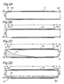
- the heat equalizing member 8 is generally composed of, as shown in Fig. 2D , a cylindrical copper pipe 10 having water 13 as operating fluid enclosed therein, and a heat-resistant releasing layer 12 made of a PFA tube formed in close contact with the outer face of the copper pipe 10.
- the heat equalizing member 8 is biased toward the pressure roller 5 by an unshown pressurizing mechanism using a spring and the like.
- the pressure roller 5 is rotated at a predetermined circumferential speed in the counter clockwise direction shown by arrow b in Fig. 1 with an unshown drive mechanism.
- the heating belt 1 rotates together with the fixing roller 2 in the clockwise direction shown by arrow a in Fig. 1 by following after the rotation of the pressure roller 5 due to frictional force with the pressure roller 5 in the nip section.
- the heat equalizing member 8 also rotates in the clockwise direction shown by arrow c in Fig. 1 by following after the rotation of the pressure roller 5 due to frictional force with the pressure roller 5.
- the exciting coil 3 is provided for generating magnetic flux in response to electric power supply from the high-frequency inverter 70.
- the exciting coil 3 is formed by winding a lead wire bundle into the shape of an ellipse two or more times (about 10 times in this example) along with the longitudinal direction of the fixing roller 2.
- reference sign 3a shows an outward trip portion of the lead wire bundle
- reference sign 3b shows a return trip portion of the lead wire bundle.
- the one lead wire bundle is a publicly known strand (litz wire) with a diameter of about several mm which is formed by bundling 114 strands (copper wires of about 0.18mm-0.20mm in diameter with insulating coating of enamel) in order to enhance conducting efficiency.
- the magnetic body core 4 is composed of a generally angle-shaped main core 4a placed along the outer circumference of the heating belt 1, a central core 4b projecting toward the heating belt 1 from a central section with respect to the circumferential direction of the main core 4a, and edge cores 4c and 4d each projecting toward the heating belt 1 from the opposite end sections with respect to the circumferential direction of the main core 4a.
- the central core 4b is positioned in a gap between the outward trip portion 3a and the return trip portion 3b of the exciting coil 3.
- the edge cores 4c and 4d cover the outer edges of the outward trip portion 3a and the return trip portion 3b of the exciting coil 3.
- Each component member of the magnetic body core 4 is made of MnZn-based ferrite.
- the magnetic flux generated by the exciting coil 3 forms a magnetic circuit starting from the central core 4b, passing through a left-hand portion of the main core 4a in Fig. 1 , the edge core 4c and the heat-generating layer of the heating belt 1, and returning to the central core 4b.
- the magnetic flux also symmetrically forms a magnetic circuit starting from the central core 4b, passing through a right-hand portion of the main core 4a in Fig. 1 , the edge core 4d and the heat-generating layer of the heating belt 1, and returning to the central core 4b.
- the magnetic flux passes along the heat-generating layer of the heating belt 1, and the magnetic flux alternates so that an eddy current is generated on the heat-generating layer to generate heat.
- the temperature sensor 50 is, for example, a noncontact infrared temperature sensor, and is placed so as to face the outer face of heating belt 1 in close proximity. It is to be noted that a contact type thermistor may be used as the temperature sensor 50.
- the detection signal of the temperature sensor 50 is inputted into the control circuit 60.
- the control circuit 60 controls the high-frequency inverter 70 based on the detection signal of the temperature sensor 50 to increase or decrease the electric power supply from the high-frequency inverter 70 to the exciting coil 3 so that the surface temperature of the heating belt 1 can be kept at a target temperature suitable for fixing.
- a thermostat and other instruments to ensure security may be used in place of the infrared temperature sensor.
- the pressure roller 5 rotates counter clockwise in Fig. 1 , and following after this rotation, the fixing roller 2 and the heating belt 1 rotate clockwise in Fig. 1 .
- automatic control is carried out so that the heat-generating layer of the heating belt 1 generates heat through electromagnetic induction by the magnetic flux generated by the exciting coil 3 and thereby the surface temperature of the heating belt 1 can be kept at the target temperature (about 180 °C in this example).
- a paper sheet 90 as a sheet with an unfixed toner image 91 formed on one side thereof is sent from the right side in Fig. 1 into the nip section composed of the heating belt 1 and the pressure roller 5 by an unshown conveying mechanism.
- the paper sheet 90 sent into the nip section is heated by the heating belt 1 while it passes through the nip section. As a result, the unfixed toner image 91 is fixed onto the paper sheet 90.
- the paper sheet 90 which passed through the nip section is discharged to the left side in Fig. 1 . It is to be noted that the paper sheet 90 may be replaced with an OHP sheet and the like.
- the heat in an area in the width direction of the heating belt 1 where the paper sheets do not come into contact is not removed, and therefore heat tends to remain in the non-paper feed area of the heating belt 1 and the pressure roller 5, resulting in local temperature rise.
- the heat equalizing member 8 removes the heat in the non-paper feed area of the heating belt 1 and the pressure roller 5, and equalizes the heat in the longitudinal direction of the heat equalizing member 8 with use of the latent heat of the enclosed operating fluid. This makes it possible to reduce temperature distribution difference in the width direction of the heating belt 1 (longitudinal direction of the pressure roller 5) and to achieve heat equalization.
- toner overmelts in the non-paper feed area and thereby high temperature offset may be generated, or uneven glossiness may be generated when large-size paper sheets are fed after feeding of the small-size paper sheets. If temperature rises further, peripheral component members of the fixing device may also melt.
- the heat-resistant releasing layer 12 made of PFA is provided on the outermost circumference of the heat equalizing member 8, so that contamination can scarcely attach to the surface.
- heat equalizing capability is excellent and heat capacity is small. Since the heat equalizing member 8 has a smaller number of component members than the conventional example ( JP H7-28351 A ) using a reinforcement pipe, it can be manufactured at lower costs. Moreover, since the heat-resistant releasing layer 12 has resistance to the heat of target temperature suitable for fixing (about 180 °C in this example), the heat equalizing member 8 can stay in stable contact with the pressure roller 5 over a long period of time. Therefore, the heat equalizing effect is stabilized and maintained.
- Figs. 2A - 2D show the manufacturing steps for the heat equalizing member 8.
- an elongated copper pipe 10 is prepared which has a left end 10e as one end being closed and a right end 10f as the other end being opened.
- the copper pipe 10 is an integrated product of 21mm in diameter and 0.8mm in thickness.
- a primer 11 for enhancing the adhesive strength of the heat-resistant releasing layer described below is applied to the outer face 10a of the copper pipe 10.
- the primer 11 is made of a material formed by dispersing a binder component having adhesiveness to metal (such as acrylics, polyamidoimide, polyimide, poly phenylene sulphide, polyether sulphone and the like) and a fluororesin component having adhesiveness to fluororesin (such as polytetrafluoroethylene, tetrafluoroethylene perfluoroalkyl vinyl ether copolymers, tetrafluoroethylene hexafluoropropylene copolymers, and blends thereof).
- the material is generally used for bonding metal object and fluororesin.
- the heat-resistant releasing layer 12 made of PFA is formed in close contact with the outer face 10a of the copper pipe 10 (more specifically, with the outer face of the primer 11).
- the heat-resistant releasing layer 12 is formed by covering the outer circumference of the copper pipe 10 with a PFA tube and performing calcination at about 400 °C.
- the area for forming the heat-resistant releasing layer 12 is set to be only an internal area A of the copper pipe 10 excluding outer edge areas B and C at opposite end sides with respect to the longitudinal direction of the copper pipe 10.
- the internal area A is substantially equivalent to the area through which the maximum-size paper sheet expected in this fixing device passes.
- the area for applying the primer 11 is set to have a margin so as to be slightly larger than the internal area A with respect to the longitudinal direction of the copper pipe 10.
- an unshown vacuum pump is connected to the right end 10f of the pipe 10 to vacuum the inside of the pipe 10, and in this vacuumed state, crushing as the second plastic working is performed to close the right end 10f of the pipe 10 (preliminary sealing).
- the heat of the welding may increase the temperature of the pipe 10, which may deteriorate or damage the heat-resistant releasing layer 12 if no measure is devised. Accordingly, in the present embodiment, heat is radiated with use of the heat sink tool 20 during welding as shown in Fig. 3 .
- the heat sink tool 20 includes a pair of fixtures 15A, 15B for holding and fixing an outer edge area C of the right end 10f side of the pipe 10 (more precisely, a portion 10c left behind with the original outer diameter in the outer edge area C) from both sides, a pair of cooling heat pipes 16A, 16B, whose one ends are respectively inserted into the fixtures 15A, 15B, and a pair of heat sinks 17A, 17B attached to the other end sides of the cooling heat pipes 16A, 16B.
- the fixtures 15A, 15B and the heat sinks 17A, 17B are made of components with sufficient thermal conductivity such as aluminum and copper.
- the surfaces of the fixtures 15A, 15B on the pipe 10 side are formed into curved surfaces with the same curvature as the original outer diameter of the pipe 10 so as to enlarge the contact area with the pipe 10.
- the heat sinks 17A, 17B have a large number of fins so as to enlarge the surface area.
- the cooling heat pipes 16A, 16B are made of cylindrical copper pipes with the water as operating fluid enclosed therein.
- the portion 10c in the outer edge area C of the right end 10f side of the pipe 10, which is left behind with the original outer diameter, is held by the fixtures 15A, 15B from both sides and fixed therein.
- the heat sinks 17A, 17B are cooled with a cooling fan 18.
- the right end 10f of the pipe 10 is sealed by welding (brazing).
- the heat of the welding is transported from the right end 10f of the pipe 10 to the portion 10c left behind with the original outer diameter, the fixtures 15A, 15B, the cooling heat pipes 16A, 16B, and the heat sinks 17A, 17B.
- the cooling fan 18 With the aid of the cooling fan 18, the heat is efficiently radiated into atmosphere from the heat sinks 17A, 17B.
- the temperature of the internal area A of the pipe 10 is kept below about 260 °C which is the temperature that the heat-resistant releasing layer 12 can withstand. Therefore, it becomes possible to prevent the heat-resistant releasing layer 12 of the heat equalizing member 8 from being deteriorated by the heat of welding, and to prevent the pipe 10 from being broken and damaged resulting from an increase in internal pressure of the pipe 10.
- a coolant circulation pipe going through the fixtures 15A, 15B may be provided to perform water cooling and oil cooling with use of water and oil.
- the heat-resistant releasing layer 12 was formed by covering the outer circumference of the copper pipe 10 with a PFA tube and by performing calcination. It should naturally be understood that the present invention is not limited to this example.
- the heat-resistant releasing layer 12 may be formed by applying the powder electrostatic coating of the fluororesin to the outer face of the internal area A of the pipe 10 and then calcinating the fluororesin.
- the heat-resistant releasing layer 12 may also be formed by applying a dispersion paint, which is constituted of fluororesin powder dispersed into water, to the outer face of the internal area A of the pipe 10 and then calcinating the dispersion paint.
- a dispersion paint which is constituted of fluororesin powder dispersed into water
- the heat-resistant releasing layer 12 may also be formed by soaking the outer face of the internal area A of the pipe 10 in melt fluororesin to attach the fluororesin around the outer face, making the thickness of the fluororesin attached around the outer face uniform with a thickness control blade, and then calcinating the fluororesin.
- the heat-resistant releasing layer 12 may also be formed by coating the outer face of the internal area A of the pipe 10 with melt fluororesin with use of a roll coater and then calcinating the fluororesin.
- the material of the pipe 10 was copper, aluminum and other materials may be used instead.
- metallic materials with good thermal conductivity and a certain level of rigidity are preferable.
- the material of the heat-resistant releasing layer 12 was PFA, the material is not limited thereto.
- the material of the heat-resistant releasing layer 12 may be fluororesin such as PTFE (polytetrafluoroethylene), FEP (tetrafluoroethylene hexafluoropropylene copolymer), and PFEP (perfluoro ethylene hexafluoropropylene copolymer) in addition to PFA. Since these are fluororesins, they are excellent in heat resistance and releasability, and inexpensive. Their use, therefore, is desirable.
- a manufacturing method of a heat equalizing member for a fixing device comprises:
- first plastic working is performed to reduce a diameter of the other end of the pipe.
- the operating fluid already injected is not easily spilled from the pipe during and after injection of the operating fluid.
- the diameter of the other end of the pipe is reduced by the first plastic working, so that the other end of the pipe can easily be closed in the second plastic working.
- an area on the outer face of the pipe where the heat-resistant releasing layer is formed is only an internal area excluding outer edge areas at opposite end sides of the pipe with respect to a longitudinal direction of the pipe, and when the welding is performed, a heat sink tool is brought into contact with the outer edge area on the other end side of the pipe, so that heat is radiated from the outer edge area through the heat sink tool.
- the "outer edge areas" of the pipe are equivalent to areas other than the internal area through which the maximum-size sheet (recording medium) expected in the fixing device employing the heat equalizing member for a fixing device passes, i.e., the areas which do not contribute to fixing of toner images.
- the heat equalizing member for a fixing device in this embodiment, when the welding is performed, a heat sink tool is brought into contact with the outer edge area on the other end side of the pipe, so that heat is radiated from the outer edge area through the heat sink tool. Therefore, it becomes possible to prevent the heat-resistant releasing layer of the heat equalizing member from being deteriorated by the heat of the welding, and to prevent the pipe from being broken and damaged resulting from an increase in internal pressure of the pipe.
- formation of the heat-resistant releasing layer is performed by applying powder electrostatic coating of the fluororesin to the outer face of the internal area of the pipe and then calcinating the fluororesin.
- the heat-resistant releasing layer is formed easily.
- formation of the heat-resistant releasing layer is performed by applying a dispersion paint, which is constituted of fluororesin powder dispersed into water, to the outer face of the internal area of the pipe and then calcinating the dispersion paint.
- a dispersion paint which is constituted of fluororesin powder dispersed into water
- the heat-resistant releasing layer is formed easily.
- formation of the heat-resistant releasing layer is performed by covering the outer face of the internal area of the pipe with a tube made of fluororesin and then calcinating the tube.
- the heat-resistant releasing layer is formed easily.
- formation of the heat-resistant releasing layer is performed by soaking the outer face of the internal area of the pipe in melt fluororesin to attach the fluororesin around the outer face, making a thickness of the fluororesin attached around the outer face uniform with a thickness control blade, and then calcinating the fluororesin.
- the heat-resistant releasing layer is formed easily.
- formation of the heat-resistant releasing layer is performed by coating the outer face of the internal area of the pipe with melt fluororesin with use of a roll coater and then calcinating the fluororesin.
- the heat-resistant releasing layer is formed easily.
- a heat equalizing member for a fixing device comprises:
- the heat-resistant releasing layer is formed only in an internal area excluding outer edge areas at opposite end sides of the pipe with respect to a longitudinal direction of the pipe.
- the heat-resistant releasing layer is formed only in the internal area of the pipe excluding the outer edge areas at the opposite end sides with respect to the longitudinal direction of the pipe, and therefore when the pipe is sealed, the heat sink tool is brought into contact with the outer edge area, so that heat can be radiated from the outer edge area through the heat sink tool.
- the heat-resistant releasing layer is made of fluororesin.
- the material of the heat-resistant releasing layer is fluororesin, it is excellent in heat resistance and releasability, and inexpensive.
Landscapes
- Engineering & Computer Science (AREA)
- Physics & Mathematics (AREA)
- Mechanical Engineering (AREA)
- General Physics & Mathematics (AREA)
- Thermal Sciences (AREA)
- General Engineering & Computer Science (AREA)
- Life Sciences & Earth Sciences (AREA)
- Sustainable Development (AREA)
- Fixing For Electrophotography (AREA)
Applications Claiming Priority (4)
| Application Number | Priority Date | Filing Date | Title |
|---|---|---|---|
| JP2008159286A JP4766077B2 (ja) | 2008-06-18 | 2008-06-18 | 定着装置および画像形成装置 |
| JP2008223149A JP2010060595A (ja) | 2008-09-01 | 2008-09-01 | 定着装置および画像形成装置 |
| JP2008239538A JP2010072328A (ja) | 2008-09-18 | 2008-09-18 | 定着装置および画像形成装置 |
| JP2008318328A JP4760901B2 (ja) | 2008-12-15 | 2008-12-15 | 定着装置用均熱部材の製造方法および定着装置用均熱部材 |
Publications (2)
| Publication Number | Publication Date |
|---|---|
| EP2136265A2 true EP2136265A2 (fr) | 2009-12-23 |
| EP2136265A3 EP2136265A3 (fr) | 2010-12-22 |
Family
ID=41137741
Family Applications (1)
| Application Number | Title | Priority Date | Filing Date |
|---|---|---|---|
| EP09007925A Withdrawn EP2136265A3 (fr) | 2008-06-18 | 2009-06-17 | Procédé de fabrication d'élément d'équilibrage thermique pour dispositif de fixation et élément d'équilibrage thermique pour le dispositif de fixation |
Country Status (2)
| Country | Link |
|---|---|
| US (1) | US8240050B2 (fr) |
| EP (1) | EP2136265A3 (fr) |
Cited By (1)
| Publication number | Priority date | Publication date | Assignee | Title |
|---|---|---|---|---|
| US8915058B2 (en) | 2010-06-03 | 2014-12-23 | Rolls-Royce Plc | Heat transfer arrangement for fluid-washed surfaces |
Families Citing this family (4)
| Publication number | Priority date | Publication date | Assignee | Title |
|---|---|---|---|---|
| JP2010060595A (ja) * | 2008-09-01 | 2010-03-18 | Konica Minolta Business Technologies Inc | 定着装置および画像形成装置 |
| JP2010243077A (ja) * | 2009-04-07 | 2010-10-28 | Sony Corp | 熱輸送デバイスの製造方法、熱輸送デバイス、電子機器及びカシメピン |
| JP5936938B2 (ja) * | 2012-07-11 | 2016-06-22 | 住友重機械工業株式会社 | 極低温蓄冷器の製造方法 |
| JP6815769B2 (ja) * | 2016-07-12 | 2021-01-20 | キヤノン株式会社 | 制御装置 |
Citations (1)
| Publication number | Priority date | Publication date | Assignee | Title |
|---|---|---|---|---|
| JPH0728351A (ja) | 1993-02-04 | 1995-01-31 | Ricoh Co Ltd | 画像定着装置 |
Family Cites Families (41)
| Publication number | Priority date | Publication date | Assignee | Title |
|---|---|---|---|---|
| JPS5848838B2 (ja) | 1977-02-28 | 1983-10-31 | 株式会社リコー | ヒ−トパイプロ−ラ−の製造方法 |
| JPS5627886A (en) | 1979-08-15 | 1981-03-18 | Furukawa Electric Co Ltd:The | Manufacture for heat pipe with tapered inside surface for rotary shaft |
| DE3851403T2 (de) * | 1987-10-14 | 1995-01-19 | Canon Kk | Bildfixierwalze und Bildfixiergerät mit dieser Walze. |
| US4977431A (en) * | 1987-10-26 | 1990-12-11 | Mita Industrial Co., Ltd. | Fixing apparatus and method of controlling temperature of the same |
| JP2589386B2 (ja) | 1989-11-24 | 1997-03-12 | 富士通アイソテック株式会社 | 熱ローラ定着器 |
| JPH0736303A (ja) | 1993-07-16 | 1995-02-07 | Canon Inc | 定着装置 |
| JPH0764420A (ja) | 1993-08-26 | 1995-03-10 | Oki Electric Ind Co Ltd | 熱定着装置 |
| JPH08248797A (ja) | 1995-03-13 | 1996-09-27 | Furukawa Electric Co Ltd:The | 定着装置用加熱ロール及びその製造方法 |
| JP3593199B2 (ja) | 1995-12-22 | 2004-11-24 | 株式会社リコー | 画像形成装置 |
| JPH10291045A (ja) | 1997-04-18 | 1998-11-04 | Diamond Electric Mfg Co Ltd | ヒートパイプの封止部加工方法 |
| US6132815A (en) * | 1997-04-25 | 2000-10-17 | Canon Kabushiki Kaisha | Fluororesin-coating process |
| US6183869B1 (en) * | 1997-05-02 | 2001-02-06 | Fuji Xerox Co., Ltd. | Primer composition, fixing member, and fixing device using the fixing member |
| JP3703012B2 (ja) | 1998-07-21 | 2005-10-05 | キヤノンファインテック株式会社 | 定着装置 |
| JP3825950B2 (ja) | 2000-02-15 | 2006-09-27 | キヤノン株式会社 | 像加熱装置及び画像形成装置 |
| JP2002055552A (ja) | 2000-08-11 | 2002-02-20 | Toshiba Tec Corp | 定着装置 |
| JP2002062752A (ja) | 2000-08-18 | 2002-02-28 | Konica Corp | 画像形成装置 |
| JP2002082569A (ja) | 2000-09-08 | 2002-03-22 | Konica Corp | 画像定着装置および画像形成装置 |
| US6445902B1 (en) | 2001-03-28 | 2002-09-03 | Hewlett-Packard Company | Simplified fusing system |
| JP2003098877A (ja) | 2001-09-20 | 2003-04-04 | Konica Corp | 定着装置および画像形成装置 |
| JP2003131504A (ja) | 2001-10-24 | 2003-05-09 | Canon Inc | 加熱定着装置 |
| JP2004077886A (ja) * | 2002-08-20 | 2004-03-11 | Ricoh Co Ltd | 定着部材及びその製造方法並びにそれを有する画像形成装置 |
| KR100445007B1 (ko) * | 2002-10-22 | 2004-08-21 | 삼성전자주식회사 | 전자사진 화상형성장치의 정착 장치 |
| JP2005037859A (ja) | 2003-06-25 | 2005-02-10 | Matsushita Electric Ind Co Ltd | 定着装置及びこれを備えた画像形成装置 |
| US7065315B2 (en) * | 2003-06-30 | 2006-06-20 | Kabushiki Kaisha Toshiba | Fixing apparatus |
| JP4469169B2 (ja) | 2003-07-16 | 2010-05-26 | 株式会社東芝 | 定着装置 |
| US7257361B2 (en) * | 2003-07-10 | 2007-08-14 | Kabushiki Kaisha Toshiba | Fixing apparatus |
| JP4342229B2 (ja) | 2003-07-30 | 2009-10-14 | 信越ポリマー株式会社 | 定着ローラ |
| JP4653452B2 (ja) * | 2003-10-24 | 2011-03-16 | 株式会社リコー | 定着部材、定着装置、及び画像形成装置 |
| JP2005305809A (ja) | 2004-04-21 | 2005-11-04 | Fuji Xerox Co Ltd | ポリイミド樹脂無端ベルトおよびその製造方法 |
| CN100413061C (zh) * | 2004-06-07 | 2008-08-20 | 鸿富锦精密工业(深圳)有限公司 | 一种热管及其制造方法 |
| JP4674081B2 (ja) * | 2004-12-20 | 2011-04-20 | 株式会社リコー | 定着装置、及び画像形成装置 |
| JP2006200775A (ja) | 2005-01-19 | 2006-08-03 | Furukawa Sky Kk | ヒートパイプ及びその製造方法 |
| US7349660B2 (en) * | 2005-06-28 | 2008-03-25 | Xerox Corporation | Low mass fuser apparatus with substantially uniform axial temperature distribution |
| US7327978B2 (en) * | 2005-06-29 | 2008-02-05 | Xerox Corporation | Heat pipe fusing member |
| JP4655846B2 (ja) | 2005-09-15 | 2011-03-23 | 富士ゼロックス株式会社 | 定着装置、画像形成装置および定着方法 |
| CN1940452A (zh) * | 2005-09-30 | 2007-04-04 | 富准精密工业(深圳)有限公司 | 热管封口方法 |
| JP2007108213A (ja) | 2005-10-11 | 2007-04-26 | Konica Minolta Business Technologies Inc | 定着装置 |
| JP2007108212A (ja) | 2005-10-11 | 2007-04-26 | Konica Minolta Business Technologies Inc | 定着装置 |
| JP4281779B2 (ja) * | 2006-10-20 | 2009-06-17 | コニカミノルタビジネステクノロジーズ株式会社 | 定着装置および画像形成装置 |
| JP2010060595A (ja) * | 2008-09-01 | 2010-03-18 | Konica Minolta Business Technologies Inc | 定着装置および画像形成装置 |
| JP4766077B2 (ja) * | 2008-06-18 | 2011-09-07 | コニカミノルタビジネステクノロジーズ株式会社 | 定着装置および画像形成装置 |
-
2009
- 2009-06-09 US US12/480,832 patent/US8240050B2/en not_active Expired - Fee Related
- 2009-06-17 EP EP09007925A patent/EP2136265A3/fr not_active Withdrawn
Patent Citations (1)
| Publication number | Priority date | Publication date | Assignee | Title |
|---|---|---|---|---|
| JPH0728351A (ja) | 1993-02-04 | 1995-01-31 | Ricoh Co Ltd | 画像定着装置 |
Cited By (1)
| Publication number | Priority date | Publication date | Assignee | Title |
|---|---|---|---|---|
| US8915058B2 (en) | 2010-06-03 | 2014-12-23 | Rolls-Royce Plc | Heat transfer arrangement for fluid-washed surfaces |
Also Published As
| Publication number | Publication date |
|---|---|
| US8240050B2 (en) | 2012-08-14 |
| EP2136265A3 (fr) | 2010-12-22 |
| US20090314478A1 (en) | 2009-12-24 |
Similar Documents
| Publication | Publication Date | Title |
|---|---|---|
| CN102289178B (zh) | 定影装置及其图像形成装置 | |
| US8050612B2 (en) | Fixing device having a temperature-uniforming roller | |
| CN101609294B (zh) | 定影装置用均热部件的制造方法以及定影装置用均热部件 | |
| US9857743B2 (en) | Fixing device and image forming apparatus having the same | |
| US8240050B2 (en) | Manufacturing method of heat equalizing member for fixing device and heat equalizing member for fixing device | |
| US8811850B2 (en) | Fixing device and image forming apparatus including the same | |
| JP2006293079A (ja) | 像加熱装置 | |
| JP6270457B2 (ja) | 像加熱装置 | |
| JP2006259722A (ja) | 画像形成装置の定着装置 | |
| US20160116871A1 (en) | Fixing device and image forming apparatus | |
| JP4999496B2 (ja) | 定着装置及び画像形成装置 | |
| JP4539407B2 (ja) | 定着装置 | |
| EP3291021A1 (fr) | Courroie et appareil de fixation | |
| US20120057911A1 (en) | Heating roller comprising induction heating coil made of nickel alloy, fixing unit and image forming apparatus having the same | |
| JP2007242635A (ja) | 加熱装置及び画像形成装置 | |
| US8983348B2 (en) | Fixing device and image forming apparatus including same | |
| JP5194769B2 (ja) | 誘導加熱装置,定着装置および画像形成装置 | |
| US9268271B1 (en) | Fixing device, image forming apparatus and drive load reduction method of the fixing device | |
| JP4760901B2 (ja) | 定着装置用均熱部材の製造方法および定着装置用均熱部材 | |
| US20160259280A1 (en) | Fixing device and image forming apparatus | |
| JP5699676B2 (ja) | 定着装置及び画像形成装置 | |
| JP7176322B2 (ja) | 定着装置及びこれを用いた画像形成装置 | |
| CN106338899A (zh) | 定影装置 | |
| JP2005234252A (ja) | 定着装置及び画像形成装置 | |
| JP4456941B2 (ja) | 定着装置及び画像形成装置 |
Legal Events
| Date | Code | Title | Description |
|---|---|---|---|
| PUAI | Public reference made under article 153(3) epc to a published international application that has entered the european phase |
Free format text: ORIGINAL CODE: 0009012 |
|
| AK | Designated contracting states |
Kind code of ref document: A2 Designated state(s): AT BE BG CH CY CZ DE DK EE ES FI FR GB GR HR HU IE IS IT LI LT LU LV MC MK MT NL NO PL PT RO SE SI SK TR |
|
| RIC1 | Information provided on ipc code assigned before grant |
Ipc: B21D 53/06 20060101ALI20100831BHEP Ipc: G03G 15/20 20060101AFI20091014BHEP |
|
| PUAL | Search report despatched |
Free format text: ORIGINAL CODE: 0009013 |
|
| AK | Designated contracting states |
Kind code of ref document: A3 Designated state(s): AT BE BG CH CY CZ DE DK EE ES FI FR GB GR HR HU IE IS IT LI LT LU LV MC MK MT NL NO PL PT RO SE SI SK TR |
|
| AX | Request for extension of the european patent |
Extension state: AL BA RS |
|
| 17P | Request for examination filed |
Effective date: 20110622 |
|
| STAA | Information on the status of an ep patent application or granted ep patent |
Free format text: STATUS: THE APPLICATION HAS BEEN WITHDRAWN |
|
| 18W | Application withdrawn |
Effective date: 20130304 |