EP2128472B1 - Vorrichtung zur Kupplungssteuerung - Google Patents
Vorrichtung zur Kupplungssteuerung Download PDFInfo
- Publication number
- EP2128472B1 EP2128472B1 EP09155587.0A EP09155587A EP2128472B1 EP 2128472 B1 EP2128472 B1 EP 2128472B1 EP 09155587 A EP09155587 A EP 09155587A EP 2128472 B1 EP2128472 B1 EP 2128472B1
- Authority
- EP
- European Patent Office
- Prior art keywords
- clutch
- control
- correction amount
- drive wheel
- vehicle
- Prior art date
- Legal status (The legal status is an assumption and is not a legal conclusion. Google has not performed a legal analysis and makes no representation as to the accuracy of the status listed.)
- Active
Links
Images


Classifications
-
- F—MECHANICAL ENGINEERING; LIGHTING; HEATING; WEAPONS; BLASTING
- F16—ENGINEERING ELEMENTS AND UNITS; GENERAL MEASURES FOR PRODUCING AND MAINTAINING EFFECTIVE FUNCTIONING OF MACHINES OR INSTALLATIONS; THERMAL INSULATION IN GENERAL
- F16D—COUPLINGS FOR TRANSMITTING ROTATION; CLUTCHES; BRAKES
- F16D48/00—External control of clutches
- F16D48/06—Control by electric or electronic means, e.g. of fluid pressure
- F16D48/08—Regulating clutch take-up on starting
-
- F—MECHANICAL ENGINEERING; LIGHTING; HEATING; WEAPONS; BLASTING
- F16—ENGINEERING ELEMENTS AND UNITS; GENERAL MEASURES FOR PRODUCING AND MAINTAINING EFFECTIVE FUNCTIONING OF MACHINES OR INSTALLATIONS; THERMAL INSULATION IN GENERAL
- F16D—COUPLINGS FOR TRANSMITTING ROTATION; CLUTCHES; BRAKES
- F16D48/00—External control of clutches
- F16D48/06—Control by electric or electronic means, e.g. of fluid pressure
- F16D48/066—Control of fluid pressure, e.g. using an accumulator
-
- F—MECHANICAL ENGINEERING; LIGHTING; HEATING; WEAPONS; BLASTING
- F16—ENGINEERING ELEMENTS AND UNITS; GENERAL MEASURES FOR PRODUCING AND MAINTAINING EFFECTIVE FUNCTIONING OF MACHINES OR INSTALLATIONS; THERMAL INSULATION IN GENERAL
- F16D—COUPLINGS FOR TRANSMITTING ROTATION; CLUTCHES; BRAKES
- F16D2500/00—External control of clutches by electric or electronic means
- F16D2500/10—System to be controlled
- F16D2500/11—Application
- F16D2500/1107—Vehicles
- F16D2500/1117—Motorcycle
-
- F—MECHANICAL ENGINEERING; LIGHTING; HEATING; WEAPONS; BLASTING
- F16—ENGINEERING ELEMENTS AND UNITS; GENERAL MEASURES FOR PRODUCING AND MAINTAINING EFFECTIVE FUNCTIONING OF MACHINES OR INSTALLATIONS; THERMAL INSULATION IN GENERAL
- F16D—COUPLINGS FOR TRANSMITTING ROTATION; CLUTCHES; BRAKES
- F16D2500/00—External control of clutches by electric or electronic means
- F16D2500/30—Signal inputs
- F16D2500/302—Signal inputs from the actuator
- F16D2500/3022—Current
-
- F—MECHANICAL ENGINEERING; LIGHTING; HEATING; WEAPONS; BLASTING
- F16—ENGINEERING ELEMENTS AND UNITS; GENERAL MEASURES FOR PRODUCING AND MAINTAINING EFFECTIVE FUNCTIONING OF MACHINES OR INSTALLATIONS; THERMAL INSULATION IN GENERAL
- F16D—COUPLINGS FOR TRANSMITTING ROTATION; CLUTCHES; BRAKES
- F16D2500/00—External control of clutches by electric or electronic means
- F16D2500/30—Signal inputs
- F16D2500/302—Signal inputs from the actuator
- F16D2500/3024—Pressure
-
- F—MECHANICAL ENGINEERING; LIGHTING; HEATING; WEAPONS; BLASTING
- F16—ENGINEERING ELEMENTS AND UNITS; GENERAL MEASURES FOR PRODUCING AND MAINTAINING EFFECTIVE FUNCTIONING OF MACHINES OR INSTALLATIONS; THERMAL INSULATION IN GENERAL
- F16D—COUPLINGS FOR TRANSMITTING ROTATION; CLUTCHES; BRAKES
- F16D2500/00—External control of clutches by electric or electronic means
- F16D2500/30—Signal inputs
- F16D2500/31—Signal inputs from the vehicle
- F16D2500/3108—Vehicle speed
- F16D2500/3111—Standing still, i.e. signal detecting when the vehicle is standing still or bellow a certain limit speed
-
- F—MECHANICAL ENGINEERING; LIGHTING; HEATING; WEAPONS; BLASTING
- F16—ENGINEERING ELEMENTS AND UNITS; GENERAL MEASURES FOR PRODUCING AND MAINTAINING EFFECTIVE FUNCTIONING OF MACHINES OR INSTALLATIONS; THERMAL INSULATION IN GENERAL
- F16D—COUPLINGS FOR TRANSMITTING ROTATION; CLUTCHES; BRAKES
- F16D2500/00—External control of clutches by electric or electronic means
- F16D2500/30—Signal inputs
- F16D2500/31—Signal inputs from the vehicle
- F16D2500/3114—Vehicle wheels
- F16D2500/3115—Vehicle wheel speed
-
- F—MECHANICAL ENGINEERING; LIGHTING; HEATING; WEAPONS; BLASTING
- F16—ENGINEERING ELEMENTS AND UNITS; GENERAL MEASURES FOR PRODUCING AND MAINTAINING EFFECTIVE FUNCTIONING OF MACHINES OR INSTALLATIONS; THERMAL INSULATION IN GENERAL
- F16D—COUPLINGS FOR TRANSMITTING ROTATION; CLUTCHES; BRAKES
- F16D2500/00—External control of clutches by electric or electronic means
- F16D2500/30—Signal inputs
- F16D2500/312—External to the vehicle
- F16D2500/3125—Driving resistance, i.e. external factors having an influence in the traction force, e.g. road friction, air resistance, road slope
- F16D2500/3127—Road slope
-
- F—MECHANICAL ENGINEERING; LIGHTING; HEATING; WEAPONS; BLASTING
- F16—ENGINEERING ELEMENTS AND UNITS; GENERAL MEASURES FOR PRODUCING AND MAINTAINING EFFECTIVE FUNCTIONING OF MACHINES OR INSTALLATIONS; THERMAL INSULATION IN GENERAL
- F16D—COUPLINGS FOR TRANSMITTING ROTATION; CLUTCHES; BRAKES
- F16D2500/00—External control of clutches by electric or electronic means
- F16D2500/30—Signal inputs
- F16D2500/314—Signal inputs from the user
- F16D2500/31406—Signal inputs from the user input from pedals
- F16D2500/31426—Brake pedal position
-
- F—MECHANICAL ENGINEERING; LIGHTING; HEATING; WEAPONS; BLASTING
- F16—ENGINEERING ELEMENTS AND UNITS; GENERAL MEASURES FOR PRODUCING AND MAINTAINING EFFECTIVE FUNCTIONING OF MACHINES OR INSTALLATIONS; THERMAL INSULATION IN GENERAL
- F16D—COUPLINGS FOR TRANSMITTING ROTATION; CLUTCHES; BRAKES
- F16D2500/00—External control of clutches by electric or electronic means
- F16D2500/70—Details about the implementation of the control system
- F16D2500/706—Strategy of control
- F16D2500/70605—Adaptive correction; Modifying control system parameters, e.g. gains, constants, look-up tables
Definitions
- the present invention relates to a clutch control device, and more particularly to a clutch control device which can calculate a control correction amount according to a clutch control amount at starting of rotation of a drive wheel and can properly correct the clutch control amount by using the control correction amount calculated above. See as the closest prior art US2002/042327 , US2006/106520 and DE102006037389 .
- a clutch device having friction plates (clutch plates or clutches) for transmitting a torque from a power source to a drive wheel by a frictional force and an actuator for driving the friction plates.
- friction plates clutch plates or clutches
- an actuator for driving the friction plates.
- Such a problem can be solved by detecting the amount of movement of the clutch plates from their separate position to their contact position and increasing the driving amount by the actuator according to an increase in the amount of movement of the clutch plates.
- Patent Document 1 discloses such a configuration that the amount of movement of the clutch plates is detected according to the position of a member displaced by the actuator.
- a clutch control device for a clutch for connecting and disconnecting the transmission of a rotational drive force from a power source to a drive wheel in a vehicle
- the clutch control device including clutch control means for controlling a control amount for the clutch; drive wheel rotation start detecting means for detecting the start of rotation of the drive wheel; and control correction amount calculating means for calculating a control correction amount for the clutch according to the difference between the clutch control amount detected at starting of rotation of the drive wheel and a predetermined reference value; the clutch control means applying the control correction amount to the control amount for the clutch to thereby control the clutch.
- control correction amount calculating means calculates a control correction amount to be applied to clutch control during running of the vehicle and a control correction amount to be applied to invalid stroke filling control at starting of the vehicle.
- the drive wheel rotation start detecting means detects the start of rotation from the stopped condition of the drive wheel according to an output pulse from a vehicle speed sensor for directly detecting a rotational speed of the drive wheel.
- the clutch control device further includes inclination angle detecting means for detecting an inclination angle of the vehicle in its longitudinal direction, wherein when the inclination angle is larger than a predetermined value, the control correction amount calculating means suspends the calculation of the control correction amount.
- the clutch control device further includes brake operation detecting means for detecting a brake operation in the vehicle, wherein when the brake operation is detected, the control correction amount calculating means suspends the calculation of the control correction amount.
- the clutch is a twin clutch type clutch composed of a first clutch and a second clutch provided on a main shaft; the engaged condition of the first clutch and the engaged condition of the second clutch being alternately switched every time a shift operation is performed, thereby transmitting the rotational drive force from the power source to the drive wheel.
- the clutch control device further includes warning means for giving a warning, wherein when the control correction amount exceeds a predetermined value, the control correction amount calculating means gives the warning through the warning means.
- the clutch is driven by an actuator, and the control amount for the clutch is a control current value supplied to the actuator.
- the clutch is a hydraulic clutch
- the control amount for the clutch is an oil pressure generated in the clutch.
- the control correction amount calculating means calculates the clutch control correction amount according to the difference between the clutch control amount detected at starting of rotation of the drive wheel and the predetermined reference value, and the clutch control means applies the clutch control correction amount calculated above to the clutch control amount to thereby control the clutch. Accordingly, even when the clutch control amount at starting of rotation of the drive wheel is varied due to variations in quality of the clutch in manufacturing or an increase in friction in a driving force transmitting system, the clutch control can be performed by applying a control correction amount according to the above variations in clutch control amount. As a result, a shifting feel at starting or during running can be made stable.
- the control correction amount calculating means calculates a control correction amount to be applied to clutch control during running of the vehicle and a control correction amount to be applied to invalid stroke filling control at starting of the vehicle.
- the control correction amount during running has an effect on the magnitude of a clutch pressure for transmitting a rotational drive force and variations in clutch pressure upon shifting, whereas the control correction amount at starting has an effect on the time period from the timing of start of driving of the clutch in its engaging direction to the timing of contact of the clutch plates. Accordingly, both of the control correction amount during running and the control correction amount at starting can be calculated according to the clutch control amount detected at starting of rotation of the drive wheel.
- the drive wheel rotation start detecting means detects the start of rotation from the stopped condition of the drive wheel according to an output pulse from a vehicle speed sensor for directly detecting a rotational speed of the drive wheel. Accordingly, the timing of start of rotation of the drive wheel can be accurately detected.
- the clutch control device further includes inclination angle detecting means for detecting an inclination angle of the vehicle in its longitudinal direction, wherein when the inclination angle is larger than a predetermined value, the control correction amount calculating means suspends the calculation of the control correction amount. Accordingly, in the case that a proper control correction amount cannot be calculated at starting on an upward or downward slope, the operational processing by the control correction amount calculating means is suspended to thereby reduce the burden on the control correction amount calculating means.
- the clutch control device further includes brake operation detecting means for detecting a brake operation in the vehicle, wherein when the brake operation is detected, the control correction amount calculating means suspends the calculation of the control correction amount. Accordingly, in the case that a proper control correction amount cannot be calculated due to the brake operation, the operation processing by the control correction amount calculating means is suspended to thereby reduce the burden on the control correction amount calculating means.
- the clutch is a twin clutch type clutch composed of a first clutch and a second clutch provided on a main shaft, wherein the engaged condition of the first clutch and the engaged condition of the second clutch are alternately switched every time a shift operation is performed, thereby transmitting the rotational drive force from the power source to the drive wheel. Accordingly, the clutch control using the control correction amount can be performed also in a twin clutch type transmission.
- the clutch control device further includes warning means for giving a warning, wherein when the control correction amount exceeds a predetermined value, the control correction amount calculating means gives the warning through the warning means. Accordingly, the operator can acknowledge that the clutch control amount required for the start of rotation of the drive wheel has become large, and it is possible to urge the operator to check the wear of the clutch plates and any abnormality in the power transmitting system from the clutch to the drive wheel.
- the clutch is driven by an actuator, and the control amount for the clutch is a control current value supplied to the actuator. Accordingly, the clutch control amount can be easily obtained from an output signal for driving the actuator.
- the clutch is a hydraulic clutch
- the control amount for the clutch is an oil pressure generated in the clutch. Accordingly, the clutch control amount can be easily obtained from an output value from an oil pressure sensor or the like provided on a hydraulic line for the clutch.
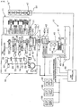
- FIG. 1 is a schematic diagram showing a system configuration of an automatic manual transmission (which will be hereinafter abbreviated to AMT) 16 as an automatic transmission and its peripheral devices applied to a motorcycle.
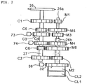
- FIG. 2 is a layout diagram showing shafts and shift gear meshing in the AMT 16.
- the AMT 16 is a twin clutch type transmission having two clutches provided on a main shaft for connecting and disconnecting the transmission of a rotational drive force from an engine.
- the AMT 16 connected to an engine 11 is controlled in operation by a clutch hydraulic device 17 and an AMT control unit 18 as a shift control device.
- the engine 11 has a throttle-by-wire type throttle body 19, and this throttle body 19 is provided with a throttle opening/closing motor 20.
- the AMT 16 includes a forward six-speed transmission 21, first clutch CL1, second clutch CL2, shift drum 24, and shift control motor 25 for rotating the shift drum 24.
- Many gears constituting the transmission 21 are connected fixedly or loosely to a main shaft 26 and a counter shaft 27.
- the main shaft 26 is composed of an inner main shaft 26a and an outer main shaft 26b.
- the inner main shaft 26a is connected to the first clutch CL1, and the outer main shaft 26b is connected to the second clutch CL2.
- Shift gears are axially displaceably provided on the main shaft 26 and the counter shaft 27.
- Shift forks 23 are engaged at their opposite ends to these shift gears and guide grooves (not shown) formed on the shift drum 24.
- a primary drive gear 31 is connected to an output shaft of the engine 11, i.e., a crankshaft 30.
- the primary drive gear 31 is in mesh with a primary driven gear 32.
- the primary driven gear 32 is connected through the first clutch CL1 to the inner main shaft 26a and also connected through the second clutch CL2 to the outer main shaft 26b.
- the AMT 16 further includes an inner main shaft rotational speed sensor 73 and an outer main shaft rotational speed sensor 74 for respectively detecting the rotational speeds of the inner main shaft 26a and the outer main shaft 26b by measuring the rotational speeds of the predetermined shift gears on the counter shaft 27.
- a drive sprocket 35 is connected to the counter shaft 27, and a drive chain (not shown) is wrapped around the drive sprocket 35, so that a drive force is transmitted from the counter shaft 27 through the drive chain to a rear wheel as a drive wheel.
- the AMT 16 further includes an engine speed sensor 36 opposed to the outer circumference of the primary driven gear 32, a gear position sensor 38 for detecting the present gear position according to the rotational position of the shift drum 24, a shift sensor 64 for detecting the rotational position of a shifter driven by the shift control motor 25, and a neutral switch 63 for detecting the neutral position of the shift drum 24.
- the throttle body 19 is provided with a throttle angle sensor 47 for detecting a throttle angle.
- the clutch hydraulic device 17 uses a lubricating oil for the engine 11 as a hydraulic fluid for driving the clutch CL.
- the clutch hydraulic device 17 includes an oil tank 39 and an oil supply passage 40 for supplying oil (hydraulic fluid) from the oil tank 39 to the first clutch CL1 and the second clutch CL2.
- the oil supply passage 40 is provided with a hydraulic pump 41 as an oil pressure source and a valve (electronically controlled valve) 42 as a motor driven actuator.
- a return passage 43 is connected to the oil supply passage 40, and the return passage 43 is provided with a regulator 44 for maintaining the oil pressure to be supplied to the valve 42 at a constant value.
- the valve 42 has a structure capable of individually applying oil pressures to the first clutch CL1 and the second clutch CL2.
- the first and second valves 42a and 42b are respectively provided with oil return passages 45.
- the first valve 42a is connected through a first passage to the first clutch CL1, and this first passage is provided with a first clutch oil pressure sensor 75 for measuring an oil pressure generated in the first clutch CL1.
- the second valve 42b is connected through a second passage to the second clutch CL2, and this second passage is provided with a second clutch oil pressure sensor 76 for measuring an oil pressure generated in the second clutch CL2.
- the AMT control unit 18 Connected to the AMT control unit 18 are a mode switch 49 for switching between an automatic transmission (AT) mode and a manual transmission (MT) mode, a shift select switch 50 for instructing an upshift (UP) or a downshift (DN), and a neutral select switch 51 for switching between a neutral position (N) and a drive position (D).
- the AMT control unit 18 includes a central processing unit (CPU) for controlling the valve 42 and the shift control motor 25 according to output signals from the sensors and switches mentioned above, thereby changing the gear position in the AMT 16 automatically or semi-automatically.
- CPU central processing unit
- the AMT control unit 18 In the case of selecting the AT mode, the AMT control unit 18 automatically changes the gear position according to information such as vehicle speed, engine speed, and throttle angle. In the case of selecting the MT mode, the AMT control unit 18 upshifts or downshifts the transmission 21 according to the operation of the shift select switch 50. However, even in the case of selecting the MT mode, the AMT control unit 18 can execute auxiliary automatic shift control for prevention of engine overrevolution and stall.
- an oil pressure is applied to the valve 42 by the hydraulic pump 41, and this oil pressure is controlled by the regulator 44 so as not to exceed an upper limit.
- the valve 42a or 42b is opened by the instruction from the AMT control unit 18, the oil pressure is applied to the first clutch CL1 or the second clutch CL2, so that the primary driven gear 32 is connected through the first clutch CL1 or the second clutch CL2 to the inner main shaft 26a or the outer main shaft 26b.
- the first clutch CL1 and the second clutch CL2 are biased so as to be disconnected from the inner main shaft 26a and the outer main shaft 26b by return springs (not shown) built in the respective clutches CL1 and CL2.
- the valve 42 for driving the clutches CL1 and CL2 by opening or closing the first and second passages connecting the oil supply passage 40 to the clutches CL1 and CL2 can arbitrarily change the time from a full closed condition to a full open condition of the first and second passages according to a drive signal from the AMT control unit 18.
- the shift control motor 25 rotates the shift drum 24 according to the instruction from the AMT control unit 18.
- the shift forks 23 are selectively displaced in the axial direction of the shift drum 24 according to the shapes of the guide grooves formed on the outer circumference of the shift drum 24. Accordingly, the meshing gears on the counter shaft 27 and the main shaft 26 are changed to thereby effect upshifting or downshifting in the transmission 21.
- the odd-numbered gears are supported to the inner main shaft 26a connected to the first clutch CL1
- the even-numbered gears are supported to the outer main shaft 26b connected to the second clutch CL2. Accordingly, during running with any odd-numbered gear, for example, the supply of an oil pressure to the first clutch CL1 is continued to maintain the engaged condition of the first clutch CL1.
- the next gear position is preliminarily determined by rotating the shift drum 24, so that the gear shift can be effected by only switching the first clutch CL1 to the second clutch CL2.
- the odd-numbered drive gears M1, M3, and M5 are supported to the inner main shaft 26a connected to the first clutch CL1.
- the first drive gear M1 is formed integrally with the inner main shaft 26a.
- the third drive gear M3 is mounted on the inner main shaft 26a so as to be axially slidable and nonrotatable relative to the inner main shaft 26a.
- the fifth drive gear M5 is mounted on the inner main shaft 26a so as to be axially nonslidable and rotatable relative to the inner main shaft 26a.
- the even-numbered drive gears M2, M4, and M6 are supported to the outer main shaft 26b connected to the second clutch CL2.
- the second drive gear M2 is formed integrally with the outer main shaft 26b.
- the fourth drive gear M4 is mounted on the outer main shaft 26b so as to be axially slidable and nonrotatable relative to the outer main shaft 26b.
- the sixth drive gear M6 is mounted on the outer main shaft 26b so as to be axially nonslidable and rotatable relative to the outer main shaft 26b.
- a plurality of driven gears C1 to C6 respectively meshing with the drive gears M1 to M6 are supported to the counter shaft 27.
- the first to fourth driven gears C1 to C4 are mounted on the counter shaft 27 so as to be axially nonslidable and rotatable relative to the counter shaft 27.
- the fifth and sixth driven gears C5 and C6 are mounted on the counter shaft 27 so as to be axially slidable and nonrotatable relative to the counter shaft 27.
- the drive gears M3 and M4 and the driven gears C5 and C6, i.e., the axially slidable gears are adapted to be slid by the respective shift forks 23 to thereby engage or disengage any dog clutch, thus performing a gear shift.
- the engine torque transmitted from the crankshaft 30 to the primary driven gear 32 is transmitted through the first clutch CL1 in its engaged condition to the inner main shaft 26a.
- the rotation of the inner main shaft 26a is further transmitted from the first drive gear M1 through the first driven gear C1 to the counter shaft 27.
- the dog clutch for the first speed is engaged between the first driven gear C1 and the fifth driven gear C5.
- the dog clutch for the second speed can be preliminarily engaged between the sixth driven gear C6 and the second driven gear C2, thus performing "preliminary shift" such that the gear shift from the first gear to the second gear is awaited.
- the second clutch CL2 is in a disengaged condition. Accordingly, although the dog clutch for the second speed is engaged during running with the first gear, the engine torque is transmitted through the second drive gear M2 to the outer main shaft 26b, thereby idly rotating the outer main shaft 26b.
- the second clutch CL2 is engaged and the first clutch CL1 is disengaged after performing the above preliminary shift, the transmission of engine torque can be switched smoothly and instantaneously from the first gear to the second gear.
- a "neutral waiting" position is set between the predetermined rotational positions for selecting the gear positions in such a manner that either the group of the even-numbered gears or the group of the odd-numbered gears which does not transmit the engine torque is brought into a neutral position. Accordingly, the odd-numbered gears can be brought into a neutral position during running with any even-numbered gear, and the even-numbered gears can be brought into a neutral condition during running with any odd-numbered gear.
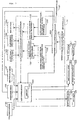
- FIG. 3 is a block diagram showing the configuration of the AMT control unit 18 and its peripheral equipment according to this preferred embodiment.
- the AMT control unit 18 includes a shift control section 100 storing a shift map 101.
- the shift control section 100 including clutch control means drives the shift control motor 25 and the valve 42 (42a or 42b) by using the shift map 101 such as a three-dimensional map according to output information from a gear position sensor 38, engine speed sensor 36, and throttle angle sensor 47 and vehicle speed information from a vehicle speed sensor 181 during normal running of the vehicle, thus performing a shift operation. Further, at starting the vehicle, the shift control section 100 performs clutch engagement control including partial clutch engagement control, so as to attain smooth transmission of engine torque.
- the shift control section 100 can detect a shift condition such as a condition where the transmission 21 is being shifted according to a shift signal generated in the automatic shifting mode using the shift map 101 or in the semiautomatic shifting mode by the operation of the shift select switch 50. Further, the shift control section 100 always detects a control current value supplied to the valve 42, or a clutch control amount in driving the clutch.
- the AMT control unit 18 can detect the timing at which the drive wheel actually starts rotating and can detect the clutch control amount at this timing. Further, the AMT control unit 18 can calculate a control correction amount according to this clutch control amount to correct this clutch control amount. According to such clutch correction control, the clutch control amount can be increased even when friction in a driving force transmitting system is increased due to aged deterioration or the like or when the clutch plates are worn to cause an increase in invalid stroke of the clutch plates until they come into contact with each other, thereby preventing a change in starting and shifting feed. Further, even when there are variations in quality of the clutch, valve, etc. in manufacturing, a running feel can be made stable.
- the AMT control unit 18 includes drive wheel rotation start detecting means 160 for detecting that the drive wheel has started rotating and clutch control correction amount calculating means 110 for calculating the control correction amount according to the difference between the clutch control amount detected at starting the rotation of the drive wheel and a predetermined reference value.
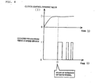
- the drive wheel rotation start detecting means 160 detects the timing of start of rotation of the drive wheel according to an output signal from the vehicle speed sensor 181 and temporarily stores the clutch control amount at this timing. This operation will now be described in more detail with reference to FIG. 4 .
- FIG. 4 is a graph showing the relation between counter pulses as an output signal from the vehicle speed sensor 181 and a clutch control current value. This graph corresponds to the case where the AMT 16 is switched from the neutral position (N) to the drive position (D) in the vehicle stopped condition and the clutch is next driven in its engaging direction according to a throttle operation. While the first clutch CL1 is engaged at starting with the first gear in this preferred embodiment, the second clutch CL2 may be engaged at starting with the second gear.
- the first clutch CL1 starts to be driven in its engaging direction according to the throttle operation by the operator, so that the clutch control current value as the clutch control amount starts to be raised.
- This time lag depends not only on the amount of invalid stroke which is generated from the time the clutch plates of the first clutch CL1 come into contact with each other and until the time a frictional force is generated, but also on the play of splines between the counter shaft 27 and the drive sprocket 35 (see FIG. 1 ), the slack or friction of the drive chain, the rotational resistance of the axle of the drive wheel, and the rolling friction of tires.
- a clutch oil pressure detected by the oil pressure sensor 75 or 76 may be adopted as the clutch control amount.
- the first counter pulse is output from the vehicle speed sensor 181 for outputting a counter pulse signal.
- the vehicle speed sensor 181 is adapted to directly detect the rotational speed of the drive wheel.
- the timing at which the first counter pulse from the vehicle speed sensor 181 is inverted after detection of the starting operation from the vehicle stopped condition is detected as the timing of start of rotation of the drive wheel.
- the vehicle speed sensor 181 is composed of a pulser ring (not shown) as a sensed element formed with a plurality of projections and depressions and a noncontact type sensor for detecting the passing state of these projections and depressions of the pulser ring rotating together with the drive wheel.
- the drive wheel rotation start detecting means 160 temporarily stores a clutch control current value It detected at starting of rotation of the drive wheel.
- the drive wheel rotation start detecting means 160 calculates the difference between the clutch control current value It temporarily stored and a reference current value stored in reference current value storing means 170 and transmits this difference to target clutch capacity correction coefficient deriving means 120 and invalid stroke filling oil pressure deriving means 140.
- the target clutch capacity correction coefficient deriving means 120 applies the difference between the clutch control current value It and the reference current value to a clutch control value - target clutch capacity correction coefficient table 130, thereby deriving a target clutch capacity correction coefficient.
- the target clutch capacity means a target value for the maximum engine torque that can be transmitted by the clutch, wherein the target value is calculated according to various parameters.
- the shift control section 100 calculates a target clutch pressure according to this target clutch capacity and supplies a control current generating this target clutch pressure to the valve 42.
- the invalid stroke filling oil pressure deriving means 140 applies the difference between the clutch control current value It and the reference current value to a clutch control current value - invalid stroke filling oil pressure table 150, thereby deriving an invalid stroke filling oil pressure.
- the invalid stroke means the amount of movement of the clutch plates from the initial position where no oil pressure is supplied to the clutch to the operational position where the clutch plates come into contact with each other. This invalid stroke increases because of the wear of the clutch plates, for example, causing a response delay in the clutch engagement control.
- the invalid stroke filling oil pressure is set to be supplied as a preload to the clutch, thereby shifting the initial position of the clutch toward the operational position. As a result, the invalid stroke can be reduced (filled). This operation will now be described in more detail with reference to FIG. 5 .
- FIG. 5 is a block diagram showing the flow of the clutch correction control by two methods according to the clutch control current value It detected at starting of rotation of the drive wheel.
- the clutch control current value It at starting of rotation of the drive wheel is detected (E1).
- the clutch control current value Is (E4) calculated above is next applied to a clutch control current value Is - target clutch capacity correction coefficient H table, thereby deriving a target clutch capacity correction coefficient H (E5). Simultaneously, the clutch control current value Is is also applied to a clutch control current value Is - invalid stroke filling oil pressure P table, thereby deriving an invalid stroke filling oil pressure P (E7).
- the target clutch capacity correction coefficient H is used mainly for the correction of clutch control during running (E6), and this correction coefficient H has an effect on the magnitude of a clutch pressure for transmitting engine torque and variations in clutch pressure upon shifting.
- the invalid stroke filling oil pressure P is used mainly for the correction of invalid stroke filling clutch control at starting (E8). This oil pressure P has an effect on the time period from the timing of start of driving of the clutch in its disengaged condition to the timing of contact of the clutch plates.
- the clutch control correction amount to be applied during running and the clutch control correction amount to be applied at starting can be calculated individually according to the clutch control current value Is detected at starting of rotation of the drive wheel.
- the control of supplying a preload to the clutch by using the invalid stroke filling oil pressure P may be performed when the neutral position (N) is switched to the drive position (D) by the neutral select switch 51 (see FIG. 1 ) after starting the drive source in the vehicle.
- invalid stroke filling control it is possible to eliminate a time lag from the timing of detection of a starting operation to the timing of generation of a frictional force in the clutch even when the invalid stroke is increased due to the wear of the clutch plates. As a result, a running feel can be made stable.
- the target clutch capacity correction coefficient H calculated by the target clutch capacity correction coefficient deriving means 120 and the invalid stroke filling oil pressure P calculated by the invalid stroke filling oil pressure deriving means 140 are input into the clutch control correction amount calculating means 110.
- the clutch control correction amount calculating means 110 uses both the target clutch capacity correction coefficient H and the invalid stroke filling oil pressure P to calculate two control correction amounts and transmit them to the shift control section 100.
- the shift control section 100 drives the valve 42 according to these two control correction amounts.
- Output signals from inclination angle detecting means 182 and brake operation detecting means 183 are input into the clutch control correction amount calculating means 110.
- the inclination angle detecting means 182 includes a pendulum always pointed downward in a vertical direction, a case for holding the pendulum, and a sensor for detecting a relative angle between the pendulum and the case, wherein an inclination angle of the vehicle body in its longitudinal direction is detected according to an output signal from the sensor.
- the brake operation detecting means 183 is configured to detect whether or not a brake operation has been performed according to information from a brake lamp switch or a braking pressure sensor (both not shown).
- the clutch control correction amount calculating means 110 is connected to warning means 200 for giving a warning to the operator when predetermined conditions are satisfied.
- FIG. 6 is a block diagram showing the procedure of calculating the clutch control correction amount applied during running by using the target clutch capacity correction coefficient H.
- a target clutch capacity C is calculated according to engine torque or the like generated during running.
- a target clutch capacity correction coefficient H as a correction coefficient for the target clutch capacity C is calculated in the target clutch capacity correction coefficient deriving means 120 (see FIG. 3 ).
- a value obtained by the expression of reference friction coefficient u0 ⁇ oil temperature correction value (block F3) is multiplied by a predetermined ⁇ correction coefficient (block F4) to thereby calculate a corrected friction coefficient ⁇ h.
- a target clutch pressure P is calculated by using the target clutch capacity C, the target clutch capacity correction coefficient H, and the corrected friction coefficient ⁇ h. As shown in block F6, the target clutch pressure P is obtained by the expression of ⁇ (C ⁇ H/ ⁇ h ⁇ the number of clutch plates ⁇ effective radius) + return spring load ⁇ /pressure receiving area of clutch piston.
- the target clutch pressure P is applied to a target clutch pressure P - clutch control current value I table to thereby derive a corrected clutch control current value I in block F8.
- the corrected clutch control current value I is applicable not only to the clutch control upon shifting during running, but also to the partial clutch engagement control at starting.
- target clutch capacity correction coefficient H is obtained according to the difference between the clutch control amount detected at starting of rotation of the drive wheel and the reference value in this preferred embodiment, a correction coefficient for the target clutch pressure P may be obtained instead.
- FIG. 7 is a flowchart showing the flow of clutch control correction amount calculation processing. This flowchart corresponds to the flow of the correction control procedure shown in FIG. 5 .
- step S1 it is determined whether or not a starting operation is detected in the vehicle stopped condition. If the answer in step S1 is affirmative, the program proceeds to step S2.
- the starting operation by the operator can be detected when the neutral position (N) is switched to the drive position (D) by the neutral select switch 51 and the engine speed starts to be increased by the throttle operation. Further, the vehicle stopped condition can be detected according to an output signal from the vehicle speed sensor 181.
- step S2 it is determined whether or not an output pulse from the vehicle speed sensor 181 is detected. If the answer in step S2 is affirmative, the program proceeds to step S3. If the answer in step S2 is negative, the program returns to step S2. If the answer in step S1 is negative, the program is ended because this case is a vehicle running condition, for example, and is not suitable for the calculation of a control correction amount.
- step S3 it is determined whether or not the vehicle is inclined in its longitudinal direction, i.e., whether or not the road surface on which the vehicle is at rest is sloping, by the inclination angle detecting means 182 (see FIG. 3 ). If the answer in step S3 is affirmative, the program is ended because this case is a starting condition on an upward or downward slope and is not suitable for the calculation of a control correction amount. If the answer in step S3 is negative, the program proceeds to step S4 to determine whether or not a brake operation is performed by the brake operation detecting means 183. If the answer in step S4 is affirmative, the program is ended because this case is a condition where a braking force is applied to the vehicle and is not suitable for the calculation of a control correction amount.
- step S5 a target clutch capacity correction coefficient is derived by the target clutch capacity correction coefficient deriving means 120 (see FIG. 3 ) according to the clutch control current value detected upon detection of the counter pulse from the vehicle speed sensor 181, i.e., at starting of rotation of the drive wheel.
- step S6 an invalid stroke filling oil pressure is derived by the invalid stroke filling oil pressure deriving means 140 according to the clutch control current value detected upon detection of the counter pulse.
- a clutch control correction amount is calculated by the clutch control amount calculating means 110 by using the target clutch capacity correction coefficient and the invalud stroke filling oil pressure. Thereafter, the program is ended.
- the calculation of the clutch control correction amount may be performed according to the average of amounts of movement of the vehicle after making a plurality of detections of the clutch control amount at starting of rotation of the drive wheel. Accordingly, even when the clutch control amount at starting of rotation of the drive wheel is suddenly varied due to uneveness or gravel on a road surface, the influence by such variations in clutch control amount can be eliminated.
- this clutch control amount detected at starting of rotation of the drive wheel exceeds a predetermined value, this clutch control amount is not applied to the control correction amount calculation processing shown in FIG. 7 and a warning can be given to the operator by the warning means 200 such as a warning lamp or a speaker. Accordingly, it is possible to urge the operator to check the wear of the clutch plates, the degradation of engine oil, and any abnormality in the power transmitting system from the clutch to the drive wheel.
- control correction amount calculation processing can be applied not only to the correction for the bad engaged condition of the clutch due to aged deterioration or the like, but also to initial setting prior to shipment of the vehicle from a factory. In this case, variations in accuracy of the valve and the clutch can be absorbed to unify the clutch settings.
- the control correction amount calculation processing may be suspended. Accordingly, the conditions upon detection of the clutch control amount can be made stable to execute proper operational processing. In the case that the various conditions mentioned above are satisfied to suspend the calculation of the control correction amount, the clutch control amount may be decided according to the control correction amount already calculated.
- the clutch control amount at starting of rotation of the drive wheel of the vehicle after driving the clutch in its engaging direction is detected, and the clutch control amount is corrected according to this control amount detected above. Accordingly, even when the clutch control amount at starting of rotation of the drive wheel is varied due to variations in quality of the clutch in manufacturing or an increase in friction in the driving force transmitting system, the clutch control can be performed by applying a control correction amount according to the above variations in clutch control amount. As a result, a shifting feel at starting or during running can be made stable.
- the configuration of the clutch and the valve, the configuration of the vehicle speed sensor, the configuration of the clutch control current value - target clutch capacity correction coefficient table and the clutch control current value - invalid stroke filling oil pressure table, the setting of the reference clutch control current value, the calculation method for the target clutch pressure, the detection method for the starting operation, for example, are not limited to those described above in this preferred embodiment, but various modifications may be made.
- the clutch control device according to the present invention is applicable not only to a motorcycle, but also to a three-wheel vehicle and a four-wheel vehicle, for example.
- Engine power source
- 16 AMT 18: AMT control unit
- 25 Shift control motor
- 26 Main shaft
- 26a Inner main shaft
- 26b Outer main shaft
- 27 Counter shaft
- 36 Engine speed sensor
- 42 Valve
- 42a First valve
- 42b Second valve
- 47 Throttle angle sensor
- 100 Shift control section (clutch control means)
- 101 Shift map
- 110 Clutch control correction amount calculating means
- 120 Target clutch capacity correction coefficient deriving means
- 140 Invalid stroke filling oil pressure deriving means
- 160 Drive wheel rotation start detecting means
- 170 Reference current value storing means
- 181 Vehicle speed sensor
- M1 to M6 First to sixth drive gear
- C1 to C6 First to sixth driven gear
- CL1 First clutch
- CL2 Second clutch.
Landscapes
- Engineering & Computer Science (AREA)
- General Engineering & Computer Science (AREA)
- Physics & Mathematics (AREA)
- Fluid Mechanics (AREA)
- Mechanical Engineering (AREA)
- Hydraulic Clutches, Magnetic Clutches, Fluid Clutches, And Fluid Joints (AREA)
- Mechanical Operated Clutches (AREA)
Claims (9)
- Kupplungssteuerungsvorrichtung für eine Kupplung, um die Übertragung einer Rotationsantriebskraft von einer Antriebsquelle (11) auf ein Antriebsrad in einem Fahrzeug durch eine Verbindung herzustellen und die Verbindung zu lösen, wobei die Kupplungssteuerungsvorrichtung aufweist:Kupplungssteuerungsmittel (100), um einen Steuerungsbetrag für die Kupplung zu steuern;Mittel (160) zum Erfassen des Beginns der Rotation des Antriebsrads, um basierend auf dem Fahrzeuggeschwindigkeitssensor (181) den Beginn der Rotation des Antriebsrads zu erfassen, um eine Rotationsgeschwindigkeit des Antriebsrads direkt zu erfassen; undMittel zum Berechnen des Steuerungskorrekturbetrags, um einen Steuerungskorrekturbetrag für die Kupplung gemäß der Differenz zwischen dem beim Start der Rotation des Antriebsrads erfassten Kupplungssteuerungsbetrag und einem vorbestimmten Referenzwert zu berechnen;wobei das Kupplungssteuerungsmittel (100) den Steuerungskorrekturbetrag auf den Steuerungsbetrag für die Kupplung anwendet, um dadurch die Kupplung zu steuern,dadurch gekennzeichnet, dassdas Mittel zum Berechnen des Steuerungskorrekturbetrags einen Steuerungskorrekturbetrag berechnet, der auf die Kupplungssteuerung während der Fahrt eines Fahrzeugs angewendet wird, und ein Steuerungskorrekturbetrag, der auf eine ungültige Hubauffüllsteuerung beim Start des Fahrzeugs angewendet wird.
- Kupplungssteuerungsvorrichtung nach Anspruch 1, wobei das Mittel (160) zum Erfassen des Beginns der Rotation des Antriebsrads den Beginn der Rotation aus dem angehaltenen Zustand des Antriebsrads gemäß eines Ausgabepulses von dem Fahrzeuggeschwindigkeitssensor (181) erfasst, um eine Rotationsgeschwindigkeit des Antriebsrads direkt zu erfassen.
- Kupplungssteuerungsvorrichtung nach einem der Ansprüche 1 bis 2, die weiterhin aufweist
Mittel zum Erfassen eines Neigungswinkels, um einen Neigungswinkel des Fahrzeugs in der Längsrichtung zu erfassen,
wobei, wenn der Neigungswinkel größer als ein vorbestimmter Wert ist, das Mittel zum Berechnen des Steuerungskorrekturbetrags die Berechnung des Steuerungskorrekturbetrags anhält. - Kupplungssteuerungsvorrichtung nach einem der vorhergehenden Ansprüche, die weiterhin aufweist
Mittel zum Erfassen eines Bremsvorgangs, um einen Bremsvorgang in dem Fahrzeug zu erfassen, wobei bei Erfassen des Bremsvorgangs das Mittel zum Berechnen der Steuerungskorrekturbetrags die Berechnung des Steuerungskorrekturbetrags anhält. - Kupplungssteuerungsvorrichtung nach einem der vorhergehenden Ansprüche, wobei die Kupplung eine Kupplung des Doppelkupplungstyps ist, die aus einer ersten Kupplung (CL1) und einer zweiten Kupplung (CL2) besteht, die an einer Hauptwelle (26) vorgesehen ist;
der Eingriffszustand der ersten Kupplung (CL1) und der Eingriffszustand der zweiten Kupplung (CL2) abwechselnd jedes Mal gewechselt werden, wenn eine Schaltoperation durchgeführt wird, wodurch die Rotationsantriebskraft von der Antriebsquelle (11) auf das Antriebsrad übertragen wird. - Kupplungssteuerungsvorrichtung nach einem der vorhergehenden Ansprüche, wobei die Berechnung des Kupplungssteuerungskorrekturbetrags gemäß einem Durchschnitt der Beträge der Bewegungen des Fahrzeugs durchgeführt wird, nachdem eine Vielzahl von Erfassungen des Kupplungssteuerungsbetrags bei Beginn der Rotation des Antriebsrads durchgeführt wurden.
- Kupplungssteuerungsvorrichtung nach einem der vorhergehenden Ansprüche, die weiterhin aufweist
Warnmittel, um eine Warnung auszugeben, wobei wenn der Steuerungskorrekturbetrag einen bestimmten Wert übersteigt, das Mittel zum Berechnen des Steuerungskorrekturbetrags die Warnung über die Warnmittel ausgibt. - Kupplungssteuerungsvorrichtung nach einem der vorhergehenden Ansprüche, wobei die Kupplung durch einen Aktuator angetrieben wird und der Steuerungsbetrag für die Kupplung ein Steuerungsstromwert ist, der dem Aktuator zugeführt wird.
- Kupplungssteuerungsvorrichtung nach einem der vorhergehenden Ansprüche, wobei die Kupplung eine Hydraulikkupplung ist, und der Steuerungsbetrag für die Kupplung ein Öldruck ist, der in der Kupplung erzeugt wird.
Applications Claiming Priority (1)
| Application Number | Priority Date | Filing Date | Title |
|---|---|---|---|
| JP2008137982A JP5200272B2 (ja) | 2008-05-27 | 2008-05-27 | クラッチ制御装置 |
Publications (2)
| Publication Number | Publication Date |
|---|---|
| EP2128472A1 EP2128472A1 (de) | 2009-12-02 |
| EP2128472B1 true EP2128472B1 (de) | 2018-10-17 |
Family
ID=40852162
Family Applications (1)
| Application Number | Title | Priority Date | Filing Date |
|---|---|---|---|
| EP09155587.0A Active EP2128472B1 (de) | 2008-05-27 | 2009-03-19 | Vorrichtung zur Kupplungssteuerung |
Country Status (3)
| Country | Link |
|---|---|
| US (1) | US8788169B2 (de) |
| EP (1) | EP2128472B1 (de) |
| JP (1) | JP5200272B2 (de) |
Families Citing this family (16)
| Publication number | Priority date | Publication date | Assignee | Title |
|---|---|---|---|---|
| JP5374726B2 (ja) * | 2008-03-31 | 2013-12-25 | 本田技研工業株式会社 | クラッチ制御装置およびμ補正係数算出方法 |
| JP5153525B2 (ja) * | 2008-09-01 | 2013-02-27 | 本田技研工業株式会社 | クラッチ制御装置 |
| JP5340978B2 (ja) * | 2010-02-03 | 2013-11-13 | 本田技研工業株式会社 | 変速制御装置 |
| JP5425660B2 (ja) * | 2010-02-23 | 2014-02-26 | 本田技研工業株式会社 | 変速段表示装置 |
| DE112011101096B4 (de) | 2010-04-01 | 2023-02-02 | Schaeffler Technologies AG & Co. KG | Verfahren zum betreiben einer doppelkupplung |
| JP5589531B2 (ja) * | 2010-04-23 | 2014-09-17 | トヨタ自動車株式会社 | 車両用油圧制御装置 |
| JP2012051385A (ja) * | 2010-08-31 | 2012-03-15 | Hitachi Ltd | 移動機構 |
| US9926988B2 (en) * | 2013-01-17 | 2018-03-27 | Nissan Motor Co., Ltd. | Starting clutch control device for automatic transmission |
| JP6283641B2 (ja) | 2015-09-30 | 2018-02-21 | 本田技研工業株式会社 | 自動クラッチ車両 |
| KR101717713B1 (ko) * | 2015-10-05 | 2017-03-17 | 현대위아(주) | 차량용 다판 클러치의 예압량 결정 시스템 |
| JP6728803B2 (ja) * | 2016-03-14 | 2020-07-22 | 株式会社ジェイテクト | 駆動力伝達装置の制御装置及び制御方法 |
| JP6782657B2 (ja) | 2017-03-29 | 2020-11-11 | 本田技研工業株式会社 | クラッチ制御装置 |
| DE102017218669A1 (de) * | 2017-10-19 | 2019-04-25 | Robert Bosch Gmbh | Verfahren und Vorrichtung zum Betreiben eines teil- oder vollautonom fahrbaren Kraftfahrzeugs |
| TWI682871B (zh) | 2018-08-28 | 2020-01-21 | 財團法人工業技術研究院 | 變速控制系統 |
| JP7667874B2 (ja) | 2021-11-23 | 2025-04-23 | ロベルト・ボッシュ・ゲゼルシャフト・ミト・ベシュレンクテル・ハフツング | 制御装置及び制御方法 |
| CN117804796B (zh) * | 2024-01-17 | 2024-12-13 | 北京理工大学 | 一种数字孪生驱动的离合器性能监测与评估系统 |
Family Cites Families (20)
| Publication number | Priority date | Publication date | Assignee | Title |
|---|---|---|---|---|
| JPH0826901B2 (ja) * | 1987-10-31 | 1996-03-21 | いすゞ自動車株式会社 | クラッチ制御装置 |
| JPH03234925A (ja) * | 1990-02-07 | 1991-10-18 | Hino Motors Ltd | 油圧クラッチの発進制御装置 |
| JP2968563B2 (ja) * | 1990-06-18 | 1999-10-25 | マツダ株式会社 | 自動クラッチ式変速機の制御装置 |
| JPH09112589A (ja) * | 1995-10-18 | 1997-05-02 | Isuzu Motors Ltd | オートクラッチ制御装置 |
| JPH1193973A (ja) * | 1997-09-24 | 1999-04-06 | Mitsubishi Motors Corp | 車両のクラッチ摩耗検出装置 |
| JPH11166559A (ja) * | 1997-12-08 | 1999-06-22 | Unisia Jecs Corp | 車両用自動クラッチ制御装置 |
| JP3536658B2 (ja) * | 1998-03-31 | 2004-06-14 | 日産自動車株式会社 | ハイブリッド車両の駆動制御装置 |
| DE19826059B4 (de) * | 1998-06-12 | 2006-04-06 | Zf Friedrichshafen Ag | Verfahren zum Steuern eines Automatgetriebes |
| JP2000110856A (ja) * | 1998-09-30 | 2000-04-18 | Suzuki Motor Corp | クラッチのクリープ制御装置 |
| DE10139122A1 (de) * | 2000-09-08 | 2002-03-21 | Luk Lamellen & Kupplungsbau | Steuergeräteanordnung und Verfahren zur Steuerung von Antriebsstrangbauteilen |
| FR2828450B1 (fr) * | 2001-08-07 | 2003-10-03 | Renault | Dispositif d'assistance au demarrage en cote pour vehicule automobile |
| JP2004197842A (ja) | 2002-12-18 | 2004-07-15 | Aisin Seiki Co Ltd | クラッチ制御装置 |
| JP4394386B2 (ja) * | 2003-07-07 | 2010-01-06 | アイシン精機株式会社 | クラッチ制御装置 |
| JP4411988B2 (ja) * | 2004-01-30 | 2010-02-10 | アイシン精機株式会社 | クラッチ制御装置 |
| JP4747684B2 (ja) * | 2005-06-06 | 2011-08-17 | 日産自動車株式会社 | 車両の発進クラッチ制御装置 |
| EP1762452A3 (de) * | 2005-09-08 | 2009-05-27 | Nissan Motor Co., Ltd. | Motorstartsteuerung und Verfahren |
| JP4937569B2 (ja) * | 2005-11-21 | 2012-05-23 | 三菱ふそうトラック・バス株式会社 | 自動クラッチ制御装置 |
| CN101321965B (zh) * | 2005-11-29 | 2010-08-11 | 罗伯特·博世有限公司 | 设有摩擦式无级变速器的车辆传动系的离合器控制方法 |
| DE102006037389A1 (de) * | 2006-08-10 | 2008-02-14 | Daimler Ag | Verfahren zur Abschätzung einer an einer Anfahrkupplung eines Kraftfahrzeugs dissipierten Energiemenge |
| JP5189337B2 (ja) * | 2007-09-27 | 2013-04-24 | 本田技研工業株式会社 | 鞍乗型車両のクラッチ制御システム |
-
2008
- 2008-05-27 JP JP2008137982A patent/JP5200272B2/ja active Active
-
2009
- 2009-03-19 EP EP09155587.0A patent/EP2128472B1/de active Active
- 2009-04-30 US US12/433,102 patent/US8788169B2/en active Active
Non-Patent Citations (1)
| Title |
|---|
| None * |
Also Published As
| Publication number | Publication date |
|---|---|
| US8788169B2 (en) | 2014-07-22 |
| US20090299590A1 (en) | 2009-12-03 |
| JP2009287606A (ja) | 2009-12-10 |
| JP5200272B2 (ja) | 2013-06-05 |
| EP2128472A1 (de) | 2009-12-02 |
Similar Documents
| Publication | Publication Date | Title |
|---|---|---|
| EP2128472B1 (de) | Vorrichtung zur Kupplungssteuerung | |
| EP2159440B1 (de) | Kupplungssteuerungsvorrichtung und Verfahren zur Berechnung der Korrekturmenge einer Kupplungssteuerung | |
| CN101981337B (zh) | 离合器控制装置及μ修正系数计算方法 | |
| US7935016B2 (en) | Automatic transmission | |
| US9303752B2 (en) | Shift change controlling apparatus | |
| US9032824B2 (en) | Control device for dual clutch transmission and control method for dual clutch transmission | |
| US20120298466A1 (en) | Clutch control device | |
| US9051975B2 (en) | Dual clutch transmission mechanism and start control method | |
| CN102149947A (zh) | 用于自动变速器内的可选择的单向离合器或机械二极管的发动机动力管理 | |
| US8768589B2 (en) | Control device for dual clutch transmission and control method for dual clutch transmission | |
| US8287432B2 (en) | Clutch control system for transmission | |
| US9346453B2 (en) | Transmission device | |
| CN104806747B (zh) | 离合器压力控制装置 | |
| WO2013161698A1 (ja) | 自動変速機の制御装置 | |
| EP3505786B1 (de) | Kupplungssteuerungsvorrichtung | |
| US20080182715A1 (en) | Automotive-transmission clutch-pressure duration | |
| US20170268665A1 (en) | Control apparatus and method of automatic transmission |
Legal Events
| Date | Code | Title | Description |
|---|---|---|---|
| PUAI | Public reference made under article 153(3) epc to a published international application that has entered the european phase |
Free format text: ORIGINAL CODE: 0009012 |
|
| 17P | Request for examination filed |
Effective date: 20090319 |
|
| AK | Designated contracting states |
Kind code of ref document: A1 Designated state(s): AT BE BG CH CY CZ DE DK EE ES FI FR GB GR HR HU IE IS IT LI LT LU LV MC MK MT NL NO PL PT RO SE SI SK TR |
|
| AX | Request for extension of the european patent |
Extension state: AL BA RS |
|
| AKX | Designation fees paid |
Designated state(s): DE FR IT |
|
| 17Q | First examination report despatched |
Effective date: 20121022 |
|
| STAA | Information on the status of an ep patent application or granted ep patent |
Free format text: STATUS: EXAMINATION IS IN PROGRESS |
|
| GRAP | Despatch of communication of intention to grant a patent |
Free format text: ORIGINAL CODE: EPIDOSNIGR1 |
|
| STAA | Information on the status of an ep patent application or granted ep patent |
Free format text: STATUS: GRANT OF PATENT IS INTENDED |
|
| INTG | Intention to grant announced |
Effective date: 20180619 |
|
| GRAS | Grant fee paid |
Free format text: ORIGINAL CODE: EPIDOSNIGR3 |
|
| GRAA | (expected) grant |
Free format text: ORIGINAL CODE: 0009210 |
|
| STAA | Information on the status of an ep patent application or granted ep patent |
Free format text: STATUS: THE PATENT HAS BEEN GRANTED |
|
| AK | Designated contracting states |
Kind code of ref document: B1 Designated state(s): DE FR IT |
|
| REG | Reference to a national code |
Ref country code: DE Ref legal event code: R096 Ref document number: 602009055072 Country of ref document: DE |
|
| PGFP | Annual fee paid to national office [announced via postgrant information from national office to epo] |
Ref country code: GB Payment date: 20190116 Year of fee payment: 14 Ref country code: IT Payment date: 20190321 Year of fee payment: 11 |
|
| REG | Reference to a national code |
Ref country code: DE Ref legal event code: R097 Ref document number: 602009055072 Country of ref document: DE |
|
| PLBE | No opposition filed within time limit |
Free format text: ORIGINAL CODE: 0009261 |
|
| STAA | Information on the status of an ep patent application or granted ep patent |
Free format text: STATUS: NO OPPOSITION FILED WITHIN TIME LIMIT |
|
| 26N | No opposition filed |
Effective date: 20190718 |
|
| REG | Reference to a national code |
Ref country code: DE Ref legal event code: R084 Ref document number: 602009055072 Country of ref document: DE |
|
| PG25 | Lapsed in a contracting state [announced via postgrant information from national office to epo] |
Ref country code: FR Free format text: LAPSE BECAUSE OF NON-PAYMENT OF DUE FEES Effective date: 20200331 |
|
| PG25 | Lapsed in a contracting state [announced via postgrant information from national office to epo] |
Ref country code: IT Free format text: LAPSE BECAUSE OF NON-PAYMENT OF DUE FEES Effective date: 20200319 |
|
| PGFP | Annual fee paid to national office [announced via postgrant information from national office to epo] |
Ref country code: DE Payment date: 20260219 Year of fee payment: 18 |