EP2086692B1 - Dispositif d'encollage - Google Patents
Dispositif d'encollage Download PDFInfo
- Publication number
- EP2086692B1 EP2086692B1 EP07846504.4A EP07846504A EP2086692B1 EP 2086692 B1 EP2086692 B1 EP 2086692B1 EP 07846504 A EP07846504 A EP 07846504A EP 2086692 B1 EP2086692 B1 EP 2086692B1
- Authority
- EP
- European Patent Office
- Prior art keywords
- glue
- scraper
- roller
- accordance
- mount
- Prior art date
- Legal status (The legal status is an assumption and is not a legal conclusion. Google has not performed a legal analysis and makes no representation as to the accuracy of the status listed.)
- Active
Links
- 239000003292 glue Substances 0.000 title claims description 170
- 238000004026 adhesive bonding Methods 0.000 claims description 21
- 238000002372 labelling Methods 0.000 claims description 12
- 238000003825 pressing Methods 0.000 claims description 4
- 229910001369 Brass Inorganic materials 0.000 claims description 2
- 239000010951 brass Substances 0.000 claims description 2
- 238000000151 deposition Methods 0.000 claims 3
- 238000011144 upstream manufacturing Methods 0.000 claims 1
- 230000002093 peripheral effect Effects 0.000 description 14
- 238000009826 distribution Methods 0.000 description 11
- 238000011109 contamination Methods 0.000 description 3
- 239000000463 material Substances 0.000 description 2
- 239000004831 Hot glue Substances 0.000 description 1
- 229910000639 Spring steel Inorganic materials 0.000 description 1
- 230000015572 biosynthetic process Effects 0.000 description 1
- 239000011111 cardboard Substances 0.000 description 1
- 239000011248 coating agent Substances 0.000 description 1
- 238000000576 coating method Methods 0.000 description 1
- 238000005520 cutting process Methods 0.000 description 1
- 230000006735 deficit Effects 0.000 description 1
- 230000001419 dependent effect Effects 0.000 description 1
- 238000011161 development Methods 0.000 description 1
- 230000018109 developmental process Effects 0.000 description 1
- 230000009760 functional impairment Effects 0.000 description 1
- 238000010380 label transfer Methods 0.000 description 1
- 230000007257 malfunction Effects 0.000 description 1
- 238000004519 manufacturing process Methods 0.000 description 1
- 210000000056 organ Anatomy 0.000 description 1
- 239000011087 paperboard Substances 0.000 description 1
- 238000003860 storage Methods 0.000 description 1
- 239000000126 substance Substances 0.000 description 1
Images


Classifications
-
- B—PERFORMING OPERATIONS; TRANSPORTING
- B05—SPRAYING OR ATOMISING IN GENERAL; APPLYING FLUENT MATERIALS TO SURFACES, IN GENERAL
- B05C—APPARATUS FOR APPLYING FLUENT MATERIALS TO SURFACES, IN GENERAL
- B05C1/00—Apparatus in which liquid or other fluent material is applied to the surface of the work by contact with a member carrying the liquid or other fluent material, e.g. a porous member loaded with a liquid to be applied as a coating
- B05C1/04—Apparatus in which liquid or other fluent material is applied to the surface of the work by contact with a member carrying the liquid or other fluent material, e.g. a porous member loaded with a liquid to be applied as a coating for applying liquid or other fluent material to work of indefinite length
- B05C1/08—Apparatus in which liquid or other fluent material is applied to the surface of the work by contact with a member carrying the liquid or other fluent material, e.g. a porous member loaded with a liquid to be applied as a coating for applying liquid or other fluent material to work of indefinite length using a roller or other rotating member which contacts the work along a generating line
- B05C1/0817—Apparatus in which liquid or other fluent material is applied to the surface of the work by contact with a member carrying the liquid or other fluent material, e.g. a porous member loaded with a liquid to be applied as a coating for applying liquid or other fluent material to work of indefinite length using a roller or other rotating member which contacts the work along a generating line characterised by means for removing partially liquid or other fluent material from the roller, e.g. scrapers
-
- B—PERFORMING OPERATIONS; TRANSPORTING
- B05—SPRAYING OR ATOMISING IN GENERAL; APPLYING FLUENT MATERIALS TO SURFACES, IN GENERAL
- B05C—APPARATUS FOR APPLYING FLUENT MATERIALS TO SURFACES, IN GENERAL
- B05C11/00—Component parts, details or accessories not specifically provided for in groups B05C1/00 - B05C9/00
- B05C11/02—Apparatus for spreading or distributing liquids or other fluent materials already applied to a surface ; Controlling means therefor; Control of the thickness of a coating by spreading or distributing liquids or other fluent materials already applied to the coated surface
- B05C11/04—Apparatus for spreading or distributing liquids or other fluent materials already applied to a surface ; Controlling means therefor; Control of the thickness of a coating by spreading or distributing liquids or other fluent materials already applied to the coated surface with blades
- B05C11/041—Apparatus for spreading or distributing liquids or other fluent materials already applied to a surface ; Controlling means therefor; Control of the thickness of a coating by spreading or distributing liquids or other fluent materials already applied to the coated surface with blades characterised by means for positioning, loading, or deforming the blades
-
- B—PERFORMING OPERATIONS; TRANSPORTING
- B05—SPRAYING OR ATOMISING IN GENERAL; APPLYING FLUENT MATERIALS TO SURFACES, IN GENERAL
- B05C—APPARATUS FOR APPLYING FLUENT MATERIALS TO SURFACES, IN GENERAL
- B05C11/00—Component parts, details or accessories not specifically provided for in groups B05C1/00 - B05C9/00
- B05C11/02—Apparatus for spreading or distributing liquids or other fluent materials already applied to a surface ; Controlling means therefor; Control of the thickness of a coating by spreading or distributing liquids or other fluent materials already applied to the coated surface
- B05C11/04—Apparatus for spreading or distributing liquids or other fluent materials already applied to a surface ; Controlling means therefor; Control of the thickness of a coating by spreading or distributing liquids or other fluent materials already applied to the coated surface with blades
- B05C11/048—Scrapers, i.e. metering blades having their edge oriented in the upstream direction in order to provide a reverse angle of attack
-
- B—PERFORMING OPERATIONS; TRANSPORTING
- B65—CONVEYING; PACKING; STORING; HANDLING THIN OR FILAMENTARY MATERIAL
- B65C—LABELLING OR TAGGING MACHINES, APPARATUS, OR PROCESSES
- B65C9/00—Details of labelling machines or apparatus
- B65C9/20—Gluing the labels or articles
- B65C9/22—Gluing the labels or articles by wetting, e.g. by applying liquid glue or a liquid to a dry glue coating
- B65C9/2247—Gluing the labels or articles by wetting, e.g. by applying liquid glue or a liquid to a dry glue coating using liquid rollers or bands
-
- B—PERFORMING OPERATIONS; TRANSPORTING
- B05—SPRAYING OR ATOMISING IN GENERAL; APPLYING FLUENT MATERIALS TO SURFACES, IN GENERAL
- B05C—APPARATUS FOR APPLYING FLUENT MATERIALS TO SURFACES, IN GENERAL
- B05C11/00—Component parts, details or accessories not specifically provided for in groups B05C1/00 - B05C9/00
- B05C11/02—Apparatus for spreading or distributing liquids or other fluent materials already applied to a surface ; Controlling means therefor; Control of the thickness of a coating by spreading or distributing liquids or other fluent materials already applied to the coated surface
- B05C11/04—Apparatus for spreading or distributing liquids or other fluent materials already applied to a surface ; Controlling means therefor; Control of the thickness of a coating by spreading or distributing liquids or other fluent materials already applied to the coated surface with blades
- B05C11/045—Apparatus for spreading or distributing liquids or other fluent materials already applied to a surface ; Controlling means therefor; Control of the thickness of a coating by spreading or distributing liquids or other fluent materials already applied to the coated surface with blades characterised by the blades themselves
Definitions
- the invention relates to a gluing device.
- This Beleimungsvorierien for use in labeling, z. B. in labeling of such machines.
- This Beleimungsvorierien consist essentially of a usually strip-like glue application and distribution element and a glue roller which is circumferentially driven around its roll axis and thereby moved past a glue delivery of the glue application and distribution element. This is done on the glue roller first a primary glue application, from which with a Leimwalzenburnlegischon the glue delivery glue scraper a uniform secondary glue application or glue film is generated, which is then transferred to the labels to be glued, either directly or indirectly by gluing Label pallets with which the labels are subsequently removed from a label magazine.
- the glue scraper is pivotally mounted and sprung by spring means or with a contact pressure generated by this spring means with a scraper or scraper on the peripheral surface of the glue roller.
- extensive devices for adjusting and / or aligning and / or adjusting the spring-mounted glue scraper are provided in known Beleimungsvorraumen.
- the disadvantage is, inter alia, that contamination of the elements for adjusting and / or aligning and / or adjusting the glue scraper and for springy storage, especially by glue and / or blended with the glue foreign substances is inevitable and these elements thereby their functionality completely or partially lose.
- a gluing device for use in labeling machines consisting, inter alia, of a glue roller, a glue application and distribution element for generating a primary glue application on the peripheral surface of the glue roller, from an in the direction of rotation of the glue roller on the glue applicator following glue bar, the production of the glue film with the required film thickness an exactly set distance from the circumference having the glue roller, as well as from a voltage applied to the glue roller and formed by a spring plate scraper, with the glue residues present on the glue roller are removed before each new glue application.
- a disadvantage of this known gluing device is, inter alia, that in order to achieve the desired glue film thickness, a very precise adjustment of the glue bar 9 is necessary and it also causes considerable malfunction due to the Peripheral surface of the glue roller existing foreign body, for example, by dried glue, label residues, etc. can come. Since the glue roller is subject to a closure on its peripheral surface, a time-consuming readjustment of the glue bar to maintain the required distance is also necessary.
- a gluing device in which the glue is applied to the glue roller via an applicator member in the form of a tube with a longitudinal slot.
- a glue scraper for the formation of the glue film from the primary glue application is not provided, only a spatula-like scraper on the tubular applicator organ, which is brought into labeling breaks for removing glue residues by pivoting the glue application member against the glue roller to the plant.
- gluing device according to the EP-A-0 571 849 , In the scope of interest here, this document relates to a device for coating running, consisting of paper or cardboard webs.
- the object of the invention is to show a use which avoids this disadvantage.
- a use according to the patent claim 1 is formed.
- the glue scraper or the scraper section abutting against the glue roller or a scraper element forming this scraper section is fastened or clamped exclusively by at least one spring element on the device-side glue scraper receptacle, ie it is held on this receptacle without joints.
- Spring Bearings consisting of rigid but adjustable bearings and independent spring elements for pressing the glue scraper against the glue roller 4 are completely avoided, so that the risk of contamination and the associated impairment of the functioning of the glue scraper or gluing device altogether do not exist.
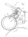
- 1 is a glue roller of a gluing or glue application device of a labeling unit of a machine, not shown, for labeling bottles or similar containers 2.
- the gluing device consists in a conventional manner of a substantially strip-shaped glue application and distribution element 3, from which a vertical roll axis driven peripherally Leimwalze 4, to be provided with the Etikettenleim (eg cold glue or hot glue) on the back and on the periphery of a Label transfer cylinder 5 (eg., Vacuum cylinder) held labels 2 or be moved to be glued label pallets, as is known in the art of labeling according to the prior art.
- Etikettenleim eg cold glue or hot glue
- a Label transfer cylinder 5 eg., Vacuum cylinder
- the glue application and distribution element 3 has a strip-like, with its longitudinal extent parallel to the axis of the glue roller 4 oriented housing 6, which forms a concave on one longitudinal side of the housing longitudinal axis bearing surface 7, with the glue application and distribution element 3 dense or largely tight against the circular cylindrical, the roller axis concentrically enclosing peripheral surface of the glue roller 4 is applied, and pressed by spring elements 8 a holder 9, with the glue application and distribution element to a machine frame of the gluing device 1 and the labeling unit is held.
- an open to this surface glue chamber 10 is formed, which communicates via a plurality of Leimausbergs- or manifold openings 11 and formed in a housing 6 distribution channel with a connection 12 in connection, which is in operation with facultyimbelungsvorutter 1 with a non is shown connected Leimpumpe.
- the groove-like glue chamber 10 is also oriented with its longitudinal axis parallel to the axis of the glue roller 4. About the glue chamber 10 takes place during operation of the gluing device, a gush-like primary glue application on the passing past the glue chamber 10 part of the peripheral surface of the glue roller 4, as shown in the FIG. 4 13 is exaggerated.
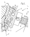
- a glue scraper 15 is provided, which is pressed against a strip-like, with its longitudinal extent parallel or at least approximately parallel to the axis of the glue roller 4 oriented scraper or scraper 16 pressed against the peripheral surface of the glue roller 4, in the direction of rotation A. the glue roller 4 on the glue chamber 10 following.
- the glue scraper 15 consists in the illustrated embodiment of the strip-shaped scraper element 16 and a strip-like, made of spring steel spring plate 17 which carries the scraper 16 on one longitudinal side and on the other longitudinal side in particular for positioning and aligning the scraper element 16 adjustable on the housing 6 and attached to a fastening or clamping surface 6.1 formed there.
- the scraper element 16 has an example rectangular cross section and is preferably with one of the two longer cross-sectional sides or with one of its edges against the peripheral surface of the glue roller 4 at.
- the spring plate 17 on the side facing away from the scraper 16 side several open to this longitudinal side recesses 18 for each engaging in a thread of the housing 6 clamping screw 19 and a terminal block 20, so that the spring plate 17 at its the scraper element 16th opposite side is held by clamping between the terminal block 20 and the clamping surface 6.1.
- the clamping surface 6.1, clamping screws 19 and terminal block 20 thus form an adjustable clamp or clamping 21.
- the clamping 21 forming the housing-side contact surface 6.1 lies in a plane that the Circumferential surface of the glue roller 4 at a cutting or surface line parallel to Leimwalzenachse intersects, in such a way that this plane E with the peripheral surface of the glue roller 4 an angle ⁇ less than 90 °, which opens in Leimwalzendreicardi A. Furthermore, the line of intersection between the plane of the contact surface 6.1 and the peripheral surface of the glue roller 4 in Leimwalzenwireutter A is following the doctor member 16.
- the scraper element 16 rests against the peripheral surface of the glue roller 4 with the contact force generated by the spring plate 17.
- the spring plate 17 is on its side facing away from the glue roller 3 or the housing 6 side facing concavely curved at least one axis extending in Fedel plate longitudinal axis. How the particular Figures 2 . 3 and 4 show, the clamping 21 of the spring plate 17 is provided so that it follows in the direction of rotation A of the glue roller 4 on the strip-like scraper element 16.
- the clamping 21 not only allows the glue scraper 15 to be aligned in such a way that the scraper element 16 is oriented with its longitudinal extension as exactly parallel to the axis of the glue roller 4 as possible, but with this clamping 21 the area at which the glue scraper 15 or 15 is also adjustable whose scraper element 16 abuts against the circumference of the glue roller 4, as shown in the FIG. 4 is indicated by the double arrow C.
- the contact pressure is variable, with which the scraper element 16 is pressed by acting as a leaf spring spring plate 17 against the glue roller 4, by changing the distance between the scraper element 16 and the clamping 21, on the other hand, the Area with which the scraper element 16 abuts linearly against the circumference of the glue roller 4.
- scraper element 16 is the line-shaped area 16.1 against the glue roller 4, in the vicinity of the rear side relative to the direction of rotation A longitudinal side of the scraper element 16, ie in the vicinity of that longitudinal side at which the scraper element 16 with the Spring plate 17 is connected.
- the setting I results in that at the front longitudinal side between the scraper element 16 and the glue roller 4 relative to the direction of rotation A, a gap 22 opening opposite the direction of rotation A results, over which the glue of the glue application 13 reaches the scraper element 16 in a relatively large volume can, so that a glue film 14 results in greater thickness.
- the scraper element abuts with a line-shaped region 16.2 against the circumference of the glue roller 4, so that at most on the rear side a gap 23 opening in the direction of rotation A between the scraper element and the peripheral surface of the glue roller 4 results. From the glue application 13, at most small amounts of glue can pass under the scraper element 16 with this adjustment, so that a very thin glue film 14 results.
- the adjustment of the glue scraper 15 can be made so as to achieve the particular desired thickness for the glue film 14.
- the scraper element 16 is made so that it is sufficiently flexible or elastically deformable, so as to achieve as optimal as possible abutment of the scraper element 16 even when not exactly circular cylindrical peripheral surface of the glue roller 4.
- a material for the scraper element 16 is for example brass, which ensures sufficient stability for the scraper element 16 with sufficient elasticity.
- the usual wiper 27 abutting against the glue roller 4 is still provided on the front longitudinal side of the glue application and distributor element 3, which is in front of the glue roller rotation direction A.
- the particular advantage of the described embodiment is u.a. in that the glue scraper 15 or its scraper element 16 is held directly by the spring element pressing against the glue roller 4, namely the spring plate 17 on the glue application and distributor element, ie an articulated connection between the glue scraper and a functional element carrying this glue scraper,
- the Leim Bennett- and distribution elements and separate spring means for pressing the glue scraper against the glue roller and the associated disadvantages are completely avoided, in particular with regard to a functional impairment due to contamination.
- the clamping 21 is formed, inter alia, by a clamping surface 6.1 provided on the housing 6. Basically exists also the possibility of the clamping 21 itself form adjustable, in particular in such a way that with this setting the intersection angle ⁇ between the plane E and the peripheral surface of the glue roller 4 and thus the contact pressure can be changed with the scraper element 16 against the glue roller 4 is applied.
Landscapes
- Coating Apparatus (AREA)
- Labeling Devices (AREA)
Claims (15)
- Utilisation d'un dispositif d'encollage pour un groupe d'étiquetage pour des machines à étiqueter, comprenant au moins un rouleau encolleur (4), qui peut être entraîné en rotation autour de son axe de rouleau, comprenant au moins un élément d'application et de distribution de colle (3) pour produire une application de colle primaire sur une surface périphérique, entourant l'axe de rouleau et déplacée le long d'une sortie de colle (10), du rouleau encolleur (4), comprenant également au moins un racleur de colle (15) prévu au niveau d'un logement de racleur de colle, pourvu d'une section de racleur (16), qui, pour la réalisation d'un film de colle régulier à partir de l'application de colle primaire, repose de manière compressée avec une force de compression produite par au moins un élément de ressort, contre une zone périphérique, s'étendant dans la direction de l'axe de rouleau et suivant, dans la direction de rotation de rouleau encolleur (A), la sortie de colle (10), du rouleau encolleur (4),
dans lequel
le racleur de colle (15) et/ou sa section de racleur (16) sont maintenus seulement avec l'au moins un élément de ressort (17) au niveau du logement de racleur de colle (21) de telle manière que la section de racleur (16) reposant contre le rouleau encolleur (4) est disposée, vue dans la direction de rotation théorique (A) du rouleau encolleur, devant la partie restante du racleur de colle (15) et que la section de racleur (16) reposant contre le rouleau encolleur (4) est réalisée à la manière d'une baguette. - Utilisation selon la revendication 1, caractérisée en ce que la section de racleur (16) présente une section transversale de forme rectangulaire et repose, par l'un de ses côtés de section transversale plus grands ou par l'une de ses arêtes, à l'opposé du rouleau encolleur (4).
- Utilisation selon la revendication 1 ou 2, caractérisée en ce que l'au moins un élément de ressort (17) est réalisé à la manière d'un ressort à lames.
- Utilisation selon l'une quelconque des revendications précédentes, caractérisée en ce que le logement de racleur de colle (21) est prévu au niveau de l'élément d'application ou de distribution de colle.
- Utilisation selon l'une quelconque des revendications précédentes, caractérisée en ce que le logement de racleur de colle est réalisé sous la forme d'une fixation par serrage (21) pourvue d'une surface d'appui ou de serrage (6.1) située côté dispositif, laquelle est disposée dans un plan (E) s'étendant manière parallèle ou de manière approximativement parallèle par rapport à l'axe de rouleau et coupant la surface périphérique du rouleau encolleur (4).
- Utilisation selon la revendication 5, caractérisée en ce que le plan (E) de la surface de serrage (6.1) coupe la surface périphérique du rouleau encolleur (4) selon un angle (α) inférieur à 90°, qui s'ouvre dans la direction de rotation de rouleau encolleur (A).
- Utilisation selon l'une quelconque des revendications précédentes, caractérisée en ce que le logement de racleur de colle (21) est réalisé en vue d'un réglage ou d'un ajustement du racleur de colle (15) ou de l'élément racleur (16) par rapport au rouleau encolleur (4) et/ou par rapport à l'élément d'application et de distribution de colle (3).
- Utilisation selon l'une quelconque des revendications précédentes, caractérisée en ce que l'au moins un élément de ressort (17) est fixé au niveau du logement de racleur de colle (21).
- Utilisation selon l'une quelconque des revendications précédentes, caractérisée en ce que l'au moins un élément de ressort est une partie, présentant la section de racleur (16), du racleur de colle (15).
- Utilisation selon la revendication 9, caractérisée en ce que l'au moins un élément de ressort est formé par au moins une tôle élastique à ressorts (17), qui présente, au niveau d'un côté, de préférence au niveau d'un côté longitudinal, la section de racleur (16) et qui est fixée au niveau d'un côté faisant face, de préférence un côté longitudinal, au niveau du logement (21) situé côté dispositif.
- Utilisation selon la revendication 10, caractérisée en ce que la section de racleur (16) est fabriquée d'un seul tenant avec l'au moins une tôle élastique à ressorts (17) ou est reliée à cette dernière.
- Utilisation selon l'une quelconque des revendications précédentes, caractérisée en ce que la section de racleur est formée par un élément de racleur (16) de type baguette.
- Utilisation selon l'une quelconque des revendications 10 - 12, caractérisée en ce que l'au moins une tôle élastique à ressorts (17) est réalisée, au niveau de son côté supportant l'élément de racleur (16) de type baguette, à la manière d'un peigne pourvu d'évidements (24) et d'entretoises (26) intercalées.
- Utilisation selon l'une quelconque des revendications précédentes, caractérisée en ce que l'élément de racleur (16) est réalisé de manière élastiquement déformable.
- Utilisation selon l'une quelconque des revendications précédentes, caractérisée en ce que l'élément racleur (16) est constitué de laiton.
Priority Applications (1)
| Application Number | Priority Date | Filing Date | Title |
|---|---|---|---|
| PL07846504T PL2086692T3 (pl) | 2006-10-27 | 2007-10-24 | Urządzenie do nakładania kleju |
Applications Claiming Priority (2)
| Application Number | Priority Date | Filing Date | Title |
|---|---|---|---|
| DE102006051360A DE102006051360A1 (de) | 2006-10-27 | 2006-10-27 | Beleimungsvorrichtung |
| PCT/EP2007/009215 WO2008049592A1 (fr) | 2006-10-27 | 2007-10-24 | Dispositif d'encollage |
Publications (2)
| Publication Number | Publication Date |
|---|---|
| EP2086692A1 EP2086692A1 (fr) | 2009-08-12 |
| EP2086692B1 true EP2086692B1 (fr) | 2016-09-28 |
Family
ID=39092969
Family Applications (1)
| Application Number | Title | Priority Date | Filing Date |
|---|---|---|---|
| EP07846504.4A Active EP2086692B1 (fr) | 2006-10-27 | 2007-10-24 | Dispositif d'encollage |
Country Status (10)
| Country | Link |
|---|---|
| US (1) | US8402721B2 (fr) |
| EP (1) | EP2086692B1 (fr) |
| JP (1) | JP2010507538A (fr) |
| CN (1) | CN101528361B (fr) |
| BR (1) | BRPI0715577B1 (fr) |
| DE (1) | DE102006051360A1 (fr) |
| MX (1) | MX335938B (fr) |
| PL (1) | PL2086692T3 (fr) |
| RU (1) | RU2423187C2 (fr) |
| WO (1) | WO2008049592A1 (fr) |
Families Citing this family (25)
| Publication number | Priority date | Publication date | Assignee | Title |
|---|---|---|---|---|
| CN102099254B (zh) * | 2008-06-24 | 2013-02-13 | 西得乐控股和技术公司 | 机动化涂胶辊 |
| DE102008034733A1 (de) * | 2008-07-24 | 2010-02-04 | Khs Ag | Applikatoreinrichtung |
| DE102010049387A1 (de) * | 2010-10-26 | 2012-04-26 | Sam Sungan Ralph Pagendarm Gmbh | Vorrichtung zum Aufbringen eines fließfähigen Mediums auf eine Bahn |
| CN103492157A (zh) * | 2010-11-22 | 2014-01-01 | 旋转信息公司 | 高速扩展内容标签 |
| DE102011001521B4 (de) * | 2011-03-24 | 2012-10-04 | Schuler Pressen Gmbh & Co. Kg | Vorrichtung und Verfahren zum Schneiden eines Dosenrohlings |
| WO2013015838A1 (fr) | 2011-07-26 | 2013-01-31 | Accudial Pharmaceutical, Inc. | Etiquetage d'aide à l'observance pour des contenants de médicaments |
| US9342999B2 (en) | 2011-08-08 | 2016-05-17 | Spinlabel Technologies, Inc. | Machine readable information interface for a container |
| BR112014003026A2 (pt) | 2011-08-09 | 2017-08-08 | Spinlabel Tech Inc | rótulo giratório interativo e sistema de coordenação de tampa para um recipiente; método coordenado e interativo para encontrar informações de relevância crescente entre um rótulo e uma tampa em um recipiente; sistema e método para aumentar a interação do usuário com um recipiente e uma marca de produto; e sistema de coordenação da tampa e rótulo giratório interativo para um recipiente |
| US9085402B2 (en) | 2011-08-16 | 2015-07-21 | Spinlabel Technologies, Inc. | Medical information rotating label system for a container |
| CN102601019B (zh) * | 2012-03-27 | 2014-03-12 | 河南理工大学 | 一种圆柱面匀胶装置 |
| DE102012219554A1 (de) * | 2012-10-25 | 2014-04-30 | Krones Ag | Leimwerk |
| US10899501B2 (en) | 2013-05-17 | 2021-01-26 | Spinlabel Technologies, Inc. | Container with rotating shrink label locking features and promotional label system |
| EP2982608B1 (fr) * | 2014-08-07 | 2017-01-04 | Sidel S.p.a. Con Socio Unico | Dispositif et procédé d'application d'adhésif sur des étiquettes à appliquer sur des articles respectifs |
| DE102015121449A1 (de) * | 2015-12-09 | 2017-06-14 | Ba Assembly & Turnkey Systems Gmbh | Verstreicheinheit |
| EP3257767A1 (fr) * | 2016-06-13 | 2017-12-20 | Sidel Participations | Unité d'application de colle pour un appareil d'étiquetage |
| CN106423712A (zh) * | 2016-09-30 | 2017-02-22 | 漳州华飞体育用品有限公司 | 出胶装置 |
| CN106423713A (zh) * | 2016-10-17 | 2017-02-22 | 上豪包装机械(镇江)有限公司 | 纸袋机涂胶装置 |
| CN106395049B (zh) * | 2016-11-24 | 2018-10-26 | 广州达意隆包装机械股份有限公司 | 一种贴标机刮标签机构 |
| DE202017105400U1 (de) * | 2017-09-07 | 2018-12-10 | Krones Ag | Heißleimwerk für eine Etikettiermaschine mit Absaugung |
| CN108447793B (zh) * | 2018-05-21 | 2019-11-29 | 汤美侠 | 一种二极管引线封胶工艺 |
| CN110355051B (zh) * | 2019-08-01 | 2020-04-17 | 方鼎科技有限公司 | 一种用于玻璃黏连的自动点胶设备 |
| CN111483155A (zh) * | 2020-04-08 | 2020-08-04 | 安吉申力机械有限公司 | 一种自动化制作玻璃钢设备 |
| CN114308556A (zh) * | 2020-09-28 | 2022-04-12 | 张家港市智周工业技术有限公司 | 汽车涂装用胶面修复工具 |
| CN114160357B (zh) * | 2021-11-12 | 2023-03-31 | 安徽皖新电机有限公司 | 一种电机转子刷淡金水装置 |
| CN114904722A (zh) * | 2022-05-11 | 2022-08-16 | 安徽省宁国市天成电气有限公司 | 一种新能源汽车加热器封装系统 |
Citations (2)
| Publication number | Priority date | Publication date | Assignee | Title |
|---|---|---|---|---|
| DD145620A5 (de) * | 1978-09-01 | 1980-12-24 | Jagenberg Werke Ag | Etikettierstation einer etikettiermaschine fuer flaschen |
| JPH06202517A (ja) * | 1992-12-28 | 1994-07-22 | Ricoh Co Ltd | 定着装置 |
Family Cites Families (29)
| Publication number | Priority date | Publication date | Assignee | Title |
|---|---|---|---|---|
| CH40774A (de) * | 1907-08-21 | 1908-08-17 | Hermann Schoening | Leimauftragemaschine mit Leimabstreichleiste an einer Leimauftragewalze |
| US2970564A (en) * | 1955-12-23 | 1961-02-07 | Champion Paper & Fibre Co | Apparatus for coating paper |
| US2946307A (en) * | 1955-12-23 | 1960-07-26 | Champion Paper & Fibre Co | Apparatus for coating paper |
| US3361059A (en) * | 1965-03-11 | 1968-01-02 | Donnelley & Sons Co | Doctor blade for rotogravure cylinder |
| US3294060A (en) * | 1966-03-21 | 1966-12-27 | Donald B Mcintyre | Fluid applicator |
| US3659553A (en) * | 1970-10-08 | 1972-05-02 | Phillip E Tobias | Adjusting doctor blade arrangement for use with a drum applicator |
| US3735733A (en) * | 1971-08-09 | 1973-05-29 | E Henc | Applicator for paper handling apparatus |
| US3762365A (en) * | 1972-02-24 | 1973-10-02 | Polytype Ag | Web coating apparatus |
| US3795221A (en) * | 1972-03-07 | 1974-03-05 | Dow Chemical Co | Applicator for controllably applying a liquid deposit to various workpieces |
| US3780670A (en) * | 1972-08-07 | 1973-12-25 | Faustel Inc | Doctor blade assembly |
| US4009657A (en) * | 1975-02-25 | 1977-03-01 | Scott Paper Company | Apparatus for applying fluid to an intaglio roll for transfer to a soft, absorbent fibrous web |
| US3991708A (en) * | 1975-06-23 | 1976-11-16 | Moore Business Forms, Inc. | Gravure-type adhesive applicator |
| JPS6042095B2 (ja) * | 1980-01-16 | 1985-09-20 | 光洋自動機株式会社 | 接着剤の供給装置 |
| US4357370A (en) * | 1981-03-27 | 1982-11-02 | Beloit Corporation | Twin short dwell coater arrangement |
| DE3417487A1 (de) * | 1984-05-11 | 1985-11-21 | J.M. Voith Gmbh, 7920 Heidenheim | Vorrichtung zum auftragen einer fluessigkeit auf eine laufende bahn |
| FR2580586B1 (fr) * | 1985-04-23 | 1991-02-08 | Kronseder Hermann | Dispositif d'application de colle pour machine a etiqueter |
| SE8503345D0 (sv) * | 1985-07-05 | 1985-07-05 | Yngve Fundell | Motlutande bestrykningsblad |
| DE3784723D1 (de) * | 1987-10-10 | 1993-04-15 | Johannes Zimmer | Rakeleinrichtung. |
| US5121689A (en) * | 1991-03-27 | 1992-06-16 | Rockwell International Corporation | Ultrasonic ink metering for variable input control in keyless lithographic printing |
| US5226364A (en) * | 1991-03-27 | 1993-07-13 | Rockwell International Corporation | Ultrasonic ink metering for variable input control in lithographic printing |
| DE4217528C2 (de) * | 1992-05-27 | 1996-05-30 | Voith Gmbh J M | Streicheinrichtung für laufende Warenbahnen |
| JPH06134386A (ja) * | 1992-10-29 | 1994-05-17 | Aiki Kogyo:Yugen | 薄物への糊付け方法 |
| DE4444779B4 (de) * | 1994-12-15 | 2005-08-04 | Voith Sulzer Papiermaschinen Gmbh | Vorrichtung zum Auftragen eines flüssigen oder pastösen Mediums auf eine laufende Materialbahn, insbesondere aus Papier oder Karton |
| JPH08323259A (ja) * | 1995-06-05 | 1996-12-10 | Teijin Ltd | ロールコーター |
| SE507931C2 (sv) * | 1996-04-18 | 1998-07-27 | Btg Kaelle Inventing Ab | Anordning för applicering av lim på en löpande bana med hjälp av ett bladorgan |
| US6360660B1 (en) * | 1998-11-25 | 2002-03-26 | Allison Tech Sales Incorporated | Doctor blade systems |
| IT1307503B1 (it) * | 1999-09-24 | 2001-11-06 | Monti Antonio Spa | Racla perfezionata da montare su una macchina per l'accoppiamento ditessuti mediante un collante. |
| CN2401371Y (zh) * | 1999-12-07 | 2000-10-18 | 陈建华 | 胶订包本机上胶装置 |
| DE20220132U1 (de) * | 2002-12-24 | 2004-04-15 | Krones Ag | Vorrichtung zum Auftragen von Flüssigkeiten in Etikettiermaschinen |
-
2006
- 2006-10-27 DE DE102006051360A patent/DE102006051360A1/de not_active Ceased
-
2007
- 2007-10-24 MX MX2009004102A patent/MX335938B/es unknown
- 2007-10-24 WO PCT/EP2007/009215 patent/WO2008049592A1/fr active Application Filing
- 2007-10-24 RU RU2009120101/05A patent/RU2423187C2/ru active
- 2007-10-24 JP JP2009533724A patent/JP2010507538A/ja active Pending
- 2007-10-24 CN CN2007800401113A patent/CN101528361B/zh active Active
- 2007-10-24 PL PL07846504T patent/PL2086692T3/pl unknown
- 2007-10-24 BR BRPI0715577-8A patent/BRPI0715577B1/pt active IP Right Grant
- 2007-10-24 EP EP07846504.4A patent/EP2086692B1/fr active Active
-
2009
- 2009-04-24 US US12/429,267 patent/US8402721B2/en active Active
Patent Citations (2)
| Publication number | Priority date | Publication date | Assignee | Title |
|---|---|---|---|---|
| DD145620A5 (de) * | 1978-09-01 | 1980-12-24 | Jagenberg Werke Ag | Etikettierstation einer etikettiermaschine fuer flaschen |
| JPH06202517A (ja) * | 1992-12-28 | 1994-07-22 | Ricoh Co Ltd | 定着装置 |
Also Published As
| Publication number | Publication date |
|---|---|
| US20100101681A1 (en) | 2010-04-29 |
| RU2423187C2 (ru) | 2011-07-10 |
| RU2009120101A (ru) | 2010-12-10 |
| PL2086692T3 (pl) | 2017-04-28 |
| JP2010507538A (ja) | 2010-03-11 |
| EP2086692A1 (fr) | 2009-08-12 |
| BRPI0715577B1 (pt) | 2020-10-27 |
| DE102006051360A1 (de) | 2008-05-21 |
| WO2008049592A1 (fr) | 2008-05-02 |
| MX335938B (es) | 2016-01-04 |
| CN101528361B (zh) | 2013-03-27 |
| MX2009004102A (es) | 2009-05-05 |
| CN101528361A (zh) | 2009-09-09 |
| US8402721B2 (en) | 2013-03-26 |
| BRPI0715577A2 (pt) | 2013-07-02 |
Similar Documents
| Publication | Publication Date | Title |
|---|---|---|
| EP2086692B1 (fr) | Dispositif d'encollage | |
| EP1358945B2 (fr) | Arrangement de buse pour un dispositif pour appliquer un matériau fluide sur un substrat | |
| AT392602B (de) | Streicheinrichtung zur beschichtung laufender warenbahnen | |
| DE3721593A1 (de) | Vorrichtung zum auftragen von fluessigen klebstoffen auf ein substrat | |
| EP0453910B1 (fr) | Chambre de racle | |
| EP2007634A1 (fr) | Dispositif d'encollage | |
| DE102008030779A1 (de) | Sprühmodul für eine Offsetdruckmaschine | |
| EP0617168A1 (fr) | Dispositif de dosage pour l'enduction de bandes en mouvement, de préférence de papier ou de carton | |
| EP2386388B1 (fr) | Dispositif de perforation transversale ou de coupe transversale de bandes de matériaux en bande | |
| DE19631301A1 (de) | Farbkammerrakel für eine Druckmaschine | |
| EP1607141B1 (fr) | Enducteur | |
| DE3619244A1 (de) | Verfahren und vorrichtung fuer die streichblattbeschichtung einer sich bewegenden materialbahn | |
| DE202012012709U1 (de) | Beschichtungssystem für flexible Bahnen | |
| DE102013111625A1 (de) | Leimschaber, Beleimungseinrichtung mit dem Leimschaber sowie Etikettieraggregat mit der Beleimungseinrichtung | |
| EP0901839B1 (fr) | Dispositif pour l'application de fluides sur un substrat | |
| DE3013220C2 (de) | Vorrichtung zum Aufbringen von Flüssigkeiten auf sich bewegendes textiles Material oder dergleichen | |
| DE4208897A1 (de) | Auftragswerk zum beschichten von bahnen aus papier oder karton | |
| EP0253382B1 (fr) | Dispositif d'encollage pour étiqueteuses | |
| DE2806079B1 (de) | Fraeswerkzeug mit einstellbar angeordneten Schneideinsaetzen | |
| EP1092539A1 (fr) | Dispositif pour rendre etanche un reservoir de transport d'encre dans des machines d'impression | |
| DE102005007874B3 (de) | Vorrichtung und ein Verfahren zum Auflockern eines Stapels aus blattförmigem Gut | |
| EP3546070B1 (fr) | Dispositif d'application d'une matière coulante à un substrat | |
| EP1669138B1 (fr) | Appareil pour l'application de produits fluides | |
| DE3834932A1 (de) | Rakelhalterung sowie hierfuer geeignete rakel | |
| DE102004016687B4 (de) | Vorrichtung zum Andrücken einer Materialbahn |
Legal Events
| Date | Code | Title | Description |
|---|---|---|---|
| PUAI | Public reference made under article 153(3) epc to a published international application that has entered the european phase |
Free format text: ORIGINAL CODE: 0009012 |
|
| 17P | Request for examination filed |
Effective date: 20090527 |
|
| AK | Designated contracting states |
Kind code of ref document: A1 Designated state(s): AT BE BG CH CY CZ DE DK EE ES FI FR GB GR HU IE IS IT LI LT LU LV MC MT NL PL PT RO SE SI SK TR |
|
| DAX | Request for extension of the european patent (deleted) | ||
| RAP1 | Party data changed (applicant data changed or rights of an application transferred) |
Owner name: KHS GMBH |
|
| 17Q | First examination report despatched |
Effective date: 20100916 |
|
| RIC1 | Information provided on ipc code assigned before grant |
Ipc: B05C 1/08 20060101ALI20131113BHEP Ipc: B05C 11/04 20060101AFI20131113BHEP Ipc: B65C 9/22 20060101ALI20131113BHEP |
|
| GRAJ | Information related to disapproval of communication of intention to grant by the applicant or resumption of examination proceedings by the epo deleted |
Free format text: ORIGINAL CODE: EPIDOSDIGR1 |
|
| GRAP | Despatch of communication of intention to grant a patent |
Free format text: ORIGINAL CODE: EPIDOSNIGR1 |
|
| INTG | Intention to grant announced |
Effective date: 20160609 |
|
| GRAS | Grant fee paid |
Free format text: ORIGINAL CODE: EPIDOSNIGR3 |
|
| GRAA | (expected) grant |
Free format text: ORIGINAL CODE: 0009210 |
|
| AK | Designated contracting states |
Kind code of ref document: B1 Designated state(s): AT BE BG CH CY CZ DE DK EE ES FI FR GB GR HU IE IS IT LI LT LU LV MC MT NL PL PT RO SE SI SK TR |
|
| REG | Reference to a national code |
Ref country code: GB Ref legal event code: FG4D Free format text: NOT ENGLISH |
|
| REG | Reference to a national code |
Ref country code: CH Ref legal event code: EP |
|
| REG | Reference to a national code |
Ref country code: AT Ref legal event code: REF Ref document number: 832290 Country of ref document: AT Kind code of ref document: T Effective date: 20161015 |
|
| REG | Reference to a national code |
Ref country code: IE Ref legal event code: FG4D Free format text: LANGUAGE OF EP DOCUMENT: GERMAN |
|
| REG | Reference to a national code |
Ref country code: DE Ref legal event code: R096 Ref document number: 502007015152 Country of ref document: DE |
|
| REG | Reference to a national code |
Ref country code: LT Ref legal event code: MG4D |
|
| PG25 | Lapsed in a contracting state [announced via postgrant information from national office to epo] |
Ref country code: FI Free format text: LAPSE BECAUSE OF FAILURE TO SUBMIT A TRANSLATION OF THE DESCRIPTION OR TO PAY THE FEE WITHIN THE PRESCRIBED TIME-LIMIT Effective date: 20160928 Ref country code: LT Free format text: LAPSE BECAUSE OF FAILURE TO SUBMIT A TRANSLATION OF THE DESCRIPTION OR TO PAY THE FEE WITHIN THE PRESCRIBED TIME-LIMIT Effective date: 20160928 |
|
| REG | Reference to a national code |
Ref country code: NL Ref legal event code: MP Effective date: 20160928 |
|
| PG25 | Lapsed in a contracting state [announced via postgrant information from national office to epo] |
Ref country code: LV Free format text: LAPSE BECAUSE OF FAILURE TO SUBMIT A TRANSLATION OF THE DESCRIPTION OR TO PAY THE FEE WITHIN THE PRESCRIBED TIME-LIMIT Effective date: 20160928 Ref country code: SE Free format text: LAPSE BECAUSE OF FAILURE TO SUBMIT A TRANSLATION OF THE DESCRIPTION OR TO PAY THE FEE WITHIN THE PRESCRIBED TIME-LIMIT Effective date: 20160928 Ref country code: NL Free format text: LAPSE BECAUSE OF FAILURE TO SUBMIT A TRANSLATION OF THE DESCRIPTION OR TO PAY THE FEE WITHIN THE PRESCRIBED TIME-LIMIT Effective date: 20160928 Ref country code: BE Free format text: LAPSE BECAUSE OF NON-PAYMENT OF DUE FEES Effective date: 20161031 Ref country code: GR Free format text: LAPSE BECAUSE OF FAILURE TO SUBMIT A TRANSLATION OF THE DESCRIPTION OR TO PAY THE FEE WITHIN THE PRESCRIBED TIME-LIMIT Effective date: 20161229 |
|
| PG25 | Lapsed in a contracting state [announced via postgrant information from national office to epo] |
Ref country code: RO Free format text: LAPSE BECAUSE OF FAILURE TO SUBMIT A TRANSLATION OF THE DESCRIPTION OR TO PAY THE FEE WITHIN THE PRESCRIBED TIME-LIMIT Effective date: 20160928 Ref country code: EE Free format text: LAPSE BECAUSE OF FAILURE TO SUBMIT A TRANSLATION OF THE DESCRIPTION OR TO PAY THE FEE WITHIN THE PRESCRIBED TIME-LIMIT Effective date: 20160928 |
|
| PG25 | Lapsed in a contracting state [announced via postgrant information from national office to epo] |
Ref country code: CZ Free format text: LAPSE BECAUSE OF FAILURE TO SUBMIT A TRANSLATION OF THE DESCRIPTION OR TO PAY THE FEE WITHIN THE PRESCRIBED TIME-LIMIT Effective date: 20160928 Ref country code: SK Free format text: LAPSE BECAUSE OF FAILURE TO SUBMIT A TRANSLATION OF THE DESCRIPTION OR TO PAY THE FEE WITHIN THE PRESCRIBED TIME-LIMIT Effective date: 20160928 Ref country code: ES Free format text: LAPSE BECAUSE OF FAILURE TO SUBMIT A TRANSLATION OF THE DESCRIPTION OR TO PAY THE FEE WITHIN THE PRESCRIBED TIME-LIMIT Effective date: 20160928 Ref country code: IS Free format text: LAPSE BECAUSE OF FAILURE TO SUBMIT A TRANSLATION OF THE DESCRIPTION OR TO PAY THE FEE WITHIN THE PRESCRIBED TIME-LIMIT Effective date: 20170128 Ref country code: BG Free format text: LAPSE BECAUSE OF FAILURE TO SUBMIT A TRANSLATION OF THE DESCRIPTION OR TO PAY THE FEE WITHIN THE PRESCRIBED TIME-LIMIT Effective date: 20161228 Ref country code: PT Free format text: LAPSE BECAUSE OF FAILURE TO SUBMIT A TRANSLATION OF THE DESCRIPTION OR TO PAY THE FEE WITHIN THE PRESCRIBED TIME-LIMIT Effective date: 20170130 |
|
| REG | Reference to a national code |
Ref country code: CH Ref legal event code: PL |
|
| REG | Reference to a national code |
Ref country code: DE Ref legal event code: R097 Ref document number: 502007015152 Country of ref document: DE |
|
| REG | Reference to a national code |
Ref country code: IE Ref legal event code: MM4A |
|
| PG25 | Lapsed in a contracting state [announced via postgrant information from national office to epo] |
Ref country code: LI Free format text: LAPSE BECAUSE OF NON-PAYMENT OF DUE FEES Effective date: 20161031 Ref country code: DK Free format text: LAPSE BECAUSE OF FAILURE TO SUBMIT A TRANSLATION OF THE DESCRIPTION OR TO PAY THE FEE WITHIN THE PRESCRIBED TIME-LIMIT Effective date: 20160928 Ref country code: CH Free format text: LAPSE BECAUSE OF NON-PAYMENT OF DUE FEES Effective date: 20161031 |
|
| PLBE | No opposition filed within time limit |
Free format text: ORIGINAL CODE: 0009261 |
|
| STAA | Information on the status of an ep patent application or granted ep patent |
Free format text: STATUS: NO OPPOSITION FILED WITHIN TIME LIMIT |
|
| GBPC | Gb: european patent ceased through non-payment of renewal fee |
Effective date: 20161228 |
|
| PG25 | Lapsed in a contracting state [announced via postgrant information from national office to epo] |
Ref country code: LU Free format text: LAPSE BECAUSE OF NON-PAYMENT OF DUE FEES Effective date: 20161024 |
|
| REG | Reference to a national code |
Ref country code: FR Ref legal event code: ST Effective date: 20170802 |
|
| 26N | No opposition filed |
Effective date: 20170629 |
|
| PG25 | Lapsed in a contracting state [announced via postgrant information from national office to epo] |
Ref country code: FR Free format text: LAPSE BECAUSE OF NON-PAYMENT OF DUE FEES Effective date: 20161128 |
|
| PG25 | Lapsed in a contracting state [announced via postgrant information from national office to epo] |
Ref country code: IE Free format text: LAPSE BECAUSE OF NON-PAYMENT OF DUE FEES Effective date: 20161024 Ref country code: SI Free format text: LAPSE BECAUSE OF FAILURE TO SUBMIT A TRANSLATION OF THE DESCRIPTION OR TO PAY THE FEE WITHIN THE PRESCRIBED TIME-LIMIT Effective date: 20160928 Ref country code: GB Free format text: LAPSE BECAUSE OF NON-PAYMENT OF DUE FEES Effective date: 20161228 |
|
| REG | Reference to a national code |
Ref country code: BE Ref legal event code: MM Effective date: 20161031 |
|
| PG25 | Lapsed in a contracting state [announced via postgrant information from national office to epo] |
Ref country code: CY Free format text: LAPSE BECAUSE OF FAILURE TO SUBMIT A TRANSLATION OF THE DESCRIPTION OR TO PAY THE FEE WITHIN THE PRESCRIBED TIME-LIMIT Effective date: 20160928 Ref country code: HU Free format text: LAPSE BECAUSE OF FAILURE TO SUBMIT A TRANSLATION OF THE DESCRIPTION OR TO PAY THE FEE WITHIN THE PRESCRIBED TIME-LIMIT; INVALID AB INITIO Effective date: 20071024 |
|
| PG25 | Lapsed in a contracting state [announced via postgrant information from national office to epo] |
Ref country code: MT Free format text: LAPSE BECAUSE OF FAILURE TO SUBMIT A TRANSLATION OF THE DESCRIPTION OR TO PAY THE FEE WITHIN THE PRESCRIBED TIME-LIMIT Effective date: 20160928 Ref country code: TR Free format text: LAPSE BECAUSE OF FAILURE TO SUBMIT A TRANSLATION OF THE DESCRIPTION OR TO PAY THE FEE WITHIN THE PRESCRIBED TIME-LIMIT Effective date: 20160928 Ref country code: MC Free format text: LAPSE BECAUSE OF FAILURE TO SUBMIT A TRANSLATION OF THE DESCRIPTION OR TO PAY THE FEE WITHIN THE PRESCRIBED TIME-LIMIT Effective date: 20160928 |
|
| PGFP | Annual fee paid to national office [announced via postgrant information from national office to epo] |
Ref country code: AT Payment date: 20221020 Year of fee payment: 16 |
|
| PGFP | Annual fee paid to national office [announced via postgrant information from national office to epo] |
Ref country code: IT Payment date: 20231026 Year of fee payment: 17 Ref country code: DE Payment date: 20231020 Year of fee payment: 17 |
|
| PGFP | Annual fee paid to national office [announced via postgrant information from national office to epo] |
Ref country code: PL Payment date: 20231012 Year of fee payment: 17 |