EP2085534A1 - Verkleidungspaneel - Google Patents
Verkleidungspaneel Download PDFInfo
- Publication number
- EP2085534A1 EP2085534A1 EP09160400A EP09160400A EP2085534A1 EP 2085534 A1 EP2085534 A1 EP 2085534A1 EP 09160400 A EP09160400 A EP 09160400A EP 09160400 A EP09160400 A EP 09160400A EP 2085534 A1 EP2085534 A1 EP 2085534A1
- Authority
- EP
- European Patent Office
- Prior art keywords
- boundary surface
- roughening
- panel
- panel according
- groove
- Prior art date
- Legal status (The legal status is an assumption and is not a legal conclusion. Google has not performed a legal analysis and makes no representation as to the accuracy of the status listed.)
- Withdrawn
Links
Images


Classifications
-
- E—FIXED CONSTRUCTIONS
- E04—BUILDING
- E04F—FINISHING WORK ON BUILDINGS, e.g. STAIRS, FLOORS
- E04F15/00—Flooring
- E04F15/02—Flooring or floor layers composed of a number of similar elements
-
- E—FIXED CONSTRUCTIONS
- E04—BUILDING
- E04F—FINISHING WORK ON BUILDINGS, e.g. STAIRS, FLOORS
- E04F2201/00—Joining sheets or plates or panels
- E04F2201/01—Joining sheets, plates or panels with edges in abutting relationship
- E04F2201/0107—Joining sheets, plates or panels with edges in abutting relationship by moving the sheets, plates or panels substantially in their own plane, perpendicular to the abutting edges
- E04F2201/0115—Joining sheets, plates or panels with edges in abutting relationship by moving the sheets, plates or panels substantially in their own plane, perpendicular to the abutting edges with snap action of the edge connectors
-
- E—FIXED CONSTRUCTIONS
- E04—BUILDING
- E04F—FINISHING WORK ON BUILDINGS, e.g. STAIRS, FLOORS
- E04F2201/00—Joining sheets or plates or panels
- E04F2201/01—Joining sheets, plates or panels with edges in abutting relationship
- E04F2201/0153—Joining sheets, plates or panels with edges in abutting relationship by rotating the sheets, plates or panels around an axis which is parallel to the abutting edges, possibly combined with a sliding movement
-
- E—FIXED CONSTRUCTIONS
- E04—BUILDING
- E04F—FINISHING WORK ON BUILDINGS, e.g. STAIRS, FLOORS
- E04F2201/00—Joining sheets or plates or panels
- E04F2201/02—Non-undercut connections, e.g. tongue and groove connections
- E04F2201/023—Non-undercut connections, e.g. tongue and groove connections with a continuous tongue or groove
-
- E—FIXED CONSTRUCTIONS
- E04—BUILDING
- E04F—FINISHING WORK ON BUILDINGS, e.g. STAIRS, FLOORS
- E04F2201/00—Joining sheets or plates or panels
- E04F2201/08—Joining sheets or plates or panels hook and loop-type fastener or similar fixing means
Definitions
- the invention relates to a trim panel having two pairs of opposite side edges, wherein at least one side edge pair is provided with coupling means, which are formed substantially in the form of a groove and a spring and extending along the respective side edge.
- trim panels are well known. For example, be on the EP 1 036 244 B1 directed.
- the generic panels are usually made by substantially forming cuboidal panels, i. Raw panels whose side surfaces associated with the side edges substantially orthogonal to the loading surface, machined, for example by milling to form the coupling means on at least one of the side surface pairs, in the form of a groove in the region of a side surface and a spring in the region other side surface.
- the aim of this machining is always to achieve surfaces as smooth as possible in order to move when installing the cladding panels two interconnected via tongue and groove panels in the longitudinal direction of the respective side edge relative to each other.
- the "boundary surface” is understood to be that surface which starts from the side surface of the respective side edge, the groove rotates with a surface normal pointing into the groove, or the spring revolves with a surface normal pointing away from the spring, and on the other side of the groove or the spring ends again on the side surface of the side edge.
- the friction between the groove of one panel and the spring of the other panel is increased, so that a relative displacement of the two interconnected panels in the longitudinal direction of the groove or the spring is difficult.
- the gap formation is counteracted at the panel side extending orthogonally to this longitudinal direction. That when the trim panel is a rectangular trim panel with a short side and a long side, the formation of gaps on the short side of the panel can be counteracted by roughening at least on the long side at least a portion of the groove or tongue and groove boundary surface.
- the provision of a roughening in the region of the groove or / and the spring of the short side of the panel has a reduction in the tendency to form crevices on the long side of the panel.
- the at least one section of the boundary surface provided with the roughening extends over substantially the entire length of the respective side edge and also in the circumferential direction of the boundary surface over the substantially entire circumference of the boundary surface , Not least for manufacturing reasons, however, it may also be desirable that the provided with the roughening at least a portion of the boundary surface extends only over part of the length of the respective side edge and / or in the circumferential direction only over part of the boundary surface.
- the friction between the boundary surface of the groove and the corresponding boundary surface of the spring can be further increased by providing at least a portion of the boundary surface of the groove and at least a portion of the boundary surface of the spring with a roughening Part are provided on mutually complementary portions of the boundary surfaces of tongue and groove.
- a "complementary" in the sense of this claim two sections of the boundary surfaces of tongue or groove one and the same panel are to be considered if, when connecting two identical panels provided with a roughening portion of the groove of a panel and provided with a roughening section of Spring of the other panel in the connected state of these two panels abut each other.
- the roughening can be designed in different ways:
- At least one section provided with a roughening can be formed by a toothing.
- the tooth follower direction of the toothing extends substantially in the longitudinal direction of the respective side edge, while the tooth extension direction extends substantially in the circumferential direction of the groove or spring.
- the “tooth following direction” is understood to be that direction in which the teeth of the toothing follow one another; in a conventional gear so the circumferential direction of the gear.
- the term “tooth extension direction” is understood to mean that direction in which the individual tooth extends; in a conventional spur gear so the axial direction.
- the toothing can be formed for example by a substantially non-cutting machining, such as by impressions, notching or the like. Additionally or alternatively, however, it is also possible for the teeth to be formed by machining, for example by piercing, milling or the like. In both alternatives for producing the toothing, however, it is advantageous to use a tool whose rotational speed is matched to the feed rate of the panel, that its peripheral speed substantially coincides with the feed rate of the panel.
- At least one provided with a roughening portion of a plurality of wood fibers may be formed, which protrude from the surface of the respective portion of the boundary surface.
- the surface may be treated with an agent, for example with a water-dilutable paint (such as a plasticizer-free aqueous copolymer dispersion) which at least partially removes the fibers from their composite material, for example solid wood, MDF or another wood-based material, sets up and fixes.
- a water-dilutable paint such as a plasticizer-free aqueous copolymer dispersion
- At least one section provided with a roughening can be formed by a plurality of particles which are applied to the surface of the respective section of the boundary surface.
- these particles are, for example, particles of micronized polypropylene wax into consideration, which have a size of between about 30 microns and 75 microns.
- these particles can be bonded to the surface by means of an adhesion promoter, for example a water-dilutable paint (for example a plasticizer-free aqueous copolymer dispersion) be connected to the respective portion of the boundary surface.
- At least one core of the panel can be formed from a wood material, for example solid wood, a chipboard, an MDF board or the like.
- a wood material for example solid wood, a chipboard, an MDF board or the like.
- other materials for example compact laminate, plastic or the like.
- the coupling means may be formed with integrated locking means which extend in the longitudinal direction of the respective side edge.
- This locking means can be formed, for example, in one piece from the core material. In principle, however, it is also conceivable to form the locking means and / or the coupling means in or on a coupling unit connected to the core of the panel.
- This coupling unit can for example be connected to the core of the panel by injecting a suitable material, for example plastic, a wood extrudate or the like, into a prepared recess in the side surface of the panel and subsequently machining it to form the coupling means and / or the locking means , Alternatively, however, it is also possible to insert a prefabricated part with prefabricated coupling means and / or locking means in the prepared recess.
- a suitable material for example plastic, a wood extrudate or the like
- the invention can be used when the trim panel is a floor panel, especially if the floor panel is intended for floating installation and / or laying without the use of adhesive to connect adjacent panels.
- Fig. 1 is a panel according to the invention generally designated 10.
- the panel 10 is formed as a rectangular panel and comprises two long sides 10a and 10b and two short sides 10c and 10d, which are each arranged in pairs opposite one another.
- the panel 10 is provided on both the long sides 10a and 10b as well as on the short sides 10c and 10d with coupling means which the connection of the panel 10 with in the longitudinal direction L or in the transverse direction Q adjacent panels 10 ', 10 ",. .. serve (see Fig. 2 ).
- the coupling means 12 are formed essentially in the form of a groove 12a provided on the long side 10a and a spring 12b provided on the long side 10b, which together form the coupling means of the long side, and a groove 12c provided on the short side 10c and one on the short side 10d provided spring 12d, which together form the coupling means of the short side.
- These coupling means 12 may be in different Variants of which with reference to the Fig. 3 to 6 will be explained in more detail below.
- Fig. 3 On the one hand, it can be interpreted as showing, at the bottom left in a first perspective view, the groove edge 10a or 10c and at the top right in a second perspective view the spring edge 10b or 10d of the same panel 10.
- the panels joined together to form a lining covering are identically formed, they can also be interpreted as meaning that the adjoining edges 10b, 10a 'or 10c, 10d "of two adjacent identically formed panels 10, 10' and 10, respectively , 10 "represents (see Fig. 2 ).
- Fig. 3 illustrated embodiment is a tongue and groove profile, which can be connected by interlocking two adjacent panels 10 and 10 'and 10 " Fig. 3 left Nutpaneel 10 lie flat on the ground, while the in Fig. 3 right spring panel 10 'or 10 "is fed laterally in an angled relative to the horizontal position until its spring 12b, 12d engages in the groove 12a, 12c of the panel 10.
- the two panels 10 and 10 'or 10 "provided by pivoting down the spring panel 10', 10" are engaged with each other in the illustrated embodiment, the locking means 14 are on the groove side 12a, 12c of the panel of a recess 14a formed in the upper surface of the lower, the groove 12 a, 12 c bounding lip 16.
- the Locking means 14 formed by a projection 14 b, which is provided on the underside of the spring 12 b, 12 d.
- the engagement of the coupling means 12 prevents a relative movement of the two panels 10 in the vertical direction H (see Fig. 1 ), that is, in a direction orthogonal to the panel plane or Begeh formation E of the panel 10 extending direction, while the interaction of the locking means 14 prevents relative movement of the two panels 10 in a panel plane E and orthogonal to the respective side edge 12a to 12d extending direction.
- the panel plane E is thereby spanned by the longitudinal direction L (direction of the long sides 10a and 10b) and the transverse direction Q (direction of the short sides 10c and 10d) of the panel 10.
- the panels 10 according to the invention additionally have a roughening 18, which at least complicates a relative movement of two interconnected panels 10 in the longitudinal direction of the respective side edge 10a / 10b, 10c / 10d.
- a roughening 18 which at least complicates a relative movement of two interconnected panels 10 in the longitudinal direction of the respective side edge 10a / 10b, 10c / 10d.
- at least one surface portion of the abutting surfaces of the coupling means 12 and the locking means 14 is provided with such a roughening 18.
- this is on the one hand the base 14a1 of the recess 14a of the in Fig. 3 Nutpaneels shown on the left and the top surface 14b1 of the projection 14b of in Fig. 3 right illustrated spring panel.
- the two aforementioned surfaces 14a1 and 14b1 abut against each other in the connected state of two adjacent panels, thus interacting with their respective roughnesses, thereby effectively increasing the longitudinal friction of the respective side edges 10a / 10b, 10c / 10d.
- the surface 14a1 and 14b1 of the panel 10 therefore form "complementary" surfaces.
- the roughenings 18 extend in the longitudinal direction of the two side edges preferably over its entire length while, as in Fig. 3 shown, are provided in the circumferential direction U only on a part of the boundary surface of the groove or the spring.
- the latter has mainly manufacturing reasons.
- the roughenings 18 are each formed by a toothing, the teeth 18a in the longitudinal direction of the respective side edge 10a / 10b, 10c / 10d successive (“tooth follower"), each individual tooth substantially in the circumferential direction U, ie orthogonal to the longitudinal direction of the respective side edge extends ("Zahnerstreckungsraum").
- the toothing 18, for example, by impressing the teeth 18a in the base 14a1 of the recess 14a and in the head surface 14b1 of the projection 14b are formed.
- a rotating tool 20 or 22 with the surfaces 14a1 and 14b1 is brought into engagement, the peripheral surface 20a and 22a has one of the teeth to be formed 18 corresponding counter-toothing.
- a further tool 24 is shown, which corresponds in construction and function of the tools 20 and 22, but is arranged such that it provides an oblique boundary surface 14a2 of the recess 14a with a toothing. It should also be noted that at the in Fig. 4 shown right spring panel no analog gear tool for the local inclined surface 14b2 is provided. Nevertheless, even the one-sided provision of a toothing can further increase the friction between the two panels.
- Fig. 5 and 6 a modified embodiment is shown, which essentially according to the embodiment Fig. 3 and 4 equivalent. Therefore, in the Fig. 5 and 6 Analog parts provided with the same reference numerals as in Fig. 3 and 4 , but increased by the number 100. In addition, the Fig. 5 and 6 in the following will be described only insofar as they differ from the above-described embodiment, the description of which is hereby expressly referred to.
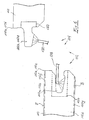
- panel 110 differs from the panel 10 according to Fig. 3 and 4 on the one hand, that the coupling means 112 formed on the side edges 110a-110d are not formed so that two adjacent panels can be connected to each other by angling the spring panel into the groove panel, but the panels 110 are connected by a substantially planar telescoping parallel to the panel plane E. become.
- the locking means 114 are in this case formed by a projection 114a at the free end of the groove 112a, 112c limiting lower lip 116 and by a recess 114b in the region of the transition of the spring 112b, 112d in the panel 110.
- both the groove 112a, 112c and the spring 112b, 112d provided with a roughening 118, on the one hand to an upper boundary surface 116a of the lower lip 116 and the other to a lower boundary surface 122 of the spring 112b, 112d.
- the roughenings 118 are formed in the present case of particles 118a, which by means of a spray tool 128 or 130 (see Fig. 6 ) on the surfaces 116a and 126th can be applied, preferably using a primer that holds the particles 118a after it has dried on the surfaces 116a, 126.
- a solvent can also be applied to the surfaces 116a and 126, which at least solves a wood material used for forming the panels 110, for example solid wood, MDF or the like, so that individual wood fibers are at least partially made loosen the material composite and protrude from the surface after drying of the treatment agent.
- a wood material used for forming the panels 110 for example solid wood, MDF or the like
- Fig. 5 118a denotes the wood fibers protruding from the surfaces 116a and 126a.
- the panels 10, 110 can be made of any material, such as a wood material, such as solid wood boards, MDF boards, chipboard or the like, or even of compact laminate, plastic and the like suitable panel materials.
- a core 10e, 110e which is formed for example as MDF board (medium-density fiberboard), said core 10e, 110e at its footprint E a decorative layer 10f, 110f and its the loading side E opposite, lying on the bottom bottom B with a leveling layer 10g, 110g is glued.
- the decorative layer 10f, 110f may, for example, comprise one or more layers of printed paper impregnated with synthetic resin.
- the compensating layer 10g, 100g may also be formed by such a laminate layer comprising a plurality of paper layers.
- the groove 112a, 112c and the spring 112b, 112d need not necessarily be formed directly from the material of the core 110e. Rather, it is, as in Fig. 6 indicated by dashed lines, also possible to inject into a prepared in the side surface 110a to 110d recess 150 a suitable material, such as plastic, a wood extrudate or the like, and cure there and the groove 112a, 112c and the spring 112b, 112d thereafter to be trained by machining.
- a suitable material such as plastic, a wood extrudate or the like
Applications Claiming Priority (2)
| Application Number | Priority Date | Filing Date | Title |
|---|---|---|---|
| DE102004054368A DE102004054368A1 (de) | 2004-11-10 | 2004-11-10 | Verkleidungspaneel |
| EP05802289A EP1809833B1 (de) | 2004-11-10 | 2005-11-09 | Verkleidungspaneel |
Related Parent Applications (1)
| Application Number | Title | Priority Date | Filing Date |
|---|---|---|---|
| EP05802289A Division EP1809833B1 (de) | 2004-11-10 | 2005-11-09 | Verkleidungspaneel |
Publications (1)
| Publication Number | Publication Date |
|---|---|
| EP2085534A1 true EP2085534A1 (de) | 2009-08-05 |
Family
ID=35515658
Family Applications (2)
| Application Number | Title | Priority Date | Filing Date |
|---|---|---|---|
| EP05802289A Active EP1809833B1 (de) | 2004-11-10 | 2005-11-09 | Verkleidungspaneel |
| EP09160400A Withdrawn EP2085534A1 (de) | 2004-11-10 | 2005-11-09 | Verkleidungspaneel |
Family Applications Before (1)
| Application Number | Title | Priority Date | Filing Date |
|---|---|---|---|
| EP05802289A Active EP1809833B1 (de) | 2004-11-10 | 2005-11-09 | Verkleidungspaneel |
Country Status (18)
| Country | Link |
|---|---|
| US (1) | US8001741B2 (xx) |
| EP (2) | EP1809833B1 (xx) |
| JP (1) | JP5122971B2 (xx) |
| CN (2) | CN101591965A (xx) |
| AT (1) | ATE440189T1 (xx) |
| AU (1) | AU2005303947B2 (xx) |
| CA (1) | CA2586186C (xx) |
| DE (2) | DE102004054368A1 (xx) |
| DK (1) | DK1809833T3 (xx) |
| ES (1) | ES2329267T3 (xx) |
| HR (1) | HRP20090476T1 (xx) |
| MX (1) | MX2007005540A (xx) |
| PL (1) | PL1809833T3 (xx) |
| PT (1) | PT1809833E (xx) |
| RU (1) | RU2358073C2 (xx) |
| SI (1) | SI1809833T1 (xx) |
| UA (1) | UA88490C2 (xx) |
| WO (1) | WO2006050928A1 (xx) |
Families Citing this family (69)
| Publication number | Priority date | Publication date | Assignee | Title |
|---|---|---|---|---|
| US7086205B2 (en) | 1993-05-10 | 2006-08-08 | Valinge Aluminium Ab | System for joining building panels |
| SE517183C2 (sv) | 2000-01-24 | 2002-04-23 | Valinge Aluminium Ab | Låssystem för mekanisk hopfogning av golvskivor, golvskiva försedd med låssystemet och metod för framställning av sådana golvskivor |
| SE518184C2 (sv) | 2000-03-31 | 2002-09-03 | Perstorp Flooring Ab | Golvbeläggningsmaterial innefattande skivformiga golvelement vilka sammanfogas med hjälp av sammankopplingsorgan |
| US20040211144A1 (en) * | 2001-06-27 | 2004-10-28 | Stanchfield Oliver O. | Flooring panel or wall panel and use thereof |
| US8028486B2 (en) | 2001-07-27 | 2011-10-04 | Valinge Innovation Ab | Floor panel with sealing means |
| SE525661C2 (sv) | 2002-03-20 | 2005-03-29 | Vaelinge Innovation Ab | System för bildande av dekorativa fogpartier och golvskivor därför |
| EP2287419A3 (en) | 2002-04-03 | 2011-11-30 | Välinge Innovation AB | Floorboard |
| SE525657C2 (sv) | 2002-04-08 | 2005-03-29 | Vaelinge Innovation Ab | Golvskivor för flytande golv framställda av åtminstone två olika materialskikt samt halvfabrikat för tillverkning av golvskivor |
| US8850769B2 (en) | 2002-04-15 | 2014-10-07 | Valinge Innovation Ab | Floorboards for floating floors |
| US8375673B2 (en) * | 2002-08-26 | 2013-02-19 | John M. Evjen | Method and apparatus for interconnecting paneling |
| US7845140B2 (en) | 2003-03-06 | 2010-12-07 | Valinge Innovation Ab | Flooring and method for installation and manufacturing thereof |
| US7677001B2 (en) | 2003-03-06 | 2010-03-16 | Valinge Innovation Ab | Flooring systems and methods for installation |
| US7886497B2 (en) | 2003-12-02 | 2011-02-15 | Valinge Innovation Ab | Floorboard, system and method for forming a flooring, and a flooring formed thereof |
| US20050166516A1 (en) | 2004-01-13 | 2005-08-04 | Valinge Aluminium Ab | Floor covering and locking systems |
| SE527570C2 (sv) | 2004-10-05 | 2006-04-11 | Vaelinge Innovation Ab | Anordning och metod för ytbehandling av skivformat ämne samt golvskiva |
| US7841144B2 (en) | 2005-03-30 | 2010-11-30 | Valinge Innovation Ab | Mechanical locking system for panels and method of installing same |
| US8215078B2 (en) | 2005-02-15 | 2012-07-10 | Välinge Innovation Belgium BVBA | Building panel with compressed edges and method of making same |
| US8061104B2 (en) | 2005-05-20 | 2011-11-22 | Valinge Innovation Ab | Mechanical locking system for floor panels |
| SE533410C2 (sv) | 2006-07-11 | 2010-09-14 | Vaelinge Innovation Ab | Golvpaneler med mekaniska låssystem med en flexibel och förskjutbar tunga samt tunga därför |
| US7861482B2 (en) | 2006-07-14 | 2011-01-04 | Valinge Innovation Ab | Locking system comprising a combination lock for panels |
| DE102006051840A1 (de) * | 2006-08-09 | 2008-02-14 | Agepan-Tarkett Laminatepark Eiweiler Gmbh & Co. Kg | Befestigungssystem für tafelförmige Paneele |
| DE102006052081A1 (de) * | 2006-11-04 | 2008-05-08 | Agepan-Tarkett Laminatepark Eiweiler Gmbh & Co. Kg | Befestigungssystem für tafelförmige Paneele |
| US8689512B2 (en) | 2006-11-15 | 2014-04-08 | Valinge Innovation Ab | Mechanical locking of floor panels with vertical folding |
| CA2669105C (en) * | 2006-11-15 | 2016-10-25 | Vaelinge Innovation Ab | Mechanical locking of floor panels with vertical folding |
| US11725394B2 (en) | 2006-11-15 | 2023-08-15 | Välinge Innovation AB | Mechanical locking of floor panels with vertical folding |
| SE532607C2 (sv) * | 2006-11-15 | 2010-03-02 | Vaelinge Innovation Ab | Mekanisk låsning av golvpaneler med vertikal vikning |
| SE531111C2 (sv) | 2006-12-08 | 2008-12-23 | Vaelinge Innovation Ab | Mekanisk låsning av golvpaneler |
| EP2235286B1 (en) | 2007-11-07 | 2019-01-02 | Välinge Innovation AB | Mechanical locking of floor panels with vertical snap folding and an installation method to connect such panels |
| US8353140B2 (en) * | 2007-11-07 | 2013-01-15 | Valinge Innovation Ab | Mechanical locking of floor panels with vertical snap folding |
| US8505257B2 (en) | 2008-01-31 | 2013-08-13 | Valinge Innovation Ab | Mechanical locking of floor panels |
| CA2712099C (en) | 2008-01-31 | 2016-07-05 | Darko Pervan | Mechanical locking of floor panels, methods to install and uninstall panels, a method and an equipment to produce the locking system, a method to connect a displaceable tongue to a panel and a tongue blank |
| WO2009139687A1 (en) | 2008-05-15 | 2009-11-19 | Välinge Innovation AB | Floor panels with a mechanical locking system activated by a magnetic field and a method to install the panels |
| DE202008010555U1 (de) * | 2008-08-08 | 2009-12-17 | Akzenta Paneele + Profile Gmbh | Kunststoffpaneel mit Hakenprofil |
| US20100068451A1 (en) * | 2008-09-17 | 2010-03-18 | David Richard Graf | Building panel with wood facing layer and composite substrate backing layer |
| DK2391783T3 (en) | 2009-01-30 | 2018-03-12 | Vaelinge Innovation Ab | MECHANICAL LOCKING OF FLOOR PANELS AND A SINGLE BODY |
| US8544230B2 (en) | 2010-01-12 | 2013-10-01 | Valinge Innovation Ab | Mechanical locking system for floor panels |
| EP2531667B1 (en) | 2010-02-04 | 2020-08-26 | Välinge Innovation AB | Mechanical locking system for floor panels and corresponding tongue |
| US8234830B2 (en) | 2010-02-04 | 2012-08-07 | Välinge Innovations AB | Mechanical locking system for floor panels |
| CN102844506B (zh) | 2010-04-15 | 2015-08-12 | 巴尔特利奥-斯巴诺吕克斯股份公司 | 地板组件 |
| US20120024347A1 (en) * | 2010-07-27 | 2012-02-02 | Tzy-Ying Lin | Solar package structure and method for fabricating the same |
| UA109938C2 (uk) | 2011-05-06 | 2015-10-26 | Механічна фіксуюча система для будівельних панелей | |
| UA114715C2 (uk) | 2011-07-05 | 2017-07-25 | Сералок Інновейшн Аб | Механічна фіксація панелей настилу підлоги до язичка з нанесеним шаром клею |
| US9725912B2 (en) | 2011-07-11 | 2017-08-08 | Ceraloc Innovation Ab | Mechanical locking system for floor panels |
| US8650826B2 (en) | 2011-07-19 | 2014-02-18 | Valinge Flooring Technology Ab | Mechanical locking system for floor panels |
| DE102012102339A1 (de) * | 2011-07-29 | 2013-01-31 | Hamberger Industriewerke Gmbh | Verbindung für elastische oder plattenförmige Bauelemente, Profilschieber und Fußbodenbelag |
| US8769905B2 (en) | 2011-08-15 | 2014-07-08 | Valinge Flooring Technology Ab | Mechanical locking system for floor panels |
| US8763340B2 (en) | 2011-08-15 | 2014-07-01 | Valinge Flooring Technology Ab | Mechanical locking system for floor panels |
| US8857126B2 (en) | 2011-08-15 | 2014-10-14 | Valinge Flooring Technology Ab | Mechanical locking system for floor panels |
| CN102373785A (zh) * | 2011-10-20 | 2012-03-14 | 宣建民 | 一种地板锁扣 |
| US9216541B2 (en) | 2012-04-04 | 2015-12-22 | Valinge Innovation Ab | Method for producing a mechanical locking system for building panels |
| US8596013B2 (en) | 2012-04-04 | 2013-12-03 | Valinge Innovation Ab | Building panel with a mechanical locking system |
| US20140318895A1 (en) * | 2013-04-29 | 2014-10-30 | John Birk | Adjustable length scaffolding and method therefor |
| US20130313046A1 (en) * | 2012-05-24 | 2013-11-28 | John Birk | Adjustable length scaffolding and method therefor |
| WO2014033628A1 (en) * | 2012-08-27 | 2014-03-06 | Pergo (Europe) Ab | Panel |
| EP3613920B1 (en) | 2012-11-22 | 2024-01-31 | Ceraloc Innovation AB | Mechanical locking system for floor panels |
| MX367290B (es) | 2013-06-27 | 2019-08-13 | Vaelinge Innovation Ab | Panel de construccion con un sistema de bloqueo mecanico. |
| CN103758322A (zh) * | 2013-06-30 | 2014-04-30 | 江西南丰振宇实业集团有限公司 | 一种新型锁扣地板 |
| US9260870B2 (en) | 2014-03-24 | 2016-02-16 | Ivc N.V. | Set of mutually lockable panels |
| CN106103862B (zh) | 2014-03-24 | 2020-01-10 | 地板工业有限公司 | 一组能够相互锁定的面板 |
| US10246883B2 (en) | 2014-05-14 | 2019-04-02 | Valinge Innovation Ab | Building panel with a mechanical locking system |
| BR112016025214B1 (pt) | 2014-05-14 | 2022-06-07 | Vãlinge Innovation Ab | Conjunto de painéis de construção com um sistema de travamento mecânico |
| RU2584985C2 (ru) * | 2014-07-15 | 2016-05-27 | Александр Григорьевич Леонтьев | Стеновая ламельная панель |
| EP3224427B1 (en) | 2014-11-27 | 2019-09-11 | Välinge Innovation AB | Set of essentially idencial floor panels with mechanical locking system |
| JP6077692B1 (ja) | 2016-03-04 | 2017-02-08 | 伸興化成株式会社 | リサイクル可能な合成樹脂タイル及びその製造方法 |
| DE102016118380A1 (de) * | 2016-09-28 | 2018-03-29 | Guido Schulte | Bodenbelag sowie Verfahren zum Verlegen des Bodenbelages |
| AU2017392352A1 (en) * | 2017-01-11 | 2019-08-29 | Concept Modular Limited | Improvements in modular construction systems |
| EP3645806A1 (en) | 2017-06-27 | 2020-05-06 | Flooring Industries Limited, SARL | Wall or ceiling panel and wall or ceiling assembly |
| US10927542B2 (en) * | 2017-09-20 | 2021-02-23 | Louisiana-Pacific Corporation | Integrated joint sealing system |
| KR20210110687A (ko) | 2019-01-10 | 2021-09-08 | 뵈린게 이노베이션 에이비이 | 수직으로 잠금해제될 수 있는 패널들의 세트, 이의 방법 및 디바이스 |
Citations (7)
| Publication number | Priority date | Publication date | Assignee | Title |
|---|---|---|---|---|
| WO1996023942A1 (en) * | 1995-01-30 | 1996-08-08 | Ab Golvabia | Jointing system |
| WO1997047834A1 (en) * | 1996-06-11 | 1997-12-18 | Unilin Beheer B.V. | Floor covering, consisting of hard floor panels and method for manufacturing such floor panels |
| WO1998022677A1 (en) * | 1996-11-18 | 1998-05-28 | Ab Golvabia | An arrangement for jointing together adjacent pieces of floor covering material |
| WO1998058142A1 (de) * | 1997-06-18 | 1998-12-23 | M. Kaindl | Anordnung mit bauteilen oder bauteile |
| US20010024707A1 (en) * | 1996-11-08 | 2001-09-27 | Kjell Andersson | Flooring |
| WO2003074814A1 (de) * | 2002-03-07 | 2003-09-12 | Fritz Egger Gmbh & Co. | Paneele mit auf reibung basierender fixierung |
| WO2004083557A1 (en) * | 2003-03-18 | 2004-09-30 | Pergo (Europe) Ab | Panel joint |
Family Cites Families (24)
| Publication number | Priority date | Publication date | Assignee | Title |
|---|---|---|---|---|
| FR1483017A (fr) * | 1966-04-22 | 1967-06-02 | Perfectionnements aux joints d'assemblage, pour éléments de construction et autres | |
| DK117103B (da) * | 1967-09-20 | 1970-03-16 | H Pedersen | Gulvelement af støbt eller presset materiale. |
| JPS51144013A (en) * | 1975-06-04 | 1976-12-10 | Kumagai Gumi Co Ltd | Beam body connected portion with closed shape section |
| GB1559636A (en) * | 1976-07-05 | 1980-01-23 | Baupres Ag | Building block |
| US6421970B1 (en) * | 1995-03-07 | 2002-07-23 | Perstorp Flooring Ab | Flooring panel or wall panel and use thereof |
| US5618602A (en) * | 1995-03-22 | 1997-04-08 | Wilsonart Int Inc | Articles with tongue and groove joint and method of making such a joint |
| JPH09317132A (ja) * | 1996-05-28 | 1997-12-09 | Niyuucom:Kk | 仮設フロア |
| SE507737C2 (sv) * | 1996-11-08 | 1998-07-06 | Golvabia Ab | Anordning för sammanfogning av golvbeläggningsmaterial |
| SE513151C2 (sv) * | 1998-02-04 | 2000-07-17 | Perstorp Flooring Ab | Styrklack vid fog innefattande not och fjäder |
| DE19851200C1 (de) * | 1998-11-06 | 2000-03-30 | Kronotex Gmbh Holz Und Kunstha | Fußbodenpaneele |
| TW420621B (en) * | 1999-01-15 | 2001-02-01 | Interlego Ag | A toy building set |
| ATE277246T1 (de) * | 1999-06-30 | 2004-10-15 | Akzenta Paneele & Profile Gmbh | Paneel sowie befestigungssystem für paneele |
| DE10034409A1 (de) * | 2000-07-14 | 2002-01-24 | Kronotec Ag | Einrichtung zum Verbinden von Bauplatten, insbesondere Bodenpaneele |
| EP1277896A1 (en) * | 2001-07-16 | 2003-01-22 | Ulf Palmberg | Floorboards |
| DE10141791A1 (de) * | 2001-08-25 | 2003-03-06 | Kronotec Ag | Paneel, insbesondere Bodenpaneel |
| DE10159284B4 (de) * | 2001-12-04 | 2005-04-21 | Kronotec Ag | Gebäudeplatte, insbesondere Bodenpaneel |
| SE525661C2 (sv) * | 2002-03-20 | 2005-03-29 | Vaelinge Innovation Ab | System för bildande av dekorativa fogpartier och golvskivor därför |
| AT413228B (de) * | 2002-08-19 | 2005-12-15 | Kaindl M | Verkleidungsplatte |
| DE20219023U1 (de) * | 2002-12-06 | 2003-02-20 | Hdm Holz Dammers Gmbh | Paneel, insbesondere Fußbodenpaneel |
| AT501440A1 (de) * | 2003-03-07 | 2006-09-15 | Kaindl Flooring Gmbh | Verkleidungsplatte |
| DE10329686B4 (de) * | 2003-07-02 | 2008-02-28 | Akzenta Paneele + Profile Gmbh | Paneel mit Verriegelungssystem |
| CN2641200Y (zh) * | 2003-08-19 | 2004-09-15 | 石学军 | 一种拼装地板 |
| US8061104B2 (en) * | 2005-05-20 | 2011-11-22 | Valinge Innovation Ab | Mechanical locking system for floor panels |
| DE102006051840A1 (de) * | 2006-08-09 | 2008-02-14 | Agepan-Tarkett Laminatepark Eiweiler Gmbh & Co. Kg | Befestigungssystem für tafelförmige Paneele |
-
2004
- 2004-11-10 DE DE102004054368A patent/DE102004054368A1/de not_active Withdrawn
-
2005
- 2005-11-09 CA CA2586186A patent/CA2586186C/en active Active
- 2005-11-09 WO PCT/EP2005/011988 patent/WO2006050928A1/de active Application Filing
- 2005-11-09 CN CNA2009101453205A patent/CN101591965A/zh active Pending
- 2005-11-09 AU AU2005303947A patent/AU2005303947B2/en not_active Ceased
- 2005-11-09 PT PT05802289T patent/PT1809833E/pt unknown
- 2005-11-09 EP EP05802289A patent/EP1809833B1/de active Active
- 2005-11-09 MX MX2007005540A patent/MX2007005540A/es active IP Right Grant
- 2005-11-09 DK DK05802289T patent/DK1809833T3/da active
- 2005-11-09 ES ES05802289T patent/ES2329267T3/es active Active
- 2005-11-09 DE DE502005007964T patent/DE502005007964D1/de active Active
- 2005-11-09 EP EP09160400A patent/EP2085534A1/de not_active Withdrawn
- 2005-11-09 JP JP2007540567A patent/JP5122971B2/ja not_active Expired - Fee Related
- 2005-11-09 RU RU2007121686/03A patent/RU2358073C2/ru active
- 2005-11-09 US US11/718,822 patent/US8001741B2/en active Active
- 2005-11-09 SI SI200530846T patent/SI1809833T1/sl unknown
- 2005-11-09 PL PL05802289T patent/PL1809833T3/pl unknown
- 2005-11-09 CN CN200580038493A patent/CN100575638C/zh active Active
- 2005-11-09 AT AT05802289T patent/ATE440189T1/de active
- 2005-11-09 UA UAA200706410A patent/UA88490C2/ru unknown
-
2009
- 2009-09-08 HR HR20090476T patent/HRP20090476T1/xx unknown
Patent Citations (11)
| Publication number | Priority date | Publication date | Assignee | Title |
|---|---|---|---|---|
| WO1996023942A1 (en) * | 1995-01-30 | 1996-08-08 | Ab Golvabia | Jointing system |
| WO1997047834A1 (en) * | 1996-06-11 | 1997-12-18 | Unilin Beheer B.V. | Floor covering, consisting of hard floor panels and method for manufacturing such floor panels |
| EP0843763A1 (en) | 1996-06-11 | 1998-05-27 | Unilin Beheer B.V. | Floor covering, consisting of hard floor panels and method for manufacturing such floor panels |
| EP1024234A2 (en) | 1996-06-11 | 2000-08-02 | Unilin Beheer B.V. | Floor covering, consisting of hard floor panels and method for manufacturing such floor panels |
| EP1026341A2 (en) | 1996-06-11 | 2000-08-09 | Unilin Beheer B.V. | Floor covering, consisting of hard floor panels and method for manufacturing such floor panels |
| US20010024707A1 (en) * | 1996-11-08 | 2001-09-27 | Kjell Andersson | Flooring |
| WO1998022677A1 (en) * | 1996-11-18 | 1998-05-28 | Ab Golvabia | An arrangement for jointing together adjacent pieces of floor covering material |
| WO1998058142A1 (de) * | 1997-06-18 | 1998-12-23 | M. Kaindl | Anordnung mit bauteilen oder bauteile |
| EP1036244B1 (de) | 1997-06-18 | 2003-08-06 | M. Kaindl | Platten- oder leistenförmige Bauteile |
| WO2003074814A1 (de) * | 2002-03-07 | 2003-09-12 | Fritz Egger Gmbh & Co. | Paneele mit auf reibung basierender fixierung |
| WO2004083557A1 (en) * | 2003-03-18 | 2004-09-30 | Pergo (Europe) Ab | Panel joint |
Also Published As
| Publication number | Publication date |
|---|---|
| CN101591965A (zh) | 2009-12-02 |
| AU2005303947A1 (en) | 2006-05-18 |
| JP5122971B2 (ja) | 2013-01-16 |
| DK1809833T3 (da) | 2009-11-23 |
| CN100575638C (zh) | 2009-12-30 |
| RU2007121686A (ru) | 2008-12-20 |
| PT1809833E (pt) | 2009-09-30 |
| WO2006050928A1 (de) | 2006-05-18 |
| RU2358073C2 (ru) | 2009-06-10 |
| EP1809833A1 (de) | 2007-07-25 |
| CN101218402A (zh) | 2008-07-09 |
| ATE440189T1 (de) | 2009-09-15 |
| AU2005303947B2 (en) | 2011-02-24 |
| CA2586186A1 (en) | 2006-05-18 |
| DE102004054368A1 (de) | 2006-05-11 |
| CA2586186C (en) | 2014-02-04 |
| MX2007005540A (es) | 2007-07-25 |
| JP2008520853A (ja) | 2008-06-19 |
| US8001741B2 (en) | 2011-08-23 |
| US20080000185A1 (en) | 2008-01-03 |
| ES2329267T3 (es) | 2009-11-24 |
| HRP20090476T1 (en) | 2009-10-31 |
| SI1809833T1 (sl) | 2010-01-29 |
| UA88490C2 (xx) | 2009-10-26 |
| EP1809833B1 (de) | 2009-08-19 |
| PL1809833T3 (pl) | 2010-01-29 |
| DE502005007964D1 (de) | 2009-10-01 |
Similar Documents
| Publication | Publication Date | Title |
|---|---|---|
| EP1809833B1 (de) | Verkleidungspaneel | |
| EP2478168B1 (de) | Belag aus mechanisch miteinander verbindbaren elementen und ein verfahren zur herstellung von elementen | |
| EP2318614B1 (de) | Kunststoffpaneel mit hakenprofil | |
| DE69916666T2 (de) | Rechteckige Bodenplatte | |
| EP1885970B1 (de) | Verfahren zum verlegen und mechanischen verbinden von paneelen | |
| EP1985464B1 (de) | Bauplatte, insbesondere Fußbodenpaneel, und Verfahren zu deren Herstellung | |
| EP2250330B1 (de) | Verfahren zum verlegen von fussbodenpaneelen | |
| EP2795017B1 (de) | Paneel eines fussbodenbelags mit einer entlang einer seitenkante geneigten verriegelungsfläche | |
| DE69926608T2 (de) | Fussbodensystem umfassend Fussbodenplatten mit Führungsmitteln | |
| EP1400641A2 (de) | Paneele mit Verbindungsklammer | |
| WO2002001018A1 (de) | Fussbodenplatte | |
| EP1917407A1 (de) | Lösbar aneinander zu befestigende, flächige bauteile, insbesondere bodenbelagsteile, sowie bauteil | |
| EP2054566B1 (de) | Befestigungssystem für tafelförmige paneele | |
| DE102008021970B4 (de) | Paneel mit vereinfachtem Rastelement | |
| EP2955295B1 (de) | Verfahren zum Herstellen eines Paneels | |
| DE102009040114A1 (de) | Paneel zur Bildung eines Belags und Verfahren zur Herstellung eines solchen Paneels | |
| DE202010017748U1 (de) | Belag aus mechanisch miteinander verbindbaren Elementen | |
| DE202019101603U1 (de) | Lösbare Verbindung von Baupaneelen zur Montage eines Mosaik-Flächenbelags | |
| WO2016180980A1 (de) | Paneel und verfahren zum verlegen von paneelen | |
| DE10133101B4 (de) | Fußbodenbelagselement mit Paneelen | |
| EP1183138A1 (de) | Parkettlamelle, deren verwendung zur herstellung eines paneels oder parkettelementes, sowie hieraus hergestelltes parkettelement und verfahren zur herstellung einer parkettlamelle | |
| EP4081686B1 (de) | Wand-, decken- oder dachelementverbindung | |
| EP3907346B1 (de) | Mehrprofilpaneel | |
| EP2403712A1 (de) | Leichtbauplatte sowie verfahren und vorrichtung zu deren herstellung | |
| DE202009011997U1 (de) | Paneel zur Bildung eines Belags |
Legal Events
| Date | Code | Title | Description |
|---|---|---|---|
| PUAI | Public reference made under article 153(3) epc to a published international application that has entered the european phase |
Free format text: ORIGINAL CODE: 0009012 |
|
| 17P | Request for examination filed |
Effective date: 20090515 |
|
| AC | Divisional application: reference to earlier application |
Ref document number: 1809833 Country of ref document: EP Kind code of ref document: P |
|
| AK | Designated contracting states |
Kind code of ref document: A1 Designated state(s): AT BE BG CH CY CZ DE DK EE ES FI FR GB GR HU IE IS IT LI LT LU LV MC NL PL PT RO SE SI SK TR |
|
| AX | Request for extension of the european patent |
Extension state: HR |
|
| RIN1 | Information on inventor provided before grant (corrected) |
Inventor name: DUERNBERGER, GERHARD |
|
| 17Q | First examination report despatched |
Effective date: 20090930 |
|
| STAA | Information on the status of an ep patent application or granted ep patent |
Free format text: STATUS: THE APPLICATION IS DEEMED TO BE WITHDRAWN |
|
| 18D | Application deemed to be withdrawn |
Effective date: 20100211 |