EP2080624A1 - Verfahren zum Herstellen eines Bauteils mit einer bedruckten Echtholzoberfläche vorbestimmen Aussehens - Google Patents
Verfahren zum Herstellen eines Bauteils mit einer bedruckten Echtholzoberfläche vorbestimmen Aussehens Download PDFInfo
- Publication number
- EP2080624A1 EP2080624A1 EP09001678A EP09001678A EP2080624A1 EP 2080624 A1 EP2080624 A1 EP 2080624A1 EP 09001678 A EP09001678 A EP 09001678A EP 09001678 A EP09001678 A EP 09001678A EP 2080624 A1 EP2080624 A1 EP 2080624A1
- Authority
- EP
- European Patent Office
- Prior art keywords
- printed
- wood
- wood surface
- real wood
- component
- Prior art date
- Legal status (The legal status is an assumption and is not a legal conclusion. Google has not performed a legal analysis and makes no representation as to the accuracy of the status listed.)
- Withdrawn
Links
Images


Classifications
-
- B—PERFORMING OPERATIONS; TRANSPORTING
- B44—DECORATIVE ARTS
- B44C—PRODUCING DECORATIVE EFFECTS; MOSAICS; TARSIA WORK; PAPERHANGING
- B44C5/00—Processes for producing special ornamental bodies
- B44C5/04—Ornamental plaques, e.g. decorative panels, decorative veneers
- B44C5/0446—Ornamental plaques, e.g. decorative panels, decorative veneers bearing graphical information
-
- B—PERFORMING OPERATIONS; TRANSPORTING
- B27—WORKING OR PRESERVING WOOD OR SIMILAR MATERIAL; NAILING OR STAPLING MACHINES IN GENERAL
- B27N—MANUFACTURE BY DRY PROCESSES OF ARTICLES, WITH OR WITHOUT ORGANIC BINDING AGENTS, MADE FROM PARTICLES OR FIBRES CONSISTING OF WOOD OR OTHER LIGNOCELLULOSIC OR LIKE ORGANIC MATERIAL
- B27N7/00—After-treatment, e.g. reducing swelling or shrinkage, surfacing; Protecting the edges of boards against access of humidity
- B27N7/005—Coating boards, e.g. with a finishing or decorating layer
-
- B—PERFORMING OPERATIONS; TRANSPORTING
- B41—PRINTING; LINING MACHINES; TYPEWRITERS; STAMPS
- B41J—TYPEWRITERS; SELECTIVE PRINTING MECHANISMS, i.e. MECHANISMS PRINTING OTHERWISE THAN FROM A FORME; CORRECTION OF TYPOGRAPHICAL ERRORS
- B41J3/00—Typewriters or selective printing or marking mechanisms characterised by the purpose for which they are constructed
- B41J3/407—Typewriters or selective printing or marking mechanisms characterised by the purpose for which they are constructed for marking on special material
- B41J3/4073—Printing on three-dimensional objects not being in sheet or web form, e.g. spherical or cubic objects
-
- B—PERFORMING OPERATIONS; TRANSPORTING
- B44—DECORATIVE ARTS
- B44F—SPECIAL DESIGNS OR PICTURES
- B44F9/00—Designs imitating natural patterns
- B44F9/02—Designs imitating natural patterns wood grain effects
-
- B—PERFORMING OPERATIONS; TRANSPORTING
- B27—WORKING OR PRESERVING WOOD OR SIMILAR MATERIAL; NAILING OR STAPLING MACHINES IN GENERAL
- B27N—MANUFACTURE BY DRY PROCESSES OF ARTICLES, WITH OR WITHOUT ORGANIC BINDING AGENTS, MADE FROM PARTICLES OR FIBRES CONSISTING OF WOOD OR OTHER LIGNOCELLULOSIC OR LIKE ORGANIC MATERIAL
- B27N3/00—Manufacture of substantially flat articles, e.g. boards, from particles or fibres
- B27N3/08—Moulding or pressing
- B27N3/18—Auxiliary operations, e.g. preheating, humidifying, cutting-off
-
- B—PERFORMING OPERATIONS; TRANSPORTING
- B29—WORKING OF PLASTICS; WORKING OF SUBSTANCES IN A PLASTIC STATE IN GENERAL
- B29C—SHAPING OR JOINING OF PLASTICS; SHAPING OF MATERIAL IN A PLASTIC STATE, NOT OTHERWISE PROVIDED FOR; AFTER-TREATMENT OF THE SHAPED PRODUCTS, e.g. REPAIRING
- B29C2793/00—Shaping techniques involving a cutting or machining operation
- B29C2793/0027—Cutting off
-
- B—PERFORMING OPERATIONS; TRANSPORTING
- B41—PRINTING; LINING MACHINES; TYPEWRITERS; STAMPS
- B41M—PRINTING, DUPLICATING, MARKING, OR COPYING PROCESSES; COLOUR PRINTING
- B41M5/00—Duplicating or marking methods; Sheet materials for use therein
- B41M5/0011—Pre-treatment or treatment during printing of the recording material, e.g. heating, irradiating
-
- B—PERFORMING OPERATIONS; TRANSPORTING
- B41—PRINTING; LINING MACHINES; TYPEWRITERS; STAMPS
- B41M—PRINTING, DUPLICATING, MARKING, OR COPYING PROCESSES; COLOUR PRINTING
- B41M5/00—Duplicating or marking methods; Sheet materials for use therein
- B41M5/0041—Digital printing on surfaces other than ordinary paper
- B41M5/0047—Digital printing on surfaces other than ordinary paper by ink-jet printing
-
- B—PERFORMING OPERATIONS; TRANSPORTING
- B41—PRINTING; LINING MACHINES; TYPEWRITERS; STAMPS
- B41M—PRINTING, DUPLICATING, MARKING, OR COPYING PROCESSES; COLOUR PRINTING
- B41M5/00—Duplicating or marking methods; Sheet materials for use therein
- B41M5/0041—Digital printing on surfaces other than ordinary paper
- B41M5/0076—Digital printing on surfaces other than ordinary paper on wooden surfaces, leather, linoleum, skin, or flowers
Definitions
- the invention relates to a method for producing a component with a printed real wood surface of predetermined appearance.
- a method for producing flat components with a predetermined appearance of their surface in which the surface components are printed by means of a method that can be programmed with regard to the resulting appearance in order to form a predetermined pattern.
- surfaces made of wood may be printed with a pattern whose grain corresponds to a predetermined wood species and whose color corresponds to a predetermined hue.
- the method can also be used to print on three-dimensional surfaces.
- a multi-color printing device which contains a print head containing the ink, such as ink jet print head, and a guide device for the object to be printed, can be printed with the arbitrarily high objects by the distance between the printing unit and the receiving surface for the object to be printed adjustable is.
- a problem which arises in components to be produced with a surface of predetermined appearance is that, for example, plate-shaped components provided with a wood grain do not have the appearance of real wood panels, since their side surfaces, like the surface, are indeed printed with a wood grain However, the wood grains of the top and the visible side surfaces do not match, leaving the viewer From the outset sees that it is not a solid wood panel, but a veneered panel.
- the invention has for its object to provide a method for producing a component with a printed real wood surface, with the cost components with high-quality-looking surfaces can be produced.
- Fig. 1 There is a base body 2 on a transport plate 4, which is movable in a plane perpendicular to the plane, ie in the x and y direction, by means not shown transport means.
- a transport plate 4 Above the transport plate 4 is an ink jet printing device 6, which contains an ink jet head 8, which is pivotable on an arm 10 about an axis B perpendicular to the drawing plane in the example shown.
- the arm 10 is pivotally supported on a bracket 12 about a vertical axis A, which console 12 in turn is telescopically slidably received relative to a cylinder 14 in the Z direction. Drive means for the pivoting movements and the telescopic displacement are not shown.
- the position of the main body 2 is detected by means of a sensor device 16.
- an electronic control unit 18 which includes a microprocessor 20 with associated program and data storage 22, 24. Inputs 26 of the control unit 18 are connected to the sensor device 16; Exits 28 are connected to the various drive means and the ink jet printhead.
- the described device it is possible with the described device to move the ink jet print head 8 relative to the base body 2 such that the ink jet print head 8, the entire surface of the base body 2 including the side surfaces while maintaining a predetermined distance between the ink jet print head 8 and the surface of the base body 2 and a predetermined angle between the ejected from the ink jet print head 8 ink jet and the surface of the base body 2 sweeps.
- projections, recesses or other irregularities of the main body 2 can be covered in this way.
- the base body 2 may be stationary and the ink jet printing head 8 may be moved and pivoted.
- the ink jet print head 8 can be stationary and the base body 2 can be pivoted and moved linearly.
- a pattern to be applied to the base body 2 is stored such that each surface point of the base body 2 is assigned a color pixel in the manner of the color and quantity.
- the screen resolution depends on the requirements and technical possibilities.
- the geometry of the base body can be stored in its entirety in the control unit 18, so that only one reference position of the base body 2 has to be detected by means of the sensor device 16.
- the sensor device itself can sensors on the print head 8, for example Ultrasonic sensors, be attached, which detect the distance between the ink jet print head 8 and the surface of the base body 2 and their relative orientation.
- An exemplary sensor device is in the aforementioned EP 0 931 649 A2 described.
- the in Fig. 2 left branch corresponds to the production of a component from a provided with a real wood surface body.
- the right branch corresponds to the production of a component from a base body provided with a plastic surface.
- a green body is cut from a pressboard whose dimensions correspond approximately to those of the component to be produced.
- the green body can be made of any suitable material, for example, from a low-weight honey-comb structure, which consists of plastic or fiber composite material. In the example shown, it is assumed that the green body has a plate-like shape.
- a real wood veneer is applied in a manner known per se at least on the upper side of the green body.
- the real wood veneer may consist of inexpensive wood, such as ash, birch, beech, elm or other inexpensive quality timbers.
- step 34 the side surfaces of the plate-shaped, provided with a veneer green body, which is for example one centimeter thick, provided with edge elements, which may also be wood veneers, but may also be formed by Kunststoffumleimer etc. Further, in step 34, the transition between the edge elements and the other surfaces of the body is machined clean mechanically, so that the dimensions of the now forming a body raw body after step 34 correspond to the manufactured finished component.
- step 36 the surface of the green body is provided with an embossing as needed, for example by calendering.
- step 38 the surface is ground with a roughness adapted to the subsequent steps.
- the ground surface is provided with a primer layer.
- the priming may be similar to that of Fig. 1 trained device, wherein the ink jet print head 8 is replaced by a spray head.
- the priming can also be done in other devices, for example by immersing the body in primer liquid.
- the step 42 is followed by a step 44, in which the inkjet-printed body is provided with a protective layer, which can be applied by spraying, rolling, dipping, etc.
- a raw plate is cut, which is provided in step 54 with a border, such as a lipping.
- the transition between the edge band and the plate surface is machined clean mechanically, so that the shape of the manufactured base body corresponds to that of a component to be produced.
- step 56 the base body is provided with an embossing if necessary.
- Step 56 is followed by a priming step 60, in which the surface of the base is primed such that the ink applied in the subsequent ink jet printing step 42 adheres properly to the surface.
- the protective step 44 is followed by the step 42 for finishing.
- Fig. 3 shows different, formed on a green body 70 edge elements.
- Fig. 3a shows a rim member 72 which is formed as a bar or strip of uniform thickness.
- the edge element according to Fig. 3b has triangular cross-section.
- the edge element 76 is rounded.
- the transition region between the edge element and the green body is in each case treated cleanly mechanically so that the base body produced has no imperfections in the transition to or to the edge elements.
- its edge can also be shaped without any separately applied edge element merely by mechanical processing.
- Fig. 4 illustrates in the figure parts a) and b) different surface textures of the respective base body 78th
- Fig. 4a are embossed into the surfaces line or slot-shaped incisions.
- Fig. 4b the surface is marked with punctiform depressions or holes.
- the structuring may vary depending on the intended use of the component to be produced and the desired surface appearance; Relief-like surface structures, as can be produced, for example, by rough grinding, are just as possible as fine calendering.
- the grinding step 38 also greatly affects the appearance of the subsequent ink jet printing. A rough cut leads to a bleeding of the color dots. With increasingly fine cut increasingly sharply drawn patterns can muster.
- the primer applied in steps 40 and 60 not only serves for good adhesion of the printed ink.
- the primer can also influence the absorption behavior of the surface which, in addition to the amount and dye content of the ink, affects whether the pattern applied by inkjet printing is fully opaque or merely translucent.
- Fig. 5 illustrates an aspect that is important when printing on edges of a plate or heavily curved surface areas.
- edges are preferably printed such that the ink jet 80 of the surface being printed does not reach the adjacent surface. This is achieved by the angle ⁇ between the ink jet and the surface being printed being slightly less than 90, so that the unprinted surface is shaded. Above the shaded area, in order to fully ensure that no ink settles there, a suction device, for example a vacuum nozzle, may be arranged.
- the ink jet printing head 8 With a predetermined distance and while maintaining a predetermined orientation, preferably an approximately right angle, the currently printed surface element along a rounded edge of a base body 78 moves relative to this, the ink jet printing is preferably such that the amount of ink reaching a surface unit regardless of Curvature of the surface of the body 78 is.
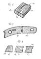
- Fig. 6 shows a perspective view of a producible by the process according to the invention component, for example, a part of a front side of a kitchen forming lid.
- the component 90 has an upper side 92 and two side surfaces 94 and 96.
- the wood grain patterns on top 92 and side surfaces 94 and 96 are formed to conform to a real wood board cut out of a tree, with the cut directions parallel to side surface 96 and perpendicular to side surface 94 and top surface 92, respectively lie.
- the woodgrain pattern of the side surface 96 thus corresponds to a frontal wood.
- the grains of the side surfaces 94 and 96 close to the grain of the top 92 steadily, ie the grain lines are merging in the edges into each other.
- step 42 By the method according to the invention can be represented by corresponding records alone in the ink jet printing step 42 a wide variety of woods with different nuances in an indistinguishable from real wood appearance. This is especially successful if step 42 ( Fig. 2 ) is performed on a natural wood veneered body.
- the wood veneer gives the printed body a real wood appearance, with a natural grain of the veneer is covered by the printed grain so that it no longer appears.
- embossing, grinding and priming of the base body is prepared so that the applied pattern of a real wood grain is indistinguishable.
- the protective layer applied in step 44 for example transparent two-component lacquer with the respective requirement of gloss, makes the component produced according to the invention hard-wearing and wear-resistant.
- the patterns may be taken directly from a master of the base in solid wood and used as datasets to control the inkjet printhead similar to printing a color original.
- patterns may be computationally generated according to respective templates, so that a variety of patterns that are not limited to woodgrain patterns can be generated.
- the data calculation takes place in such a way that the pattern contours (and colors) merge into one another according to the respective cuts at the edges (which can also be formed with radii of curvature).
- Data stores may store a sample of a variety of woods or other geometric or spatial patterns, each read out according to the desired size and used for printing.
- the color or coloration of the veneer may affect the appearance of the finished base.
- White bleached veneers lead to a clearer color embossing of the finished pattern.
- Tinted veneers result in less pronounced, more homogeneous dyeings of the finished pattern, if one does not work with a high degree of coverage.
- Fig. 7 shows an example of two vehicle interior deerboard components 98 and 100 printed according to the invention with woodgrain patterns.
- the woodgrain patterns in the area in which the components 98 and 100 adjoin one another are matched to one another in such a way that that they correspond or merge. In this way, the impression is created that the two components 98 and 100 are made of a single piece of natural wood, which increases the quality of the appearance.
- Fig. 8 shows how stored by appropriate data processing patterns can be adapted to the geometry of the component to be manufactured.
- Fig. 8b shows a basic pattern of a rectangular component 102.
- Fig. 8a shows the pattern corresponding to the component 102 on a component 104, which tapers in accordance with the figure upwards. The pattern lines are compressed according to the taper of the component.
- Fig. 8c shows a component 106, which is constricted in its central region.
- the pattern is constricted according to the constriction of the component. It is understood that the variations of the pattern present on the component 102 corresponding to the component 104 and 106 generally no longer correspond to a natural solid wood pattern; however, the effects produced by the compression of the patterns produce an aesthetically pleasing appearance of the components.
- the invention can be modified in many different ways. Various method steps can be combined with one another in a wide variety of ways, so that, with the exception of the inkjet printing method, only individual steps of the sequences according to FIG Fig. 2 must be present.
- left branch can, for example, if the starting body is a solid wood body made of simple wood, the veneer level, the boundary level and the embossing stage are missing.
- a veneer stage and a grinding stage can be provided in the right branch.
- the embossing steps may be missing in both branches etc.
- inks for example, pigment inks are used, as they are used in plotters.
- primers or adhesion promoters are used for the priming of plastic surfaces.
- wood priming liquids are used for the wood primer.
- protective layer are customary transparent coatings, which harden to a high-strength layer. When used as a parquet element conventional parquet seals can be used.
- Cost-effective blanks can be used to produce components of the highest quality that meet the highest quality requirements.
- storage only a stock with a small variety (sizes, material of the raw body) is required.
- the customer-relevant variety in terms of wood species, surface design and so on is achieved shortly before delivery due to the order entry by inkjet printing.
Applications Claiming Priority (2)
| Application Number | Priority Date | Filing Date | Title |
|---|---|---|---|
| DE10323412A DE10323412B4 (de) | 2003-05-23 | 2003-05-23 | Verfahren und Vorrichtung zum Herstellen eines Bauteils mit einer Oberfläche vorbestimmten Aussehens |
| EP04012101A EP1479524B1 (de) | 2003-05-23 | 2004-05-21 | Verfahren und Vorrichtung zum Herstellen eines Bauteils mit einer Oberfläche vorbestimmten Aussehens |
Related Parent Applications (1)
| Application Number | Title | Priority Date | Filing Date |
|---|---|---|---|
| EP04012101A Division EP1479524B1 (de) | 2003-05-23 | 2004-05-21 | Verfahren und Vorrichtung zum Herstellen eines Bauteils mit einer Oberfläche vorbestimmten Aussehens |
Publications (1)
| Publication Number | Publication Date |
|---|---|
| EP2080624A1 true EP2080624A1 (de) | 2009-07-22 |
Family
ID=33039300
Family Applications (3)
| Application Number | Title | Priority Date | Filing Date |
|---|---|---|---|
| EP04012101A Active EP1479524B1 (de) | 2003-05-23 | 2004-05-21 | Verfahren und Vorrichtung zum Herstellen eines Bauteils mit einer Oberfläche vorbestimmten Aussehens |
| EP09001678A Withdrawn EP2080624A1 (de) | 2003-05-23 | 2004-05-21 | Verfahren zum Herstellen eines Bauteils mit einer bedruckten Echtholzoberfläche vorbestimmen Aussehens |
| EP10180081A Active EP2292437B1 (de) | 2003-05-23 | 2004-05-21 | Verfahren und Vorrichtung zum Herstellen eines Bauteils mit einer Oberfläche vorbestimmten Aussehens |
Family Applications Before (1)
| Application Number | Title | Priority Date | Filing Date |
|---|---|---|---|
| EP04012101A Active EP1479524B1 (de) | 2003-05-23 | 2004-05-21 | Verfahren und Vorrichtung zum Herstellen eines Bauteils mit einer Oberfläche vorbestimmten Aussehens |
Family Applications After (1)
| Application Number | Title | Priority Date | Filing Date |
|---|---|---|---|
| EP10180081A Active EP2292437B1 (de) | 2003-05-23 | 2004-05-21 | Verfahren und Vorrichtung zum Herstellen eines Bauteils mit einer Oberfläche vorbestimmten Aussehens |
Country Status (7)
| Country | Link |
|---|---|
| EP (3) | EP1479524B1 (sl) |
| AT (1) | ATE491579T1 (sl) |
| DE (2) | DE10323412B4 (sl) |
| ES (2) | ES2357892T3 (sl) |
| PL (2) | PL2292437T3 (sl) |
| PT (2) | PT1479524E (sl) |
| SI (2) | SI1479524T1 (sl) |
Cited By (2)
| Publication number | Priority date | Publication date | Assignee | Title |
|---|---|---|---|---|
| CN104442181A (zh) * | 2014-10-30 | 2015-03-25 | 佛山市天元汇邦装饰材料有限公司 | 一种高仿真木纹纸 |
| EP3216621A1 (de) * | 2016-03-10 | 2017-09-13 | VD Werkstätten GmbH & Co. KG | Verfahren zur herstellung von reliefplatten mit hirnholzmotiv |
Families Citing this family (39)
| Publication number | Priority date | Publication date | Assignee | Title |
|---|---|---|---|---|
| ITTV20050035A1 (it) * | 2005-03-04 | 2006-09-05 | Roberto Brao | Metodo per realizzare un mobile decorato. |
| DE102005036541B9 (de) * | 2005-08-03 | 2010-02-11 | Bauer, Jörg R. | Verfahren zum Herstellen einer insbesondere mittels eines Tintenstrahldruckverfahrens bedruckbaren Papieroberfläche, Papierbahn sowie damit beschichteter Gegenstand |
| DE102005059540A1 (de) * | 2005-08-19 | 2007-06-14 | Bauer, Jörg R. | Lösbar aneinander zu befestigende, flächige Bauteile, sowie Bauteil |
| DE102005060753A1 (de) * | 2005-12-16 | 2007-06-21 | Kronotec Ag | Verfahren und Anlage zum Bedrucken von mindestens einem profilierten Abschnitt eines Paneels |
| PL1839883T3 (pl) * | 2006-03-08 | 2017-08-31 | Homag Holzbearbeitungssysteme Ag | Sposób i urządzenie do zadrukowywania półwyrobów w kształcie płyty |
| EP2065206B1 (de) * | 2006-03-08 | 2010-12-29 | Homag Holzbearbeitungssysteme AG | Vorrichtung zum Veredeln von Werkstücken |
| DE102006014644A1 (de) * | 2006-03-30 | 2007-10-04 | Robert Bürkle GmbH | Vorrichtung zum konturgenauen Drucken von Dekorbildern auf flächige Werkstücke |
| ITMI20061227A1 (it) | 2006-06-26 | 2007-12-27 | Dante Frati | Procedimento per stampare superfici di elementi piani a base di legno |
| DE502006005293D1 (de) | 2006-08-25 | 2009-12-17 | Homag Holzbearbeitungssysteme | Vorrichtung zum Bemustern von Werkstücken |
| DE102006052293C5 (de) | 2006-11-03 | 2011-02-03 | Kronotec Ag | Holzwerkstoffplatte mit Echtholzfurnier und Verfahren zu ihrer Herstellung |
| US7914098B2 (en) | 2006-11-07 | 2011-03-29 | Homag Holzbearbeitungssysteme Ag | Device for patterning workpieces |
| ES2334393T3 (es) | 2007-03-27 | 2010-03-09 | Homag Holzbearbeitungssysteme Ag | Dispositivo y procedimiento para la impresion de un objeto tridimensional. |
| DE102007017503B3 (de) * | 2007-04-13 | 2008-11-06 | Bauer, Jörg R. | Verfahren zum Herstellen eines Bauteils mit einer bedruckten Echtholzoberfläche sowie nach dem Verfahren hergestelltes Bauteil |
| DE102007021767A1 (de) * | 2007-05-09 | 2008-11-13 | Bauer, Jörg R. | Verfahren und Vorrichtung zum Bedrucken eines Bauteils mit zwei zueinander geneigten Oberflächenbereichen mittels eines digitalen Druckverfahrens |
| DE102007043202A1 (de) * | 2007-09-11 | 2009-03-26 | Guido Schulte | Fußboden-, Wand- oder Deckenpaneele sowie Verfahren zu deren Herstellung |
| DE202007014991U1 (de) | 2007-10-27 | 2009-03-12 | Rehau Ag + Co | Kantenleiste für Möbelstücke |
| ITMI20080572A1 (it) * | 2008-04-02 | 2009-10-03 | Colograf S R L | Contenitore in legno decorato. |
| DE102008028000A1 (de) * | 2008-06-12 | 2009-12-17 | Kaindl Flooring Gmbh | Verfahren zum Bedrucken eines Verkleidungspaneels |
| DE102008063837A1 (de) | 2008-12-19 | 2010-06-24 | Mankiewicz Gebr. & Co. Gmbh & Co Kg | Beschichtung und deren Herstellung mittels Inkjet-Druckverfahren |
| DE102009007114C5 (de) | 2009-02-02 | 2014-03-13 | Guido Schulte | Verfahren zum Herstellen einer Oberfläche eines Bauteils, dessen Verwendung sowie Oberfläche eines Bauteils |
| DE102010054578A1 (de) * | 2010-12-15 | 2012-06-21 | Erfurt & Sohn Kg | Bahnen, die ein Bild und/oder eine Grafik bilden |
| EP2730418B1 (en) | 2012-11-12 | 2015-06-03 | Lite-on Mobile Oyj | 3D dispensing apparatus and method |
| DE102013214980A1 (de) * | 2013-07-31 | 2015-02-05 | Krones Ag | Druckmaschine mit Druckkopfsteuerung |
| DE102013216113A1 (de) | 2013-08-14 | 2015-03-05 | Homag Holzbearbeitungssysteme Gmbh | Beschichtungsaggregat |
| ES2541811B1 (es) * | 2014-01-24 | 2016-04-21 | Manprocar Vigo, S.L. | Método de fabricación de elementos de madera para forrado de volantes de vehículos |
| DE102014012395A1 (de) | 2014-08-21 | 2016-02-25 | Heidelberger Druckmaschinen Ag | Verfahren und Vorrichtung zum Bedrucken einer gekrümmten Oberfläche eines Objekts mit einem Tintenstrahlkopf |
| UA124420C2 (uk) * | 2015-10-19 | 2021-09-15 | Таркет Ґдл С.А. | Спосіб виготовлення тиснених субстратів з цифровим друком |
| EP3415329B1 (en) * | 2016-02-12 | 2021-04-28 | Jitboards, S.L. | System, method and program for the edging of parts by means of printing |
| JP6906279B2 (ja) * | 2016-07-12 | 2021-07-21 | アイカ工業株式会社 | 化粧材 |
| DE102016015027A1 (de) | 2016-12-16 | 2018-01-11 | Daimler Ag | Verfahren zum Glätten einer Oberfläche |
| DE102017002890A1 (de) | 2017-03-25 | 2018-09-27 | Röhr GmbH | Verfahren zum Bearbeiten einer Platte mit einer Holzoberfläche, sowie nach dem Verfahren hergestellte Platte |
| AT520096B1 (de) * | 2017-08-14 | 2019-01-15 | Ifn Holding Ag | Verfahren zur Herstellung eines Fenster- oder Türprofils |
| CN109016918A (zh) * | 2018-07-11 | 2018-12-18 | 四川鼎际恒荣金属材料有限公司 | 一种金属单板木纹胶水热转印的生产工艺 |
| AT521998B1 (de) * | 2018-11-23 | 2021-12-15 | Karl Pedross Ag | Verfahren zum Bedrucken von länglichen Profilleisten und Profilleisten |
| EP3798813A1 (en) * | 2019-09-24 | 2021-03-31 | Jesús Francisco Barberan Latorre | Method for decorating a substrate and substrate thus decorated |
| JP7472680B2 (ja) * | 2020-06-29 | 2024-04-23 | セイコーエプソン株式会社 | 立体物印刷装置および立体物印刷方法 |
| CN112976856A (zh) * | 2021-02-03 | 2021-06-18 | 成都雅印电子科技有限公司 | 基于数字图形一体化喷印方法 |
| DE102021133045A1 (de) * | 2021-12-14 | 2023-06-15 | Homag Gmbh | Verfahren zum Erzeugen eines Druckdekors, Verfahren zum Bedrucken eines Werkstücks sowie System |
| DE102022108850A1 (de) * | 2022-04-12 | 2023-10-12 | Homag Gmbh | Vorrichtung zum Veredeln von einer Werkstückfläche mit schwenkbarem Druckkopf |
Citations (6)
| Publication number | Priority date | Publication date | Assignee | Title |
|---|---|---|---|---|
| DE19532724A1 (de) | 1995-09-05 | 1997-03-06 | Tampoprint Gmbh | Mehrfarbendruckvorrichtung |
| EP0931649A2 (en) | 1998-01-27 | 1999-07-28 | Eastman Kodak Company | Apparatus and method for making a contoured surface having complex topology |
| EP1145859A2 (en) * | 2000-04-11 | 2001-10-17 | Comital S.p.A. | Method for the realization of printed polychrome decoration on metal artifacts and related apparatus |
| WO2002000449A1 (de) * | 2000-06-26 | 2002-01-03 | Bauer Joerg R | Verfahren, vorrichtung und system zum herstellen von bauteilen mit vorbestimmtem oberflächenaussehen, insbesondere von frontplatten von küchenelementen |
| US20030043246A1 (en) * | 2001-08-30 | 2003-03-06 | L&P Property Management Company | Method and apparatus for ink jet printing on rigid panels |
| WO2003084760A1 (en) * | 2002-04-03 | 2003-10-16 | Masonite Corporation | Method and apparatus for creating an image on an article, and printed article |
Family Cites Families (5)
| Publication number | Priority date | Publication date | Assignee | Title |
|---|---|---|---|---|
| JPH0679885A (ja) * | 1992-06-24 | 1994-03-22 | Sony Corp | 印刷方法、印刷装置、印刷ヘッド、被印刷物収納容器及びカセットの印刷方法 |
| US5429682A (en) * | 1993-08-19 | 1995-07-04 | Advanced Robotics Technologies | Automated three-dimensional precision coatings application apparatus |
| US6360656B2 (en) * | 2000-02-28 | 2002-03-26 | Minolta Co., Ltd. | Apparatus for and method of printing on three-dimensional object |
| US6460958B2 (en) * | 2000-02-29 | 2002-10-08 | Minolta Co., Ltd. | Three-dimensional object printing apparatus and method |
| US20030020767A1 (en) * | 2001-07-24 | 2003-01-30 | Saksa Thomas A. | Grain forming ink jet printer for printing a grain on a workpiece and method of assembling the printer |
-
2003
- 2003-05-23 DE DE10323412A patent/DE10323412B4/de not_active Expired - Fee Related
-
2004
- 2004-05-21 AT AT04012101T patent/ATE491579T1/de active
- 2004-05-21 EP EP04012101A patent/EP1479524B1/de active Active
- 2004-05-21 DE DE502004011985T patent/DE502004011985D1/de active Active
- 2004-05-21 ES ES04012101T patent/ES2357892T3/es active Active
- 2004-05-21 ES ES10180081T patent/ES2411688T3/es active Active
- 2004-05-21 SI SI200431622T patent/SI1479524T1/sl unknown
- 2004-05-21 EP EP09001678A patent/EP2080624A1/de not_active Withdrawn
- 2004-05-21 PL PL10180081T patent/PL2292437T3/pl unknown
- 2004-05-21 PT PT04012101T patent/PT1479524E/pt unknown
- 2004-05-21 PL PL04012101T patent/PL1479524T3/pl unknown
- 2004-05-21 PT PT101800811T patent/PT2292437E/pt unknown
- 2004-05-21 EP EP10180081A patent/EP2292437B1/de active Active
- 2004-05-21 SI SI200432040T patent/SI2292437T1/sl unknown
Patent Citations (7)
| Publication number | Priority date | Publication date | Assignee | Title |
|---|---|---|---|---|
| DE19532724A1 (de) | 1995-09-05 | 1997-03-06 | Tampoprint Gmbh | Mehrfarbendruckvorrichtung |
| EP0931649A2 (en) | 1998-01-27 | 1999-07-28 | Eastman Kodak Company | Apparatus and method for making a contoured surface having complex topology |
| EP1145859A2 (en) * | 2000-04-11 | 2001-10-17 | Comital S.p.A. | Method for the realization of printed polychrome decoration on metal artifacts and related apparatus |
| WO2002000449A1 (de) * | 2000-06-26 | 2002-01-03 | Bauer Joerg R | Verfahren, vorrichtung und system zum herstellen von bauteilen mit vorbestimmtem oberflächenaussehen, insbesondere von frontplatten von küchenelementen |
| DE10031030A1 (de) | 2000-06-26 | 2002-01-17 | Joerg R Bauer | Verfahren und Vorrichtung zum Herstellen flächiger Bauteile mit vorbestimmtem Oberflächenaussehen, insbesondere von Frontplatten von Küchenelementen |
| US20030043246A1 (en) * | 2001-08-30 | 2003-03-06 | L&P Property Management Company | Method and apparatus for ink jet printing on rigid panels |
| WO2003084760A1 (en) * | 2002-04-03 | 2003-10-16 | Masonite Corporation | Method and apparatus for creating an image on an article, and printed article |
Cited By (2)
| Publication number | Priority date | Publication date | Assignee | Title |
|---|---|---|---|---|
| CN104442181A (zh) * | 2014-10-30 | 2015-03-25 | 佛山市天元汇邦装饰材料有限公司 | 一种高仿真木纹纸 |
| EP3216621A1 (de) * | 2016-03-10 | 2017-09-13 | VD Werkstätten GmbH & Co. KG | Verfahren zur herstellung von reliefplatten mit hirnholzmotiv |
Also Published As
| Publication number | Publication date |
|---|---|
| PL1479524T3 (pl) | 2011-08-31 |
| DE10323412B4 (de) | 2007-07-05 |
| SI2292437T1 (sl) | 2013-07-31 |
| PT2292437E (pt) | 2013-05-13 |
| EP2292437B1 (de) | 2013-03-06 |
| DE10323412A1 (de) | 2004-12-30 |
| EP1479524A1 (de) | 2004-11-24 |
| EP1479524B1 (de) | 2010-12-15 |
| DE502004011985D1 (de) | 2011-01-27 |
| SI1479524T1 (sl) | 2011-04-29 |
| ATE491579T1 (de) | 2011-01-15 |
| ES2357892T3 (es) | 2011-05-03 |
| PL2292437T3 (pl) | 2013-08-30 |
| EP2292437A1 (de) | 2011-03-09 |
| ES2411688T3 (es) | 2013-07-08 |
| PT1479524E (pt) | 2011-01-26 |
Similar Documents
| Publication | Publication Date | Title |
|---|---|---|
| EP1479524B1 (de) | Verfahren und Vorrichtung zum Herstellen eines Bauteils mit einer Oberfläche vorbestimmten Aussehens | |
| EP2133154B1 (de) | Verfahren, Vorrichtung und System zum Herstellen von Bauteilen mit vorbestimmtem Oberflächenaussehen, insbesondere von Frontplatten von Küchenelementen | |
| EP2218520B1 (de) | Verfahren und Vorrichtung zur Herstellung einer strukturierten Oberfläche | |
| EP1990204B1 (de) | Verfahren und Vorrichtung zum Beschichten einer Oberfläche | |
| EP2593244B1 (de) | Verfahren zum herstellen eines ein dekor und eine dreidimensionale struktur aufweisenden paneels | |
| EP2292435B1 (de) | Verfahren zum Herstellen eines Bauteils mit einer bedruckten Echtholzoberfläche sowie nach dem Verfahren hergestelltes Bauteil | |
| DE102005036541B9 (de) | Verfahren zum Herstellen einer insbesondere mittels eines Tintenstrahldruckverfahrens bedruckbaren Papieroberfläche, Papierbahn sowie damit beschichteter Gegenstand | |
| WO2018229169A1 (de) | Verfahren und vorrichtung zur herstellung eines dekorativen werkstückes und werkstück | |
| EP2544902B1 (de) | Verfahren und vorrichtung zur herstellung eines plattenförmigen produktes mit einer ein dekor aufweisenden oberfläche | |
| EP4215282A1 (de) | Verfahren zum herstellen einer struktur auf einer oberfläche | |
| WO2008138530A2 (de) | Verfahren zum erzeugen eines bauteils mit einer reliefoberfläche sowie ein solches bauteil | |
| DE102018127648B3 (de) | Verfahren zum Herstellen eines Formteils | |
| EP2301762B9 (de) | Verfahren und eine Vorrichtung zum Aufbringen einer Struktur auf eine Holzwerkstoffplatte | |
| WO2004000524A1 (de) | Verfahren zur herstellung eines erzeugnisses sowie nach diesem verfahren hergestelltes erzeugnis | |
| DE102012103491A1 (de) | Verfahren und Vorrichtung zur Herstellung einer strukturierten Lackoberfläche | |
| EP3656566B1 (de) | Verfahren zum bedrucken von länglichen profilleisten und profilleisten | |
| EP2807039B1 (de) | Verfahren zum herstellen einer kunststofffolie mit gefärbter und geprägter oberfläche | |
| DE102008059719A1 (de) | Verfahren zur Herstellung eines Dekorelements, insbesondere für den Fahrgastraum eines Fahrzeugs | |
| DE20023641U1 (de) | Flächiges Bauteil mit einer aus Holz bestehenden Oberfläche sowie Vorrichtung zum Herstellen einer Gruppe flächiger Bauteile | |
| AT520096B1 (de) | Verfahren zur Herstellung eines Fenster- oder Türprofils | |
| DE102022116424A1 (de) | Presswerkzeug zum Verpressen von Werkstoffplatten in Heizpressen | |
| DE10003412A1 (de) | Verfahren zur Verschönerung/Veredelung eines dreidimensionalen Rings aus Holz, Holzwerkstoff oder Kunststoff, sowie einen mit diesem Verfahren veredelten Ring | |
| EP1905651A2 (de) | Übergangsbereich einteiliger, mehrfarbiger Dachzierstäbe | |
| DE102006048092A1 (de) | Verfahren zum Dekorieren einer Möbelplatte | |
| DE102012008064A1 (de) | Ein Zierteil für ein Kraftfahrzeug, ein Gravurverfahren hierfür und eine Anlage zur Ausführung des Verfahrens |
Legal Events
| Date | Code | Title | Description |
|---|---|---|---|
| PUAI | Public reference made under article 153(3) epc to a published international application that has entered the european phase |
Free format text: ORIGINAL CODE: 0009012 |
|
| AC | Divisional application: reference to earlier application |
Ref document number: 1479524 Country of ref document: EP Kind code of ref document: P |
|
| AK | Designated contracting states |
Kind code of ref document: A1 Designated state(s): AT BE BG CH CY CZ DE DK EE ES FI FR GB GR HU IE IT LI LU MC NL PL PT RO SE SI SK TR |
|
| AX | Request for extension of the european patent |
Extension state: AL HR LT LV MK |
|
| RAP1 | Party data changed (applicant data changed or rights of an application transferred) |
Owner name: INTERGLARION LIMITED |
|
| RIN1 | Information on inventor provided before grant (corrected) |
Inventor name: INTERGLARION LIMITED |
|
| 17P | Request for examination filed |
Effective date: 20100127 |
|
| 17Q | First examination report despatched |
Effective date: 20100224 |
|
| AKX | Designation fees paid |
Designated state(s): AT BE BG CH CY CZ DE DK EE ES FI FR GB GR HU IE IT LI LU MC NL PL PT RO SE SI SK TR |
|
| RIN1 | Information on inventor provided before grant (corrected) |
Inventor name: DER ERFINDER HAT AUF SEINE NENNUNG VERZICHTET. |
|
| STAA | Information on the status of an ep patent application or granted ep patent |
Free format text: STATUS: THE APPLICATION IS DEEMED TO BE WITHDRAWN |
|
| 18D | Application deemed to be withdrawn |
Effective date: 20100907 |