EP2077174B1 - Support d'outil d'insert de découpage, et procédé associé - Google Patents
Support d'outil d'insert de découpage, et procédé associé Download PDFInfo
- Publication number
- EP2077174B1 EP2077174B1 EP09004574A EP09004574A EP2077174B1 EP 2077174 B1 EP2077174 B1 EP 2077174B1 EP 09004574 A EP09004574 A EP 09004574A EP 09004574 A EP09004574 A EP 09004574A EP 2077174 B1 EP2077174 B1 EP 2077174B1
- Authority
- EP
- European Patent Office
- Prior art keywords
- main
- cutting edge
- cutting
- radial
- rake angle
- Prior art date
- Legal status (The legal status is an assumption and is not a legal conclusion. Google has not performed a legal analysis and makes no representation as to the accuracy of the status listed.)
- Active
Links
- 238000005520 cutting process Methods 0.000 title claims abstract description 264
- 238000000034 method Methods 0.000 title claims abstract description 19
- 230000002093 peripheral effect Effects 0.000 claims abstract description 22
- 210000001331 nose Anatomy 0.000 description 26
- 239000000463 material Substances 0.000 description 20
- 238000003801 milling Methods 0.000 description 18
- 238000003754 machining Methods 0.000 description 11
- 210000000887 face Anatomy 0.000 description 8
- 229910052751 metal Inorganic materials 0.000 description 5
- 239000002184 metal Substances 0.000 description 5
- 230000001965 increasing effect Effects 0.000 description 4
- 150000002739 metals Chemical class 0.000 description 4
- 238000004519 manufacturing process Methods 0.000 description 3
- PXHVJJICTQNCMI-UHFFFAOYSA-N Nickel Chemical compound [Ni] PXHVJJICTQNCMI-UHFFFAOYSA-N 0.000 description 2
- 229910000990 Ni alloy Inorganic materials 0.000 description 1
- 229910001069 Ti alloy Inorganic materials 0.000 description 1
- RTAQQCXQSZGOHL-UHFFFAOYSA-N Titanium Chemical compound [Ti] RTAQQCXQSZGOHL-UHFFFAOYSA-N 0.000 description 1
- 238000001816 cooling Methods 0.000 description 1
- 238000005516 engineering process Methods 0.000 description 1
- 230000002708 enhancing effect Effects 0.000 description 1
- 239000004615 ingredient Substances 0.000 description 1
- 230000004807 localization Effects 0.000 description 1
- 229910052759 nickel Inorganic materials 0.000 description 1
- 230000002035 prolonged effect Effects 0.000 description 1
- 238000004445 quantitative analysis Methods 0.000 description 1
- 238000000926 separation method Methods 0.000 description 1
- 229910000601 superalloy Inorganic materials 0.000 description 1
- 239000010936 titanium Substances 0.000 description 1
- 229910052719 titanium Inorganic materials 0.000 description 1
Images


Classifications
-
- B—PERFORMING OPERATIONS; TRANSPORTING
- B23—MACHINE TOOLS; METAL-WORKING NOT OTHERWISE PROVIDED FOR
- B23C—MILLING
- B23C5/00—Milling-cutters
- B23C5/02—Milling-cutters characterised by the shape of the cutter
- B23C5/06—Face-milling cutters, i.e. having only or primarily a substantially flat cutting surface
-
- B—PERFORMING OPERATIONS; TRANSPORTING
- B23—MACHINE TOOLS; METAL-WORKING NOT OTHERWISE PROVIDED FOR
- B23C—MILLING
- B23C5/00—Milling-cutters
- B23C5/16—Milling-cutters characterised by physical features other than shape
- B23C5/20—Milling-cutters characterised by physical features other than shape with removable cutter bits or teeth or cutting inserts
- B23C5/202—Plate-like cutting inserts with special form
- B23C5/205—Plate-like cutting inserts with special form characterised by chip-breakers of special form
-
- B—PERFORMING OPERATIONS; TRANSPORTING
- B23—MACHINE TOOLS; METAL-WORKING NOT OTHERWISE PROVIDED FOR
- B23C—MILLING
- B23C5/00—Milling-cutters
- B23C5/16—Milling-cutters characterised by physical features other than shape
- B23C5/20—Milling-cutters characterised by physical features other than shape with removable cutter bits or teeth or cutting inserts
- B23C5/202—Plate-like cutting inserts with special form
-
- B—PERFORMING OPERATIONS; TRANSPORTING
- B23—MACHINE TOOLS; METAL-WORKING NOT OTHERWISE PROVIDED FOR
- B23C—MILLING
- B23C2200/00—Details of milling cutting inserts
- B23C2200/04—Overall shape
- B23C2200/0433—Parallelogram
-
- B—PERFORMING OPERATIONS; TRANSPORTING
- B23—MACHINE TOOLS; METAL-WORKING NOT OTHERWISE PROVIDED FOR
- B23C—MILLING
- B23C2200/00—Details of milling cutting inserts
- B23C2200/08—Rake or top surfaces
- B23C2200/085—Rake or top surfaces discontinuous
-
- B—PERFORMING OPERATIONS; TRANSPORTING
- B23—MACHINE TOOLS; METAL-WORKING NOT OTHERWISE PROVIDED FOR
- B23C—MILLING
- B23C2200/00—Details of milling cutting inserts
- B23C2200/12—Side or flank surfaces
- B23C2200/125—Side or flank surfaces discontinuous
-
- B—PERFORMING OPERATIONS; TRANSPORTING
- B23—MACHINE TOOLS; METAL-WORKING NOT OTHERWISE PROVIDED FOR
- B23C—MILLING
- B23C2200/00—Details of milling cutting inserts
- B23C2200/12—Side or flank surfaces
- B23C2200/125—Side or flank surfaces discontinuous
- B23C2200/126—Side or flank surfaces discontinuous stepped
-
- B—PERFORMING OPERATIONS; TRANSPORTING
- B23—MACHINE TOOLS; METAL-WORKING NOT OTHERWISE PROVIDED FOR
- B23C—MILLING
- B23C2200/00—Details of milling cutting inserts
- B23C2200/20—Top or side views of the cutting edge
- B23C2200/208—Wiper, i.e. an auxiliary cutting edge to improve surface finish
-
- B—PERFORMING OPERATIONS; TRANSPORTING
- B23—MACHINE TOOLS; METAL-WORKING NOT OTHERWISE PROVIDED FOR
- B23C—MILLING
- B23C2200/00—Details of milling cutting inserts
- B23C2200/28—Angles
- B23C2200/281—Negative rake angles
-
- B—PERFORMING OPERATIONS; TRANSPORTING
- B23—MACHINE TOOLS; METAL-WORKING NOT OTHERWISE PROVIDED FOR
- B23C—MILLING
- B23C2200/00—Details of milling cutting inserts
- B23C2200/28—Angles
- B23C2200/283—Negative cutting angles
-
- B—PERFORMING OPERATIONS; TRANSPORTING
- B23—MACHINE TOOLS; METAL-WORKING NOT OTHERWISE PROVIDED FOR
- B23C—MILLING
- B23C2200/00—Details of milling cutting inserts
- B23C2200/28—Angles
- B23C2200/286—Positive cutting angles
-
- B—PERFORMING OPERATIONS; TRANSPORTING
- B23—MACHINE TOOLS; METAL-WORKING NOT OTHERWISE PROVIDED FOR
- B23C—MILLING
- B23C2200/00—Details of milling cutting inserts
- B23C2200/28—Angles
- B23C2200/287—Positive rake angles
-
- B—PERFORMING OPERATIONS; TRANSPORTING
- B23—MACHINE TOOLS; METAL-WORKING NOT OTHERWISE PROVIDED FOR
- B23C—MILLING
- B23C2200/00—Details of milling cutting inserts
- B23C2200/36—Other features of the milling insert not covered by B23C2200/04 - B23C2200/32
- B23C2200/365—Lands, i.e. the outer peripheral section of rake faces
- B23C2200/366—Variable
-
- Y—GENERAL TAGGING OF NEW TECHNOLOGICAL DEVELOPMENTS; GENERAL TAGGING OF CROSS-SECTIONAL TECHNOLOGIES SPANNING OVER SEVERAL SECTIONS OF THE IPC; TECHNICAL SUBJECTS COVERED BY FORMER USPC CROSS-REFERENCE ART COLLECTIONS [XRACs] AND DIGESTS
- Y10—TECHNICAL SUBJECTS COVERED BY FORMER USPC
- Y10T—TECHNICAL SUBJECTS COVERED BY FORMER US CLASSIFICATION
- Y10T407/00—Cutters, for shaping
- Y10T407/19—Rotary cutting tool
- Y10T407/1906—Rotary cutting tool including holder [i.e., head] having seat for inserted tool
- Y10T407/1908—Face or end mill
- Y10T407/1924—Specified tool shape
-
- Y—GENERAL TAGGING OF NEW TECHNOLOGICAL DEVELOPMENTS; GENERAL TAGGING OF CROSS-SECTIONAL TECHNOLOGIES SPANNING OVER SEVERAL SECTIONS OF THE IPC; TECHNICAL SUBJECTS COVERED BY FORMER USPC CROSS-REFERENCE ART COLLECTIONS [XRACs] AND DIGESTS
- Y10—TECHNICAL SUBJECTS COVERED BY FORMER USPC
- Y10T—TECHNICAL SUBJECTS COVERED BY FORMER US CLASSIFICATION
- Y10T407/00—Cutters, for shaping
- Y10T407/23—Cutters, for shaping including tool having plural alternatively usable cutting edges
-
- Y—GENERAL TAGGING OF NEW TECHNOLOGICAL DEVELOPMENTS; GENERAL TAGGING OF CROSS-SECTIONAL TECHNOLOGIES SPANNING OVER SEVERAL SECTIONS OF THE IPC; TECHNICAL SUBJECTS COVERED BY FORMER USPC CROSS-REFERENCE ART COLLECTIONS [XRACs] AND DIGESTS
- Y10—TECHNICAL SUBJECTS COVERED BY FORMER USPC
- Y10T—TECHNICAL SUBJECTS COVERED BY FORMER US CLASSIFICATION
- Y10T407/00—Cutters, for shaping
- Y10T407/24—Cutters, for shaping with chip breaker, guide or deflector
- Y10T407/245—Cutters, for shaping with chip breaker, guide or deflector comprising concave surface in cutting face of tool
Definitions
- the present disclosure is directed to cutting inserts and tool holders for replaceable and indexable cutting inserts.
- Cutting inserts according to the present disclosure are particularly useful in peripheral rotary milling applications for machining difficult-to-machine materials.
- Cutting inserts suffer from a limited service life in peripheral rotary milling applications, especially when machining difficult-to-machine materials. Difficult-to-machine materials include, for example, specialty metals such as titanium and titanium alloys, nickel and nickel alloys, superalloys, and certain exotic metals. Cutting inserts comprising a positive rake face geometry on both the axial cutting face and the radial cutting face are commonly employed in milling operations involving the use of a peripheral rotary tool holder with an indexable capability. The positive cutting geometry of the inserts reduces the cutting forces and consequently reduces power consumption, resulting in a more efficient milling operation.
- the cutting inserts typically used in peripheral rotary milling are generally parallelogram-shaped (i.e ., each has a generally parallelogram-shaped profile when viewed from a point above the insert's top surface), with two long sides forming two main cutting edges and two short sides forming two minor cutting edges.
- These types of cutting inserts provide more efficient machining by providing the capability of a larger depth of cut, though such inserts are not as strong as square-shaped cutting inserts.
- European Patent No. 0 239 045 provides a parallelogram-shaped cutting insert having a constant positive radial rake angle and a constant radial clearance angle along the major cutting edges.
- United States Patent No. 5,071,292 describes a peripheral cutting tool according to the preamble of claim 1, with a parallelogram-shaped cutting insert having a continuous curved radial cutting face and radial clearance face wherein both the radial rake angle and the radial clearance angle remain substantially the same along the main cutting edge with respect to the associated cutter or tool holder.
- United States Patent No. 5,052,863 provides a method for securely locating a parallelogram-shaped cutting insert having a relatively large positive radial clearance angle along the main cutting edge in a tool holder.
- the method Involves adapting a tool holder designed to accommodate an insert having a lower radial clearance angle, to overcome the strength problems associated with greater unsupported overhang when using the parallelogram-shaped cutting inserts having larger radial clearance angle.
- United States Patent No. 5,388,932 describes an angled chamfer at the elevated corner nose area of a parallelogram-shaped cutting insert, wherein the angled chamfer increases the cutting edge strength at the main corner nose while maintaining a positive radial rake angle along the main cutting edge.
- United States Patent No. 6,142,716 also describes an angled chamfer with a positive radial rake angle, but further comprises a recess at the major cutting sides enabling more rigid localization of the cutting insert in the tool holder and use of less material In manufacturing the cutting insert.
- United States Patent No. 4,461,602 describes a milling cutter consisting of a shaft, a cutter plate and a screw bolt by means of which the cutter plate is detachably fastened at the front end of the shaft.
- the latter has a recess in the front face thereof.
- the recess is defined by three planar side faces leaving a peripheral gap between each pair thereof.
- the cutter plate substantially formed triangularly is fitted in the recess for being immovable in a radial plane. Protrusions of the cutter plate protrude through the gaps and are provided with a cutting edge respectively.
- the position of the cutting insert in the associated tool holder may also contribute to achieving the goals of reducing cutting forces and increasing cutting edge strength.
- Known patent publications and published literature regarding parallelogram-shaped cutting inserts including those described above do not recognize a quantitative relationship between the cutting insert geometry and the position of the cutting insert in the associated tool holder.
- the invention provides a peripheral cutting tool in accordance with Claim 1.
- a peripheral cutting tool comprising a tool holder including at least one insert pocket.
- a cutting insert may be located in the at least one insert pocket of the tool holder such that a midpoint of the main cutting edge of the cutting insert is located in a radial plane comprising the axis of rotation of the tool holder, and wherein a support plane including a bottom surface of the insert pocket is perpendicular to a secondary radial plane.
- the secondary radial plane comprises the axis of rotation of the tool holder and is perpendicular to the primary radial plane.
- the invention further provides a method of positioning a cutting insert in accordance with Claim 7 of the appended claims.
- a method for positioning a cutting insert comprising a main cutting edge in an insert pocket of a tool holder of peripheral cutting tool comprises positioning the cutting insert in the insert pocket so that a midpoint of the main cutting edge is located in a primary radial plane comprising the axis of rotation of the tool holder, and wherein a support plane including a bottom surface of the insert pocket is perpendicular to a secondary radial plane that comprises the axis of rotation of the tool holder and is perpendicular to the primary radial plane.
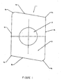
- Figure 1 is a simplified drawing of a top view of a parallelogram-shaped cutting insert showing certain basic elements of the cutting insert;
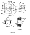
- Figure 2 includes simplified drawings of various views of a parallelogram-shaped cutting insert showing certain basic elements
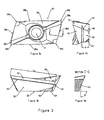
- Figures 3a, 3b, 3c and 3d are views illustrating features of a parallelogram-shaped cutting insert
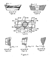
- Figures 4a, 4b, 4c, 4d, 4e and 4f are various views illustrating the pattern of radial rake angles along the main cutting edge and axial rake angles along the minor cutting edge for a parallelogram-shaped cutting insert;
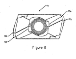
- Figure 5 shows a parallelogram-shaped cutting insert wherein the curve of the main corner nose tangent to the facet edge differs from that of the parallelogram-shaped cutting insert shown in Figure 3 , wherein the main corner nose is truncated by the facet edge;
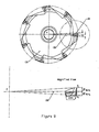
- Figure 6 provides views of one embodiment of a milling cutting tool system according to the present disclosure including seven identical parallelogram-shaped cutting inserts and an associated tool holder;
- Figure 7a is a side view and Figure 7b is a front-end view of an embodiment of a milling cutting tool system according to the present disclosure including seven identical parallelogram-shaped cutting inserts and an associated tool holder;
- Figure 8 provides a front-end view along with a magnified view of one cutting insert of an embodiment of a milling cutting tool system according to the present disclosure including seven identical parallelogram-shaped cutting inserts and an associated tool holder for a milling cutting tool system of this invention with seven identical parallelogram-shaped cutting inserts and an associated tool holder; and
- Figure 9 is a front-end view and a magnified view of an embodiment of a milling cutting tool system according to the present disclosure including seven identical parallelogram-shaped cutting inserts and an associated tool holder.
- Cutting tool life becomes a critical factor in efficient peripheral rotary milling applications for machining difficult-to-machine materials, particularly specialty metals.
- Parallelogram-shaped cutting inserts are typically used in peripheral rotary milling due to their relatively large depth of cut obtained by the relatively longer main cutting edge as compared to square cutting inserts.
- the longer main cutting edge increases the load on the cutting insert.
- Parallelogram-shaped cutting inserts are typically indexable and often comprise a first main cutting edge at the intersection of the top face and the first main radial clearance face and a second cutting edge at the intersection of the top face and the second main radial clearance face.
- Each cutting edge comprises a variable radial rake angle along the length of the cutting edge, comprising a portion having a positive radial rake angle and a portion having a negative radial rake angle.
- Figures 1 and 2 are simplified drawings of parallelogram-shaped cutting inserts showing some basic elements.
- Figure 1 is a top view of parallelogram-shaped cutting insert 1 that includes a center hole 2 for securing the cutting insert 1 to a tool holder; a top face 3 (the top face of a parallelogram-shaped cutting insert may comprise a flat face, an angled flat face, or a curved surface); two main cutting edges 4a and 4b; two minor cutting edges 5a and 5b; two main corner noses 6a and 6b; and two minor corner noses 7a and 7b.
- Figure 2 is a set of drawings of different simplified views of another parallelogram-shaped cutting insert 8 comprising: a top face 9 having rake cutting face 10 (functioning as a chip breaker to promote chip flow/chip breaking during machining); a bottom face 11; two main corner noses 12a and 12b; two main radial cutting edges 13a and 13b; two minor corner noses 14a and 14b; two minor cutting edges 15a and 15b; two radial clearance faces 16a and 16b below the two main cutting edges 13a and 13b; two axial clearance faces 17a and 17b below the two minor cutting edges 15a and 15b; two conical clearance faces 18a and 18b below the main corner noses 12a and 12b; and two conical clearance faces 19a and 19b below the minor corner noses 14a and 14b.
- the radial clearance angle ⁇ RC is formed between the cutting insert center axis 20 and the radial clearance face 16a (or 16b).
- the radial rake angle ⁇ RR is formed between the top flat plane (a plane that is parallel to the bottom surface and intersects the cutting edge) and the rake cutting face 10.
- the axial clearance angle ⁇ AC is formed between the cutting insert center axis 20 and the axial clearance face 17a (or 17b), and the axial rake angle ⁇ AR is formed between the top flat plane and the rake cutting face 10.
- Typical parallelogram-shaped cutting inserts are significantly more complicated than those shown in Figures 1 and 2 , which show only certain basic elements with less detail for the sake of clarity.
- Figure 3 is a set of views illustrating some more detailed features of a parallelogram-shaped cutting insert 27, having a top face 28 with a chip breaker 29, a bottom surface 30, and a center hole 31.
- the cutting insert 27 includes: two main radial cutting edges 32a and 32b (which in this embodiment are curved cutting edges with a relatively large radius); two main corner noses 33a and 33b; two minor corner noses 34a and 34b; and two minor cutting edges, each of which includes two portions, i.e., a first portion 35a (or 35b) connecting to the main corner nose 33a (or 33b) and a second portion 36a (or 36b) connecting to the minor corner nose 34a (or 34b).
- the first portion of the minor radial cutting edge 35a (or 35b), a facet edge may be a line parallel to the bottom face 30.
- the second portion of the minor cutting edge 36a (or 36b) is at an angle to the facet edge 35a (or 35b) and would not usually participate in cutting the material.
- the main corner noses 33a and 33b are at the highest points of the embodiment of cutting insert 27, while the minor corner noses 34a and 34b are at the lowest points, when viewed from the side as shown in Figure 3b .
- the main cutting edges 32a, 32b and the second portion of the minor cutting edges 36a, 36b are not parallel to the bottom surface 30 of the cutting insert 27.
- the effective cutting length of the cutting insert 27 is defined as the length (L E ) as shown in Figure 3b , which is measured parallel to the main cutting edge 32a (or 32b) from the first portion of the minor cutting edge or the facet edge 35a (or 35b) to the intersection point between the main cutting edge 32a (or 32b) and the minor corner noses 34a (or 34b).
- L E determines the maximal depth of cut of a parallelogram-shaped cutting insert when seated in a tool holder.
- Cutting insert 27 has multiple (i.e., at least two) clearance faces below each of the cutting edges at the top face 28.
- first axial clearance face 41, or the facet face, below the first portion of the minor cutting edge (35a or 35b) functions as a wiper contact face to improve the surface finish of the work materials in peripheral rotary milling operations (see Figure 3c ).
- the upper second axial clearance face 42 (see below) is formed right below the second portion of the minor cutting edge (36a or 36b).
- a parallelogram-shaped cutting insert comprises a notch 43 that extends across the entire second axial clearance face and separates it into an upper second axial clearance face 42 and a lower second axial clearance face 45.
- the notch 43 may form an angle A with respect to the bottom face 30. Angle A is 0 degrees in the embodiment shown in Figure 3c (i.e., notch 43 is parallel to bottom face 30), but in certain embodiments may be up to 20 degrees.
- the notch is also grooved into the second axial clearance face at an angle B (see the cross-sectional view in Figure 3d ) ranging from, for example, 90 to 105 degrees with respect to the bottom face 30.
- a function of the notch 43 is to prevent the cutting insert 27 from slipping inside the pocket on a tool holder.
- the axial clearance faces 46 and 47 provide additional clearance for the cutting insert 27 in a tool holder.
- Cutting insert 27 On the main side of the cutting insert 27 shown in Figure 3b , there are multiple radial clearance faces: upper radial clearance face 51, providing a cutting clearance angle for the main cutting edge; lower radial clearance face 52, which is a seating support surface for the cutting insert on the tool holder; and radial clearance faces 53 and 54, providing additional clearance for seating the cutting insert 27 in the tool holder.
- Cutting insert 27 also includes a notch 55 across the entire main side of the cutting insert, functioning as a separation between the upper radial clearance face 51 and lower radial clearance face 52. Similar to notch 43, notch 55 may have an angular shape, for example, a triangular or dovetail shape, or may have curved walls and be shaped as a semicircular groove.
- FIG. 4b-f Another feature of the cutting insert 27 is illustrated in the various cross-sectional views of Figures 4b-f , wherein the radial rake angle ( ⁇ RR ) along the main cutting edge 61 a (or 61 b) changes from positive near the main corner nose 62a (or 62b) to negative near the minor corner nose 63a (or 63b).
- Two concave surfaces 64a and 64b are formed near the minor corner noses 63a and 63b, respectively.
- the concave surface 64a (or 64b) is formed on the top face 28 with chip breaker 29 of cutting insert 27 and intersects with the main cutting edge 61a (or 61 b), which in this embodiment is a curved cutting edge with a relatively large radius.
- the rake angle will be zero.
- Certain embodiments of the cutting insert comprising a variable radial rake angle along the length of the cutting edge will not comprise a point where the rake angle is zero.
- the distance measured in cutting insert's top view plane from the minor corner nose to the point at which the rake angle is zero is defined as.
- the distance L N for one embodiment is shown in Figure 4a .
- the length of effective cutting edge (L E in Figure 3b ) may be projected onto the plane of the top view of Figure 4a and defined as L TOP .
- the axial rake angle may be a variable radial rake angle comprising a portion having a positive radial rake angle and a portion having a negative radial rake angle.
- Figure 5 shows another parallelogram-shaped cutting insert 71.
- the cutting insert 71 shown in Figure 5 is different from the cutting insert 27 shown in Figures 3 and 4 at least in that the first portion of the minor cutting edge, or the facet edge, 72a (or 72b) is tangent to the main corner nose 73a (73b).
- Cutting insert 27 ( Figure 3 ) comprises a first portion of the minor cutting edge, or the facet edge, 35a (or 35b) that is not tangent to the main corner nose 33a (or 33b).
- the cutting insert shown in Figure 5 has full main corner noses 73a and 73b, while the cutting insert shown in Figure 3 has truncated main corner noses 33a and 33b.
- a milling cutting tool system for machining difficult-to-machine materials may also be improved by modifying the associated tool holder to optimize how a parallelogram-shaped cutting insert is positioned in the insert pocket.
- a tool holder is provided that maintains a certain quantitative relationship between the geometry of a parallelogram-shaped cutting insert and its position in the associated tool holder to thereby provide balanced and optimized cutting performance for the cutting inserts and the tool holder.
- FIG. 6a and 6b An embodiment of a milling cutting tool system 80 including multiple parallelogram-shaped cutting inserts 81a, 81 b, 81 c, 81 d, 81 e, 81f, 81 g seated in a tool holder 82 is shown in Figures 6a and 6b .
- the tool holder 82 has multiple insert pockets 83 to secure each cutting insert with a fastener, such as screw 84.
- the tool holder 82 may optionally comprise cooling hole 85 and relief surface 86 for each pocket.
- the tool holder 82 together with all cutting inserts rotates about its axial centerline 87.
- Figures 6a and 6b further show radial centerlines 88 and 89 of tool holder 82.
- a peripheral cutting tool comprise a tool holder comprising at least one insert pocket.
- the tool holder may have more than one insert pocket and typically comprises from 2-25 insert pockets.
- a cutting insert must be attached in each pocket.
- the cutting insert comprises a main cutting edge. The inventors have found that the cutting operation may be performed more efficiently if the cutting insert is positioned in the insert pocket of the tool holder such that a midpoint of the main cutting edge is located in a radial plane comprising the axis of rotation of the tool holder.
- tool holder 91 has seven parallelogram-shaped cutting inserts, 92a, 92b, 92c, 92d, 92e, 92f and 92g.
- the axis of rotation 93 of the tool holder 91 shown in the side view of Figure 7a , will appear on end as point P in the front view of Figure 7b .
- the midpoint of the main cutting edge 101 is located in the primary radial plane 102 comprising the axis of rotation 93 (i.e. through the point P in Figure 7b ) of the tool holder 91.
- Secondary radial plane 104 is perpendicular to primary radial plane 102 and includes the axis of rotation 93.
- a support plane including the bottom surface 103 of the cutting insert 92a (or including the bottom surface of the insert pocket of toolholder 91) is also perpendicular to the secondary radial plane 104.
- cutting insert 92d comprises midpoint 111 of the main cutting edge.
- Midpoint 111 is located in the primary radial plane 112 comprising the axis of rotation 93 (i.e., through the point P in Figure 7b ) of the tool holder 91 and, at the same time, a plane including the bottom surface 113 of the cutting insert 92d is perpendicular to the secondary radial plane 114, which also comprises the axis of rotation 93 of the tool holder 91 and is perpendicular to the primary radial plane 112.
- a more balanced and efficient milling operation can be achieved by positioning the cutting inserts in a tool holder in the above-described manner, which can also be mathematically expressed by the following set of equations.
- the best performance is achieved in machining difficult-to-machine specialty metals when a cutting insert wherein the rake angles are designed according to the several equations of above Eq. (1) is seated in the associated tool holder.
- Such a position for the parallelogram-shaped cutting inset can be mathematically defined by applying the following set of equations.
- the projected side view shown in Figure 8 is obtained by rotating the tool holder 121 around the axis of rotation 122, which is collinear with the X axis of the Cartesian coordinate system as illustrated, until the bottom surface 123 of the cutting insert 124 (as an example) is perpendicular to the X-Y plane (equivalent to the secondary radial plane 104 as shown in Figure 7b ) of the Cartesian coordinate system.
- L 1 is the length of the main cutting edge 125 measured from the cutting edge start point D 1 to the midpoint D
- L 2 is the length of the main cutting edge 125 measured from the middle point D to the cutting edge end point D 2
- ⁇ RC-D1 is the radial cutting angle formed between the cutting edge start point D 1 in the radial plane with the center at P and the radial center line 133
- ⁇ RC-D2 is the radial cutting angle formed between the cutting edge end point D 2 in the radial plane with the
- the parallelogram-shaped cutting inserts described herein may be of conventional size and adapted for conventional use in a variety of machining applications. Certain embodiments according to the present disclosure are directed to a tool holder and a unique and quantitative method to determine how to position parallelogram-shaped cutting inserts in the tool holder to achieve optimized performance for the cutting inserts and the tool holder as an entity.
Landscapes
- Engineering & Computer Science (AREA)
- Mechanical Engineering (AREA)
- Milling Processes (AREA)
- Turning (AREA)
- Sampling And Sample Adjustment (AREA)
- Cutting Tools, Boring Holders, And Turrets (AREA)
Claims (11)
- Outil de découpe périphérique, comprenant :un porte-outil (91) comprenant au moins une poche d'insert ; etun insert de découpe (92a) généralement en forme de parallélogramme comprenant une arête de découpe principale (101), dans lequel l'insert de découpe (92a) est positionné dans la poche d'insert du porte-outil (91) de sorte qu'un point médian de l'arête de découpe principale (101) est situé dans un plan radial primaire (102) comprenant l'axe de rotation (93) du porte-outil (91),et dans lequel l'insert de découpe (92a) généralement en forme de parallélogramme comprend :une face supérieure (9) ;des première et seconde faces de débattement radial principales (16a, 16b), coupant chacune la face supérieure (9) ;des première et seconde faces de débattement axial mineures (17a, 17b), coupant chacune la surface supérieure (9) et raccordant les première et seconde faces de débattement radial (16a, 16b) ;une arête de découpe principale (101) à l'intersection de la face supérieure (9) et de la première face de débattement radial principale (16a) ; etun angle de coupe radial variable suivant la longueur de l'arête de découpe principale (101), l'arête de découpe principale (101) comprenant une portion ayant un angle de coupe radial positif et une portion ayant un angle de coupe radial négatif,caractérisé en ce qu'un plan de support comprenant une surface inférieure (103) de la poche d'insert est perpendiculaire à un plan radial secondaire (104) qui comprend l'axe de rotation (93) du porte-outil (91) et est perpendiculaire au plan radial primaire (102).
- Outil de découpe périphérique selon la revendication 1, dans lequel l'angle de coupe radial de l'arête de découpe principale (101) passe d'un angle de coupe radial positif à un angle de coupe radial négatif le long de l'arête de découpe principale (101).
- Outil de découpe périphérique selon la revendication 1, dans lequel l'insert de découpe (92a) généralement en forme de parallélogramme comprend un nez de bec principal (12a).
- Outil de découpe périphérique selon la revendication 1, dans lequel l'angle de coupe radial de l'arête de découpe principale (101) à proximité du nez de bec principal (12a) est positif.
- Outil de découpe périphérique selon la revendication 2, dans lequel la longueur de la portion de l'arête de découpe principale (101) ayant un angle de coupe positif est au moins trois fois plus grande que la longueur de la portion de l'arête de découpe principale (101) ayant un angle de coupe radial négatif.
- Outil de découpe périphérique selon la revendication 1, dans lequel l'insert de découpe (92a) en forme de parallélogramme comprend :une arête de découpe (4a) à l'intersection de la face supérieure (9) et de la première face de débattement radial principale (16a) ; etune arête de découpe (4b) à l'intersection de la face supérieure (9) et de la seconde face de débattement radial principale (16b) ;dans lequel chacune desdites arêtes de découpe a un angle de coupe radial variable suivant la longueur de l'arête de découpe, chacune desdites arêtes de découpe comprenant une portion ayant un angle de coupe radial positif et une portion ayant un angle de coupe radial négatif.
- Procédé de positionnement d'un insert de découpe (92a) généralement en forme de parallélogramme comprenant une arête de découpe principale (101) dans une poche d'insert d'un porte-outil (91) d'un outil de découpe périphérique, le procédé comprenant :le positionnement de l'insert de découpe (92a) dans la poche d'insert de sorte qu'un point médian de l'arête de découpe principale (101) est situé dans un plan radial primaire (102) comprenant l'axe de rotation (93) du porte-outil (91) ;caractérisé en ce qu'un plan de support comprenant une surface inférieure (103) de la poche d'insert est perpendiculaire à un plan radial secondaire (104) qui comprend l'axe de rotation (93) du porte-outil (91) et est perpendiculaire au plan radial primaire (102) ; et dans lequel l'insert de découpe (92a) généralement en forme de parallélogramme comprend :une face supérieure (9) ;des première et seconde faces de débattement radial (16a, 16b), chacune coupant la face supérieure (9) ;des première et seconde faces de débattement axial mineures (17a, 17b), chacune coupant la face supérieure (9) et raccordant les première et seconde faces de débattement radial principales (16a, 16b) ;une arête de découpe principale (101) à l'intersection de la face supérieure (9) et de la première face de débattement radial principale (16a) ; etun angle de coupe radial variable suivant la longueur de l'arête de découpe principale (101), l'arête de découpe principale (101) comprenant une portion ayant un angle de coupe radial positif et une portion ayant un angle de coupe radial négatif.
- Procédé selon la revendication 7, dans lequel l'angle de coupe radial de l'arête de découpe principale (101) passe d'un angle de coupe radial positif à un angle de coupe radial négatif le long de l'arête de découpe principale (101).
- Procédé selon la revendication 7, dans lequel l'insert de découpe (92a) généralement en forme de parallélogramme comprend un nez de bec principal (12a).
- Procédé selon la revendication 7, dans lequel l'angle de coupe radial de l'arête de découpe principale (101) à proximité du nez de bec principal (12a) est positif.
- Procédé selon la revendication 7, dans lequel la longueur de la portion de l'arête de découpe principale (101) ayant un angle de coupe radial positif est au moins trois fois plus longue que la longueur de la portion de l'arête de découpe principale (101) ayant un angle de coupe radial négatif.
Priority Applications (1)
| Application Number | Priority Date | Filing Date | Title |
|---|---|---|---|
| PL09004574T PL2077174T3 (pl) | 2007-01-16 | 2007-12-07 | Uchwyt narzędziowy do wkładki skrawającej oraz powiązany z nim sposób |
Applications Claiming Priority (3)
| Application Number | Priority Date | Filing Date | Title |
|---|---|---|---|
| US88505307P | 2007-01-16 | 2007-01-16 | |
| US11/743,803 US7905687B2 (en) | 2007-01-16 | 2007-05-03 | Cutting insert, tool holder, and related method |
| EP07865350.8A EP2064015B1 (fr) | 2007-01-16 | 2007-12-07 | Insert de coupe, porte-outil et procédé correspondant |
Related Parent Applications (3)
| Application Number | Title | Priority Date | Filing Date |
|---|---|---|---|
| EP07865350.8 Division | 2007-12-07 | ||
| EP07865350.8A Division-Into EP2064015B1 (fr) | 2007-01-16 | 2007-12-07 | Insert de coupe, porte-outil et procédé correspondant |
| EP07865350.8A Division EP2064015B1 (fr) | 2007-01-16 | 2007-12-07 | Insert de coupe, porte-outil et procédé correspondant |
Publications (2)
| Publication Number | Publication Date |
|---|---|
| EP2077174A1 EP2077174A1 (fr) | 2009-07-08 |
| EP2077174B1 true EP2077174B1 (fr) | 2012-04-25 |
Family
ID=39617914
Family Applications (2)
| Application Number | Title | Priority Date | Filing Date |
|---|---|---|---|
| EP09004574A Active EP2077174B1 (fr) | 2007-01-16 | 2007-12-07 | Support d'outil d'insert de découpage, et procédé associé |
| EP07865350.8A Active EP2064015B1 (fr) | 2007-01-16 | 2007-12-07 | Insert de coupe, porte-outil et procédé correspondant |
Family Applications After (1)
| Application Number | Title | Priority Date | Filing Date |
|---|---|---|---|
| EP07865350.8A Active EP2064015B1 (fr) | 2007-01-16 | 2007-12-07 | Insert de coupe, porte-outil et procédé correspondant |
Country Status (16)
| Country | Link |
|---|---|
| US (1) | US7905687B2 (fr) |
| EP (2) | EP2077174B1 (fr) |
| JP (1) | JP5451400B2 (fr) |
| KR (1) | KR101262440B1 (fr) |
| CN (1) | CN101522351B (fr) |
| AT (1) | ATE554872T1 (fr) |
| BR (1) | BRPI0716534A2 (fr) |
| CA (1) | CA2663654C (fr) |
| DK (1) | DK2077174T3 (fr) |
| IL (2) | IL197342A (fr) |
| MX (1) | MX2009002840A (fr) |
| PL (1) | PL2077174T3 (fr) |
| PT (1) | PT2077174E (fr) |
| RU (1) | RU2465105C2 (fr) |
| TW (1) | TWI343846B (fr) |
| WO (1) | WO2008088621A2 (fr) |
Families Citing this family (35)
| Publication number | Priority date | Publication date | Assignee | Title |
|---|---|---|---|---|
| US7220083B2 (en) * | 2003-10-15 | 2007-05-22 | Tdy Industries, Inc. | Cutting insert for high feed face milling |
| CN101678465B (zh) * | 2007-05-28 | 2012-02-08 | 京瓷株式会社 | 切削镶刀及切削工具、以及使用了该切削工具的切削方法 |
| CN101959633B (zh) * | 2008-02-27 | 2014-04-16 | 京瓷株式会社 | 钻头用切削镶刀和钻头、以及使用其的切削方法 |
| US7905689B2 (en) * | 2008-05-07 | 2011-03-15 | Tdy Industries, Inc. | Cutting tool system, cutting insert, and tool holder |
| US8491234B2 (en) * | 2009-02-12 | 2013-07-23 | TDY Industries, LLC | Double-sided cutting inserts for high feed milling |
| US7976250B2 (en) * | 2009-02-12 | 2011-07-12 | Tdy Industries, Inc. | Double-sided cutting inserts for high feed milling |
| US9586264B2 (en) * | 2009-04-28 | 2017-03-07 | Kennametal Inc. | Double-sided cutting insert for drilling tool |
| JP5346373B2 (ja) * | 2009-06-26 | 2013-11-20 | 京セラ株式会社 | 切削インサート及び切削工具、並びにそれを用いた切削加工物の製造方法 |
| US8807884B2 (en) * | 2009-12-18 | 2014-08-19 | Kennametal Inc. | Tool holder for multiple differently-shaped cutting inserts |
| SE535147C2 (sv) * | 2009-12-18 | 2012-04-24 | Sandvik Intellectual Property | Anordning för fräsning av material |
| FR2972948B1 (fr) * | 2011-03-22 | 2014-04-11 | Renault Sa | Procede et dispositif de fraisage surfacage |
| US9387544B2 (en) | 2011-05-02 | 2016-07-12 | Fairfield Manufacturing Company, Inc. | Smilled spline apparatus and smilling process for manufacturing the smilled spline apparatus |
| CN103702789B (zh) | 2011-07-22 | 2018-06-08 | 钴碳化钨硬质合金印度有限公司 | 可转位的钻头镶片 |
| DE102012014092B4 (de) | 2011-07-22 | 2020-12-17 | Kennametal India Ltd. | Indexierbarer Bohreinsatz sowie Bohrkörper mit indexierbarem Bohreinsatz |
| DE102012012980B4 (de) | 2011-07-22 | 2019-10-17 | Kennametal India Ltd. | Bohrwerkzeug |
| JP5906976B2 (ja) * | 2011-10-04 | 2016-04-20 | 三菱マテリアル株式会社 | 切削インサートおよび刃先交換式切削工具 |
| DE102012104082A1 (de) * | 2012-05-09 | 2013-11-14 | Walter Ag | Wendeschneidplatte für Eckfräser |
| CN103447591B (zh) | 2012-05-28 | 2020-02-28 | 钴碳化钨硬质合金印度有限公司 | 四角形的可转位的钻头镶片 |
| US9283626B2 (en) | 2012-09-25 | 2016-03-15 | Kennametal Inc. | Double-sided cutting inserts with anti-rotation features |
| US9011049B2 (en) | 2012-09-25 | 2015-04-21 | Kennametal Inc. | Double-sided cutting inserts with anti-rotation features |
| WO2014116571A1 (fr) | 2013-01-23 | 2014-07-31 | Kennametal India Limited | Plaquette amovible indexée et outil de coupe rotatif la mettant en œuvre |
| CN105764640B (zh) | 2013-09-11 | 2017-09-15 | 三菱日立工具技术株式会社 | 刀头更换式旋转切削工具 |
| US9358622B2 (en) | 2013-11-21 | 2016-06-07 | Iscar, Ltd. | Single sided indexable ramping milling insert and ramping milling tool |
| USD738412S1 (en) * | 2013-12-25 | 2015-09-08 | Taegutec Ltd. | Cutting insert |
| CN103934496B (zh) * | 2014-05-12 | 2016-05-11 | 哈尔滨理工大学 | 一种复杂型腔加工用的仿形铣削刀具 |
| USD752664S1 (en) * | 2014-09-25 | 2016-03-29 | Taegutec Ltd. | Cutting insert |
| EP3050655B1 (fr) | 2015-01-30 | 2017-03-22 | Sandvik Intellectual Property AB | Insert de fraisage et outil de fraisage |
| US10058933B2 (en) | 2015-04-03 | 2018-08-28 | The Boeing Company | Orbital cutting tool having cutting edges with axially varying circumferential spacing |
| US9981323B2 (en) * | 2015-07-16 | 2018-05-29 | Kennametal Inc. | Double-sided tangential cutting insert and cutting tool system using the same |
| US9993884B2 (en) * | 2015-07-16 | 2018-06-12 | Kennametal Inc. | Double-sided tangential cutting insert |
| US9889510B2 (en) | 2016-01-05 | 2018-02-13 | The Boeing Company | Variable rake fatigue enhancing orbital drilling cutter |
| US10953481B2 (en) | 2016-03-13 | 2021-03-23 | The Boeing Company | Machining/burnishing dual geometry orbital drilling tool |
| CN110023015B (zh) * | 2016-12-09 | 2020-07-03 | 三菱日立工具株式会社 | 切削刀片及可转位刀片式旋转切削工具 |
| JP6869492B2 (ja) * | 2019-08-28 | 2021-05-12 | 株式会社タンガロイ | 切削インサート |
| WO2022049659A1 (fr) * | 2020-09-02 | 2022-03-10 | 住友電工ハードメタル株式会社 | Plaquette de coupe pour outil de coupe rotatif et outil de coupe rotatif |
Family Cites Families (129)
| Publication number | Priority date | Publication date | Assignee | Title |
|---|---|---|---|---|
| US3399442A (en) * | 1966-09-08 | 1968-09-03 | Kennametal Inc | Cutting insert |
| US3557416A (en) * | 1968-08-16 | 1971-01-26 | Kennametal Inc | Cutting insert |
| US3621549A (en) * | 1970-03-06 | 1971-11-23 | James O Billups | Cutting tool insert assembly |
| US3806713A (en) * | 1971-10-21 | 1974-04-23 | Honeywell Inf Systems | Method and apparatus for maximizing the length of straight line segments approximating a curve |
| JPS5950450B2 (ja) | 1976-02-25 | 1984-12-08 | ダイジヱツト工業株式会社 | スロ−アウエイチツプ |
| FR2364724A1 (fr) | 1976-09-17 | 1978-04-14 | Walter Gmbh Montanwerke | Plaquette de coupe indexable pour outil de fraisage, et outil de fraisage equipe de telles plaquettes |
| SU814573A1 (ru) | 1978-07-31 | 1981-03-25 | Ярославский Политехническийинститут | Многопозиционна режуща пласти-HA |
| US4274766A (en) * | 1979-11-28 | 1981-06-23 | The Valeron Corporation | Cutter assembly for broaching |
| US4292365A (en) * | 1980-01-21 | 1981-09-29 | Owens-Corning Fiberglas Corporation | Polymeric mats having continuous filaments with an asymmetrical cross-sectional shape |
| US4294565A (en) | 1980-03-06 | 1981-10-13 | General Electric Company | Indexable finishing insert for a milling cutter |
| US4595322A (en) * | 1981-08-10 | 1986-06-17 | Burke Clement | Spade drill bit |
| DE3200191A1 (de) | 1982-01-07 | 1983-07-14 | Otto 8961 Reicholzried Zettl | "fraeswerkzeug" |
| DE3204210C2 (de) * | 1982-02-08 | 1986-04-03 | Stellram GmbH, 6056 Heusenstamm | Bohrwerkzeug für metallische Werkstoffe |
| US4659264A (en) * | 1982-07-06 | 1987-04-21 | Kennametal Inc. | Drill and indexable carbide insert therefor |
| JPS59214501A (ja) | 1983-05-23 | 1984-12-04 | Toshiba Corp | 切削工具 |
| SU1278110A1 (ru) * | 1984-01-31 | 1986-12-23 | Государственное Проектное Конструкторско-Технологическое Бюро Машиностроения Научно-Производственного Объединения "Технолог" | Инструментальна головка |
| JPH0131371Y2 (fr) * | 1985-06-06 | 1989-09-26 | ||
| DE3618574C2 (de) | 1985-06-06 | 1989-11-02 | Mitsubishi Kinzoku K.K., Tokio/Tokyo, Jp | Positiv-wendeschneidplatte |
| SE448431B (sv) * | 1985-07-03 | 1987-02-23 | Santrade Ltd | Vendsker for spanavskiljande bearbetning |
| CH667407A5 (fr) * | 1986-03-27 | 1988-10-14 | Stellram Sa | Fraise a plaquettes de coupe amovibles. |
| US4760548A (en) * | 1986-06-13 | 1988-07-26 | International Business Machines Corporation | Method and apparatus for producing a curve image |
| JPH0782554B2 (ja) | 1986-09-10 | 1995-09-06 | フアナツク株式会社 | 曲面加工方法 |
| SU1504006A1 (ru) | 1987-11-30 | 1989-08-30 | В.Г. Чернавский, В.Г. Дигтенко, А.И. Дронов и Т.Б. Грищенко | Режуща пластина |
| IL93883A (en) * | 1989-04-12 | 1993-02-21 | Iscar Ltd | Cutting insert for a milling cutting tool |
| US5094572A (en) * | 1989-12-04 | 1992-03-10 | Thomas Grismer | Spade drill for hard material |
| US5137398A (en) * | 1990-04-27 | 1992-08-11 | Sumitomo Electric Industries, Ltd. | Drill bit having a diamond-coated sintered body |
| GB9010769D0 (en) * | 1990-05-14 | 1990-07-04 | Iscar Hartmetall | Cutting insert |
| US5244318A (en) * | 1990-07-04 | 1993-09-14 | Mitsubishi Materials Corporation | Throwaway insert and cutting tool therefor |
| US5333972A (en) * | 1990-10-04 | 1994-08-02 | Valenite Inc. | Special boring insert |
| US5232319A (en) | 1990-10-25 | 1993-08-03 | Iscar Ltd. | Insert for a milling cutter |
| SE500310C2 (sv) * | 1990-12-03 | 1994-05-30 | Sandvik Ab | Skär och verktyg för skalsvarvning |
| US5092718A (en) * | 1990-12-10 | 1992-03-03 | Metal Cutting Tools Corp. | Drill with replaceable cutting inserts |
| SE467727B (sv) * | 1991-01-28 | 1992-09-07 | Sandvik Ab | Borr med minst tvaa skaer, samt med symmetrisk borrspets och olika laanga skaereggar |
| JP3057781B2 (ja) * | 1991-03-07 | 2000-07-04 | 三菱マテリアル株式会社 | スローアウェイチップ |
| US5338135A (en) * | 1991-04-11 | 1994-08-16 | Sumitomo Electric Industries, Ltd. | Drill and lock screw employed for fastening the same |
| US5408598A (en) * | 1991-05-23 | 1995-04-18 | International Business Machines Corporation | Method for fast generation of parametric curves employing a pre-calculated number of line segments in accordance with a determined error threshold |
| DE4118065C2 (de) | 1991-06-01 | 1994-09-01 | Krupp Widia Gmbh | Vieleckiger oder runder Schneideinsatz |
| DE4118070C2 (de) | 1991-06-01 | 1995-02-09 | Widia Heinlein Gmbh | Werkzeug für die spanende Bearbeitung |
| US5377116A (en) * | 1991-07-01 | 1994-12-27 | Valenite Inc. | Method and system for designing a cutting tool |
| US5226761A (en) * | 1991-09-27 | 1993-07-13 | Iscar Ltd. | Metal cutting insert and metal cutting tool utilizing the metal cutting insert |
| US5203649A (en) * | 1991-10-07 | 1993-04-20 | Gte Valentine Corporation | High productivity, high metal removal rate insert |
| DE4141368A1 (de) * | 1991-12-14 | 1993-06-17 | Krupp Widia Gmbh | Schneideinsatz |
| CA2062213C (fr) * | 1992-03-03 | 1996-07-16 | Alfonso Minicozzi | Plaquette amovible pour outils de deroulage |
| JPH0615517A (ja) * | 1992-07-01 | 1994-01-25 | Sumitomo Electric Ind Ltd | スローアウェイチップ及び正面フライスカッタ |
| IL103115A (en) | 1992-09-09 | 1996-09-12 | Iscar Ltd | Milling placement |
| US5346336A (en) * | 1992-11-04 | 1994-09-13 | Sandvik, Inc. | Metal-cutting insert having a round cutting edge |
| DE4239236C2 (de) | 1992-11-21 | 1997-06-26 | Widia Gmbh | Schneideinsatz |
| JPH06218618A (ja) * | 1993-01-21 | 1994-08-09 | Mitsubishi Materials Corp | スローアウェイチップ |
| SE500722C2 (sv) | 1993-01-27 | 1994-08-15 | Sandvik Ab | Skär med vriden spånyta |
| JP3196394B2 (ja) * | 1993-02-01 | 2001-08-06 | 三菱マテリアル株式会社 | スローアウェイチップ |
| US5725334A (en) * | 1993-03-29 | 1998-03-10 | Widia Gmbh | Cutting insert |
| EP0625395B1 (fr) * | 1993-05-10 | 1995-04-19 | STELLRAM GmbH | Outil de perçage pour matériaux métalliques |
| JPH08507976A (ja) | 1993-06-25 | 1996-08-27 | ケンナメタル インコーポレイテッド | 改良された表面粗さのためのインサートコーナー幾何学的形状 |
| US5388932A (en) * | 1993-09-13 | 1995-02-14 | Kennametal Inc. | Cutting insert for a milling cutter |
| JP3166022B2 (ja) * | 1993-12-28 | 2001-05-14 | 三菱マテリアル株式会社 | スローアウェイチップおよびその製造方法 |
| DE4400538A1 (de) | 1994-01-11 | 1995-07-13 | Gustav Werthwein | Fräswerkzeug |
| KR100344370B1 (ko) * | 1994-01-14 | 2002-09-18 | 산드빅 악티에볼라그 | 정밀밀링용인덱스가능한삽입체및그를위한커터본체 |
| SE509224C2 (sv) | 1994-05-19 | 1998-12-21 | Sandvik Ab | Vändskär |
| DE4430171C2 (de) * | 1994-08-25 | 1996-08-14 | Walter Ag | Formschlüssig gesicherte Schneidplatte |
| IL110785A (en) * | 1994-08-25 | 1998-04-05 | Iscar Ltd | Put a spinner for a rotary milling tool |
| IL111367A0 (en) * | 1994-10-23 | 1994-12-29 | Iscar Ltd | An exchangeable cutting insert |
| US5791833A (en) * | 1994-12-29 | 1998-08-11 | Kennametal Inc. | Cutting insert having a chipbreaker for thin chips |
| JP3109561B2 (ja) * | 1995-03-08 | 2000-11-20 | 住友電気工業株式会社 | スローアウェイチップ及び切削工具 |
| US5807031A (en) | 1995-03-10 | 1998-09-15 | Mitsubishi Materials Corp. | Throw-away tip and throw-away type cutter |
| JPH08261167A (ja) * | 1995-03-24 | 1996-10-08 | Toyota Autom Loom Works Ltd | 圧縮機 |
| DE19516893A1 (de) | 1995-05-09 | 1996-11-14 | Widia Gmbh | Schneideinsatz und Fräswerkzeug |
| SE506679C2 (sv) * | 1995-06-21 | 1998-01-26 | Seco Tools Ab | Skärverktyg, företrädesvis för fräsning |
| JP3634909B2 (ja) * | 1995-11-27 | 2005-03-30 | 京セラ株式会社 | ドリルインサート |
| JPH09216113A (ja) * | 1996-02-13 | 1997-08-19 | Sumitomo Electric Ind Ltd | スローアウェイチップおよび切削工具 |
| IL118797A (en) * | 1996-07-05 | 1999-10-28 | Iscar Ltd | Cutting insert |
| US6100904A (en) * | 1997-06-25 | 2000-08-08 | Adobe Systems Incorporated | Curvature smoothing |
| SE512253C2 (sv) * | 1997-06-30 | 2000-02-21 | Sandvik Ab | Vändskär |
| IL123685A (en) * | 1998-03-16 | 2001-09-13 | Iscar Ltd | Modular cutting tool dispenser |
| SE512040C2 (sv) | 1998-05-06 | 2000-01-17 | Sandvik Ab | Vändskär för pinnfräsar |
| RU2138371C1 (ru) * | 1998-06-26 | 1999-09-27 | Алтайский государственный технический университет им.И.И.Ползунова | Фреза |
| US5957635A (en) * | 1998-08-21 | 1999-09-28 | Allied Machine & Engineering Corp. | Drill tool assembly |
| SE514032C2 (sv) * | 1998-09-08 | 2000-12-11 | Seco Tools Ab | Verktyg och skär för fräsning |
| US6238133B1 (en) * | 1998-10-20 | 2001-05-29 | Kennametal Pc Inc. | Anti-rotation mounting mechanism for round cutting insert |
| US6186705B1 (en) * | 1999-02-23 | 2001-02-13 | Ingersoll Cutting Tool Company | Cutting insert with chip control |
| US6050752A (en) * | 1999-03-19 | 2000-04-18 | Kennametal Inc. | Cutting insert |
| JP4465809B2 (ja) * | 1999-07-09 | 2010-05-26 | 三菱マテリアル株式会社 | スローアウェイチップ |
| SE515070C2 (sv) * | 1999-10-22 | 2001-06-05 | Sandvik Ab | Dubbelnegativt skär till verktyg för spånavskiljande bearbetning |
| US6270297B1 (en) * | 2000-01-28 | 2001-08-07 | Ati Properties, Inc. | Cutting tools and drill inserts with chip control geometry |
| SE519575C2 (sv) * | 2000-04-11 | 2003-03-18 | Sandvik Ab | Borrdkär för metallborrning |
| DE10018452A1 (de) * | 2000-04-13 | 2001-10-25 | Widia Gmbh | Schneideinsatz |
| JP4576735B2 (ja) | 2000-05-23 | 2010-11-10 | 三菱マテリアル株式会社 | スローアウェイチップ及びスローアウェイ式カッタ |
| KR100387406B1 (ko) * | 2000-08-29 | 2003-06-18 | 한국야금 주식회사 | 곡선 절인을 가진 절삭인서트 |
| US6684742B1 (en) * | 2000-10-19 | 2004-02-03 | Keith Alan White | Machining apparatuses and methods of use |
| EP1205877A1 (fr) | 2000-11-14 | 2002-05-15 | Honda R&D Europe (Deutschland) GmbH | Fonctions d'adaptation approximative |
| US6769844B2 (en) * | 2001-01-10 | 2004-08-03 | Kennametal Inc. | Cutting insert and method of making the same |
| IL141089A (en) * | 2001-01-25 | 2006-08-20 | Amir Satran | Put a spin |
| JP4228557B2 (ja) * | 2001-02-05 | 2009-02-25 | 三菱マテリアル株式会社 | スローアウェイチップ |
| JP2002301603A (ja) | 2001-04-02 | 2002-10-15 | Manabe Seisakusho:Kk | スローアウェイ切削チップ、切削チップホルダ及びスローアウェイ切削チップの位置決め方法 |
| US6540448B2 (en) * | 2001-05-14 | 2003-04-01 | Ingersoll Cutting Tool Company | Cutting tool with improved insert seat arrangement for indexable cutting inserts |
| KR100916280B1 (ko) * | 2001-05-25 | 2009-09-10 | 히타치 쓰루 가부시키가이샤 | 날끝 교환식 회전 공구 |
| US6503028B1 (en) | 2001-06-15 | 2003-01-07 | Sandvik Aktiebolag | Sintered cutting insert having center hole for clamp screw |
| JP4797292B2 (ja) * | 2001-07-17 | 2011-10-19 | 株式会社タンガロイ | スローアウェイ式エンドミルおよび切刃チップ |
| US6623217B2 (en) * | 2001-09-24 | 2003-09-23 | Valenite, Inc. | Indexable turning insert |
| SE523617C2 (sv) * | 2001-10-01 | 2004-05-04 | Sandvik Ab | Skär för spånavskiljande bearbetning försedd med spånbrytande geometri |
| JP3775321B2 (ja) | 2002-03-20 | 2006-05-17 | 三菱マテリアル株式会社 | スローアウェイチップおよびスローアウェイ式切削工具 |
| JP3951766B2 (ja) | 2002-03-20 | 2007-08-01 | 三菱マテリアル株式会社 | スローアウェイチップおよびスローアウェイ式切削工具 |
| US20030206777A1 (en) * | 2002-05-03 | 2003-11-06 | Gyllengahm Ulf Stefan | Metal cutting insert having straight cutting edge and curved abutment surface |
| SE525241C2 (sv) | 2002-05-29 | 2005-01-11 | Sandvik Ab | Borrverktygsats, borrverktyg samt indexerbart borrskär härför |
| IL150015A (en) * | 2002-06-04 | 2007-06-17 | Amir Satran | Cutting insert and milling cutter |
| DE10225070A1 (de) * | 2002-06-06 | 2004-01-15 | Hilti Ag | Kernbohrkrone mit geometrisch definierten Schneidelementen |
| EP1375037A1 (fr) * | 2002-06-25 | 2004-01-02 | Ngk Spark Plug Co., Ltd | Plaquette de coupe, porte-outil et outil de coupe |
| SE525878C2 (sv) * | 2002-10-10 | 2005-05-17 | Seco Tools Ab | Fräsverktyg och indexerbart skär med parallella sidor |
| JP4121449B2 (ja) * | 2003-01-16 | 2008-07-23 | 日本特殊陶業株式会社 | スローアウェイチップ及びバイト |
| DE10312922B4 (de) * | 2003-03-22 | 2006-02-16 | Walter Ag | Schneidplatte und Fräswerkzeug |
| JP4351460B2 (ja) * | 2003-03-25 | 2009-10-28 | 京セラ株式会社 | スローアウェイエンドミル |
| US7722297B2 (en) * | 2003-04-15 | 2010-05-25 | Tdy Industries, Inc. | Antirotation tool holder and cutting insert |
| DE10317760B4 (de) * | 2003-04-17 | 2005-08-25 | Walter Ag | Fräswerkzeug und Schneidplatte für ein solches |
| KR100556681B1 (ko) * | 2003-04-28 | 2006-03-07 | 대구텍 주식회사 | 다기능 절삭 가공용 툴홀더 조립체 |
| US7234899B2 (en) * | 2003-05-19 | 2007-06-26 | Tdy Industries, Inc. | Cutting tool having a wiper nose corner |
| DE10326662A1 (de) * | 2003-06-11 | 2005-01-05 | Sandvik Ab | Schneideinsatz zum Drehen und Fräsen |
| US7220083B2 (en) * | 2003-10-15 | 2007-05-22 | Tdy Industries, Inc. | Cutting insert for high feed face milling |
| IL160223A (en) * | 2004-02-04 | 2008-11-26 | Carol Smilovici | Double-sided cutting insert and milling cutter |
| US7070363B2 (en) * | 2004-07-15 | 2006-07-04 | Kennametal Inc. | Cutting insert for high-speed milling cutter |
| SE527617C8 (sv) | 2004-09-06 | 2006-06-13 | Sandvik Intellectual Property | Fräsverktyg, skär för fräsverktyg samt solitt fräsverktyg |
| US7325471B2 (en) * | 2004-09-07 | 2008-02-05 | Kennametal Inc. | Toolholder and cutting insert for a toolholder assembly |
| US7452167B2 (en) * | 2004-11-26 | 2008-11-18 | Kyocera Corporation | Cutting insert and milling tool |
| RU2318634C2 (ru) * | 2005-04-13 | 2008-03-10 | Валентин Алексеевич Настасенко | Торцовая режущая, режуще-деформирующая и деформирующая фреза, рабочие пластины к ней и способ их изготовления, способ обработки деформирующей фрезой |
| DE102005025815A1 (de) * | 2005-06-02 | 2006-12-07 | Kennametal Widia Produktions Gmbh & Co. Kg | Schneideinsatz, insbesondere zur Kurbelwellenbearbeitung |
| IL169491A (en) * | 2005-06-30 | 2009-06-15 | Carol Smilovici | Cutting insert |
| JP4231496B2 (ja) | 2005-08-01 | 2009-02-25 | 住友電工ハードメタル株式会社 | スローアウェイチップ |
| JP2007044782A (ja) * | 2005-08-08 | 2007-02-22 | Sumitomo Electric Hardmetal Corp | スローアウェイチップ及びそれを用いたミーリングカッタ |
| IL182343A0 (en) * | 2007-04-01 | 2007-07-24 | Iscar Ltd | Cutting insert and tool for milling and ramping at high feed rates |
| US7905689B2 (en) * | 2008-05-07 | 2011-03-15 | Tdy Industries, Inc. | Cutting tool system, cutting insert, and tool holder |
| US7976250B2 (en) * | 2009-02-12 | 2011-07-12 | Tdy Industries, Inc. | Double-sided cutting inserts for high feed milling |
-
2007
- 2007-05-03 US US11/743,803 patent/US7905687B2/en not_active Expired - Fee Related
- 2007-12-06 TW TW096146633A patent/TWI343846B/zh not_active IP Right Cessation
- 2007-12-07 MX MX2009002840A patent/MX2009002840A/es active IP Right Grant
- 2007-12-07 KR KR1020097004657A patent/KR101262440B1/ko not_active IP Right Cessation
- 2007-12-07 EP EP09004574A patent/EP2077174B1/fr active Active
- 2007-12-07 CA CA2663654A patent/CA2663654C/fr not_active Expired - Fee Related
- 2007-12-07 RU RU2009111888/02A patent/RU2465105C2/ru not_active IP Right Cessation
- 2007-12-07 PL PL09004574T patent/PL2077174T3/pl unknown
- 2007-12-07 DK DK09004574.1T patent/DK2077174T3/da active
- 2007-12-07 PT PT09004574T patent/PT2077174E/pt unknown
- 2007-12-07 AT AT09004574T patent/ATE554872T1/de active
- 2007-12-07 BR BRPI0716534-0A2A patent/BRPI0716534A2/pt not_active IP Right Cessation
- 2007-12-07 EP EP07865350.8A patent/EP2064015B1/fr active Active
- 2007-12-07 CN CN2007800365263A patent/CN101522351B/zh not_active Expired - Fee Related
- 2007-12-07 WO PCT/US2007/086717 patent/WO2008088621A2/fr active Application Filing
- 2007-12-07 JP JP2009545548A patent/JP5451400B2/ja not_active Expired - Fee Related
-
2009
- 2009-03-02 IL IL197342A patent/IL197342A/en not_active IP Right Cessation
-
2013
- 2013-06-20 IL IL227059A patent/IL227059A/en not_active IP Right Cessation
Also Published As
| Publication number | Publication date |
|---|---|
| US7905687B2 (en) | 2011-03-15 |
| EP2064015B1 (fr) | 2016-08-17 |
| RU2465105C2 (ru) | 2012-10-27 |
| JP2010515591A (ja) | 2010-05-13 |
| TWI343846B (en) | 2011-06-21 |
| WO2008088621A3 (fr) | 2008-10-09 |
| MX2009002840A (es) | 2009-06-04 |
| DK2077174T3 (da) | 2012-07-30 |
| KR20090110817A (ko) | 2009-10-22 |
| PT2077174E (pt) | 2012-06-25 |
| TW200833442A (en) | 2008-08-16 |
| CN101522351A (zh) | 2009-09-02 |
| IL197342A0 (en) | 2009-12-24 |
| IL197342A (en) | 2013-11-28 |
| CA2663654A1 (fr) | 2008-07-24 |
| EP2064015A2 (fr) | 2009-06-03 |
| US20080170919A1 (en) | 2008-07-17 |
| CN101522351B (zh) | 2012-02-01 |
| RU2009111888A (ru) | 2010-10-10 |
| JP5451400B2 (ja) | 2014-03-26 |
| IL227059A (en) | 2014-09-30 |
| BRPI0716534A2 (pt) | 2013-09-24 |
| CA2663654C (fr) | 2013-07-16 |
| WO2008088621A2 (fr) | 2008-07-24 |
| PL2077174T3 (pl) | 2012-09-28 |
| KR101262440B1 (ko) | 2013-05-08 |
| ATE554872T1 (de) | 2012-05-15 |
| EP2077174A1 (fr) | 2009-07-08 |
Similar Documents
| Publication | Publication Date | Title |
|---|---|---|
| EP2077174B1 (fr) | Support d'outil d'insert de découpage, et procédé associé | |
| EP1689548B1 (fr) | Plaquette de coupe pour fraisage en bout a vitesse d'avance elevee | |
| EP2396133B1 (fr) | Inserts de coupe à double côté pour fraisage à grande vitesse | |
| EP2101947B1 (fr) | Insert de coupe et outil de coupe | |
| JP2010515591A5 (fr) | ||
| EP0585871A1 (fr) | Plaquette de coupe pour une fraise | |
| IL270419B1 (en) | A cutting application with a split cutting edge that has a front and trailing edge component |
Legal Events
| Date | Code | Title | Description |
|---|---|---|---|
| PUAI | Public reference made under article 153(3) epc to a published international application that has entered the european phase |
Free format text: ORIGINAL CODE: 0009012 |
|
| 17P | Request for examination filed |
Effective date: 20090416 |
|
| AC | Divisional application: reference to earlier application |
Ref document number: 2064015 Country of ref document: EP Kind code of ref document: P |
|
| AK | Designated contracting states |
Kind code of ref document: A1 Designated state(s): AT BE BG CH CY CZ DE DK EE ES FI FR GB GR HU IE IS IT LI LT LU LV MC MT NL PL PT RO SE SI SK TR |
|
| AX | Request for extension of the european patent |
Extension state: AL BA HR MK RS |
|
| 17Q | First examination report despatched |
Effective date: 20091104 |
|
| AKX | Designation fees paid |
Designated state(s): AT BE BG CH CY CZ DE DK EE ES FI FR GB GR HU IE IS IT LI LT LU LV MC MT NL PL PT RO SE SI SK TR |
|
| GRAP | Despatch of communication of intention to grant a patent |
Free format text: ORIGINAL CODE: EPIDOSNIGR1 |
|
| GRAS | Grant fee paid |
Free format text: ORIGINAL CODE: EPIDOSNIGR3 |
|
| GRAA | (expected) grant |
Free format text: ORIGINAL CODE: 0009210 |
|
| AC | Divisional application: reference to earlier application |
Ref document number: 2064015 Country of ref document: EP Kind code of ref document: P |
|
| AK | Designated contracting states |
Kind code of ref document: B1 Designated state(s): AT BE BG CH CY CZ DE DK EE ES FI FR GB GR HU IE IS IT LI LT LU LV MC MT NL PL PT RO SE SI SK TR |
|
| REG | Reference to a national code |
Ref country code: GB Ref legal event code: FG4D |
|
| REG | Reference to a national code |
Ref country code: CH Ref legal event code: EP |
|
| REG | Reference to a national code |
Ref country code: AT Ref legal event code: REF Ref document number: 554872 Country of ref document: AT Kind code of ref document: T Effective date: 20120515 |
|
| REG | Reference to a national code |
Ref country code: IE Ref legal event code: FG4D |
|
| REG | Reference to a national code |
Ref country code: CH Ref legal event code: NV Representative=s name: R. A. EGLI & CO. PATENTANWAELTE |
|
| REG | Reference to a national code |
Ref country code: SE Ref legal event code: TRGR |
|
| REG | Reference to a national code |
Ref country code: DE Ref legal event code: R096 Ref document number: 602007022338 Country of ref document: DE Effective date: 20120621 |
|
| REG | Reference to a national code |
Ref country code: PT Ref legal event code: SC4A Free format text: AVAILABILITY OF NATIONAL TRANSLATION Effective date: 20120614 |
|
| REG | Reference to a national code |
Ref country code: NL Ref legal event code: T3 |
|
| REG | Reference to a national code |
Ref country code: DK Ref legal event code: T3 |
|
| LTIE | Lt: invalidation of european patent or patent extension |
Effective date: 20120425 |
|
| REG | Reference to a national code |
Ref country code: PL Ref legal event code: T3 |
|
| PG25 | Lapsed in a contracting state [announced via postgrant information from national office to epo] |
Ref country code: CY Free format text: LAPSE BECAUSE OF FAILURE TO SUBMIT A TRANSLATION OF THE DESCRIPTION OR TO PAY THE FEE WITHIN THE PRESCRIBED TIME-LIMIT Effective date: 20120425 Ref country code: IS Free format text: LAPSE BECAUSE OF FAILURE TO SUBMIT A TRANSLATION OF THE DESCRIPTION OR TO PAY THE FEE WITHIN THE PRESCRIBED TIME-LIMIT Effective date: 20120825 Ref country code: LT Free format text: LAPSE BECAUSE OF FAILURE TO SUBMIT A TRANSLATION OF THE DESCRIPTION OR TO PAY THE FEE WITHIN THE PRESCRIBED TIME-LIMIT Effective date: 20120425 |
|
| PG25 | Lapsed in a contracting state [announced via postgrant information from national office to epo] |
Ref country code: LV Free format text: LAPSE BECAUSE OF FAILURE TO SUBMIT A TRANSLATION OF THE DESCRIPTION OR TO PAY THE FEE WITHIN THE PRESCRIBED TIME-LIMIT Effective date: 20120425 Ref country code: SI Free format text: LAPSE BECAUSE OF FAILURE TO SUBMIT A TRANSLATION OF THE DESCRIPTION OR TO PAY THE FEE WITHIN THE PRESCRIBED TIME-LIMIT Effective date: 20120425 Ref country code: GR Free format text: LAPSE BECAUSE OF FAILURE TO SUBMIT A TRANSLATION OF THE DESCRIPTION OR TO PAY THE FEE WITHIN THE PRESCRIBED TIME-LIMIT Effective date: 20120726 |
|
| PG25 | Lapsed in a contracting state [announced via postgrant information from national office to epo] |
Ref country code: SK Free format text: LAPSE BECAUSE OF FAILURE TO SUBMIT A TRANSLATION OF THE DESCRIPTION OR TO PAY THE FEE WITHIN THE PRESCRIBED TIME-LIMIT Effective date: 20120425 Ref country code: EE Free format text: LAPSE BECAUSE OF FAILURE TO SUBMIT A TRANSLATION OF THE DESCRIPTION OR TO PAY THE FEE WITHIN THE PRESCRIBED TIME-LIMIT Effective date: 20120425 Ref country code: RO Free format text: LAPSE BECAUSE OF FAILURE TO SUBMIT A TRANSLATION OF THE DESCRIPTION OR TO PAY THE FEE WITHIN THE PRESCRIBED TIME-LIMIT Effective date: 20120425 |
|
| PGFP | Annual fee paid to national office [announced via postgrant information from national office to epo] |
Ref country code: HU Payment date: 20121203 Year of fee payment: 6 Ref country code: FI Payment date: 20121231 Year of fee payment: 6 Ref country code: CH Payment date: 20121226 Year of fee payment: 6 Ref country code: IE Payment date: 20121226 Year of fee payment: 6 Ref country code: DK Payment date: 20121228 Year of fee payment: 6 |
|
| REG | Reference to a national code |
Ref country code: HU Ref legal event code: AG4A Ref document number: E015047 Country of ref document: HU |
|
| PLBE | No opposition filed within time limit |
Free format text: ORIGINAL CODE: 0009261 |
|
| STAA | Information on the status of an ep patent application or granted ep patent |
Free format text: STATUS: NO OPPOSITION FILED WITHIN TIME LIMIT |
|
| PGFP | Annual fee paid to national office [announced via postgrant information from national office to epo] |
Ref country code: AT Payment date: 20121121 Year of fee payment: 6 |
|
| 26N | No opposition filed |
Effective date: 20130128 |
|
| PG25 | Lapsed in a contracting state [announced via postgrant information from national office to epo] |
Ref country code: ES Free format text: LAPSE BECAUSE OF FAILURE TO SUBMIT A TRANSLATION OF THE DESCRIPTION OR TO PAY THE FEE WITHIN THE PRESCRIBED TIME-LIMIT Effective date: 20120805 |
|
| PGFP | Annual fee paid to national office [announced via postgrant information from national office to epo] |
Ref country code: BE Payment date: 20121227 Year of fee payment: 6 |
|
| REG | Reference to a national code |
Ref country code: DE Ref legal event code: R097 Ref document number: 602007022338 Country of ref document: DE Effective date: 20130128 |
|
| PGFP | Annual fee paid to national office [announced via postgrant information from national office to epo] |
Ref country code: NL Payment date: 20121225 Year of fee payment: 6 |
|
| PG25 | Lapsed in a contracting state [announced via postgrant information from national office to epo] |
Ref country code: MC Free format text: LAPSE BECAUSE OF NON-PAYMENT OF DUE FEES Effective date: 20121231 Ref country code: BG Free format text: LAPSE BECAUSE OF FAILURE TO SUBMIT A TRANSLATION OF THE DESCRIPTION OR TO PAY THE FEE WITHIN THE PRESCRIBED TIME-LIMIT Effective date: 20120725 |
|
| PG25 | Lapsed in a contracting state [announced via postgrant information from national office to epo] |
Ref country code: MT Free format text: LAPSE BECAUSE OF FAILURE TO SUBMIT A TRANSLATION OF THE DESCRIPTION OR TO PAY THE FEE WITHIN THE PRESCRIBED TIME-LIMIT Effective date: 20120425 |
|
| PGFP | Annual fee paid to national office [announced via postgrant information from national office to epo] |
Ref country code: PT Payment date: 20130607 Year of fee payment: 7 Ref country code: CZ Payment date: 20131203 Year of fee payment: 7 Ref country code: GB Payment date: 20131204 Year of fee payment: 7 |
|
| PGFP | Annual fee paid to national office [announced via postgrant information from national office to epo] |
Ref country code: FR Payment date: 20131209 Year of fee payment: 7 Ref country code: IT Payment date: 20131220 Year of fee payment: 7 Ref country code: PL Payment date: 20131127 Year of fee payment: 7 |
|
| PG25 | Lapsed in a contracting state [announced via postgrant information from national office to epo] |
Ref country code: TR Free format text: LAPSE BECAUSE OF FAILURE TO SUBMIT A TRANSLATION OF THE DESCRIPTION OR TO PAY THE FEE WITHIN THE PRESCRIBED TIME-LIMIT Effective date: 20120425 |
|
| PG25 | Lapsed in a contracting state [announced via postgrant information from national office to epo] |
Ref country code: LU Free format text: LAPSE BECAUSE OF NON-PAYMENT OF DUE FEES Effective date: 20121207 |
|
| REG | Reference to a national code |
Ref country code: CH Ref legal event code: PFA Owner name: TDY INDUSTRIES, LLC, US Free format text: FORMER OWNER: TDY INDUSTRIES, INC., US Ref country code: CH Ref legal event code: NV Representative=s name: SCHNEIDER FELDMANN AG PATENT- UND MARKENANWAEL, CH Ref country code: CH Ref legal event code: PUE Owner name: KENNAMETAL INC., US Free format text: FORMER OWNER: TDY INDUSTRIES, LLC, US |
|
| BECH | Be: change of holder |
Owner name: KENNAMETAL INC. Effective date: 20140630 |
|
| BERE | Be: lapsed |
Owner name: KENNAMETAL INC. Effective date: 20131231 |
|
| REG | Reference to a national code |
Ref country code: PT Ref legal event code: PC4A Owner name: KENNAMETAL INC., US Effective date: 20140702 |
|
| REG | Reference to a national code |
Ref country code: DK Ref legal event code: EBP Effective date: 20131231 |
|
| REG | Reference to a national code |
Ref country code: NL Ref legal event code: V1 Effective date: 20140701 |
|
| REG | Reference to a national code |
Ref country code: CH Ref legal event code: PL |
|
| REG | Reference to a national code |
Ref country code: GB Ref legal event code: 732E Free format text: REGISTERED BETWEEN 20140710 AND 20140716 |
|
| REG | Reference to a national code |
Ref country code: AT Ref legal event code: MM01 Ref document number: 554872 Country of ref document: AT Kind code of ref document: T Effective date: 20131207 |
|
| REG | Reference to a national code |
Ref country code: NL Ref legal event code: SD Effective date: 20140819 |
|
| REG | Reference to a national code |
Ref country code: HU Ref legal event code: GB9C Owner name: KENNAMETAL INC., US Free format text: FORMER OWNER(S): TDY INDUSTRIES, INC., US; TDY INDUSTRIES, LLC, US Ref country code: HU Ref legal event code: FH1C Free format text: FORMER REPRESENTATIVE(S): KARACSONYI BELA, ADVOPATENT SZABADALMI ES VEDJEGY IRODA, HU Representative=s name: DR. KOCSOMBA NELLI UEGYVEDI IRODA, HU |
|
| PG25 | Lapsed in a contracting state [announced via postgrant information from national office to epo] |
Ref country code: FI Free format text: LAPSE BECAUSE OF NON-PAYMENT OF DUE FEES Effective date: 20131207 |
|
| REG | Reference to a national code |
Ref country code: NL Ref legal event code: V1 Effective date: 20140701 |
|
| REG | Reference to a national code |
Ref country code: FR Ref legal event code: CD Owner name: KENNAMETAL INC, US Effective date: 20140808 Ref country code: FR Ref legal event code: CJ Effective date: 20140808 Ref country code: FR Ref legal event code: TP Owner name: KENNAMETAL INC, US Effective date: 20140808 |
|
| REG | Reference to a national code |
Ref country code: IE Ref legal event code: MM4A |
|
| REG | Reference to a national code |
Ref country code: DE Ref legal event code: R082 Ref document number: 602007022338 Country of ref document: DE Representative=s name: PATENTANWAELTE HENKEL, BREUER & PARTNER, DE |
|
| PG25 | Lapsed in a contracting state [announced via postgrant information from national office to epo] |
Ref country code: CH Free format text: LAPSE BECAUSE OF NON-PAYMENT OF DUE FEES Effective date: 20131231 Ref country code: NL Free format text: LAPSE BECAUSE OF NON-PAYMENT OF DUE FEES Effective date: 20140701 Ref country code: IE Free format text: LAPSE BECAUSE OF NON-PAYMENT OF DUE FEES Effective date: 20131207 Ref country code: BE Free format text: LAPSE BECAUSE OF NON-PAYMENT OF DUE FEES Effective date: 20131231 Ref country code: LI Free format text: LAPSE BECAUSE OF NON-PAYMENT OF DUE FEES Effective date: 20131231 |
|
| REG | Reference to a national code |
Ref country code: DE Ref legal event code: R081 Ref document number: 602007022338 Country of ref document: DE Owner name: KENNAMETAL INC., LATROBE, US Free format text: FORMER OWNER: TDY INDUSTRIES, INC., PITTSBURGH, PA., US Effective date: 20141015 Ref country code: DE Ref legal event code: R082 Ref document number: 602007022338 Country of ref document: DE Representative=s name: PATENTANWAELTE HENKEL, BREUER & PARTNER, DE Effective date: 20141015 Ref country code: DE Ref legal event code: R082 Ref document number: 602007022338 Country of ref document: DE Representative=s name: PATENTANWAELTE HENKEL, BREUER & PARTNER MBB, DE Effective date: 20141015 |
|
| PG25 | Lapsed in a contracting state [announced via postgrant information from national office to epo] |
Ref country code: HU Free format text: LAPSE BECAUSE OF NON-PAYMENT OF DUE FEES Effective date: 20131208 Ref country code: AT Free format text: LAPSE BECAUSE OF NON-PAYMENT OF DUE FEES Effective date: 20131207 |
|
| PG25 | Lapsed in a contracting state [announced via postgrant information from national office to epo] |
Ref country code: DK Free format text: LAPSE BECAUSE OF NON-PAYMENT OF DUE FEES Effective date: 20131231 |
|
| PGFP | Annual fee paid to national office [announced via postgrant information from national office to epo] |
Ref country code: SE Payment date: 20141211 Year of fee payment: 8 |
|
| REG | Reference to a national code |
Ref country code: PT Ref legal event code: MM4A Free format text: LAPSE DUE TO NON-PAYMENT OF FEES Effective date: 20150608 |
|
| PG25 | Lapsed in a contracting state [announced via postgrant information from national office to epo] |
Ref country code: CZ Free format text: LAPSE BECAUSE OF NON-PAYMENT OF DUE FEES Effective date: 20141207 Ref country code: PT Free format text: LAPSE BECAUSE OF NON-PAYMENT OF DUE FEES Effective date: 20150608 |
|
| GBPC | Gb: european patent ceased through non-payment of renewal fee |
Effective date: 20141207 |
|
| REG | Reference to a national code |
Ref country code: FR Ref legal event code: ST Effective date: 20150831 |
|
| PG25 | Lapsed in a contracting state [announced via postgrant information from national office to epo] |
Ref country code: GB Free format text: LAPSE BECAUSE OF NON-PAYMENT OF DUE FEES Effective date: 20141207 |
|
| PG25 | Lapsed in a contracting state [announced via postgrant information from national office to epo] |
Ref country code: FR Free format text: LAPSE BECAUSE OF NON-PAYMENT OF DUE FEES Effective date: 20141231 |
|
| PG25 | Lapsed in a contracting state [announced via postgrant information from national office to epo] |
Ref country code: IT Free format text: LAPSE BECAUSE OF NON-PAYMENT OF DUE FEES Effective date: 20141207 |
|
| PG25 | Lapsed in a contracting state [announced via postgrant information from national office to epo] |
Ref country code: PL Free format text: LAPSE BECAUSE OF NON-PAYMENT OF DUE FEES Effective date: 20141207 |
|
| REG | Reference to a national code |
Ref country code: SE Ref legal event code: EUG |
|
| PG25 | Lapsed in a contracting state [announced via postgrant information from national office to epo] |
Ref country code: SE Free format text: LAPSE BECAUSE OF NON-PAYMENT OF DUE FEES Effective date: 20151208 |
|
| P01 | Opt-out of the competence of the unified patent court (upc) registered |
Effective date: 20230622 |
|
| PGFP | Annual fee paid to national office [announced via postgrant information from national office to epo] |
Ref country code: DE Payment date: 20231229 Year of fee payment: 17 |