EP2055931B1 - Hochdruckbrennstoffkolbenpumpe - Google Patents
Hochdruckbrennstoffkolbenpumpe Download PDFInfo
- Publication number
- EP2055931B1 EP2055931B1 EP08018890.7A EP08018890A EP2055931B1 EP 2055931 B1 EP2055931 B1 EP 2055931B1 EP 08018890 A EP08018890 A EP 08018890A EP 2055931 B1 EP2055931 B1 EP 2055931B1
- Authority
- EP
- European Patent Office
- Prior art keywords
- anchor
- valve
- core
- abutment surface
- fuel pump
- Prior art date
- Legal status (The legal status is an assumption and is not a legal conclusion. Google has not performed a legal analysis and makes no representation as to the accuracy of the status listed.)
- Active
Links
- 239000000446 fuel Substances 0.000 title claims description 114
- 239000012530 fluid Substances 0.000 claims description 20
- 238000003780 insertion Methods 0.000 claims description 7
- 230000037431 insertion Effects 0.000 claims description 7
- 238000007747 plating Methods 0.000 claims description 5
- 239000000696 magnetic material Substances 0.000 claims 1
- 238000002347 injection Methods 0.000 description 9
- 239000007924 injection Substances 0.000 description 9
- 238000002485 combustion reaction Methods 0.000 description 4
- 238000010586 diagram Methods 0.000 description 3
- 238000004891 communication Methods 0.000 description 2
- 238000005516 engineering process Methods 0.000 description 2
- 239000002245 particle Substances 0.000 description 2
- 230000010349 pulsation Effects 0.000 description 2
- 230000005672 electromagnetic field Effects 0.000 description 1
- 230000007613 environmental effect Effects 0.000 description 1
- 239000007788 liquid Substances 0.000 description 1
- 238000003754 machining Methods 0.000 description 1
- 238000004519 manufacturing process Methods 0.000 description 1
- 238000012986 modification Methods 0.000 description 1
- 230000004048 modification Effects 0.000 description 1
- 230000001105 regulatory effect Effects 0.000 description 1
- 230000000087 stabilizing effect Effects 0.000 description 1
- 239000000126 substance Substances 0.000 description 1
- 238000011144 upstream manufacturing Methods 0.000 description 1
Images


Classifications
-
- F—MECHANICAL ENGINEERING; LIGHTING; HEATING; WEAPONS; BLASTING
- F04—POSITIVE - DISPLACEMENT MACHINES FOR LIQUIDS; PUMPS FOR LIQUIDS OR ELASTIC FLUIDS
- F04B—POSITIVE-DISPLACEMENT MACHINES FOR LIQUIDS; PUMPS
- F04B53/00—Component parts, details or accessories not provided for in, or of interest apart from, groups F04B1/00 - F04B23/00 or F04B39/00 - F04B47/00
- F04B53/10—Valves; Arrangement of valves
-
- F—MECHANICAL ENGINEERING; LIGHTING; HEATING; WEAPONS; BLASTING
- F02—COMBUSTION ENGINES; HOT-GAS OR COMBUSTION-PRODUCT ENGINE PLANTS
- F02M—SUPPLYING COMBUSTION ENGINES IN GENERAL WITH COMBUSTIBLE MIXTURES OR CONSTITUENTS THEREOF
- F02M59/00—Pumps specially adapted for fuel-injection and not provided for in groups F02M39/00 -F02M57/00, e.g. rotary cylinder-block type of pumps
- F02M59/02—Pumps specially adapted for fuel-injection and not provided for in groups F02M39/00 -F02M57/00, e.g. rotary cylinder-block type of pumps of reciprocating-piston or reciprocating-cylinder type
- F02M59/10—Pumps specially adapted for fuel-injection and not provided for in groups F02M39/00 -F02M57/00, e.g. rotary cylinder-block type of pumps of reciprocating-piston or reciprocating-cylinder type characterised by the piston-drive
- F02M59/102—Mechanical drive, e.g. tappets or cams
-
- F—MECHANICAL ENGINEERING; LIGHTING; HEATING; WEAPONS; BLASTING
- F02—COMBUSTION ENGINES; HOT-GAS OR COMBUSTION-PRODUCT ENGINE PLANTS
- F02M—SUPPLYING COMBUSTION ENGINES IN GENERAL WITH COMBUSTIBLE MIXTURES OR CONSTITUENTS THEREOF
- F02M59/00—Pumps specially adapted for fuel-injection and not provided for in groups F02M39/00 -F02M57/00, e.g. rotary cylinder-block type of pumps
- F02M59/20—Varying fuel delivery in quantity or timing
- F02M59/36—Varying fuel delivery in quantity or timing by variably-timed valves controlling fuel passages to pumping elements or overflow passages
- F02M59/366—Valves being actuated electrically
- F02M59/367—Pump inlet valves of the check valve type being open when actuated
-
- F—MECHANICAL ENGINEERING; LIGHTING; HEATING; WEAPONS; BLASTING
- F02—COMBUSTION ENGINES; HOT-GAS OR COMBUSTION-PRODUCT ENGINE PLANTS
- F02M—SUPPLYING COMBUSTION ENGINES IN GENERAL WITH COMBUSTIBLE MIXTURES OR CONSTITUENTS THEREOF
- F02M63/00—Other fuel-injection apparatus having pertinent characteristics not provided for in groups F02M39/00 - F02M57/00 or F02M67/00; Details, component parts, or accessories of fuel-injection apparatus, not provided for in, or of interest apart from, the apparatus of groups F02M39/00 - F02M61/00 or F02M67/00; Combination of fuel pump with other devices, e.g. lubricating oil pump
- F02M63/0012—Valves
- F02M63/0031—Valves characterized by the type of valves, e.g. special valve member details, valve seat details, valve housing details
- F02M63/004—Sliding valves, e.g. spool valves, i.e. whereby the closing member has a sliding movement along a seat for opening and closing
- F02M63/0042—Sliding valves, e.g. spool valves, i.e. whereby the closing member has a sliding movement along a seat for opening and closing combined with valve seats of the lift valve type
-
- F—MECHANICAL ENGINEERING; LIGHTING; HEATING; WEAPONS; BLASTING
- F02—COMBUSTION ENGINES; HOT-GAS OR COMBUSTION-PRODUCT ENGINE PLANTS
- F02M—SUPPLYING COMBUSTION ENGINES IN GENERAL WITH COMBUSTIBLE MIXTURES OR CONSTITUENTS THEREOF
- F02M63/00—Other fuel-injection apparatus having pertinent characteristics not provided for in groups F02M39/00 - F02M57/00 or F02M67/00; Details, component parts, or accessories of fuel-injection apparatus, not provided for in, or of interest apart from, the apparatus of groups F02M39/00 - F02M61/00 or F02M67/00; Combination of fuel pump with other devices, e.g. lubricating oil pump
- F02M63/0012—Valves
- F02M63/007—Details not provided for in, or of interest apart from, the apparatus of the groups F02M63/0014 - F02M63/0059
- F02M63/0078—Valve member details, e.g. special shape, hollow or fuel passages in the valve member
-
- F—MECHANICAL ENGINEERING; LIGHTING; HEATING; WEAPONS; BLASTING
- F02—COMBUSTION ENGINES; HOT-GAS OR COMBUSTION-PRODUCT ENGINE PLANTS
- F02M—SUPPLYING COMBUSTION ENGINES IN GENERAL WITH COMBUSTIBLE MIXTURES OR CONSTITUENTS THEREOF
- F02M63/00—Other fuel-injection apparatus having pertinent characteristics not provided for in groups F02M39/00 - F02M57/00 or F02M67/00; Details, component parts, or accessories of fuel-injection apparatus, not provided for in, or of interest apart from, the apparatus of groups F02M39/00 - F02M61/00 or F02M67/00; Combination of fuel pump with other devices, e.g. lubricating oil pump
- F02M63/02—Fuel-injection apparatus having several injectors fed by a common pumping element, or having several pumping elements feeding a common injector; Fuel-injection apparatus having provisions for cutting-out pumps, pumping elements, or injectors; Fuel-injection apparatus having provisions for variably interconnecting pumping elements and injectors alternatively
- F02M63/0225—Fuel-injection apparatus having a common rail feeding several injectors ; Means for varying pressure in common rails; Pumps feeding common rails
- F02M63/023—Means for varying pressure in common rails
- F02M63/0235—Means for varying pressure in common rails by bleeding fuel pressure
- F02M63/025—Means for varying pressure in common rails by bleeding fuel pressure from the common rail
-
- F—MECHANICAL ENGINEERING; LIGHTING; HEATING; WEAPONS; BLASTING
- F02—COMBUSTION ENGINES; HOT-GAS OR COMBUSTION-PRODUCT ENGINE PLANTS
- F02M—SUPPLYING COMBUSTION ENGINES IN GENERAL WITH COMBUSTIBLE MIXTURES OR CONSTITUENTS THEREOF
- F02M2200/00—Details of fuel-injection apparatus, not otherwise provided for
- F02M2200/28—Details of throttles in fuel-injection apparatus
-
- F—MECHANICAL ENGINEERING; LIGHTING; HEATING; WEAPONS; BLASTING
- F02—COMBUSTION ENGINES; HOT-GAS OR COMBUSTION-PRODUCT ENGINE PLANTS
- F02M—SUPPLYING COMBUSTION ENGINES IN GENERAL WITH COMBUSTIBLE MIXTURES OR CONSTITUENTS THEREOF
- F02M2200/00—Details of fuel-injection apparatus, not otherwise provided for
- F02M2200/30—Fuel-injection apparatus having mechanical parts, the movement of which is damped
- F02M2200/304—Fuel-injection apparatus having mechanical parts, the movement of which is damped using hydraulic means
-
- F—MECHANICAL ENGINEERING; LIGHTING; HEATING; WEAPONS; BLASTING
- F02—COMBUSTION ENGINES; HOT-GAS OR COMBUSTION-PRODUCT ENGINE PLANTS
- F02M—SUPPLYING COMBUSTION ENGINES IN GENERAL WITH COMBUSTIBLE MIXTURES OR CONSTITUENTS THEREOF
- F02M63/00—Other fuel-injection apparatus having pertinent characteristics not provided for in groups F02M39/00 - F02M57/00 or F02M67/00; Details, component parts, or accessories of fuel-injection apparatus, not provided for in, or of interest apart from, the apparatus of groups F02M39/00 - F02M61/00 or F02M67/00; Combination of fuel pump with other devices, e.g. lubricating oil pump
- F02M63/0012—Valves
- F02M63/0014—Valves characterised by the valve actuating means
- F02M63/0015—Valves characterised by the valve actuating means electrical, e.g. using solenoid
-
- F—MECHANICAL ENGINEERING; LIGHTING; HEATING; WEAPONS; BLASTING
- F02—COMBUSTION ENGINES; HOT-GAS OR COMBUSTION-PRODUCT ENGINE PLANTS
- F02M—SUPPLYING COMBUSTION ENGINES IN GENERAL WITH COMBUSTIBLE MIXTURES OR CONSTITUENTS THEREOF
- F02M63/00—Other fuel-injection apparatus having pertinent characteristics not provided for in groups F02M39/00 - F02M57/00 or F02M67/00; Details, component parts, or accessories of fuel-injection apparatus, not provided for in, or of interest apart from, the apparatus of groups F02M39/00 - F02M61/00 or F02M67/00; Combination of fuel pump with other devices, e.g. lubricating oil pump
- F02M63/0012—Valves
- F02M63/0031—Valves characterized by the type of valves, e.g. special valve member details, valve seat details, valve housing details
- F02M63/004—Sliding valves, e.g. spool valves, i.e. whereby the closing member has a sliding movement along a seat for opening and closing
-
- F—MECHANICAL ENGINEERING; LIGHTING; HEATING; WEAPONS; BLASTING
- F02—COMBUSTION ENGINES; HOT-GAS OR COMBUSTION-PRODUCT ENGINE PLANTS
- F02M—SUPPLYING COMBUSTION ENGINES IN GENERAL WITH COMBUSTIBLE MIXTURES OR CONSTITUENTS THEREOF
- F02M63/00—Other fuel-injection apparatus having pertinent characteristics not provided for in groups F02M39/00 - F02M57/00 or F02M67/00; Details, component parts, or accessories of fuel-injection apparatus, not provided for in, or of interest apart from, the apparatus of groups F02M39/00 - F02M61/00 or F02M67/00; Combination of fuel pump with other devices, e.g. lubricating oil pump
- F02M63/0012—Valves
- F02M63/0031—Valves characterized by the type of valves, e.g. special valve member details, valve seat details, valve housing details
- F02M63/0043—Two-way valves
Definitions
- the present invention relates generally to a fuel supply system for an internal combustion engine, and more specifically to an electromagnetic valve structure suitable for stable closing operation of an electromagnetic valve in a plunger type high-pressure fuel pump.
- Direct injection engines in-cylinder injection internal combustion engines for today's automobiles are developed in order to make emissions cleaner and improve fuel consumption in view of environmental protection.
- the direct injection engines are such that fuel is directly injected by a fuel injection valve into the combustion chamber of a cylinder.
- the particle diameter of fuel injected from the fuel injection valve is reduced to promote combustion of the injected fuel, thereby reducing the specific substance in the exhaust gas and improving fuel consumption.
- JP-A-2006-256086 a high-pressure fuel pump which supplies high-pressure fuel under pressure to the fuel injection valve.
- the technology described in JP-A-2006-256086 relates to a high-pressure fuel pump provided with a normally-closed electromagnetic valve as a suction valve. During a suction stroke, fluidic force is used to naturally open the suction valve, thereby achieving reduction of hitting sound of the valve member which may be caused at the time of valve-opening operation.
- JP-A-2005-511952 discloses a flow rate control device that controls a flow rate of liquid flowing through a valve operatively opened and closed by electromagnetic force.
- This device is configured such that a movable element moved by the electromagnetic force is provided with a swirling flow path to thereby prevent uneven wear of a sliding portion and to speed up valve opening and closing operation.
- DE 102 47 436 A1 describes a metering valve of a fuel injection pump comprising an electromagnetic drive section that resists the biasing force of a spring, and that attracts a valve that switches a fluid route, based on a current applied to a coil.
- the valve is provided with a large port and a small port, and the large port and the small port are communicatable formed with a communication hole formed on a valve body.
- a pressurizing chamber Downstream the valve a pressurizing chamber is provided with a check valve at the inlet of the pressurizing chamber and a discharge valve at the outlet of the pressurizing chamber.
- the high-pressure fuel pump described in JP-A-2006-250086 repeats the intermittent suction and discharge of fuel; therefore, pressure pulsation is generated in piping upstream of and downstream of the fuel pump. For example, pressure on the low pressure piping side lowers when fuel is sucked by the high pressure fuel pump and rises when discharged. If such pressure variations occur, the opening and closing timing of the electromagnetic valve becomes unstable. Thus, fuel to be discharged cannot accurately be controlled.
- JP-A-2004-137996 and 2005-511952 disclose the provision of the fuel passage in the movable member or attractive member of the electromagnetic valve.
- this structure is devised to prevent the occurrence of the cavity resulting from the negative pressure caused in the air gap portion.
- the structure is devised to speed up the operation of the movable element in the electromagnetic valve. In other words, consideration is not made in view of stabilizing the closing timing of the electromagnetic valve irrespective of the internal and external pressure variations of the electromagnetic valve.
- the anchor or the core is provided with the fluid passage through which fluid can flow between the hermetically closed space of the electromagnetic valve and the external space at the time of opening the valve. This can stabilize the closing timing of the electromagnetic valve.
- the plunger type high-pressure fuel pump can discharge fuel at a stable flow rate for each cycle.
- a plunger type high-pressure fuel pump according to embodiments of the present invention will hereinafter be described in detail with reference to Figs. 1 through 8 .
- Fig. 1 illustrates the entire structure of a fuel supply system using the plunger type high-pressure fuel pump according to an embodiment of the present invention.
- Fig. 2 is a cross-sectional view illustrates the structure of the plunger type high-pressure fuel pump according to the embodiment.
- Fig. 3 is a diagram for assistance in explaining pressure situations in an electromagnetic valve and around a pressurizing chamber in the plunger type high-pressure fuel pump according to the embodiment.
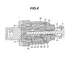
- Fig. 4 is a cross-sectional view illustrating a detailed structure of an electromagnetic valve in the plunger type high-pressure fuel pump relating to the embodiment.
- Fig. 5 is a cross-sectional view illustrating a configurational example in which a passage hole is provided in an anchor (which is configured with a valve member of the electromagnetic valve and is magnetically attracted by a core) to communicate between a hermetically closed space formed inside the electromagnetic valve and an external space formed outside of the hermetically closed space, in the plunger type high-pressure fuel pump according to the present embodiment.
- Fig. 6 is a cross-sectional view illustrating a configurational example in which the passage hole is provided in the core (which forms a magnetic circuit-forming body along with the body of the electromagnetic valve) to communicate between the hermetically closed space formed inside the electromagnetic valve and the external space formed outside of the hermetically closed space, in the plunger type high-pressure fuel pump according to the present embodiment.
- Fig. 7 illustrates another configurational example in which the passage hole is provided in the core (which forms the magnetic circuit-forming body along with the body of the electromagnetic valve) to communicate between the hermetically closed space formed inside the electromagnetic valve and the external space formed outside of the hermetically closed space, in the plunger type high-pressure fuel pump according to the present embodiment.
- Fig. 8 illustrates other configurational examples in which the passage hole is provided in each of the core and the anchor to communicate between the hermetically closed space formed inside the electromagnetic valve and the external space formed outside of the hermetically closed space, in the plunger type high-pressure fuel pump according to the present embodiment.
- the high-pressure fuel pump 1 is formed with a fuel suction passage 10, a fuel discharge passage 11, and a pressurizing chamber 12.
- a plunger 2, a pressurizing member, is slidably held by a cylinder portion 62 inside the high-pressure fuel pump 1.
- An end portion of the plunger 2 forms part of the pressurizing chamber 12.
- the plunger 2 is reciprocated by the rotation of a cam 100 to vary the volume of the pressurizing chamber 12.
- a suction valve 5 and a discharge valve 6 are installed in the fuel suction passage 10 and the fuel discharge passage 11, respectively.
- the suction valve 5 and the discharge valve 6 are held in one direction by springs 92 and 93, respectively, and each serve as a check valve for limiting the flow direction of fuel.
- An electromagnetic actuator 8 is held in the high-pressure fuel pump 1 and includes a solenoid coil 90, a rod (a valve member) 91, and the spring 92.
- the rod 91 receives a biasing force applied thereto by the spring 92 in the closing direction of the suction valve 5 with a drive signal not given to the electromagnetic actuator 8.
- the suction valve 5 is brought into a closed state as shown in Fig. 1 .
- Fuel is led by a low-pressure pump 51 from a tank 50 to a fuel introduction port 13 (see Fig. 2 ) of the high-pressure fuel pump 1 while the pressure of the fuel is regulated to a given pressure by a pressure regulator 52. Thereafter, the fuel is pressurized by the high-pressure fuel pump 1 and supplied under pressure from the fuel discharge passage 11 to a common rail 53. Injectors 54, a pressure sensor 56, and a safety valve 58 are attached to the common rail 53.
- the injectors 54 attached have the number made equal to that of cylinders of an engine and inject fuel in response to signals of a controller 57.
- the controller 57 includes an upper controller 63, a pump controller 59, and an injector controller 65.
- the pressure sensor 56 sends pressure data obtained to the upper controller 63.
- the upper controller 63 calculates an appropriate amount of injection fuel and fuel pressure, etc. on the basis of engine state amounts (a crank rotational angle, a throttle opening angle, engine speed, fuel pressure, etc.) obtained from various types of sensors.
- the upper controller 63 calculates timing to drive the high-pressure fuel pump 1 and the injectors 54 and a flow rate and sends drive signals thereto.
- the controller 57 is separately configured to include the upper controller 63 for calculating a command value; the pump controller 59 for directly sending a drive signal to the high-pressure fuel pump 1; and the injector controller 65 for sending drive signals to the injectors 54.
- the controller 57 may be configured to bring them into one unit.
- the plunger 2 is reciprocated by the cam 100 rotated by the engine camshaft or the like to increase and reduce the volume of the pressurizing chamber 12. If the plunger 2 is moved upward in Fig. 1 , the volume of the pressurizing chamber 12 is reduced. On the other hand, the plunger 2 is moved downward, the volume of the pressurizing chamber 12 is increased.
- the electromagnetic actuator 8 is operated (by de-energizing the solenoid coil 90) to close the suction valve 5
- the pressure in the pressurizing chamber 12 is increased to automatically open the discharge valve 6.
- fuel is supplied under pressure to the common rail 53.
- the suction valve 5 is automatically closed by the spring 92 even if the pressure of the pressurizing chamber 12 is lower than that of the fuel suction passage 10.
- the opening of the suction valve 5 is determined by the on-operation of the electromagnetic actuator 8.
- the plunger type high-pressure fuel pump is such that the closing timing of the electromagnetic valve thereof is controlled by the pump controller 59 to thereby control the volume of fuel discharged through the discharge valve. If the electromagnetic actuator 8 is given a drive signal by the pump controller 59, the solenoid coil 90 is energized to generate an electromagnetic field to thereby move the rod 91 rightward, in the example of the figure, against the biasing force of the spring 92. Then, if the plunger 2 is moved downward during the intake stroke, fuel is sucked from the suction passage 10 into the pressurizing chamber 12.
- the discharge valve 6 is set not to be opened by the pressure in the pressurizing chamber 12 (the so-called spill stroke is formed). In such a case, the discharge flow rate of the high-pressure fuel pump is zero.
- Fig. 2 depicts the structure of the plunger type high-pressure fuel pump according to the present embodiment.
- fuel is led from the fuel introduction port 13 via the fuel suction passage 10 to the pressurizing chamber 12 in which the fuel is increased in pressure and thus the pressurized fuel is supplied to the fuel discharge passage 11.
- the plunger 2 shown are the plunger 2, the plunger-biasing spring 4, the suction valve 5, the discharge valve 6, the electromagnetic valve 20, the rod (valve member) 91 of the suction valve 5, and an accumulator 21 (used to absorb low-pressure side pressure pulsations).
- Fig. 3 is a diagram for assistance in explaining pressure situations in the electromagnetic valve 20 and around the pressurizing chamber 12 in the plunger type high-pressure fuel pump.
- Fig. 3 illustrates the spill stroke described above, situations where the plunger 2 is moved upward to be increasing the fuel pressure in the pressurizing chamber 12 and a state where the solenoid coil 90 is just about to be de-energized to close the suction valve 5. Since the solenoid coil 90 is turned on in this situation, a right end of a left end side large-diameter portion of the rod (the valve member) 91 is abutted at a left end against a projecting portion 23 of the electromagnetic valve member so that a hermetically closed space 38 surrounded by such components is defined.
- the rod 91 when the solenoid coil 90 is energized, the rod 91 is moved rightward so that the large-diameter portion right end is abutted against the projecting portion 23 of the electromagnetic valve member 22. Thus, the rod 91 is positioned and stopped. In this stopped state, the hermetically closed space 38 is defined inside the electromagnetic valve.
- This pressure difference causes variations in the closing operation of the electromagnetic valve even if timing to turn off the drive current supplied to the solenoid coil is the same. For example, if the inside pressure of the hermetically closed space is low and the outside pressure of the external space is high, then the valve-closing timing will be accelerated. Specifically, the occurrence of the variations between the inside pressure and the outside pressure varies the valve-closing operation (the valve member operation varies even if the command of the valve-closing timing is issued at the same time). Consequently, the variations of the valve-closing operation affect the accurate control of the discharge amount of fuel.
- the object of the invention is to reduce the variations of the closing operation of the electromagnetic valve used in the plunger type high-pressure fuel pump.
- the major characteristic, i.e., the outline, of the present embodiment is that a fuel passage is provided to communicate between the hermetically closed space defined inside the electromagnetic valve and the external space formed outside of the hermetically closed space while the electromagnetic valve is opened, thereby preventing the occurrence of the internal-external pressure difference.
- Fig. 4 is a cross-sectional view illustrating the detailed structure of an electromagnetic valve in a plunger type high-pressure fuel pump relating to the embodiment of the present invention.
- Fig. 4 illustrates a basic configuration to which the characteristic structure of the embodiment is applied.
- Fig. 4 illustrates a basic configuration to which the characteristic structure of the embodiment is applied.
- the suction valve 5 shown are the suction valve 5, the fuel suction passage 10, the in-valve passage 15 (a fluid passage in the electromagnetic valve communicating with the suction passage 10 present in the high-pressure fuel pump 1), the solenoid coil 90, the rod (the valve member) 91, a core 30 (the electromagnetic valve member forming a magnetic circuit), a core projecting portion 31 (an electromagnetic valve member projecting portion), an anchor 32 (a magnetic body press fitted into the valve member 91 and magnetically attracted by the core 30), valve member guides 33, 34, a magnetic circuit-forming body 35, a frame 36 forming a magnetic path, a clearance 37, the hermetically closed space 38, and the external space 39.
- the suction valve 5 shown are the suction valve 5, the fuel suction passage 10, the in-valve passage 15 (a fluid passage in the electromagnetic valve communicating with the suction passage 10 present in the high-pressure fuel pump 1), the solenoid coil 90, the rod (the valve member) 91, a core 30 (the electromagnetic valve member forming a magnetic circuit
- the solenoid coil 90 is energized to allow the core 30, the frame 36, the magnetic circuit-forming body 35, and the anchor 32 to form the magnetic circuit.
- the anchor 32 is magnetically pulled by the core projecting portion 31 of the core 30 against the biasing force of the spring 92 to define the hermetically closed space 38 inside the electromagnetic valve.
- the right end side of the anchor 32 is brought into close contact with the left end side of the core projecting portion 31 to define the hermetically closed space 38.
- a clearance 37 is defined between the core projecting portion 31 and the rod (the valve member) 91 so as to enable smooth left-right movement of the rod 91.
- a clearance 45 is defined between the outer circumferential surface of the anchor 32 and the inner circumferential surface of the magnetic circuit-forming body 35.
- Figs. 5 through 8 illustrate the characteristics of the embodiments of the invention as configurational examples in which a fuel passage communicates between the inside and outside of the electromagnetic valve while the electromagnetic valve is opened.
- the provision of this communicating fuel passage can stabilize the closing timing of the electromagnetic valve.
- the configurational examples of Figs. 5 and 6 prevent the performance (attractive force) of the electromagnetic valve from lowering by providing the communicating fuel passage at a portion other than a magnetic attractive surface.
- the anchor 32 is internally and inclinedly formed with a passage hole 41 as a passage allowing the inside of the electromagnetic valve to communicate with the outside thereof while the electromagnetic valve is opened, that is, as a communicating passage between the hermetically closed space 38 and the external space 39.
- the passage hole 41 is inclined because the right end of the passage hole 41 is disposed to face the clearance 37 between the core projecting portion 31 and the valve member 91. Thus, the passage hole 41 communicates with the external space 39.
- the fuel passage in the configurational example of Fig. 5 is formed as the inclined passage hole 41.
- the fuel passage is not limited to this.
- the fuel passage may be a passage hole having any shape as long as the right end of the anchor 32 is disposed to face the clearance 37.
- an L-shaped passage hole may be applicable in which a hole is formed to extend from a position facing the clearance 45 between the magnetic circuit forming body 45 and the anchor 32 toward the valve member 91 and further extends along the inner circumferential side of the anchor 32.
- a passage hole 42 is inclinedly formed inside the core projecting portion 31 (a structure adapted to attract the right end of the anchor 32) of the core 30 (which forms the body of the electromagnetic valve and which is a magnetic path forming body), as a passage communicating between the hermetically closed space 38 and the external space 39 while the electromagnetic valve is opened.
- the hermetically closed space 38 is allowed to communicate with the external space 39 through the passage hole 42.
- the left end of the passage hole 42 is disposed to be offset from a position opposed to the right end portion of the anchor 32 (the passage hole 42 is disposed at a position other than a magnetic attractive surface). This prevents the core 30 from lowering the force of attracting the anchor 32.
- FIG. 7 depicts a passage-groove 43 provided at a portion of the magnetic attractive surface of the core projecting portion 31 included in the core 30.
- reference numeral 30 denotes a whole structure of the core
- 31 denotes the core projecting portion of the core
- 46 denotes a valve member insertion hole
- 49 denotes a core upper-lower lateral surface (see Fig. 6 ).
- the passage-groove 43 shown in Fig. 7 is the same as a passage groove 48 shown in Fig. 8(3) .
- the hermetically closed space 38 is allowed to communicate with the external space 39 through the passage-groove 43 formed at a portion of the magnetic attractive surface of the core.
- the passage-groove 43 causes the magnetic attractive force to slightly lower, the magnetic attractive surface needs only groove machining. Thus, fabrication can be facilitated.
- Fig. 8(2) illustrates a passage-groove 47 provided at a portion of the magnetic attractive surface of the anchor 32 by way of example.
- the function and operation of this configurational example are the same as those of Fig. 8(3).
- Fig. 8(1) illustrates a configurational example in which the core 30 and the anchor 32 are provided with passage-grooves 48 and 47, respectively.
- This makes the magnetic attractive force equal to that of the case where the passage-grooves are individually provided and aims to facilitate the fuel communication between the hermetically closed space 38 and the external space 39. In other words, this can eliminate a disadvantage that if fuel is hard to flow between the hermetically closed space and the external space, the valve member operates slowly.
Landscapes
- Engineering & Computer Science (AREA)
- Mechanical Engineering (AREA)
- General Engineering & Computer Science (AREA)
- Chemical & Material Sciences (AREA)
- Combustion & Propulsion (AREA)
- Fuel-Injection Apparatus (AREA)
- Magnetically Actuated Valves (AREA)
Claims (6)
- Hochdruckkraftstoffpumpe des Kolbentyps, die umfasst:einen Zylinder, der in der Pumpe (1) vorgesehen ist;einen Kolben (2), der in dem Zylinder gleitend vorgesehen ist und sich entsprechend einer Drehung eines Nockens hin und her bewegt;eine Fluiddruckbeaufschlagungskammer (12), die in der Pumpe vorgesehen ist, wobei sich ein Fassungsvermögen der Klammer durch die Hin- und Herbewegung des Kolbens ändert, und die zwischen dem Kolben (2) und dem Zylinder definiert ist;ein elektromagnetisches Ventil, das in einem zwischen der Druckbeaufschlagungskammer (12) und einem Fluidsaugdurchlass (10) definierten Raum vorgesehen ist; undein Förderventil (6), das in einem zwischen der Druckbeaufschlagungskammer und einem Fluidförderdurchlass definierten Raum vorgesehen ist;wobei das elektromagnetische Ventil enthält:ein Ventilelement (91), das ein Saugventil enthält, das eine Einlassseite der Druckbeaufschlagungskammer (12) öffnet und schließt;ein elastisches Element zum Vorbelasten des Ventilelements in eine Ventilschließrichtung;eine Solenoidspule (90), die dafür ausgelegt ist, das Ventilelement (91) in eine Öffnungsrichtung zu verlagern;einen Anker (32), der aus einem magnetischen Material hergestellt ist und durch eine elektromagnetische Kraft der zusammen mit dem Ventilelement (91) vorgesehenen Solenoidspule (90) betätigt wird; undeinen Kern (30), der einen Magnetkreis bildet, um den Anker (32) in Öffnungsrichtung durch die elektromagnetische Kraft anzuziehen und der den Innenraum des elektromagnetischen Ventils in einen hermetisch geschlossenen Raum (38) und in einen äußeren Raum (39), der mit dem Fluidsaugdurchlass kommuniziert, unterteilt,wobei der Anker (32) oder der Kern (30) mit einem Fluiddurchlass (41) versehen ist, durch den Fluid zwischen dem hermetisch geschlossenen Raum und dem äußeren Raum, die durch den Anker und den Kern gebildet sind, strömen kann, wenn das Saugventil (5) in einem geöffneten Zustand ist;dadurch gekennzeichnet, dass der Fluiddurchlass entweder eine radiale Fluiddurchlassnut (43, 47, 48) oder ein Fluiddurchlassloch (41, 42) ist, unddas Saugventil die Einlassseite der Fluiddruckbeaufschlagungskammer (12) direkt öffnet und schließt.
- Hochdruckkraftstoffpumpe des Kolbentyps nach Anspruch 1, wobei der Kern (30) in einem Mittelabschnitt mit einem Einsetzanschluss, der dafür ausgelegt ist, das darin eingesetzte Ventilelement (91) aufzunehmen, und an der Außenseite des Einsetzanschlusses mit einer Anschlagoberfläche, die an dem Anker anschlägt, versehen ist, wobei die Anschlagoberfläche mit einer radialen Fluiddurchlassnut (43, 48) ausgebildet ist.
- Hochdruckkraftstoffpumpe des Kolbentyps nach Anspruch 1 oder 2, wobei der Anker (32) eine Anschlagoberfläche besitzt, die an dem festen Kern (30) anschlägt, wobei die Anschlagoberfläche mit einer radialen Fluiddurchlassnut (47) ausgebildet ist und wobei Fluid in dem hermetisch geschlossenen Raum (38) mit dem äußeren Raum (39) über die Fluiddurchlassnut des Ankers (32) und über einen Zwischenraum (37) zwischen dem Kern (30) und dem Ventilelement (91) kommuniziert.
- Hochdruckkraftstoffpumpe des Kolbentyps nach wenigstens einem der vorhergehenden Ansprüche, wobei der Kern (30) in einem Mittelabschnitt mit einem Einsetzanschluss, der dafür ausgelegt ist, das darin eingesetzte Ventilelement (91) aufzunehmen, und an der Außenseite des Einsetzanschlusses mit einer Anschlagoberfläche, die an dem Anker (32) anschlägt, sowie an der Außenseite der Anschlagoberfläche mit einer Nichtanschlagoberfläche, die nicht an dem Anker (32) in Anschlag ist, versehen ist, und
der Kern (30) innen mit einem Fluiddurchlass (42) zwischen der Nichtanschlagoberfläche und einer mit dem äußeren Raum in Kontakt befindlichen Oberfläche ausgebildet ist. - Hochdruckkraftstoffpumpe des Kolbentyps nach wenigstens einem der vorhergehenden Ansprüche, wobei der Anker (32) eine Anschlagoberfläche besitzt, die sich gegenüber dem Kern, der durch das Ventilelement (91) eingesetzt ist, befindet und daran anschlägt, und der Anker (32) innen mit einem Fluiddurchlassloch (41) zwischen der Anschlagoberfläche des Ankers gegenüber einem Zwischenraum zwischen dem Kern (30) und dem Ventilelement (91) und einer Oberfläche des Ankers, die mit dem hermetisch geschlossenen Raum (38) in Kontakt ist, ausgebildet ist.
- Hochdruckkraftstoffpumpe des Kolbentyps nach wenigstens einem der vorhergehenden Ansprüche, wobei:der Kern (30) in einem Mittelabschnitt mit einem Einsetzanschluss versehen ist, der dafür ausgelegt ist, das darin eingesetzte Ventilelement (91) aufzunehmen, und an der Außenseite des Einsetzanschlusses mit einer Anschlagoberfläche in Anschlag an den Anker (32) versehen ist, wobei die Anschlagoberfläche mit einer Plattierungsoberfläche, die einer Plattierung unterworfen worden ist, versehen ist,
der Anker (32) eine Anschlagoberfläche in Anschlag an dem festen Kern besitzt, wobei die Anschlagoberfläche mit einer Plattierungsoberfläche, die einer Plattierung unterworfen worden ist, versehen ist, und
die plattierte Oberfläche des Kerns (30) und/oder die plattierte Oberfläche des Ankers (32) mit einer radialen Fluiddurchlassnut (43, 47, 48) versehen sind.
Applications Claiming Priority (1)
| Application Number | Priority Date | Filing Date | Title |
|---|---|---|---|
| JP2007280553A JP4701227B2 (ja) | 2007-10-29 | 2007-10-29 | プランジャ式高圧燃料ポンプ |
Publications (2)
| Publication Number | Publication Date |
|---|---|
| EP2055931A1 EP2055931A1 (de) | 2009-05-06 |
| EP2055931B1 true EP2055931B1 (de) | 2016-01-06 |
Family
ID=40263532
Family Applications (1)
| Application Number | Title | Priority Date | Filing Date |
|---|---|---|---|
| EP08018890.7A Active EP2055931B1 (de) | 2007-10-29 | 2008-10-29 | Hochdruckbrennstoffkolbenpumpe |
Country Status (4)
| Country | Link |
|---|---|
| US (2) | US20090120412A1 (de) |
| EP (1) | EP2055931B1 (de) |
| JP (1) | JP4701227B2 (de) |
| CN (1) | CN101424236B (de) |
Families Citing this family (17)
| Publication number | Priority date | Publication date | Assignee | Title |
|---|---|---|---|---|
| JP5331731B2 (ja) * | 2010-03-03 | 2013-10-30 | 日立オートモティブシステムズ株式会社 | 電磁式の流量制御弁及びそれを用いた高圧燃料供給ポンプ |
| US8677977B2 (en) * | 2010-04-30 | 2014-03-25 | Denso International America, Inc. | Direct injection pump control strategy for noise reduction |
| ITRM20110203A1 (it) * | 2011-04-21 | 2012-10-22 | Icomet Spa | Riduttore regolatore di pressione per l'alimentazione con metano od altri combustibili simili di motori a combustione interna |
| JP5537498B2 (ja) * | 2011-06-01 | 2014-07-02 | 日立オートモティブシステムズ株式会社 | 電磁吸入弁を備えた高圧燃料供給ポンプ |
| CN102562394A (zh) * | 2011-12-26 | 2012-07-11 | 联合汽车电子有限公司 | 电磁流量控制阀 |
| JP5677329B2 (ja) * | 2012-01-20 | 2015-02-25 | 日立オートモティブシステムズ株式会社 | 電磁駆動型の吸入弁を備えた高圧燃料供給ポンプ |
| US9562504B2 (en) | 2012-03-19 | 2017-02-07 | Hitachi, Ltd | Fuel pump for an internal combustion engine |
| JP5731562B2 (ja) * | 2012-07-04 | 2015-06-10 | 株式会社デンソー | 高圧ポンプ |
| DE102012212153A1 (de) * | 2012-07-11 | 2014-01-16 | Robert Bosch Gmbh | Hochdruckpumpe |
| JP6124728B2 (ja) * | 2013-08-07 | 2017-05-10 | 本田技研工業株式会社 | 燃料ポンプの制御装置 |
| EP3187725B1 (de) * | 2014-08-28 | 2019-06-05 | Hitachi Automotive Systems, Ltd. | Hochdruckbrennstoffförderpumpe |
| DE102015218284A1 (de) * | 2015-09-23 | 2017-03-23 | Robert Bosch Gmbh | Elektromagnetisch betätigbares Einlassventil und Hochdruckpumpe mit Einlassventil |
| US20170254306A1 (en) * | 2016-03-07 | 2017-09-07 | Stanadyne Llc | Inlet Control Valve With Snap-Off Coil Assembly |
| DE102017124485A1 (de) * | 2017-10-19 | 2019-04-25 | Eto Magnetic Gmbh | Elektromagnetische Aktuatorvorrichtung und Verwendung einer solchen |
| US10683825B1 (en) * | 2018-12-04 | 2020-06-16 | Delphi Technologies Ip Limited | Fuel pump and inlet valve assembly thereof |
| JP7349505B2 (ja) * | 2019-11-19 | 2023-09-22 | 日立Astemo株式会社 | 電磁弁機構及び高圧燃料供給ポンプ |
| US10947967B1 (en) | 2020-03-11 | 2021-03-16 | Halliburton Energy Services, Inc. | Discharge valve disabler and pressure pulse generator therefrom |
Family Cites Families (23)
| Publication number | Priority date | Publication date | Assignee | Title |
|---|---|---|---|---|
| DE2062420A1 (de) * | 1970-12-18 | 1972-06-22 | Bosch Gmbh Robert | Elektromagnetisch betätigbares Kraftstoff-Einspritzventil für eine Brennkraftmaschine |
| US4336781A (en) * | 1980-04-28 | 1982-06-29 | Stanadyne, Inc. | Fuel injection pump snubber |
| EP0083490A3 (de) * | 1981-12-31 | 1984-05-02 | Adwest Engineering Limited | Drehventil für eine hilfskraftverstärkte Lenkvorrichtung |
| JPS6032971A (ja) * | 1983-08-02 | 1985-02-20 | Nissan Motor Co Ltd | 内燃機関の燃料噴射装置 |
| JP3265598B2 (ja) * | 1991-11-21 | 2002-03-11 | 株式会社デンソー | 電磁弁 |
| JP3237549B2 (ja) * | 1996-11-25 | 2001-12-10 | トヨタ自動車株式会社 | 内燃機関の高圧燃料供給装置 |
| JP2000055229A (ja) * | 1998-08-07 | 2000-02-22 | Mitsubishi Electric Corp | 流体制御用電磁弁 |
| US6364430B1 (en) * | 1998-11-13 | 2002-04-02 | Mando Machinery Corporation | Solenoid valve for anti-lock brake system |
| JP3732723B2 (ja) * | 2000-07-06 | 2006-01-11 | 株式会社日立製作所 | 電磁式燃料噴射弁 |
| IT1316202B1 (it) * | 2000-09-08 | 2003-04-03 | Brahma S P A | Elettrovalvola per erogazione a portata variabile di un fluido. |
| DE10046040A1 (de) * | 2000-09-18 | 2002-04-04 | Bosch Gmbh Robert | Einrichtung zur Verbesserung der Reproduzierbarkeit der Einspritzdauer an Einspritzsystemen |
| CN1133810C (zh) * | 2001-02-16 | 2004-01-07 | 郗大光 | 电动燃油喷射装置 |
| JP2003120845A (ja) * | 2001-10-12 | 2003-04-23 | Denso Corp | 調量弁装置およびそれを用いた燃料噴射ポンプ |
| JP2005299683A (ja) * | 2001-11-27 | 2005-10-27 | Bosch Corp | 液体の流量制御弁および可動子のためのアンカー |
| JP2004137996A (ja) * | 2002-10-18 | 2004-05-13 | Denso Corp | 油圧制御弁 |
| JP2005511952A (ja) | 2002-11-27 | 2005-04-28 | 株式会社ボッシュオートモーティブシステム | 液体の流量制御弁および可動子のためのアンカー、ならびに燃料噴射システム |
| DE10255414B4 (de) * | 2002-11-28 | 2013-05-08 | Zf Friedrichshafen Ag | Proportional-Druckregelventil zur Regelung des Druckniveaus in einem Hydraulikkreis |
| DE10320592A1 (de) * | 2003-05-08 | 2004-11-25 | Robert Bosch Gmbh | Förderpumpe, insbesondere Hochdruck-Kraftstoffpumpe für eine Brennkraftmaschine |
| JP2006022727A (ja) * | 2004-07-08 | 2006-01-26 | Aisan Ind Co Ltd | 燃料噴射弁 |
| JP4415884B2 (ja) * | 2005-03-11 | 2010-02-17 | 株式会社日立製作所 | 電磁駆動機構,電磁弁機構及び電磁駆動機構によって操作される吸入弁を備えた高圧燃料供給ポンプ,電磁弁機構を備えた高圧燃料供給ポンプ |
| JP4561420B2 (ja) | 2005-03-17 | 2010-10-13 | 富士ゼロックス株式会社 | 画像形成装置及びその露光制御方法 |
| DE102005022661A1 (de) * | 2005-05-17 | 2007-02-15 | Robert Bosch Gmbh | Fluidpumpe, insbesondere Kraftstoff-Hochdruckpumpe für eine Brennkraftmaschine mit Kraftstoff-Direkteinspritzung |
| CN101506510B (zh) * | 2006-09-25 | 2012-07-11 | 株式会社日立制作所 | 燃料喷射阀 |
-
2007
- 2007-10-29 JP JP2007280553A patent/JP4701227B2/ja active Active
-
2008
- 2008-10-28 US US12/259,999 patent/US20090120412A1/en not_active Abandoned
- 2008-10-28 CN CN200810174606.1A patent/CN101424236B/zh active Active
- 2008-10-29 EP EP08018890.7A patent/EP2055931B1/de active Active
-
2013
- 2013-07-17 US US13/944,270 patent/US20130302192A1/en not_active Abandoned
Also Published As
| Publication number | Publication date |
|---|---|
| CN101424236B (zh) | 2012-01-04 |
| CN101424236A (zh) | 2009-05-06 |
| EP2055931A1 (de) | 2009-05-06 |
| US20090120412A1 (en) | 2009-05-14 |
| JP4701227B2 (ja) | 2011-06-15 |
| US20130302192A1 (en) | 2013-11-14 |
| JP2009108738A (ja) | 2009-05-21 |
Similar Documents
| Publication | Publication Date | Title |
|---|---|---|
| EP2055931B1 (de) | Hochdruckbrennstoffkolbenpumpe | |
| US9945373B2 (en) | Direct injection pump control strategy for noise reduction | |
| EP2317105B1 (de) | Hochdruck-Brennstoffförderpumpe und Brennstofffördersystem | |
| US8882475B2 (en) | Electromagnetic flow rate control valve and high-pressure fuel supply pump using the same | |
| EP2453122B1 (de) | Verfahren und Steuergerät zur Steuerung einer Hochdruckkraftstoffförderpumpe zur Speisung von Kraftstoff unter Druck in einen Verbrennungsmotor | |
| WO2012165555A1 (ja) | 電磁吸入弁を備えた高圧燃料供給ポンプ | |
| EP2063100A2 (de) | Kraftstoffdirekteinspritzpumpe für Verbrennungsmotoren | |
| US9657700B2 (en) | Inlet valve arrangement for a fuel pump | |
| US20150017039A1 (en) | High-pressure fuel supply pump having an electromagnetically-driven inlet valve | |
| US6672290B2 (en) | Internal combustion engine common-rail injection system with a fuel premetering device | |
| JP4478944B2 (ja) | 流体調量弁およびそれを用いた燃料噴射ポンプ | |
| JP6043865B2 (ja) | 高圧燃料供給ポンプ | |
| US6158419A (en) | Control valve assembly for pumps and injectors | |
| JP2003343384A (ja) | 高圧燃料供給装置 | |
| JPH08261019A (ja) | 燃料噴射ポンプの噴射時期制御装置 | |
| US6688291B2 (en) | High-pressure fuel supply system | |
| JPH11257191A (ja) | 可変吐出量高圧ポンプ | |
| WO2018016272A1 (ja) | 燃料供給ポンプ | |
| JP3794221B2 (ja) | 高圧燃料ポンプ | |
| JP2010163981A (ja) | 燃料噴射弁 | |
| JP2005207351A (ja) | 燃料噴射弁 | |
| JPH1162761A (ja) | 電磁弁 |
Legal Events
| Date | Code | Title | Description |
|---|---|---|---|
| PUAI | Public reference made under article 153(3) epc to a published international application that has entered the european phase |
Free format text: ORIGINAL CODE: 0009012 |
|
| AK | Designated contracting states |
Kind code of ref document: A1 Designated state(s): AT BE BG CH CY CZ DE DK EE ES FI FR GB GR HR HU IE IS IT LI LT LU LV MC MT NL NO PL PT RO SE SI SK TR |
|
| AX | Request for extension of the european patent |
Extension state: AL BA MK RS |
|
| 17P | Request for examination filed |
Effective date: 20090420 |
|
| 17Q | First examination report despatched |
Effective date: 20090709 |
|
| AKX | Designation fees paid |
Designated state(s): DE FR GB IT |
|
| GRAP | Despatch of communication of intention to grant a patent |
Free format text: ORIGINAL CODE: EPIDOSNIGR1 |
|
| INTG | Intention to grant announced |
Effective date: 20150703 |
|
| GRAS | Grant fee paid |
Free format text: ORIGINAL CODE: EPIDOSNIGR3 |
|
| GRAA | (expected) grant |
Free format text: ORIGINAL CODE: 0009210 |
|
| AK | Designated contracting states |
Kind code of ref document: B1 Designated state(s): DE FR GB IT |
|
| REG | Reference to a national code |
Ref country code: GB Ref legal event code: FG4D |
|
| REG | Reference to a national code |
Ref country code: DE Ref legal event code: R096 Ref document number: 602008041752 Country of ref document: DE |
|
| PG25 | Lapsed in a contracting state [announced via postgrant information from national office to epo] |
Ref country code: IT Free format text: LAPSE BECAUSE OF FAILURE TO SUBMIT A TRANSLATION OF THE DESCRIPTION OR TO PAY THE FEE WITHIN THE PRESCRIBED TIME-LIMIT Effective date: 20160106 |
|
| REG | Reference to a national code |
Ref country code: DE Ref legal event code: R097 Ref document number: 602008041752 Country of ref document: DE |
|
| PLBE | No opposition filed within time limit |
Free format text: ORIGINAL CODE: 0009261 |
|
| STAA | Information on the status of an ep patent application or granted ep patent |
Free format text: STATUS: NO OPPOSITION FILED WITHIN TIME LIMIT |
|
| 26N | No opposition filed |
Effective date: 20161007 |
|
| GBPC | Gb: european patent ceased through non-payment of renewal fee |
Effective date: 20161029 |
|
| REG | Reference to a national code |
Ref country code: FR Ref legal event code: ST Effective date: 20170630 |
|
| PG25 | Lapsed in a contracting state [announced via postgrant information from national office to epo] |
Ref country code: FR Free format text: LAPSE BECAUSE OF NON-PAYMENT OF DUE FEES Effective date: 20161102 Ref country code: GB Free format text: LAPSE BECAUSE OF NON-PAYMENT OF DUE FEES Effective date: 20161029 |
|
| REG | Reference to a national code |
Ref country code: DE Ref legal event code: R081 Ref document number: 602008041752 Country of ref document: DE Owner name: HITACHI ASTEMO, LTD., HITACHINAKA-SHI, JP Free format text: FORMER OWNER: HITACHI AUTOMOTIVE SYSTEMS, LTD., HITACHINAKA-SHI, IBARAKI, JP Ref country code: DE Ref legal event code: R081 Ref document number: 602008041752 Country of ref document: DE Owner name: HITACHI ASTEMO, LTD., HITACHINAKA-SHI, JP Free format text: FORMER OWNER: HITACHI, LTD., TOKYO, JP |
|
| PGFP | Annual fee paid to national office [announced via postgrant information from national office to epo] |
Ref country code: DE Payment date: 20230906 Year of fee payment: 16 |