EP2048263B1 - Werkstückträgereinrichtung - Google Patents
Werkstückträgereinrichtung Download PDFInfo
- Publication number
- EP2048263B1 EP2048263B1 EP07405302A EP07405302A EP2048263B1 EP 2048263 B1 EP2048263 B1 EP 2048263B1 EP 07405302 A EP07405302 A EP 07405302A EP 07405302 A EP07405302 A EP 07405302A EP 2048263 B1 EP2048263 B1 EP 2048263B1
- Authority
- EP
- European Patent Office
- Prior art keywords
- workpiece
- toothing
- workpiece carrier
- driving
- carrier device
- Prior art date
- Legal status (The legal status is an assumption and is not a legal conclusion. Google has not performed a legal analysis and makes no representation as to the accuracy of the status listed.)
- Not-in-force
Links
Images


Classifications
-
- B—PERFORMING OPERATIONS; TRANSPORTING
- B23—MACHINE TOOLS; METAL-WORKING NOT OTHERWISE PROVIDED FOR
- B23Q—DETAILS, COMPONENTS, OR ACCESSORIES FOR MACHINE TOOLS, e.g. ARRANGEMENTS FOR COPYING OR CONTROLLING; MACHINE TOOLS IN GENERAL CHARACTERISED BY THE CONSTRUCTION OF PARTICULAR DETAILS OR COMPONENTS; COMBINATIONS OR ASSOCIATIONS OF METAL-WORKING MACHINES, NOT DIRECTED TO A PARTICULAR RESULT
- B23Q1/00—Members which are comprised in the general build-up of a form of machine, particularly relatively large fixed members
- B23Q1/25—Movable or adjustable work or tool supports
- B23Q1/64—Movable or adjustable work or tool supports characterised by the purpose of the movement
-
- C—CHEMISTRY; METALLURGY
- C23—COATING METALLIC MATERIAL; COATING MATERIAL WITH METALLIC MATERIAL; CHEMICAL SURFACE TREATMENT; DIFFUSION TREATMENT OF METALLIC MATERIAL; COATING BY VACUUM EVAPORATION, BY SPUTTERING, BY ION IMPLANTATION OR BY CHEMICAL VAPOUR DEPOSITION, IN GENERAL; INHIBITING CORROSION OF METALLIC MATERIAL OR INCRUSTATION IN GENERAL
- C23C—COATING METALLIC MATERIAL; COATING MATERIAL WITH METALLIC MATERIAL; SURFACE TREATMENT OF METALLIC MATERIAL BY DIFFUSION INTO THE SURFACE, BY CHEMICAL CONVERSION OR SUBSTITUTION; COATING BY VACUUM EVAPORATION, BY SPUTTERING, BY ION IMPLANTATION OR BY CHEMICAL VAPOUR DEPOSITION, IN GENERAL
- C23C14/00—Coating by vacuum evaporation, by sputtering or by ion implantation of the coating forming material
- C23C14/22—Coating by vacuum evaporation, by sputtering or by ion implantation of the coating forming material characterised by the process of coating
- C23C14/50—Substrate holders
- C23C14/505—Substrate holders for rotation of the substrates
-
- C—CHEMISTRY; METALLURGY
- C23—COATING METALLIC MATERIAL; COATING MATERIAL WITH METALLIC MATERIAL; CHEMICAL SURFACE TREATMENT; DIFFUSION TREATMENT OF METALLIC MATERIAL; COATING BY VACUUM EVAPORATION, BY SPUTTERING, BY ION IMPLANTATION OR BY CHEMICAL VAPOUR DEPOSITION, IN GENERAL; INHIBITING CORROSION OF METALLIC MATERIAL OR INCRUSTATION IN GENERAL
- C23C—COATING METALLIC MATERIAL; COATING MATERIAL WITH METALLIC MATERIAL; SURFACE TREATMENT OF METALLIC MATERIAL BY DIFFUSION INTO THE SURFACE, BY CHEMICAL CONVERSION OR SUBSTITUTION; COATING BY VACUUM EVAPORATION, BY SPUTTERING, BY ION IMPLANTATION OR BY CHEMICAL VAPOUR DEPOSITION, IN GENERAL
- C23C16/00—Chemical coating by decomposition of gaseous compounds, without leaving reaction products of surface material in the coating, i.e. chemical vapour deposition [CVD] processes
- C23C16/44—Chemical coating by decomposition of gaseous compounds, without leaving reaction products of surface material in the coating, i.e. chemical vapour deposition [CVD] processes characterised by the method of coating
- C23C16/458—Chemical coating by decomposition of gaseous compounds, without leaving reaction products of surface material in the coating, i.e. chemical vapour deposition [CVD] processes characterised by the method of coating characterised by the method used for supporting substrates in the reaction chamber
-
- F—MECHANICAL ENGINEERING; LIGHTING; HEATING; WEAPONS; BLASTING
- F16—ENGINEERING ELEMENTS AND UNITS; GENERAL MEASURES FOR PRODUCING AND MAINTAINING EFFECTIVE FUNCTIONING OF MACHINES OR INSTALLATIONS; THERMAL INSULATION IN GENERAL
- F16H—GEARING
- F16H21/00—Gearings comprising primarily only links or levers, with or without slides
- F16H21/10—Gearings comprising primarily only links or levers, with or without slides all movement being in, or parallel to, a single plane
- F16H21/12—Gearings comprising primarily only links or levers, with or without slides all movement being in, or parallel to, a single plane for conveying rotary motion
- F16H21/14—Gearings comprising primarily only links or levers, with or without slides all movement being in, or parallel to, a single plane for conveying rotary motion by means of cranks, eccentrics, or like members fixed to one rotary member and guided along tracks on the other
-
- H—ELECTRICITY
- H10—SEMICONDUCTOR DEVICES; ELECTRIC SOLID-STATE DEVICES NOT OTHERWISE PROVIDED FOR
- H10P—GENERIC PROCESSES OR APPARATUS FOR THE MANUFACTURE OR TREATMENT OF DEVICES COVERED BY CLASS H10
- H10P72/00—Handling or holding of wafers, substrates or devices during manufacture or treatment thereof
- H10P72/30—Handling or holding of wafers, substrates or devices during manufacture or treatment thereof for conveying, e.g. between different workstations
- H10P72/32—Handling or holding of wafers, substrates or devices during manufacture or treatment thereof for conveying, e.g. between different workstations between different workstations
- H10P72/3212—Handling or holding of wafers, substrates or devices during manufacture or treatment thereof for conveying, e.g. between different workstations between different workstations the substrates to be conveyed not being semiconductor wafers or large planar substrates, e.g. chips or lead frames
Definitions
- the invention relates to a workpiece support device according to the preamble of claim 1.
- Such devices are used for machining workpieces, especially in vacuum systems, in particular for coating the same.
- a generic workpiece carrier device in which the transmitter part is formed as an eccentrically connected to a rotation axis drive pulley, which is surrounded by a corresponding recess on the transmission part just.
- An influence on the translation ratio between the rotation of the workpieces and that of the bogie is possible only via a countershaft transmission, which directly controls the movement of the drive pulley.
- Another workpiece carrier device is off EP 1 153 155 A1 known.
- the rotatably mounted on bogies workpiece holder are rotated by a respective gear on the workpiece holder engages with a drive axis of the bogie coaxially surrounding ring gear, which is the base frame against rotation.
- This known workpiece carrier device is constructed relatively complex. The translation ratio can only be selected within fairly narrow limits.
- the rotation of the workpiece holder is effected by anchored to the base carrier, which intervene with them temporarily.
- the rotation is intermittent, which is generally disadvantageous in itself and, especially if a coating of several very thin layers is applied, can affect the quality of the workpieces.
- DE 103 08 471 A1 shows a workpiece carrier device, in which workpiece carriers are arranged in a plurality of concentric rings on a bogie. By engaging with a stationary central gear intermediate gear on the bogie each workpiece carrier of a ring is rotated. The workpiece carriers belonging to a ring are operatively connected to one another in such a way that this rotation is transferred to the remaining workpiece carriers.
- the invention is based on the object to provide a generic workpiece support device, which is simple in construction and reliable and offers the possibility to easily adjust the translation ratio. This object is solved by the features in the characterizing part of claim 1.
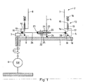
- a workpiece carrier device on a fixed base frame 1, a workpiece carrier 2 arranged with a bogie 3, which is rotatably supported about a vertical drive shaft 4 on the base frame 1 and at the lower end on its outer side carries a ring gear 5, with which a driven by a motor 6 gear 7 engages
- the bogie 3 is formed as approximately closed to the drive axis 4 rotationally symmetrical closed housing with central tube sections 8, between which along the drive axis 4 successive projections are (in Fig. 1 only the lowest is shown, s. also Fig. 4 ), which are each formed by a bottom 9, a cover 10 and an outer ring 11 concentric with the pipe sections 8, which adjoins the outer edge of the bottom 9 and projects slightly beyond the outer edge of the cover 10.
- the bogie 3 carries at each of said projections a group 12 of workpiece holders 13, which are distributed uniformly at the same height in each case over a circle surrounding the drive axle 4.
- Each workpiece holder 13 is rotatable about a holder axis parallel to the drive axis 4 and comprises a base 14 which lies partly within a projection of the bogie 3 and a holder 15 for fixing a workpiece 16, which is connected to the base 14 via an axis pin 17 performed by the cover 10.
- the base 14 comprises a bearing pin 18 with a downwardly pointing conical tip whose axis coincides with the axis of the axle 17 as with the axle and in the bottom 9, where the tip engages in a corresponding recess, is rotatably mounted.
- the bearing pin 18 and the axle pin 17 are each connected by a crank-like intermediate portion, which comprises a parallel to the holder axis, but spaced from her drive pin 19.
- the base 14 is a simple bent part of substantially constant cross-section.
- the plugged holder 15 has an open-topped cylindrical recess into which the workpiece 16, such as a milling head, is inserted.
- a rotatably anchored to the base frame 1 shaft 20 carries at the height of each of the groups 12 with respect to the base frame 1 non-rotatable central wheel 21 (see also Fig. 2, 3rd ) with an external toothing.
- a drive part 22 is arranged, which comprises a rotatable about the drive shaft 4 bracket with a lying above the central wheel 21 upper arm 23 and a similar underlying below the central wheel 21 lower arm 24 and attached to the bracket intermediate gear, the in the example only consists of a pinion 25 mounted between the upper arm 23 and the lower arm 24, which is rotatable about a pinion axis parallel to the drive axis 4 and whose toothing engages with that of the central wheel 21.
- the pinion 25 is connected to the drive pins 19 of the lying at the height of the central wheel 21 and the drive member 22 group 12 of workpiece carriers 13 by apianebertragerteil 26 having a circular central coupling recess. Its edge carries an inwardly facing sprocket 27 which engages with the toothing of the pinion 25.
- the transmitter part 26 for each workpiece holder 13 has a drive opening 28, through which the drive pin 19, surrounded by its edge just protrudes.
- the transmission part 26 is thus rotatable with the workpiece holders 13, but otherwise connected with little play and is in contact with the drive part 22, more precisely the pinion 25 thereof.
- the center of the ring gear 27 on the transmission part 26 forms a drive point 29, which is spaced from the drive axle 4 by an eccentricity E.
- the distance of the drive pin 19 of each workpiece holder 13 from the respective holder axis also corresponds to the eccentricity E.
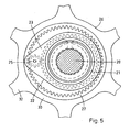
- the transfer part 26, which is in Fig. 2, 3rd is shown only schematically, can (s. Fig. 4 where a projection is shown, but while parts of the housing, most of the workpiece carrier 13 and the shaft 20 are omitted) may be formed as a flat stamped part with an inner ring 30 which surrounds said coupling recess and an outer ring 31, in which in this case Sixty-six drive openings 29 are mounted for engagement with as many workpiece carriers 13 distributed over the circumference.
- the inner ring 30 and the outer ring 31 are connected by radial spokes 32 which, in the example, are weakened by holes 33, so that they have predetermined breaking points form, which break in the case of a blockage of the workpiece holder 13 of the corresponding group 12.
- the transmission ratio depends only on z and can be easily changed, for example, by replacing the shaft 20 with the central wheels 21 and the drive parts 22.
- another shaft with smaller central wheels can be used and thus reduced z and the transmission ratio u can be increased correspondingly (2).
- the engagement with the sprocket of the transmission part then requires larger Pinion, but which do not affect the translation ratio u . If necessary, the transmission parts can also be replaced, but this is more complicated.
- gear ratio u can also be set differently for different groups of workpiece carriers by using a shaft with different intermediate gears and / or central gears.
- the central teeth need not be rotatably connected to the base frame. It is for example possible to connect the shaft carrying the central wheels via a driven by the movement of the bogie countershaft transmission with the base frame, so that the central toothing each performs a rotational movement.
- a countershaft transmission can be approximately as in WO 2007/025 397 A1 be executed described and installed. Also in this case, the gear ratio can be easily changed by replacing the shaft with the center gears and driving parts as described above.
Landscapes
- Chemical & Material Sciences (AREA)
- Engineering & Computer Science (AREA)
- Mechanical Engineering (AREA)
- General Engineering & Computer Science (AREA)
- Chemical Kinetics & Catalysis (AREA)
- Metallurgy (AREA)
- Organic Chemistry (AREA)
- Materials Engineering (AREA)
- General Chemical & Material Sciences (AREA)
- Retarders (AREA)
- Gear Transmission (AREA)
- Grinding Of Cylindrical And Plane Surfaces (AREA)
- Electrical Discharge Machining, Electrochemical Machining, And Combined Machining (AREA)
- Physical Vapour Deposition (AREA)
- Specific Conveyance Elements (AREA)
- Mechanical Treatment Of Semiconductor (AREA)
- Agricultural Machines (AREA)
- Soil Working Implements (AREA)
- Finish Polishing, Edge Sharpening, And Grinding By Specific Grinding Devices (AREA)
Description
- Die Erfindung betrifft eine Werkstückträgereinrichtung gemäss dem Oberbegriff des Anspruchs 1. Derartige Einrichtungen werden zur Bearbeitung von Werkstücken vor allem in Vakuumanlagen, insbesondere zur Beschichtung derselben verwendet.
- Aus
WO 2007/025 397 A1 ist eine gattungsgemässe Werkstückträgereinrichtung bekannt, bei der das Uebertragerteil als exzentrisch mit einer Drehachse verbundene Antriebsscheibe ausgebildet ist, welche von einer entsprechenden Ausnehmung am Uebertragerteil knapp umgeben ist. Eine Beeinflussung des Uebersetzungsverhältnisses zwischen der Drehung der Werkstücke und der des Drehgestells ist nur über ein Vorgelegegetriebe möglich, das direkt die Bewegung der Antriebsscheibe steuert. - Eine weitere Werkstückträgereinrichtung ist aus
EP 1 153 155 A1 bekannt. Hier werden die an Drehgestellen drehbar gelagerten Werkstückhalter gedreht, indem jeweils ein Zahnrad am Werkstückhalter mit einem die Antriebsachse des Drehgestells koaxial umgebenden Zahnkranz eingreift, der dem Grundgestell gegenüber unverdrehbar ist. Diese bekannte Werkstückträgereinrichtung ist verhältnismässig komplex aufgebaut. Das Uebersetzungsverhältnis ist nur innerhalb ziemlich enger Grenzen wählbar. - Bei einer der aus der
DE 198 03 278 A1 ersichtlichen Werkstückträgereinrichtungen wird die Drehung der Werkstückhalter durch am Grundgestell verankerte Mitnehmer bewirkt, die mit denselben vorübergehend eingreifen. In diesem Fall ist die Drehung intermittierend, was an sich meist nachteilig ist und, vor allem wenn eine Beschichtung aus mehreren sehr dünnen Lagen angelegt wird, die Qualität der Werkstücke beeinträchtigen kann. -
DE 103 08 471 A1 zeigt eine Werkstückträgereinrichtung, bei welcher Werkstückträger in mehreren konzentrischen Ringen auf einem Drehgestell angeordnet sind. Durch ein mit einem stillstehenden Zentralrad eingreifendes Zwischengetriebe auf dem Drehgestell wird jeweils ein Werkstückträger eines Ringes in Drehung versetzt. Die zu einem Ring gehörigen Werkstückträger sind so miteinander wirkverbunden, dass sich diese Drehung auf die übrigen Werkstückträger überträgt. - Der Erfindung liegt die Aufgabe zu Grunde, eine gattungsgemässe Werkstückträgereinrichtung anzugeben, die einfach im Aufbau und zuverlässig ist und die Möglichkeit bietet, auf einfache Weise das Uebersetzungsverhältnis einzustellen. Diese Aufgabe wird durch die Merkmale im Kennzeichen des Anspruchs 1 gelöst.
- Die durch die Erfindung erzielten Vorteile liegen vor allem darin, dass der Antrieb der Werkstückhalter sehr einfach ist und dennoch eine Wahl des Uebersetzungsverhältnisses aus einem verhältnismässig weiten Bereich zulässt.
- Im folgenden wird die Erfindung anhand von Figuren, welche lediglich Ausführungsbeispiele darstellen, näher erläutert. Es zeigen
- Fig. 1
- schematisch einen axialen Schnitt durch eine erfindungsgemässe Werkstückträgereinrichtung gemäss einer ersten Ausführungsform,
- Fig. 2
- einen Ausschnitt aus
Fig. 1 , - Fig. 3
- eine Draufsicht auf den Ausschnitt gemäss
Fig. 2 , - Fig. 4
- teilweise geschnitten einen Teil der erfindungsgemässen Werkstückträgereinrichtung in perspektivischer Darstellung und
- Fig. 5
- vergrössert eine Draufsicht auf einen Teil der erfindungsgemässen Werkstückträgereinrichtung.
- Gemäss einer bevorzugten Ausführungsform einer erfindungsgemässen Werkstückträgereinrichtung ist (
Fig. 1 ) auf einem feststehenden Grundgestell 1 ein Werkstückträger 2 angeordnet mit einem Drehgestell 3, das um eine senkrechte Antriebsachse 4 drehbar am Grundgestell 1 gelagert ist und am unteren Ende an seiner Aussenseite einen Zahnkranz 5 trägt, mit welchem ein von einem Motor 6 angetriebenes Zahnrad 7 eingreift. Das Drehgestell 3 ist als um die Antriebsachse 4 annähernd rotationssymmetrisches geschlossenes Gehäuse ausgebildet mit zentralen Rohrabschnitten 8, zwischen denen längs der Antriebsachse 4 aufeinanderfolgende Auskragungen liegen (inFig. 1 ist nur die unterste dargestellt, s. auchFig. 4 ), welche jeweils von einem Boden 9, einem Deckel 10 und einem zu den Rohrabschnitten 8 konzentrischen Aussenring 11 gebildet werden, der an den Aussenrand des Bodens 9 anschliesst und den Aussenrand des Deckels 10 etwas überragt. - Das Drehgestell 3 trägt an jeder der besagten Auskragungen eine Gruppe 12 von Werkstückhaltern 13, die jeweils auf gleicher Höhe gleichmässig über einen die Antriebsachse 4 umgebenden Kreis verteilt sind. Jeder Werkstückhalter 13 ist um eine zur Antriebsachse 4 parallele Halterachse drehbar und umfasst eine Basis 14, die z.T. innerhalb einer Auskragung des Drehgestells 3 liegt und eine Halterung 15 zur Befestigung eines Werkstücks 16, welche mit der Basis 14 über einen durch den Deckel 10 durchgeführten Achsstift 17 verbunden ist. Weiter umfasst die Basis 14 einen Lagerstift 18 mit einer nach unten weisenden kegelförmigen Spitze, dessen Achse wie beim Achsstift 17 mit der Halterachse zusammenfällt und im Boden 9, wo die Spitze in eine entsprechende Ausnehmung eingreift, drehbar gelagert ist. Der Lagerstift 18 und der Achsstift 17 sind jeweils durch einen kurbelartigen Zwischenabschnitt verbunden, welcher einen zur Halterachse parallelen, aber von ihr beabstandeten Antriebsstift 19 umfasst. Die Basis 14 ist ein einfaches Biegeteil von im wesentlichen gleichbleibendem Querschnitt. Die aufgesteckte Halterung 15 weist eine oben offene zylindrische Ausnehmung auf, in welche das Werkstück 16, z.B. ein Fräskopf, eingesteckt ist.
- Eine am Grundgestell 1 drehfest verankerte Welle 20 trägt auf der Höhe jeder der Gruppen 12 ein gegenüber dem Grundgestell 1 unverdrehbares Zentralrad 21 (s. a.
Fig. 2, 3 ) mit einer Aussenverzahnung. Jeweils auf gleicher Höhe ist ein Antriebsteil 22 angeordnet, welches eine um die Antriebsachse 4 drehbare Halterung mit einem oberhalb des Zentralrades 21 liegenden oberen Arm 23 und einem gleichartigen unterhalb des Zentralrades 21 liegenden unteren Arm 24 umfasst sowie ein an an der Halterung angebrachtes Zwischengetriebe, das im Beispiel lediglich aus einem zwischen dem oberen Arm 23 und dem unteren Arm 24 gelagerten Ritzel 25 besteht, das um eine zur Antriebsachse 4 parallele Ritzelachse drehbar ist und dessen Verzahnung mit der des Zentralrades 21 eingreift. - Das Ritzel 25 ist mit den Antriebsstiften 19 der auf der Höhe des Zentralrades 21 und des Antriebsteils 22 liegenden Gruppe 12 von Werkstückträgern 13 durch ein Uebertragerteil 26 verbunden, das eine kreisförmige zentrale Kopplungsausnehmung aufweist. Ihr Rand trägt einen nach innen weisenden Zahnkranz 27, welcher mit der Verzahnung des Ritzels 25 eingreift. Weiter aussen weist das Uebertragerteil 26 für jeden Werkstückhalter 13 eine Antriebsöffnung 28 auf, durch welche dessen Antriebsstift 19, von ihrem Rand knapp umgeben, ragt. Das Uebertragerteil 26 ist also mit den Werkstückhaltern 13 jeweils drehbar, aber im übrigen mit geringem Spiel verbunden und steht mit dem Antriebsteil 22, genauer dem Ritzel 25 desselben, im Eingriff.
- Der Mittelpunkt des Zahnkranzes 27 am Uebertragerteil 26 bildet einen Abtriebspunkt 29, der von der Antriebsachse 4 um eine Exzentrizität E beabstandet ist. Der Abstand des Antriebsstiftes 19 eines jeden Werkstückhalters 13 von der jeweiligen Halterachse entspricht ebenfalls der Exzentrizität E.
- Das Uebertragerteil 26, das in
Fig. 2, 3 nur schematisch dargestellt ist, kann (s.Fig. 4 , wo eine Auskragung dargestellt ist, aber dabei Teile des Gehäuses, die meisten Werkstückträger 13 und die Welle 20 weggelassen sind) als ebenes Stanzteil ausgebildet sein mit einem Innenring 30, der die besagte Kopplungsausnehmung umgibt und einem Aussenring 31, in dem die in diesem Fall sechsundsechzig Antriebsöffnungen 29 für den Eingriff mit ebensovielen Werkstückträgern 13 über den Umfang verteilt angebracht sind. Der Innenring 30 und der Aussenring 31 sind durch radiale Speichen 32 verbunden, welche, im Beispiel durch Löcher 33, geschwächt sind, sodass sie Sollbruchstellen bilden, die im Fall einer Blockierung eines der Werkstückhalter 13 der entsprechenden Gruppe 12 brechen. - Wird das Drehgestell 3 durch den Motor 6 um die Antriebsachse 4 gedreht, so wird über die mit dem Drehgestell 3 verbundenen Werkstückträger 13 das mit denselben eingreifende Uebertragerteil 26 mitgenommen. Da die Verzahnung des Ritzels 25 mit dem Zahnkranz 27 eingreift, wird dasselbe auch in Drehung versetzt und läuft auf dem Zentralrad 21 ab, wodurch das Antriebsteil 22 gegenüber dem Uebertragerteil 26 verdreht wird und eine Exzenterbewegung desselben bewirkt, bei welcher der die Drehachse 4 mit dem Abtriebspunkt 29 verbindende Vektor, dessen Länge der Exzentrizität E entspricht, um die Drehachse 4 umläuft. Die Exzenterbewegung überträgt sich auf die Antriebsstifte 19, sodass jeder Umlauf der Exzenterbewegung eine Umdrehung der Werkstückträger 13 bewirkt, wobei jeweils der von der Halterachse zum entsprechenden Antriebsstift 19 weisende Vektor jederzeit zum obengenannten Vektor parallel ist.
- Betrachtet man die Bewegungen des Uebertragerteils 26 und des Antriebsteils 22 in einem am Grundgestell 1 festgemachten Koordinatensystem (s. dazu
Fig. 3 ,5 , in letzterer ist der Deckel 10 weggelassen) und bezeichnet man die Zahnzahl der Zentral verzahnung, d.h. der Verzahnung des Zentralrades 21 mit ZZ und diejenige der Uebertragerverzahnung, d.h. der Verzahnung des Zahnkranzes 27 mit ZU , so ergibt sich bei einer Umdrehung des Antriebsteils 22 um die Antriebsachse 4 im Uhrzeigersinn, entsprechend einem Umlauf bei der Exzenterbewegung des Uebertragerteils 26, d.h. UU =1, eine Drehung UD desselben und damit des Drehgestells 3 von
- Umdrehungen im Uhrzeigersinn. Mit z=ZZ /ZU gilt also

- Dies ergibt sich daraus, dass das Uebertragerteil 26 einerseits mitdreht, d.h. ebenfalls eine volle Umdrehung im Uhrzeigersinn ausführt und andererseits zusätzlich durch das auf dem Zentralrad 21 ablaufende Ritzel 25 um z Umdrehungen gedreht wird. Auf 1+z Umdrehungen des Drehgestells 3 kommt also eine Umdrehung des Antriebsteils 22. Damit ergibt sich für das Uebersetzungsverhältnis, d.h. den Quotienten zwischen der Drehrate des Antriebsteils 22 und damit der Exzenterbewegung des Uebertragerteils 26 einerseits und der Drehrate des Drehgestells 3 andererseits

- Gilt also z.B. wie beim Ausführungsbeispiel gemäss
Fig. 4 ,5 ZZ =46 und ZU =60, so ergibt sich z zu ca. 0,77 und u zu ca. 0,57. Gegenüber dem Drehgestell 3 läuft die Exzenterbewegung rückwärts. Das Verhältnis der Drehraten beträgt u-1, also im Beispiel ca. -0,43. - Das Uebersetzungsverhältnis hängt nur von z ab und kann z.B. durch Auswechseln der Welle 20 mit den Zentralrädern 21 und den Antriebsteilen 22 leicht geändert werden. So kann etwa eine andere Welle mit kleineren Zentralrädern eingesetzt und damit z verkleinert und das Uebersetzungsverhältnis u entsprechend (2) vergrössert werden. Der Eingriff mit dem Zahnkranz des Uebertragerteils verlangt dann grössere Ritzel, welche aber das Uebersetzungsverhältnis u nicht beeinflussen. Falls nötig können zusätzlich die Uebertragerteile ausgewechselt werden, doch ist dies aufwendiger.
- Es ist jedoch leicht möglich, statt eines Ritzels ein komplexeres Zwischengetriebe mit mehreren an der Halterung des Antriebsteils gelagerten, miteinander in Wirkverbindung stehenden Zahnrädern, von denen eines mit der Zentralverzahnung und eines mit der Uebertragerverzahnung eingreift, einzusetzen. Das Uebersetzungsverhältnis u kann für verschiedene Gruppen von Werkstückträgern auch unterschiedlich eingestellt werden, indem eine Welle mit unterschiedlichen Zwischengetrieben und/oder Zentralrädern verwendet wird.
- Die Ausbildung des geschilderten Ausführungsbeispiels kann auch in anderer Weise abgewandelt werden, ohne dass das Gebiet der Erfindung verlassen würde. So braucht die Zentralverzahnung nicht drehfest mit dem Grundgestell verbunden sein. Es ist z.B. möglich, die die Zentralräder tragende Welle über ein von der Bewegung des Drehgestells angetriebenes Vorgelegegetriebe mit dem Grundgestell zu verbinden, sodass die Zentralverzahnung jeweils eine Drehbewegung ausführt. Ein solches Vorgelegegetriebe kann etwa wie in
WO 2007/025 397 A1 beschrieben ausgeführt und eingebaut sein. Auch in diesem Fall kann das Uebersetzungsverhältnis leicht durch Auswechseln der Welle mit den Zentralrädern und Antriebsteilen wie oben beschrieben geändert werden. Eine Ausführung, wie sie in der genannten Schrift in Fig. 10 dargestellt ist, bei der mehrere dem im Zusammenhang mit dem Ausführungsbeispiel beschriebenen entsprechende Werkstückträger um eine Hauptachse herum angeordnet sind, um die das Grundgestell durch einen Motor drehbar ist, während die Zahnkränze ihrer Drehgestelle mit einem ortsfesten Zahnrad eingreifen, ist ebenfalls möglich. -
- 1
- Grundgestell
- 2
- Werkstückträger
- 3
- Drehgestell
- 4
- Antriebsachse
- 5
- Zahnkranz
- 6
- Motor
- 7
- Zahnrad
- 8
- Rohrabschnitt
- 9
- Boden
- 10
- Deckel
- 11
- Aussenring
- 12
- Gruppe
- 13
- Werkstückhalter
- 14
- Basis
- 15
- Halterung
- 16
- Werkstück
- 17
- Achsstift
- 18
- Lagerstift
- 19
- Antriebsstift
- 20
- Welle
- 21
- Zentralrad
- 22
- Antriebsteil
- 23
- oberer Arm
- 24
- unterer Arm
- 25
- Ritzel
- 26
- Uebertragerteil
- 27
- Zahnkranz
- 28
- Antriebsöffnung
- 29
- Abtriebspunkt
- 30
- Innenring
- 31
- Aussenring
- 32
- Speiche
- 33
- Loch
Claims (10)
- Werkstückträgereinrichtung mit mindestens einem Werkstückträger (2), welcher ein um eine Antriebsachse (4) drehbar an einem Grundgestell (1) gelagertes Drehgestell (3) und ein ebenfalls um die Antriebsachse (4) dem Drehgestell (3) gegenüber drehbares Antriebsteil (22) sowie mehrere von der Antriebsachse (4) beabstandete und um zu derselben parallele Halterachsen drehbar am Drehgestell (3) gelagerte Werkstückhalter (13) umfasst, sowie mit mindestens einem starren Uebertragerteil (26) zur Drehung der Werkstückhalter (13) gegenüber dem Drehgestell (3), das einerseits mit dem Antriebsteil (22) um einen von der Antriebsachse (4) um eine Exzentrizität (E) beabstandeten Abtriebspunkt (29) und andererseits mit mindestens zwei Werkstückhaltern (13) jeweils um einen um eine gleiche Exzentrizität (E) von der Halterachse beabstandeten Antriebspunkt drehbar eingreift, dadurch gekennzeichnet, dass sie eine am Grundgestell (1) gelagerte, die Antriebsachse (4) umgebende Zentralverzahnung umfasst und das Uebertragerteil (26) eine den Abtriebspunkt (29) umgebende Uebertragerverzahnung aufweist, während das Antriebsteil (22) eine um die Antriebsachse (4) drehbare Halterung umfasst sowie ein an derselben angeordnetes Zwischengetriebe, welches mit der Zentralverzahnung und mit der Uebertragerverzahnung eingreift.
- Werkstückträgereinrichtung nach Anspruch 1, dadurch gekennzeichnet, dass das Zwischengetriebe als Ritzel (25) ausgebildet ist, das sowohl mit der Zentralverzahnung als auch mit der Uebertragerverzahnung eingreift.
- Werkstückträgereinrichtung nach Anspruch 1 oder 2,
dadurch gekennzeichnet, dass die Zentralverzahnung nach aussen weist und die Uebertragerverzahnung als am Uebertragerteil (26) angeordneter nach innen weisender Zahnkranz (27) ausgebildet ist. - Werkstückträgereinrichtung nach einem der Ansprüche 1 bis 3, dadurch gekennzeichnet, dass die Zentralverzahnung mit dem Grundgestell (1) unverdrehbar verbunden ist.
- Werkstückträgereinrichtung nach einem der Ansprüche 1 bis 4, dadurch gekennzeichnet, dass sie ein Zentralrad (21) umfasst mit einer Aussenverzahnung, welche die Zentralverzahnung bildet.
- Werkstückträgereinrichtung nach einem der Ansprüche 1 bis 5, dadurch gekennzeichnet, dass jeder Werkstückhalter (13) einen zur Halterachse parallelen Antriebsstift (19) runden Querschnitts umfasst, welcher mit einer entsprechenden Antriebsöffnung (28) am Uebertragerteil (26) eingreift.
- Werkstückträgereinrichtung nach einem der Ansprüche 1 bis 6, dadurch gekennzeichnet, dass das Drehgestell (3) als geschlossenes Gehäuse ausgebildet ist, welches jedes Antriebsteil (22) und jedes Uebertragerteil (26) umschliesst, ausserdem jeweils den Teil jedes der Werkstückhalter (13), an dem der Antriebspunkt liegt, während ein Achsstift (17) des Werkstückhalters, der eine Halterung (15) zur Befestigung des Werkstücks (16) trägt, durch das Gehäuse nach aussen geführt ist.
- Werkstückträgereinrichtung nach einem der Ansprüche 1 bis 7, dadurch gekennzeichnet, dass der Werkstückträger (2) eine Gruppe (12) von Werkstückhaltern (13) umfasst, welche auf gleicher Höhe um die Antriebsachse (4) herum angeordnet sind sowie ein Uebertragerteil (26), welches mit allen Werkstückhaltern (13) der Gruppe (12) eingreift.
- Werkstückträger nach Anspruch 8, dadurch gekennzeichnet, dass die Werkstückhalter (13) der Gruppe (12) gleichmässig über einen die Antriebsachse (4) umgebenden Kreis verteilt sind und das Uebertragerteil (26) einen Ring mit entsprechend über dieselben verteilten Antriebsöffnungen (28) umfasst.
- Werkstückträgereinrichtung nach Anspruch 8 oder 9,
dadurch gekennzeichnet, dass der Werkstückträger (2) mehrere längs der Antriebsachse (4) verteilte Gruppen (12) von Werkstückhaltern (13) umfasst.
Priority Applications (17)
| Application Number | Priority Date | Filing Date | Title |
|---|---|---|---|
| PL07405302T PL2048263T3 (pl) | 2007-10-08 | 2007-10-08 | Urządzenie nośne do przedmiotów obrabianych |
| DE502007006849T DE502007006849D1 (de) | 2007-10-08 | 2007-10-08 | Werkstückträgereinrichtung |
| AT07405302T ATE503858T1 (de) | 2007-10-08 | 2007-10-08 | Werkstückträgereinrichtung |
| EP07405302A EP2048263B1 (de) | 2007-10-08 | 2007-10-08 | Werkstückträgereinrichtung |
| EP11405237.6A EP2336387B1 (de) | 2007-10-08 | 2007-10-08 | Werkstückträgereinrichtung |
| PL11405237T PL2336387T3 (pl) | 2007-10-08 | 2007-10-08 | Urządzenie nośne do przedmiotów obrabianych |
| ES07405302T ES2362016T3 (es) | 2007-10-08 | 2007-10-08 | Dispositivo portapieza. |
| RU2010113596/02A RU2485211C2 (ru) | 2007-10-08 | 2008-10-02 | Устройство носителя обрабатываемых деталей |
| JP2010528299A JP5497647B2 (ja) | 2007-10-08 | 2008-10-02 | ワーク搬送装置 |
| PCT/EP2008/008349 WO2009046928A1 (en) | 2007-10-08 | 2008-10-02 | Workpiece carrier device |
| KR1020107007588A KR20100071057A (ko) | 2007-10-08 | 2008-10-02 | 작업편 이송장치 |
| BRPI0818592A BRPI0818592A2 (pt) | 2007-10-08 | 2008-10-02 | dispositivo de suporte de peça a trabalhar |
| CN2008801106260A CN101827955B (zh) | 2007-10-08 | 2008-10-02 | 工件承载器装置 |
| US12/681,833 US8596626B2 (en) | 2007-10-08 | 2008-10-02 | Workpiece carrier device |
| MX2010003727A MX2010003727A (es) | 2007-10-08 | 2008-10-02 | Dispositivo portador de pieza a maquina. |
| TW097138355A TWI481448B (zh) | 2007-10-08 | 2008-10-06 | 工件載具裝置 |
| US14/018,118 US8783673B2 (en) | 2007-10-08 | 2013-09-04 | Workpiece carrier device |
Applications Claiming Priority (1)
| Application Number | Priority Date | Filing Date | Title |
|---|---|---|---|
| EP07405302A EP2048263B1 (de) | 2007-10-08 | 2007-10-08 | Werkstückträgereinrichtung |
Publications (2)
| Publication Number | Publication Date |
|---|---|
| EP2048263A1 EP2048263A1 (de) | 2009-04-15 |
| EP2048263B1 true EP2048263B1 (de) | 2011-03-30 |
Family
ID=38982780
Family Applications (2)
| Application Number | Title | Priority Date | Filing Date |
|---|---|---|---|
| EP11405237.6A Active EP2336387B1 (de) | 2007-10-08 | 2007-10-08 | Werkstückträgereinrichtung |
| EP07405302A Not-in-force EP2048263B1 (de) | 2007-10-08 | 2007-10-08 | Werkstückträgereinrichtung |
Family Applications Before (1)
| Application Number | Title | Priority Date | Filing Date |
|---|---|---|---|
| EP11405237.6A Active EP2336387B1 (de) | 2007-10-08 | 2007-10-08 | Werkstückträgereinrichtung |
Country Status (14)
| Country | Link |
|---|---|
| US (2) | US8596626B2 (de) |
| EP (2) | EP2336387B1 (de) |
| JP (1) | JP5497647B2 (de) |
| KR (1) | KR20100071057A (de) |
| CN (1) | CN101827955B (de) |
| AT (1) | ATE503858T1 (de) |
| BR (1) | BRPI0818592A2 (de) |
| DE (1) | DE502007006849D1 (de) |
| ES (1) | ES2362016T3 (de) |
| MX (1) | MX2010003727A (de) |
| PL (2) | PL2336387T3 (de) |
| RU (1) | RU2485211C2 (de) |
| TW (1) | TWI481448B (de) |
| WO (1) | WO2009046928A1 (de) |
Cited By (3)
| Publication number | Priority date | Publication date | Assignee | Title |
|---|---|---|---|---|
| WO2020225385A1 (en) | 2019-05-07 | 2020-11-12 | Oerlikon Surface Solutions Ag, Pfäffikon | Movable work piece carrier device for holding work pieces to be treated |
| WO2021018835A1 (en) | 2019-07-26 | 2021-02-04 | Oerlikon Surface Solutions Ag, Pfäffikon | Fixture to be used in pvd processes for cylindrical, elongated substrates |
| EP3870736B1 (de) * | 2018-10-26 | 2023-11-22 | Oerlikon Surface Solutions AG, Pfäffikon | Werkstückträgereinrichtung und beschichtungsanordnung |
Families Citing this family (10)
| Publication number | Priority date | Publication date | Assignee | Title |
|---|---|---|---|---|
| PL2336387T3 (pl) * | 2007-10-08 | 2014-01-31 | Oerlikon Trading Ag | Urządzenie nośne do przedmiotów obrabianych |
| DE102010001218A1 (de) | 2010-01-26 | 2011-07-28 | Esser, Stefan, Dr.-Ing., 52072 | Substratteller und Beschichtungsanlage zum Beschichten von Substraten |
| SG10201601693VA (en) * | 2011-03-17 | 2016-04-28 | Sulzer Metco Ag | Component manipulator for the dynamic positioning of a substrate, coating method, as well as use of a component manipulator |
| CA2858188C (en) | 2011-12-08 | 2018-03-06 | Praxair S.T. Technology, Inc. | Multifunction tooling fixture assembly for use in a coating related operations |
| RU2625698C1 (ru) * | 2016-08-29 | 2017-07-18 | Федеральное государственное унитарное предприятие "Всероссийский научно-исследовательский институт авиационных материалов" (ФГУП "ВИАМ") | Способ нанесения защитных покрытий и устройство для его осуществления |
| CN107740063B (zh) * | 2017-11-16 | 2024-07-23 | 东莞市赢心科技有限公司 | 真空镀铝设备用工件承载结构 |
| KR101869401B1 (ko) * | 2018-01-04 | 2018-07-20 | 홍성신 | 초정밀 선반의 공작물 자동 교환장치 |
| RU2688353C1 (ru) * | 2018-08-09 | 2019-05-21 | Российская Федерация, от имени которой выступает Государственная корпорация по атомной энергии "Росатом" (Госкорпорация "Росатом") | Устройство перемещения и вращения подложкодержателя |
| DE102019110158A1 (de) | 2019-04-17 | 2020-10-22 | Oerlikon Surface Solutions Ag, Pfäffikon | Werkstückträgereinrichtung |
| CN114271649B (zh) * | 2021-12-27 | 2022-11-25 | 西南民族大学 | 一种艺术作品展示设备 |
Family Cites Families (11)
| Publication number | Priority date | Publication date | Assignee | Title |
|---|---|---|---|---|
| SU370279A1 (ru) * | 1969-08-21 | 1973-02-15 | УСТРОЙСТВО дл ТРАНСПОРТИРОВКИ и СМЕНЫ ПОДЛОЖЕК в ВАКУУМНЫХ УСТАНОВКАХ | |
| JPH01288652A (ja) * | 1988-05-17 | 1989-11-20 | Komatsu Ltd | 減速機 |
| SU1828669A3 (ru) * | 1990-11-13 | 1995-05-27 | Владимир Васильевич Кульпинов | Устройство для обработки изделий в вакууме |
| DE19803278C2 (de) | 1998-01-29 | 2001-02-01 | Bosch Gmbh Robert | Werkstückträger und dessen Verwendung zur Behandlung und Beschichtung von Werkstücken |
| JP4614538B2 (ja) | 1998-12-15 | 2011-01-19 | エリコン・トレーディング・アクチェンゲゼルシャフト,トリュープバッハ | 真空処理遊星システム工作物キャリヤ |
| US6749764B1 (en) * | 2000-11-14 | 2004-06-15 | Tru-Si Technologies, Inc. | Plasma processing comprising three rotational motions of an article being processed |
| DE10308471B4 (de) | 2003-02-20 | 2005-03-24 | Hensoldt Ag | Beschichtungsanlage zum Beschichten von Substraten für optische Komponenten |
| CN1865495A (zh) * | 2005-05-20 | 2006-11-22 | 中国科学院半导体研究所 | 金属有机物化学气相淀积设备反应室中的公转自转机构 |
| ES2324493T3 (es) * | 2005-08-29 | 2009-08-07 | Oerlikon Trading Ag, Trubbach | Dispositivo portador de piezas de trabajo. |
| US7988787B2 (en) * | 2007-08-27 | 2011-08-02 | Caterpillar Inc. | Workpiece support system and method |
| PL2336387T3 (pl) * | 2007-10-08 | 2014-01-31 | Oerlikon Trading Ag | Urządzenie nośne do przedmiotów obrabianych |
-
2007
- 2007-10-08 PL PL11405237T patent/PL2336387T3/pl unknown
- 2007-10-08 DE DE502007006849T patent/DE502007006849D1/de active Active
- 2007-10-08 PL PL07405302T patent/PL2048263T3/pl unknown
- 2007-10-08 EP EP11405237.6A patent/EP2336387B1/de active Active
- 2007-10-08 EP EP07405302A patent/EP2048263B1/de not_active Not-in-force
- 2007-10-08 AT AT07405302T patent/ATE503858T1/de active
- 2007-10-08 ES ES07405302T patent/ES2362016T3/es active Active
-
2008
- 2008-10-02 JP JP2010528299A patent/JP5497647B2/ja active Active
- 2008-10-02 KR KR1020107007588A patent/KR20100071057A/ko not_active Ceased
- 2008-10-02 CN CN2008801106260A patent/CN101827955B/zh active Active
- 2008-10-02 MX MX2010003727A patent/MX2010003727A/es active IP Right Grant
- 2008-10-02 RU RU2010113596/02A patent/RU2485211C2/ru not_active IP Right Cessation
- 2008-10-02 US US12/681,833 patent/US8596626B2/en active Active
- 2008-10-02 WO PCT/EP2008/008349 patent/WO2009046928A1/en not_active Ceased
- 2008-10-02 BR BRPI0818592A patent/BRPI0818592A2/pt not_active IP Right Cessation
- 2008-10-06 TW TW097138355A patent/TWI481448B/zh not_active IP Right Cessation
-
2013
- 2013-09-04 US US14/018,118 patent/US8783673B2/en active Active
Cited By (4)
| Publication number | Priority date | Publication date | Assignee | Title |
|---|---|---|---|---|
| EP3870736B1 (de) * | 2018-10-26 | 2023-11-22 | Oerlikon Surface Solutions AG, Pfäffikon | Werkstückträgereinrichtung und beschichtungsanordnung |
| WO2020225385A1 (en) | 2019-05-07 | 2020-11-12 | Oerlikon Surface Solutions Ag, Pfäffikon | Movable work piece carrier device for holding work pieces to be treated |
| WO2021018835A1 (en) | 2019-07-26 | 2021-02-04 | Oerlikon Surface Solutions Ag, Pfäffikon | Fixture to be used in pvd processes for cylindrical, elongated substrates |
| US12447491B2 (en) | 2019-07-26 | 2025-10-21 | Oerlikon Surface Solutions Ag, Pfäffikon | Fixture to be used in PVD processes for cylindrical, elongated substrates |
Also Published As
| Publication number | Publication date |
|---|---|
| JP5497647B2 (ja) | 2014-05-21 |
| PL2048263T3 (pl) | 2011-09-30 |
| EP2336387B1 (de) | 2013-09-04 |
| PL2336387T3 (pl) | 2014-01-31 |
| CN101827955B (zh) | 2012-11-07 |
| JP2011502211A (ja) | 2011-01-20 |
| BRPI0818592A2 (pt) | 2017-06-13 |
| TWI481448B (zh) | 2015-04-21 |
| EP2336387A1 (de) | 2011-06-22 |
| RU2485211C2 (ru) | 2013-06-20 |
| KR20100071057A (ko) | 2010-06-28 |
| US8596626B2 (en) | 2013-12-03 |
| DE502007006849D1 (de) | 2011-05-12 |
| ATE503858T1 (de) | 2011-04-15 |
| US20100270722A1 (en) | 2010-10-28 |
| CN101827955A (zh) | 2010-09-08 |
| EP2048263A1 (de) | 2009-04-15 |
| ES2362016T3 (es) | 2011-06-27 |
| WO2009046928A1 (en) | 2009-04-16 |
| US8783673B2 (en) | 2014-07-22 |
| US20140008857A1 (en) | 2014-01-09 |
| RU2010113596A (ru) | 2011-11-20 |
| TW200936249A (en) | 2009-09-01 |
| MX2010003727A (es) | 2010-04-21 |
Similar Documents
| Publication | Publication Date | Title |
|---|---|---|
| EP2048263B1 (de) | Werkstückträgereinrichtung | |
| EP2533994B1 (de) | Radnabenantrieb für kraftfahrzeuge | |
| EP1926624B1 (de) | Antriebssystem für den einzelantrieb der beiden antriebsräder eines antriebsräderpaares | |
| DE102014019982B3 (de) | Antriebsmodul mit planetengetriebe mit ineinander gesteckten zahnkränzen | |
| EP2287053B2 (de) | Vorrichtung zur Reinigung von Fahrzeugrädern | |
| DE3242541C2 (de) | ||
| EP1917380B9 (de) | Werkstück-trägereinrichtung | |
| EP2040592B1 (de) | Kombinierte salz- und pfeffermühle | |
| DE102009042834A1 (de) | Antriebswellenanordnung für ein Getriebe eines Kraftfahrzeuges | |
| DE102013002310A1 (de) | Leistungsübertragungsvorrichtung | |
| DE102007035010A1 (de) | Lenkeinheit für ein Rad eines Flurförderzeugs | |
| EP3323717B1 (de) | Rotormast | |
| EP1769174B1 (de) | Differential für eine fahrzeugachse | |
| EP2565495A1 (de) | Getriebevorrichtung mit Stützbolzen für ein Fahrzeug | |
| DE20023013U1 (de) | Vorschaltgetriebe an Motoren mit hoher Drehzahl für Hilfsantriebseinheiten | |
| DE10203880A1 (de) | Planetenträgervorrichtung für einen Planetenradsatz | |
| DE102019203152A1 (de) | Übertragungsvorrichtung | |
| DE10253465A1 (de) | Lenksystem für ein Fahrzeug | |
| EP0248289A2 (de) | Zahnradgetriebe mit stufenlos veränderbarem Uebersetzungsverhältnis | |
| DE19821441B4 (de) | Drehzahlerhöhungs- bzw. -verringerungsvorrichtung mit einem Paar von Zahnradeinrichtungen vom flexiblen Eingriffstyp | |
| DE2926598A1 (de) | Reduziergetriebe kleiner leistung | |
| DE10234770B3 (de) | Vorrichtung zur Erzeugung von Hohlformen aus Lebensmittelmassen | |
| CH698143B1 (de) | Werkstückträgereinrichtung. | |
| DE2007309A1 (de) | ||
| WO1999004184A1 (de) | Rückkehrendes umlaufgetriebe |
Legal Events
| Date | Code | Title | Description |
|---|---|---|---|
| PUAI | Public reference made under article 153(3) epc to a published international application that has entered the european phase |
Free format text: ORIGINAL CODE: 0009012 |
|
| AK | Designated contracting states |
Kind code of ref document: A1 Designated state(s): AT BE BG CH CY CZ DE DK EE ES FI FR GB GR HU IE IS IT LI LT LU LV MC MT NL PL PT RO SE SI SK TR |
|
| AX | Request for extension of the european patent |
Extension state: AL BA HR MK RS |
|
| 17P | Request for examination filed |
Effective date: 20091007 |
|
| AKX | Designation fees paid |
Designated state(s): AT BE BG CH CY CZ DE DK EE ES FI FR GB GR HU IE IS IT LI LT LU LV MC MT NL PL PT RO SE SI SK TR |
|
| GRAP | Despatch of communication of intention to grant a patent |
Free format text: ORIGINAL CODE: EPIDOSNIGR1 |
|
| GRAS | Grant fee paid |
Free format text: ORIGINAL CODE: EPIDOSNIGR3 |
|
| GRAA | (expected) grant |
Free format text: ORIGINAL CODE: 0009210 |
|
| AK | Designated contracting states |
Kind code of ref document: B1 Designated state(s): AT BE BG CH CY CZ DE DK EE ES FI FR GB GR HU IE IS IT LI LT LU LV MC MT NL PL PT RO SE SI SK TR |
|
| REG | Reference to a national code |
Ref country code: GB Ref legal event code: FG4D Free format text: NOT ENGLISH |
|
| REG | Reference to a national code |
Ref country code: CH Ref legal event code: EP |
|
| REG | Reference to a national code |
Ref country code: IE Ref legal event code: FG4D |
|
| REF | Corresponds to: |
Ref document number: 502007006849 Country of ref document: DE Date of ref document: 20110512 Kind code of ref document: P |
|
| REG | Reference to a national code |
Ref country code: DE Ref legal event code: R096 Ref document number: 502007006849 Country of ref document: DE Effective date: 20110512 |
|
| REG | Reference to a national code |
Ref country code: ES Ref legal event code: FG2A Ref document number: 2362016 Country of ref document: ES Kind code of ref document: T3 Effective date: 20110627 |
|
| REG | Reference to a national code |
Ref country code: RO Ref legal event code: EPE |
|
| REG | Reference to a national code |
Ref country code: NL Ref legal event code: T3 |
|
| REG | Reference to a national code |
Ref country code: SE Ref legal event code: TRGR |
|
| PG25 | Lapsed in a contracting state [announced via postgrant information from national office to epo] |
Ref country code: GR Free format text: LAPSE BECAUSE OF FAILURE TO SUBMIT A TRANSLATION OF THE DESCRIPTION OR TO PAY THE FEE WITHIN THE PRESCRIBED TIME-LIMIT Effective date: 20110701 Ref country code: LT Free format text: LAPSE BECAUSE OF FAILURE TO SUBMIT A TRANSLATION OF THE DESCRIPTION OR TO PAY THE FEE WITHIN THE PRESCRIBED TIME-LIMIT Effective date: 20110330 Ref country code: LV Free format text: LAPSE BECAUSE OF FAILURE TO SUBMIT A TRANSLATION OF THE DESCRIPTION OR TO PAY THE FEE WITHIN THE PRESCRIBED TIME-LIMIT Effective date: 20110330 |
|
| LTIE | Lt: invalidation of european patent or patent extension |
Effective date: 20110330 |
|
| PG25 | Lapsed in a contracting state [announced via postgrant information from national office to epo] |
Ref country code: SI Free format text: LAPSE BECAUSE OF FAILURE TO SUBMIT A TRANSLATION OF THE DESCRIPTION OR TO PAY THE FEE WITHIN THE PRESCRIBED TIME-LIMIT Effective date: 20110330 Ref country code: CY Free format text: LAPSE BECAUSE OF FAILURE TO SUBMIT A TRANSLATION OF THE DESCRIPTION OR TO PAY THE FEE WITHIN THE PRESCRIBED TIME-LIMIT Effective date: 20110330 |
|
| REG | Reference to a national code |
Ref country code: PL Ref legal event code: T3 |
|
| REG | Reference to a national code |
Ref country code: IE Ref legal event code: FD4D |
|
| REG | Reference to a national code |
Ref country code: HU Ref legal event code: AG4A Ref document number: E011244 Country of ref document: HU |
|
| PG25 | Lapsed in a contracting state [announced via postgrant information from national office to epo] |
Ref country code: EE Free format text: LAPSE BECAUSE OF FAILURE TO SUBMIT A TRANSLATION OF THE DESCRIPTION OR TO PAY THE FEE WITHIN THE PRESCRIBED TIME-LIMIT Effective date: 20110330 Ref country code: PT Free format text: LAPSE BECAUSE OF FAILURE TO SUBMIT A TRANSLATION OF THE DESCRIPTION OR TO PAY THE FEE WITHIN THE PRESCRIBED TIME-LIMIT Effective date: 20110801 |
|
| PG25 | Lapsed in a contracting state [announced via postgrant information from national office to epo] |
Ref country code: IS Free format text: LAPSE BECAUSE OF FAILURE TO SUBMIT A TRANSLATION OF THE DESCRIPTION OR TO PAY THE FEE WITHIN THE PRESCRIBED TIME-LIMIT Effective date: 20110730 Ref country code: SK Free format text: LAPSE BECAUSE OF FAILURE TO SUBMIT A TRANSLATION OF THE DESCRIPTION OR TO PAY THE FEE WITHIN THE PRESCRIBED TIME-LIMIT Effective date: 20110330 |
|
| PG25 | Lapsed in a contracting state [announced via postgrant information from national office to epo] |
Ref country code: IE Free format text: LAPSE BECAUSE OF FAILURE TO SUBMIT A TRANSLATION OF THE DESCRIPTION OR TO PAY THE FEE WITHIN THE PRESCRIBED TIME-LIMIT Effective date: 20110330 |
|
| PLBE | No opposition filed within time limit |
Free format text: ORIGINAL CODE: 0009261 |
|
| STAA | Information on the status of an ep patent application or granted ep patent |
Free format text: STATUS: NO OPPOSITION FILED WITHIN TIME LIMIT |
|
| PG25 | Lapsed in a contracting state [announced via postgrant information from national office to epo] |
Ref country code: DK Free format text: LAPSE BECAUSE OF FAILURE TO SUBMIT A TRANSLATION OF THE DESCRIPTION OR TO PAY THE FEE WITHIN THE PRESCRIBED TIME-LIMIT Effective date: 20110330 |
|
| 26N | No opposition filed |
Effective date: 20120102 |
|
| REG | Reference to a national code |
Ref country code: DE Ref legal event code: R097 Ref document number: 502007006849 Country of ref document: DE Effective date: 20120102 |
|
| PG25 | Lapsed in a contracting state [announced via postgrant information from national office to epo] |
Ref country code: MC Free format text: LAPSE BECAUSE OF NON-PAYMENT OF DUE FEES Effective date: 20111031 |
|
| PGFP | Annual fee paid to national office [announced via postgrant information from national office to epo] |
Ref country code: TR Payment date: 20120927 Year of fee payment: 6 |
|
| PG25 | Lapsed in a contracting state [announced via postgrant information from national office to epo] |
Ref country code: MT Free format text: LAPSE BECAUSE OF FAILURE TO SUBMIT A TRANSLATION OF THE DESCRIPTION OR TO PAY THE FEE WITHIN THE PRESCRIBED TIME-LIMIT Effective date: 20110330 |
|
| PG25 | Lapsed in a contracting state [announced via postgrant information from national office to epo] |
Ref country code: BG Free format text: LAPSE BECAUSE OF FAILURE TO SUBMIT A TRANSLATION OF THE DESCRIPTION OR TO PAY THE FEE WITHIN THE PRESCRIBED TIME-LIMIT Effective date: 20110630 |
|
| PGFP | Annual fee paid to national office [announced via postgrant information from national office to epo] |
Ref country code: RO Payment date: 20130912 Year of fee payment: 7 |
|
| PGFP | Annual fee paid to national office [announced via postgrant information from national office to epo] |
Ref country code: CZ Payment date: 20131002 Year of fee payment: 7 Ref country code: CH Payment date: 20131004 Year of fee payment: 7 Ref country code: DE Payment date: 20131002 Year of fee payment: 7 Ref country code: SE Payment date: 20131011 Year of fee payment: 7 Ref country code: FR Payment date: 20131009 Year of fee payment: 7 Ref country code: BE Payment date: 20131014 Year of fee payment: 7 Ref country code: GB Payment date: 20131002 Year of fee payment: 7 Ref country code: LU Payment date: 20131014 Year of fee payment: 7 Ref country code: AT Payment date: 20130926 Year of fee payment: 7 |
|
| PGFP | Annual fee paid to national office [announced via postgrant information from national office to epo] |
Ref country code: PL Payment date: 20131001 Year of fee payment: 7 Ref country code: NL Payment date: 20131010 Year of fee payment: 7 Ref country code: HU Payment date: 20130913 Year of fee payment: 7 Ref country code: IT Payment date: 20131029 Year of fee payment: 7 |
|
| PG25 | Lapsed in a contracting state [announced via postgrant information from national office to epo] |
Ref country code: CZ Free format text: LAPSE BECAUSE OF NON-PAYMENT OF DUE FEES Effective date: 20141008 |
|
| PGFP | Annual fee paid to national office [announced via postgrant information from national office to epo] |
Ref country code: FI Payment date: 20150126 Year of fee payment: 8 Ref country code: ES Payment date: 20150127 Year of fee payment: 8 |
|
| REG | Reference to a national code |
Ref country code: DE Ref legal event code: R119 Ref document number: 502007006849 Country of ref document: DE |
|
| REG | Reference to a national code |
Ref country code: NL Ref legal event code: V1 Effective date: 20150501 |
|
| PG25 | Lapsed in a contracting state [announced via postgrant information from national office to epo] |
Ref country code: LU Free format text: LAPSE BECAUSE OF NON-PAYMENT OF DUE FEES Effective date: 20141008 |
|
| REG | Reference to a national code |
Ref country code: CH Ref legal event code: PL |
|
| REG | Reference to a national code |
Ref country code: SE Ref legal event code: EUG |
|
| REG | Reference to a national code |
Ref country code: AT Ref legal event code: MM01 Ref document number: 503858 Country of ref document: AT Kind code of ref document: T Effective date: 20141008 |
|
| GBPC | Gb: european patent ceased through non-payment of renewal fee |
Effective date: 20141008 |
|
| PG25 | Lapsed in a contracting state [announced via postgrant information from national office to epo] |
Ref country code: BE Free format text: LAPSE BECAUSE OF NON-PAYMENT OF DUE FEES Effective date: 20141031 |
|
| PG25 | Lapsed in a contracting state [announced via postgrant information from national office to epo] |
Ref country code: SE Free format text: LAPSE BECAUSE OF NON-PAYMENT OF DUE FEES Effective date: 20141009 Ref country code: RO Free format text: LAPSE BECAUSE OF NON-PAYMENT OF DUE FEES Effective date: 20141008 Ref country code: LI Free format text: LAPSE BECAUSE OF NON-PAYMENT OF DUE FEES Effective date: 20141031 Ref country code: GB Free format text: LAPSE BECAUSE OF NON-PAYMENT OF DUE FEES Effective date: 20141008 Ref country code: DE Free format text: LAPSE BECAUSE OF NON-PAYMENT OF DUE FEES Effective date: 20150501 Ref country code: CH Free format text: LAPSE BECAUSE OF NON-PAYMENT OF DUE FEES Effective date: 20141031 |
|
| REG | Reference to a national code |
Ref country code: FR Ref legal event code: ST Effective date: 20150630 |
|
| PG25 | Lapsed in a contracting state [announced via postgrant information from national office to epo] |
Ref country code: IT Free format text: LAPSE BECAUSE OF NON-PAYMENT OF DUE FEES Effective date: 20141008 Ref country code: FR Free format text: LAPSE BECAUSE OF NON-PAYMENT OF DUE FEES Effective date: 20141031 Ref country code: HU Free format text: LAPSE BECAUSE OF NON-PAYMENT OF DUE FEES Effective date: 20141009 Ref country code: NL Free format text: LAPSE BECAUSE OF NON-PAYMENT OF DUE FEES Effective date: 20150501 Ref country code: AT Free format text: LAPSE BECAUSE OF NON-PAYMENT OF DUE FEES Effective date: 20141008 |
|
| PG25 | Lapsed in a contracting state [announced via postgrant information from national office to epo] |
Ref country code: PL Free format text: LAPSE BECAUSE OF NON-PAYMENT OF DUE FEES Effective date: 20141008 |
|
| PG25 | Lapsed in a contracting state [announced via postgrant information from national office to epo] |
Ref country code: ES Free format text: LAPSE BECAUSE OF NON-PAYMENT OF DUE FEES Effective date: 20151009 Ref country code: FI Free format text: LAPSE BECAUSE OF NON-PAYMENT OF DUE FEES Effective date: 20151008 |
|
| PG25 | Lapsed in a contracting state [announced via postgrant information from national office to epo] |
Ref country code: TR Free format text: LAPSE BECAUSE OF NON-PAYMENT OF DUE FEES Effective date: 20141008 |
|
| REG | Reference to a national code |
Ref country code: ES Ref legal event code: FD2A Effective date: 20180626 |