EP2037128A1 - Einrichtung zur Verbindung und Verriegelung zweier Bauplatten - Google Patents
Einrichtung zur Verbindung und Verriegelung zweier Bauplatten Download PDFInfo
- Publication number
- EP2037128A1 EP2037128A1 EP08015798A EP08015798A EP2037128A1 EP 2037128 A1 EP2037128 A1 EP 2037128A1 EP 08015798 A EP08015798 A EP 08015798A EP 08015798 A EP08015798 A EP 08015798A EP 2037128 A1 EP2037128 A1 EP 2037128A1
- Authority
- EP
- European Patent Office
- Prior art keywords
- locking
- groove
- locking element
- inner end
- panel
- Prior art date
- Legal status (The legal status is an assumption and is not a legal conclusion. Google has not performed a legal analysis and makes no representation as to the accuracy of the status listed.)
- Granted
Links
Images

Classifications
-
- E—FIXED CONSTRUCTIONS
- E04—BUILDING
- E04F—FINISHING WORK ON BUILDINGS, e.g. STAIRS, FLOORS
- E04F15/00—Flooring
- E04F15/02—Flooring or floor layers composed of a number of similar elements
-
- F—MECHANICAL ENGINEERING; LIGHTING; HEATING; WEAPONS; BLASTING
- F16—ENGINEERING ELEMENTS AND UNITS; GENERAL MEASURES FOR PRODUCING AND MAINTAINING EFFECTIVE FUNCTIONING OF MACHINES OR INSTALLATIONS; THERMAL INSULATION IN GENERAL
- F16B—DEVICES FOR FASTENING OR SECURING CONSTRUCTIONAL ELEMENTS OR MACHINE PARTS TOGETHER, e.g. NAILS, BOLTS, CIRCLIPS, CLAMPS, CLIPS OR WEDGES; JOINTS OR JOINTING
- F16B5/00—Joining sheets or plates, e.g. panels, to one another or to strips or bars parallel to them
- F16B5/0004—Joining sheets, plates or panels in abutting relationship
- F16B5/0056—Joining sheets, plates or panels in abutting relationship by moving the sheets, plates or panels or the interlocking key perpendicular to the main plane
-
- E—FIXED CONSTRUCTIONS
- E04—BUILDING
- E04F—FINISHING WORK ON BUILDINGS, e.g. STAIRS, FLOORS
- E04F2201/00—Joining sheets or plates or panels
- E04F2201/01—Joining sheets, plates or panels with edges in abutting relationship
- E04F2201/0138—Joining sheets, plates or panels with edges in abutting relationship by moving the sheets, plates or panels perpendicular to the main plane
-
- E—FIXED CONSTRUCTIONS
- E04—BUILDING
- E04F—FINISHING WORK ON BUILDINGS, e.g. STAIRS, FLOORS
- E04F2201/00—Joining sheets or plates or panels
- E04F2201/02—Non-undercut connections, e.g. tongue and groove connections
- E04F2201/028—Non-undercut connections, e.g. tongue and groove connections connected by tongues and grooves with triangular shape
-
- E—FIXED CONSTRUCTIONS
- E04—BUILDING
- E04F—FINISHING WORK ON BUILDINGS, e.g. STAIRS, FLOORS
- E04F2201/00—Joining sheets or plates or panels
- E04F2201/05—Separate connectors or inserts, e.g. pegs, pins, keys or strips
- E04F2201/0523—Separate tongues; Interlocking keys, e.g. joining mouldings of circular, square or rectangular shape
-
- E—FIXED CONSTRUCTIONS
- E04—BUILDING
- E04F—FINISHING WORK ON BUILDINGS, e.g. STAIRS, FLOORS
- E04F2201/00—Joining sheets or plates or panels
- E04F2201/05—Separate connectors or inserts, e.g. pegs, pins, keys or strips
- E04F2201/0523—Separate tongues; Interlocking keys, e.g. joining mouldings of circular, square or rectangular shape
- E04F2201/0552—Separate tongues; Interlocking keys, e.g. joining mouldings of circular, square or rectangular shape adapted to be rotated around an axis parallel to the joint edge
Definitions
- the invention relates to a device for connecting and locking two building panels, in particular floor panels, at their longitudinal and / or transverse sides in the horizontal and vertical directions by a substantially vertical joining movement, wherein the building panels have a top and a bottom, to be connected to each other Side edges are provided with mutually corresponding profilings and in the profiling of the first building board, a locking element is provided with a locking projection having an inner end and an outer end and is inserted with its inner end in a groove of the first building board, and with an in the profiling of the second building board provided locking recess cooperates such that in the joining movement, the two building panels are automatically locked in the vertical direction.
- Such a device is for example from the EP 1 415 056 B1 known and allows the joining of two floor panels on the transverse sides.
- the panels are milled out of the side edges Feder-groove profiling connected.
- the spring of the new panel to be created is inserted into the groove of an already laid panel and the newly created panel then swung down to the subfloor.
- the device allows easy assembly of the panels by insertion in the vertical direction with a final slight impressions, in which case the locking projection engages in the locking groove.
- the locking on the transverse side in the horizontal direction is effected by a hook-shaped profiling of the side edges, which is milled out of the full material.
- the two panels are locked by the plastic insert, which is firmly inserted in the profiling of a building board and having a laterally projecting resilient lip, which is incorporated in an undercut, which is incorporated in the profiling of the second building board (the opposite side edge) locks.
- connection of the plastic insert with the profiling of the first panel is effected by a web extending in the horizontal direction, which is inserted into a groove introduced horizontally into the side edge.
- the protruding from the locking element locking lip is compressed by the newly applied panel in the joining movement and springs back out when it comes into coincidence with the undercut.
- the spring lip must be quite elastic, so that the automatic locking takes place safely. The more elastic the spring lip is configured, the lower are the forces which it can absorb in the opposite direction (so-called pull-out forces) which act against the joining direction and release the connection.
- Commercially available floor panels have a thickness of 6 to 12 mm.
- the groove to be introduced laterally into the profiling of the side edge, in which the plastic insert is fastened, must consequently be milled in a width of 2 to 3 mm and a depth of approximately 5 mm.
- the 1.5 to 3 mm thick plastic insert must then be inserted into the groove. Both steps must be carried out at high machine speeds, which is not without problems. Due to the strength of the plastic insert, the vertical locking is limited to laminate floors with thicknesses greater than 10 mm, which further limits the usability of the locking system.
- a generic device is characterized in that the locking element is formed kinkable for forming a locking finger at a remote from its outer end position, and is formed kinkable for forming a closure at a remote from its inner end point that on the side edge the first building board between the top and the groove is provided an outwardly projecting projection that at the end of the joining movement, the locking element is bent at both locations and the locking finger with the outer end at the bottom of the projection on the first building board and with its other end engages in the locking recess of the second building board while the closure rests against the locking surface of the locking recess, whereby both building panels are locked in the vertical direction.
- the locking element is formed in cross-section substantially L-shaped.
- the locking finger abuts against the projection of the first structural panel prior to the joining movement. He is thus in a defined position, so that the movements of the locking element during the bending during the joining movement are reproducible.
- the locking finger can be glued to set a reproducible position with a pressure-sensitive adhesive on protruding from the side edge projection.
- the adhesion forces may only be so high that the locking finger is released from the side edge by the joining movement, without damaging the profiling.
- the locking element may be made of plastic or metal.
- the inner end of the locking element is clamped in the groove.
- it can preferably also be glued into the groove.
- the invention will be explained for floor panels, which can be connected to one another via the device according to the invention both on their longitudinal sides and on their transverse sides or else only on one side.
- the device is provided for connecting panels on their transverse sides.
- the longitudinal sides are preferably connected by the angle of a new panel in an already lying on the floor panel and subsequent lowering to the subfloor, as it is in the EP 1 415 056 B1 is described in detail.
- the joining movement on the transverse side then takes place essentially in the vertical direction.
- the panels 1, 2 are provided at their side edges I, II with mutually corresponding hook-shaped profiles 10 11.
- each panel 1, 2 is of course profiled identically and the profiles 10, 11 correspond to each other.
- the panel 1 is profiled from its top 14 and the panel 2 is profiled starting from its bottom 15.
- the profiles 10, 11 are step-shaped, so that in the profiling 11 of the first panel 1, an upwardly open groove 13 is formed with a groove 17 extending in the horizontal groove 5.
- the profiling 10 on the panel 2 forms a protruding in the direction of the bottom 15 paragraph 18 and a transverse to the side edge II introduced groove 7, which is formed in cross-section substantially triangular and serves as a locking recess.
- the existing plastic or metal locking element 3 is substantially L-shaped and with its short leg 3a, which begins at the inner end 3 "inserted into the groove 5.
- the longer leg 3b, 3c lies with its outer end 3 '
- the locking element 3 can be kinked, so that starting from the outer end 3 'to the kink 6 a locking finger 3c and from the kink 6 to to the kink 8 a closure 3b forms.
- the locking element 3 can be inserted into the panel 1 at the factory or manually inserted into the groove 5 during installation.
- the bottom 19 of the upper end of the groove 7 outwardly projecting projection 9 on the side edge II at the outer end 3 'of the locking element 3 at.
- the projection 9 presses the locking finger 3c against the projection 4 formed on the side edge I of the panel 1.
- the other end of the locking finger 3c lies in the region of the locking surface 20 of the groove 7 on the shoulder 18 ( FIG. 2 ).
- the locking element 3c begins to buckle at the bend 6.
- the projection 9 pushes the locking finger 3c past the projection 4 until the tip of the outer end 3 'bears against the underside 4' of the projection 4.
- the locking element 3c now also kinks about the bending point 8.
- the end 3'"of the locking finger 3c opposite the outer end 3 ' engages in the locking groove 7.
- the paragraph 18 is supported in the groove 13 from.
- the wall 21 on the shoulder 18 and the wall 16 on the shoulder 12 abut each other.
Landscapes
- Engineering & Computer Science (AREA)
- Architecture (AREA)
- General Engineering & Computer Science (AREA)
- Civil Engineering (AREA)
- Structural Engineering (AREA)
- Mechanical Engineering (AREA)
- Joining Of Building Structures In Genera (AREA)
- Floor Finish (AREA)
- Roof Covering Using Slabs Or Stiff Sheets (AREA)
Abstract
Description
- Die Erfindung betrifft eine Einrichtung zur Verbindung und Verriegelung zweier Bauplatten, insbesondere Fußbodenpaneele, an ihren Längs- und/oder Querseiten in horizontaler und vertikaler Richtung durch eine im Wesentlichen vertikale Fügebewegung, wobei die Bauplatten eine Oberseite und eine Unterseite aufweisen, an ihren miteinander zu verbindenden Seitenkanten mit zueinander korrespondierenden Profilierungen versehen sind und in der Profilierung der ersten Bauplatte ein Verriegelungselement mit einem Verriegelungsvorsprung vorgesehen ist, das ein inneres Ende und ein äußeres Ende aufweist und mit seinem inneren Ende in einer Nut der ersten Bauplatte eingesetzt ist, und das mit einer in der Profilierung der zweiten Bauplatte vorgesehenen Verriegelungsvertiefung derart zusammenwirkt, dass bei der Fügebewegung die beiden Bauplatten selbsttätig in vertikaler Richtung verriegelt werden.
- Eine solche Einrichtung ist beispielsweise aus der
EP 1 415 056 B1 bekannt und erlaubt das Zusammenfügen zweier Fußbodenpaneele an deren Querseiten. An den Längsseiten werden die Paneele durch eine aus den Seitenkanten heraus gefräste Feder-Nut-Profilierung verbunden. Die Feder des neu anzulegenden Paneels wird dabei in die Nut eines bereits verlegten Paneels eingefügt und das neu anzulegenden Paneel dann auf den Unterboden herabgeschwenkt. An der Querseite erlaubt die Einrichtung das einfache Zusammenfügen der Paneele durch Einfügen in vertikaler Richtung mit einem abschließenden leichten Eindrücken, wobei dann der Verriegelungsvorsprung in die Verriegelungsnut einrastet. Die Verriegelung an der Querseite in horizontaler Richtung erfolgt durch eine hakenförmige Profilierung der Seitenkanten, die aus dem vollen Material heraus gefräst ist. In vertikaler Richtung werden die beiden Paneele durch den Kunststoffeinsatz verriegelt, der fest in der Profilierung der einen Bauplatte eingesetzt ist und eine seitlich abstehende federnde Lippe aufweist, die in einen Hinterschnitt, der in der Profilierung der zweiten Bauplatte (der gegenüberliegenden Seitenkante) eingearbeitet ist, einrastet. - Die Verbindung des Kunststoffeinsatzes mit der Profilierung des ersten Paneels erfolgt durch einen in horizontaler Richtung verlaufenden Steg, der in eine horizontal in die Seitenkante eingebrachte Nut eingesetzt wird. Die von dem Verriegelungselement abstehende Verriegelungslippe wird durch das neu anzulegende Paneel bei der Fügebewegung zusammengedrückt und federt wieder aus, wenn sie in Überdeckung mit dem Hinterschnitt gelangt. Die Federlippe muss recht elastisch sein, damit das selbsttätige Verrasten sicher erfolgt. Je elastischer die Federlippe ausgestaltet ist, umso geringer sind die von ihr in die entgegengesetzte Richtung aufnehmbaren Kräfte (so genannte Auszugskräfte) die gegen die Fügerichtung wirken und die Verbindung lösen. Handelsübliche Fußbodenpaneele haben eine Stärke von 6 bis 12 mm. Die seitlich in die Profilierung der Seitenkante einzubringende Nut, in der der Kunststoffeinsatz befestigt wird, muss folglich in einer Breite von 2 bis 3 mm und einer Tiefe von ca. 5 mm gefräst werden. Der 1,5 bis 3 mm dicke Kunststoffeinsatz muss dann in die Nut eingesetzt werden. Beide Arbeitsschritte müssen bei hohen Maschinengeschwindigkeiten erfolgen, was nicht unproblematisch ist. Durch die Stärke des Kunststoffeinsatzes ist die vertikale Verriegelung auf Laminatfußböden mit Stärken von größer als 10 mm begrenzt, was die Einsetzbarkeit des Verriegelungssystems weiter eingeschränkt.
- Wenn zur Verriegelung eine hohe Elastizität notwendig ist, wird zum einen die Materialauswahl stark eingeschränkt, was zu erhöhten Kosten oder zu erhöhtem Fertigungsaufwand führen kann. Hohe Federkräfte der Verriegelungselemente werden dann notwendig, wenn eine sichere und dauerhafte Verriegelung gewährleistet werden soll. Da dies generell der Fall bei hochwertigen Verbindungen ist, sind die erzeugten Kräfte und Verformungen meist entsprechend hoch. Für Laminat-Fußbodenpaneele wird eine Trägerplatte aus einem Holzwerkstoff, insbesondere HDF oder MDF verwandt. Wirken auf einen Schichtstoff, wie HDF, hohe Kräfte auf kleine Bereiche längs zur Schichtrichtung, treten sehr schnell Beschädigungen, insbesondere in verjüngten Bereichen auf. Durch die hohen Federkräfte werden die Profilausformungen der Profilierung der Trägerplatte stark belastet und es kommt nicht selten zu Ausbrüchen am Trägermaterial. Dies kann dazu führen, dass Verbindungen nicht vollständig oder überhaupt nicht verriegeln. Weiterhin führen die meist großen Verformungen der Verriegelungselemente oft zu einer Schwächung, insbesondere dann, wenn die Verformung den elastischen Bereich überschreitet oder die Verformung längere Zeit andauert. Dies kann zu verminderten Rückstellkräften der Verriegelungselemente und damit zu nur unvollständigen Arretierungen führen.
- Von dieser Problemstellung ausgehend soll die vorstehend beschriebene Einrichtung verbessert werden.
- Zur Problemlösung zeichnet sich eine gattungsgemäße Einrichtung dadurch aus, dass das Verriegelungselement zur Ausbildung eines Verriegelungsfingers an einer von seinem äußeren Ende entfernten Stelle abknickbar ausgebildet ist, und zur Ausbildung eines Verschlusses an einer von seinem inneren Ende entfernten Stelle abknickbar ausgebildet ist, dass an der Seitenkante der ersten Bauplatte zwischen der Oberseite und der Nut ein nach außen hervorspringender Vorsprung vorgesehen ist, dass am Ende der Fügebewegung das Verriegelungselement an beiden Stellen abgeknickt ist und der Verriegelungsfinger mit dem äußeren Ende an der Unterseite des Vorsprungs an der ersten Bauplatte und mit seinem anderen Ende in die Verriegelungsvertiefung der zweiten Bauplatte eingreift und dabei der Verschluss an der Verriegelungsfläche der Verriegelungsvertiefung anliegt, wodurch beide Bauplatten in vertikaler Richtung verriegelt sind.
- Durch diese Ausgestaltung ist eine sichere Verriegelung möglich, ohne dass hohe Federkräfte notwendig sind. Die Verriegelung erfolgt durch Formschluss über den Verriegelungsfinger und den hierzu abgewinkelten Verschluss.
- Vorzugsweise ist das Verriegelungselement im Querschnitt im Wesentlichen L-förmig ausgebildet. Wenn das äußere Ende des Verriegelungselementes in Bezug zum inneren Ende unter Vorspannung steht, liegt der Verriegelungsfinger vor der Fügebewegung an dem Vorsprung der ersten Bauplatte an. Er befindet sich damit in einer definierten Lage, so dass die Bewegungen des Verriegelungselementes beim Abknicken während der Fügebewegung reproduzierbar sind.
- Wenn das eingesetzte Verriegelungselement nicht unter Vorspannung steht kann der Verriegelungsfinger zur Einstellung einer reproduzierbaren Lage auch mit einem Haftkleber am von der Seitenkante hervorstehenden Vorsprung angeklebt werden. Die Adhäsionskräfte dürfen natürlich nur so hoch sein, dass der Verriegelungsfinger durch die Fügebewegung von der Seitenkante gelöst wird, ohne dass die Profilierung dabei beschädigt wird.
- Das Verriegelungselement kann aus Kunststoff oder aus Metall bestehen.
- Vorzugsweise ist das innere Ende des Verriegelungselementes in der Nut eingeklemmt. Es kann insbesondere vorzugsweise in die Nut auch eingeklebt sein.
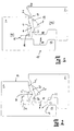
- Mit Hilfe einer Zeichnung soll ein Ausführungsbeispiel der Erfindung nachfolgend näher beschrieben werden. Es zeigt:
- Figur 1 -
- zwei Bauplatten an der Verbindungsstelle in Teilansicht mit dem einge- setzten Verriegelungselement zu Füge-Beginn;
- Figur 2 -
- die Darstellung nach
Figur 1 zu Beginn der Verriegelung; - Figur 3
- die Darstellung nach
Figur 1 bei weiter fortgeschrittener Verbindung der Bauplatten; - Figur 4 -
- die Darstellung nach
Figur 1 bei vollständiger Verbindung und Verriege- lung der beiden Bauplatten; - Die Erfindung soll für Fußbodenpaneele erläutert werden, die über die erfindungsgemäße Einrichtung sowohl an ihren Längsseiten als auch an ihren Querseiten oder aber auch nur an einer Seite miteinander verbunden werden können. Vorgesehen ist die Einrichtung zur Verbindung von Paneelen an ihren Querseiten. Die Längsseiten werden vorzugsweise durch Einwinkeln eines neuen Paneels in ein bereits am Boden liegendes Paneel und anschließendes Absenken auf den Unterboden verbunden, so wie es in der
EP 1 415 056 B1 ausführlich beschrieben ist. Die Fügebewegung an der Querseite erfolgt dann im Wesentlichen in vertikaler Richtung. - Wie die Zeichnung erkennen lässt, sind die Paneele 1, 2 an ihren Seitenkanten I, II mit zueinander korrespondierenden hakenförmigen Profilierungen 10 11 versehen. Auch wenn hier von einem ersten und einem zweiten Paneel gesprochen wird, ist jedes Paneel 1, 2 selbstverständlich identisch profiliert und die Profilierungen 10, 11 korrespondieren zueinander. Das Paneel 1 ist ausgehend von seiner Oberseite 14 profiliert und das Paneel 2 ist von seiner Unterseite 15 ausgehend profiliert. Die Profilierungen 10, 11 sind stufenförmig ausgebildet, so dass in der Profilierung 11 des ersten Paneels 1 eine nach oben offene Nut 13 mit einer sich in den Kern 17 erstreckenden horizontalen Nut 5 ausgebildet ist. Die Profilierung 10 an dem Paneel 2 bildet einen in Richtung der Unterseite 15 ragenden Absatz 18 und eine quer in die Seitenkante II eingebrachte Nut 7 aus, die im Querschnitt im Wesentlichen dreieckförmig ausgebildet ist und als Verriegelungsvertiefung dient.
- Das aus Kunststoff oder Metall bestehende Verriegelungselement 3 ist im Wesentlichen L-förmig ausgebildet und mit seinem kurzen Schenkel 3a, der an dessen inneren Ende 3" beginnt, in die Nut 5 eingesetzt. Der längere Schenkel 3b, 3c liegt mit seinem äußeren Ende 3' an dem von der Seitenkante I nach außen hervorspringenden Vorsprung 4 an. An den mit 6 und 8 gekennzeichneten Stellen kann das Verriegelungselement 3 geknickt werden, so dass sich ausgehend vom äußeren Ende 3' bis zur Knickstelle 6 ein Verriegelungsfinger 3c und von der Knickstelle 6 bis zur Knickstelle 8 ein Verschluss 3b ausbildet.
- Das Verriegelungselement 3 kann werksseitig in das Paneel 1 eingesetzt sein oder manuell beim Verlegen in die Nut 5 eingelegt werden.
- Wird das Paneel 2 zum Paneel 1 abgesenkt, stößt, wie
Figur 1 zeigt, die Unterseite 19 des am oberen Ende der Nut 7 nach außen auslaufenden Vorsprung 9 an der Seitenkante II an dem äußeren Ende 3' des Verriegelungselementes 3 an. Bei der weiteren Absenkbewegung drückt der Vorsprung 9 den Verriegelungsfinger 3c an den an der Seitenkante I des Paneels 1 ausgebildeten Vorsprung 4 an. Gleichzeitig liegt das andere Ende des Verriegelungsfingers 3c im Bereich der Verriegelurigsfläche 20 der Nut 7 am Absatz 18 an (Figur 2 ). Dabei beginnt das Verriegelungselement 3c an der Knickstelle 6 einzuknicken. Bei der weiteren Absenkbewegung drückt der Vorsprung 9 den Verriegelungsfinger 3c am Vorsprung 4 vorbei, bis die Spitze des äußeren Endes 3' an der Unterseite 4' des Vorsprungs 4 anliegt. Dabei knickt das Verriegelungselement 3c nun auch um die Knickstelle 8. Wenn der Verriegelungsfinger 3c an der Unterseite 4' des Vorsprungs 4 anliegt, greift das dem äußeren Ende 3' gegenüberliegende Ende 3''' des Verriegelungsfingers 3c in die Verriegelungsnut 7 ein. Gleichzeitig liegt der Verschluss im Bereich des Endes 3''' an der Verriegelungsfläche 20 der Nut 7 an und es wird eine formschlüssige Verriegelung zwischen den Bauplatten 1 und 2 erreicht. Durch die reproduzierbare Knickbewegung des Verriegelungselementes 3 ist es möglich, eine höhenversatzfreie Anlage der Seitenkanten I. II an der Fügestelle erreichen. - Die Verriegelung in horizontaler Richtung erfolgt über die hakenförmige Profilierung 10, 11. Der Absatz 18 stützt sich in der Nut 13 ab. Die Wandung 21 am Absatz 18 und die Wandung 16 am Absatz 12 liegen aneinander an.
-
- 1
- Paneel / Bauplatte
- 2
- Paneel / Bauplatte
- 3
- Verriegelungselement
- 3a
- Schenkel
- 3b
- Verschluss
- 3c
- Verriegelungsfinger
- 3'
- äußeres Ende
- 3"
- inneres Ende
- 3'''
- Ende
- 4
- Vorsprung
- 4'
- Unterseite
- 5
- Nut
- 6
- Stelle
- 7
- Nut / Verriegelungsvertiefung
- 8
- Stelle
- 9
- Vorsprung
- 10
- Profilierung
- 11
- Profilierung
- 12
- Vorsprung
- 13
- Nut
- 14
- Oberseite
- 15
- Unterseite
- 16
- Wandung
- 17
- Kern
- 18
- Absatz
- 19
- Unterseite
- 20
- Verriegelungsfläche
- 21
- Wandung
- I
- Seitenkante
- II
- Seitenkante
Claims (7)
- Einrichtung zur Verbindung und Verriegelung zweier Bauplatten (1, 2), insbesondere Fußbodenpaneele, an ihren Längs- und/oder Querseiten in horizontaler und vertikaler Richtung durch eine im wesentlichen vertikale Fügebewegung, wobei die Bauplatten (1, 2) eine Oberseite (14) und eine Unterseite (15) aufweisen, an ihren miteinander zu verbindenden Seitenkanten (I, II) mit zueinander korrespondierenden Profilierungen (10, 11) versehen sind und in der Profilierung (11) der ersten Bauplatte (1) ein Verriegelungselement (3) vorgesehen ist, das ein inneres Ende (3") und ein äußeres Ende (3') aufweist und mit seinem inneren Ende (3") in einer Nut (5) der ersten Baupiatte (1) eingesetzt ist, und das mit einer in der Profilierung (10) der zweiten Bauplatte (2) vorgesehenen Verriegelungsvertiefung (7) derart zusammenwirkt, dass bei der Fügebewegung die beiden Bauplatten (1, 2) selbsttätig in vertikaler Richtung verriegelt werden, dadurch gekennzeichnet, dass das Verriegelungselement (3) zur Ausbildung eines Verriegelungsfingers (3c) an einer von seinem äußeren Ende (3') entfernten Stelle (6) abknickbar ausgebildet ist, und zur Ausbildung eines Verschlusses (3b) an einer von seinem inneren Ende (3") entfernten Stelle (8) abknickbar ausgebildet ist, dass an der Seitenkante (I) der ersten Bauplatte (1) zwischen der Oberseite (14) und der Nut (5) ein nach außen hervorspringender Vorsprung (4) vorgesehen ist, dass am Ende der Fügebewegung das Verriegelungselement (3) an beiden Stellen (6, 8) abgeknickt ist und der Verriegelungsfinger (3c) mit dem äußeren Ende (3') an der Unterseite (4') des Vorsprungs (4) an der ersten Bauplatte (1) und mit seinem anderen Ende (3''') in die Verriegelungsvertiefung (7) der zweiten Bauplatte (2) eingreift und dabei der Verschluss (3c) an der Verriegelungsfläche (20) der Verriegelungsvertiefung (7) anliegt, wodurch beide Bauplatten (1, 2) in vertikaler Richtung verriegelt sind.
- Einrichtung nach Anspruch 1, dadurch gekennzeichnet, dass das Verriegelungselement (3) im Querschnitt im Wesentlichen L-förmig ausgebildet ist.
- Einrichtung nach Anspruch 2, dadurch gekennzeichnet, dass das äußere Ende (3') in Bezug zum inneren Ende (3") unter Vorspannung steht und der Verriegelungsfinger (3c) vor der Fügebewegung an dem Vorsprung (4) der ersten Bauplatte (1) anliegt.
- Einrichtung nach einem oder mehreren der vorstehenden Ansprüche, dadurch gekennzeichnet, dass das Verriegelungselement (3) aus Kunststoff besteht.
- Einrichtung nach einem oder mehreren der vorstehenden Ansprüche, dadurch gekennzeichnet, dass das Verriegelungselement (3) aus Metall besteht.
- Einrichtung nach einem oder mehreren der vorstehenden Ansprüche, dadurch gekennzeichnet, dass das innere Ende (3") in der Nut (5) einklemmt ist.
- Einrichtung nach einem oder mehreren der vorstehenden Ansprüche, dadurch gekennzeichnet, dass das innere Ende (3") in die Nut (5) eingeklebt ist.
Priority Applications (1)
| Application Number | Priority Date | Filing Date | Title |
|---|---|---|---|
| PL08015798T PL2037128T3 (pl) | 2007-09-11 | 2008-09-08 | System do łączenia i ryglowania dwóch płyt konstrukcyjnych |
Applications Claiming Priority (1)
| Application Number | Priority Date | Filing Date | Title |
|---|---|---|---|
| DE102007043308A DE102007043308B4 (de) | 2007-09-11 | 2007-09-11 | Einrichtung zur Verbindung und Verriegelung zweier Bauplatten, insbesondere Fussbodenpaneele |
Publications (2)
| Publication Number | Publication Date |
|---|---|
| EP2037128A1 true EP2037128A1 (de) | 2009-03-18 |
| EP2037128B1 EP2037128B1 (de) | 2010-01-06 |
Family
ID=39846933
Family Applications (1)
| Application Number | Title | Priority Date | Filing Date |
|---|---|---|---|
| EP08015798A Not-in-force EP2037128B1 (de) | 2007-09-11 | 2008-09-08 | Einrichtung zur Verbindung und Verriegelung zweier Bauplatten |
Country Status (6)
| Country | Link |
|---|---|
| US (1) | US8839584B2 (de) |
| EP (1) | EP2037128B1 (de) |
| AT (1) | ATE454562T1 (de) |
| DE (2) | DE102007043308B4 (de) |
| ES (1) | ES2337218T3 (de) |
| PL (1) | PL2037128T3 (de) |
Cited By (23)
| Publication number | Priority date | Publication date | Assignee | Title |
|---|---|---|---|---|
| WO2011012105A1 (de) * | 2009-07-27 | 2011-02-03 | Guido Schulte | Belag aus mechanisch miteinander verbindbaren paneelen |
| WO2011012104A3 (de) * | 2009-07-27 | 2011-04-21 | Guido Schulte | Belag aus mechanisch miteinander verbindbaren paneelen |
| CN103748298A (zh) * | 2011-08-15 | 2014-04-23 | 瓦林格地板技术股份有限公司 | 用于地板镶板的机械锁定系统 |
| DE202015101541U1 (de) | 2015-03-19 | 2015-05-05 | Guido Schulte | Mechanische Verbindung für Paneele |
| DE102014103176A1 (de) | 2014-03-10 | 2015-09-10 | Guido Schulte | Belag aus mechanisch miteinander verbindbaren Paneelen |
| WO2015171068A1 (en) | 2014-05-09 | 2015-11-12 | Floor Iptech Ab | Mechanical locking system for building panels |
| US10034541B2 (en) | 2014-12-19 | 2018-07-31 | Valinge Innovation Ab | Panels comprising a mechanical locking device and an assembled product comprising the panels |
| US10202996B2 (en) | 2011-05-06 | 2019-02-12 | Valinge Innovation Ab | Mechanical locking system for building panels |
| US10415613B2 (en) | 2016-02-09 | 2019-09-17 | Valinge Innovation Ab | Set of panel-shaped elements for a composed element |
| US10448739B2 (en) | 2015-09-22 | 2019-10-22 | Valinge Innovation Ab | Panels comprising a mechanical locking device and an assembled product comprising the panels |
| US10486245B2 (en) | 2016-02-09 | 2019-11-26 | Valinge Innovation Ab | Element and method for providing dismantling groove |
| US10544818B2 (en) | 2016-02-04 | 2020-01-28 | Valinge Innovation Ab | Set of panels for an assembled product |
| US10548397B2 (en) | 2016-01-26 | 2020-02-04 | Valinge Innovation Ab | Panels comprising a mechanical locking device and an assembled product comprising the panels |
| US10670064B2 (en) | 2015-04-21 | 2020-06-02 | Valinge Innovation Ab | Panel with a slider |
| US10724564B2 (en) | 2016-10-27 | 2020-07-28 | Valinge Innovation Ab | Set of panels with a mechanical locking device |
| EP2531667B1 (de) * | 2010-02-04 | 2020-08-26 | Välinge Innovation AB | Mechanisches verschlusssystem für bodenplatten und feder dafür |
| US10830268B2 (en) | 2014-01-10 | 2020-11-10 | Valinge Innovation Ab | Furniture panel |
| US10830266B2 (en) | 2016-02-15 | 2020-11-10 | Valinge Innovation Ab | Method for forming a panel |
| US10876563B2 (en) | 2013-09-16 | 2020-12-29 | Valinge Innovation Ab | Assembled product and a method of assembling the product |
| US10968936B2 (en) | 2015-04-30 | 2021-04-06 | Valinge Innovation Ab | Panel with a fastening device |
| US11448249B2 (en) | 2014-01-10 | 2022-09-20 | Valinge Innovation Ab | Panels comprising a mechanical locking device and an assembled product comprising the panels |
| US11506235B2 (en) | 2017-05-15 | 2022-11-22 | Valinge Innovation Ab | Elements and a locking device for an assembled product |
| US11614114B2 (en) | 2018-04-19 | 2023-03-28 | Valinge Innovation Ab | Panels for an assembled product |
Families Citing this family (66)
| Publication number | Priority date | Publication date | Assignee | Title |
|---|---|---|---|---|
| US7131242B2 (en) | 1995-03-07 | 2006-11-07 | Pergo (Europe) Ab | Flooring panel or wall panel and use thereof |
| SE9500810D0 (sv) | 1995-03-07 | 1995-03-07 | Perstorp Flooring Ab | Golvplatta |
| US7992358B2 (en) | 1998-02-04 | 2011-08-09 | Pergo AG | Guiding means at a joint |
| SE514645C2 (sv) | 1998-10-06 | 2001-03-26 | Perstorp Flooring Ab | Golvbeläggningsmaterial innefattande skivformiga golvelement avsedda att sammanfogas av separata sammanfogningsprofiler |
| SE518184C2 (sv) | 2000-03-31 | 2002-09-03 | Perstorp Flooring Ab | Golvbeläggningsmaterial innefattande skivformiga golvelement vilka sammanfogas med hjälp av sammankopplingsorgan |
| ATE467015T1 (de) | 2002-04-03 | 2010-05-15 | Vaelinge Innovation Ab | Fussbodenplatte mit integrierten verbindungsmitteln und verfahren zu deren herstellung |
| BE1017157A3 (nl) * | 2006-06-02 | 2008-03-04 | Flooring Ind Ltd | Vloerbekleding, vloerelement en werkwijze voor het vervaardigen van vloerelementen. |
| SE533410C2 (sv) | 2006-07-11 | 2010-09-14 | Vaelinge Innovation Ab | Golvpaneler med mekaniska låssystem med en flexibel och förskjutbar tunga samt tunga därför |
| US8689512B2 (en) | 2006-11-15 | 2014-04-08 | Valinge Innovation Ab | Mechanical locking of floor panels with vertical folding |
| US11725394B2 (en) | 2006-11-15 | 2023-08-15 | Välinge Innovation AB | Mechanical locking of floor panels with vertical folding |
| SE531111C2 (sv) | 2006-12-08 | 2008-12-23 | Vaelinge Innovation Ab | Mekanisk låsning av golvpaneler |
| DE102009022483A1 (de) * | 2009-05-25 | 2010-12-02 | Pergo (Europe) Ab | Set von Paneelen, insbesondere von Fußbodenpaneelen |
| DE102009041297B4 (de) * | 2009-09-15 | 2018-10-11 | Guido Schulte | Belag aus mechanisch miteinander verbindbaren Elementen und ein Verfahren zur Herstellung von Elementen |
| DE102009048050B3 (de) * | 2009-10-02 | 2011-01-20 | Guido Schulte | Belag aus mechanischen miteinander verbindbaren Elementen |
| US8544230B2 (en) | 2010-01-12 | 2013-10-01 | Valinge Innovation Ab | Mechanical locking system for floor panels |
| CA2786768C (en) * | 2010-01-14 | 2018-09-04 | Unilin, Bvba | Floor panel assembly and floor panel for use therein |
| DE102010004717A1 (de) | 2010-01-15 | 2011-07-21 | Pergo (Europe) Ab | Set aus Paneelen umfassend Halteprofile mit einem separaten Clip sowie Verfahren zum Einbringen des Clips |
| DE202010017935U1 (de) | 2010-04-15 | 2013-03-27 | Spanolux N.V. Div. Balterio | Bodenplattenanordnung |
| DE202010018028U1 (de) | 2010-04-15 | 2013-09-17 | Spanolux N.V. Div. Balterio | Bodenplattenanordnung |
| CN102844506B (zh) | 2010-04-15 | 2015-08-12 | 巴尔特利奥-斯巴诺吕克斯股份公司 | 地板组件 |
| BE1019331A5 (nl) | 2010-05-10 | 2012-06-05 | Flooring Ind Ltd Sarl | Vloerpaneel en werkwijzen voor het vervaardigen van vloerpanelen. |
| CN104775594B (zh) | 2010-05-10 | 2017-09-22 | 佩尔戈(欧洲)股份公司 | 地板组件 |
| US8591696B2 (en) | 2010-11-17 | 2013-11-26 | Pergo (Europe) Ab | Method for manufacturing a surface element |
| US8806832B2 (en) | 2011-03-18 | 2014-08-19 | Inotec Global Limited | Vertical joint system and associated surface covering system |
| UA114715C2 (uk) * | 2011-07-05 | 2017-07-25 | Сералок Інновейшн Аб | Механічна фіксація панелей настилу підлоги до язичка з нанесеним шаром клею |
| US9725912B2 (en) | 2011-07-11 | 2017-08-08 | Ceraloc Innovation Ab | Mechanical locking system for floor panels |
| US8650826B2 (en) | 2011-07-19 | 2014-02-18 | Valinge Flooring Technology Ab | Mechanical locking system for floor panels |
| US8857126B2 (en) | 2011-08-15 | 2014-10-14 | Valinge Flooring Technology Ab | Mechanical locking system for floor panels |
| BR112014003962B1 (pt) | 2011-08-29 | 2021-04-13 | Ceraloc Innovation Ab | Painéis de piso proporcionados com um sistema de travamento |
| DE102011056494A1 (de) * | 2011-12-15 | 2013-06-20 | Pergo (Europe) Ab | Set aus Paneelen mit Clip |
| BE1020433A3 (nl) * | 2012-01-05 | 2013-10-01 | Flooring Ind Ltd Sarl | Paneel. |
| CN109025154B (zh) | 2012-06-19 | 2021-04-02 | 瓦林格创新股份有限公司 | 将板块分为第一和第二镶板的方法、形成机械锁定系统的方法以及建筑镶板 |
| DK3091141T3 (en) | 2012-07-02 | 2018-08-13 | Ceraloc Innovation Ab | FLOOR PANELS WITH REDUCED WEIGHT AND MATERIAL CONTENT |
| US9140010B2 (en) | 2012-07-02 | 2015-09-22 | Valinge Flooring Technology Ab | Panel forming |
| EP2895667B1 (de) | 2012-08-27 | 2019-12-04 | Pergo (Europe) AB | Tafel |
| CN104854286B (zh) | 2012-11-22 | 2018-04-13 | 塞拉洛克创新股份有限公司 | 用于地板镶板的机械锁定系统 |
| DE102013101756A1 (de) * | 2012-11-30 | 2014-06-05 | Hamberger Industriewerke Gmbh | Verbindung und Verriegelungselement |
| EP3014034B1 (de) | 2013-06-27 | 2019-10-02 | Välinge Innovation AB | Bauplatte mit einem mechanischen arretierungssystem |
| DE102013108539A1 (de) * | 2013-08-07 | 2015-02-12 | Hamberger Industriewerke Gmbh | Verbindung und Verriegelungselement |
| DK3047160T3 (en) | 2013-09-16 | 2019-04-08 | Vaelinge Innovation Ab | TOTAL FURNITURE PRODUCT |
| WO2015070890A1 (en) * | 2013-11-12 | 2015-05-21 | Grigorij Wagner | Flooring component |
| EP2915934A1 (de) * | 2014-03-06 | 2015-09-09 | Flooring Industries Ltd., SARL. | Set aus Paneelen mit Verriegelungselement |
| US10246883B2 (en) * | 2014-05-14 | 2019-04-02 | Valinge Innovation Ab | Building panel with a mechanical locking system |
| KR102386246B1 (ko) * | 2014-05-14 | 2022-04-12 | 뵈린게 이노베이션 에이비이 | 기계식 록킹 시스템이 구비된 빌딩 패널 |
| CN107002411B (zh) | 2014-11-27 | 2020-06-16 | 瓦林格创新股份有限公司 | 用于地板镶板的机械锁定系统 |
| MX2018006522A (es) | 2015-12-03 | 2018-11-29 | Vaelinge Innovation Ab | Paneles que comprenden un dispositivo de bloqueo mecanico y un producto ensamblado que comprende los paneles. |
| DE102016114226A1 (de) * | 2016-01-22 | 2017-07-27 | Hamberger Industriewerke Gmbh | Verbindung für elastische oder feste Bauelemente |
| JP7438949B2 (ja) | 2017-12-22 | 2024-02-27 | ベーリンゲ、イノベイション、アクチボラグ | パネルのセット、パネルのセットの組み立ての方法、及び家具製品のための固定装置 |
| WO2019125292A1 (en) | 2017-12-22 | 2019-06-27 | Välinge Innovation AB | A set of panels, a method for assembly of the same and a locking device for a furniture product. |
| NO20172047A1 (no) | 2017-12-24 | 2019-06-25 | Humeneq As | Oppfinnelsen angår en klikkanordning for benkeplate- og andre plateskjøter. |
| CA3094060A1 (en) | 2018-03-23 | 2019-09-26 | Valinge Innovation Ab | Panels comprising a mechanical locking device and an assembled product comprising the panels |
| EP3781824B1 (de) | 2018-04-18 | 2024-04-10 | Välinge Innovation AB | Satz aus platten mit mechanischer verriegelungsvorrichtung |
| WO2019203720A1 (en) | 2018-04-18 | 2019-10-24 | Välinge Innovation AB | Symmetric tongue & t-cross |
| EP3781823B1 (de) | 2018-04-18 | 2024-04-10 | Välinge Innovation AB | Satz aus platten mit mechanischer verriegelungsvorrichtung |
| PL3781822T3 (pl) | 2018-04-18 | 2024-11-18 | Välinge Innovation AB | Zestaw paneli z mechanicznym urządzeniem blokującym |
| SI3844407T1 (sl) | 2018-08-30 | 2024-06-28 | Vaelinge Innovation AB, | Komplet plošč z mehansko zaklepno napravo |
| US12495898B2 (en) | 2018-08-30 | 2025-12-16 | Välinge Innovation AB | Set of panels with a mechanical locking device |
| BE1026806B1 (nl) * | 2018-11-27 | 2020-06-30 | Flooring Ind Ltd Sarl | Paneel en werkwijze voor het vervaardigen van dergelijk paneel |
| US11060302B2 (en) | 2019-01-10 | 2021-07-13 | Valinge Innovation Ab | Unlocking system for panels |
| BE1027032B1 (nl) * | 2019-02-07 | 2020-09-07 | Flooring Ind Ltd Sarl | Paneel en bekleding gevormd met dergelijke panelen |
| WO2020180237A1 (en) | 2019-03-05 | 2020-09-10 | Ceraloc Innovation Ab | Methods for forming grooves in a board element and an associated panel |
| EP3708739B1 (de) | 2019-03-12 | 2021-02-17 | Flooring Technologies Ltd. | Hartes fussbodenpaneel zur schwimmenden verlegung unter ausbildung eines fussbodenpaneelverbundes |
| CA3134101A1 (en) | 2019-03-25 | 2020-10-01 | Ceraloc Innovation Ab | A mineral-based panel comprising grooves and a method for forming grooves |
| US11725398B2 (en) | 2019-12-27 | 2023-08-15 | Ceraloc Innovation Ab | Thermoplastic-based building panel comprising a balancing layer |
| EP3971364A1 (de) * | 2020-09-17 | 2022-03-23 | Surface Technologies GmbH & Co. KG | Paneel |
| CA3206480A1 (en) * | 2021-02-03 | 2022-08-11 | Valinge Innovation Ab | Building panels comprising a locking device |
Citations (3)
| Publication number | Priority date | Publication date | Assignee | Title |
|---|---|---|---|---|
| EP1415056B1 (de) | 2001-08-10 | 2006-01-11 | Akzenta Paneele + Profile GmbH | Paneel sowie Befestigungssystem für Paneele |
| DE102006011887A1 (de) * | 2006-01-13 | 2007-07-19 | Akzenta Paneele + Profile Gmbh | Sperrelement, Paneel mit separatem Sperrelement, Verfahren zur Installation eines Paneelbelags aus Paneelen mit Sperrelementen sowie Verfahren und Vorrichtung zur Vormontage eines Sperrelements an einem Paneel |
| WO2007089186A1 (en) * | 2006-02-03 | 2007-08-09 | Pergo (Europe) Ab | A joint guard for panels |
Family Cites Families (4)
| Publication number | Priority date | Publication date | Assignee | Title |
|---|---|---|---|---|
| SE515789C2 (sv) * | 1999-02-10 | 2001-10-08 | Perstorp Flooring Ab | Golvbeläggningsmaterial innefattande golvelement vilka är avsedda att sammanfogas vertikalt |
| ATE395481T1 (de) * | 2002-11-15 | 2008-05-15 | Flooring Technologies Ltd | Einrichtung bestehend aus zwei miteinander verbindbaren bauplatten und einem einsatz zum verriegeln dieser bauplatten |
| US7841144B2 (en) * | 2005-03-30 | 2010-11-30 | Valinge Innovation Ab | Mechanical locking system for panels and method of installing same |
| US7726088B2 (en) * | 2007-07-20 | 2010-06-01 | Moritz Andre Muehlebach | Flooring system |
-
2007
- 2007-09-11 DE DE102007043308A patent/DE102007043308B4/de not_active Expired - Fee Related
-
2008
- 2008-09-04 US US12/204,195 patent/US8839584B2/en active Active
- 2008-09-08 PL PL08015798T patent/PL2037128T3/pl unknown
- 2008-09-08 EP EP08015798A patent/EP2037128B1/de not_active Not-in-force
- 2008-09-08 ES ES08015798T patent/ES2337218T3/es active Active
- 2008-09-08 AT AT08015798T patent/ATE454562T1/de active
- 2008-09-08 DE DE502008000298T patent/DE502008000298D1/de active Active
Patent Citations (3)
| Publication number | Priority date | Publication date | Assignee | Title |
|---|---|---|---|---|
| EP1415056B1 (de) | 2001-08-10 | 2006-01-11 | Akzenta Paneele + Profile GmbH | Paneel sowie Befestigungssystem für Paneele |
| DE102006011887A1 (de) * | 2006-01-13 | 2007-07-19 | Akzenta Paneele + Profile Gmbh | Sperrelement, Paneel mit separatem Sperrelement, Verfahren zur Installation eines Paneelbelags aus Paneelen mit Sperrelementen sowie Verfahren und Vorrichtung zur Vormontage eines Sperrelements an einem Paneel |
| WO2007089186A1 (en) * | 2006-02-03 | 2007-08-09 | Pergo (Europe) Ab | A joint guard for panels |
Cited By (37)
| Publication number | Priority date | Publication date | Assignee | Title |
|---|---|---|---|---|
| WO2011012104A3 (de) * | 2009-07-27 | 2011-04-21 | Guido Schulte | Belag aus mechanisch miteinander verbindbaren paneelen |
| US9109366B2 (en) | 2009-07-27 | 2015-08-18 | Guido Schulte | Covering made from mechanically interconnectable panels |
| WO2011012105A1 (de) * | 2009-07-27 | 2011-02-03 | Guido Schulte | Belag aus mechanisch miteinander verbindbaren paneelen |
| EP2531667B1 (de) * | 2010-02-04 | 2020-08-26 | Välinge Innovation AB | Mechanisches verschlusssystem für bodenplatten und feder dafür |
| US10202996B2 (en) | 2011-05-06 | 2019-02-12 | Valinge Innovation Ab | Mechanical locking system for building panels |
| US11781577B2 (en) | 2011-05-06 | 2023-10-10 | Valinge Innovation Ab | Mechanical locking system for building panels |
| US12276293B2 (en) | 2011-05-06 | 2025-04-15 | Välinge Innovation AB | Mechanical locking system for building panels |
| CN103748298A (zh) * | 2011-08-15 | 2014-04-23 | 瓦林格地板技术股份有限公司 | 用于地板镶板的机械锁定系统 |
| CN103748298B (zh) * | 2011-08-15 | 2016-08-17 | 塞拉洛克创新股份有限公司 | 用于地板镶板的机械锁定系统 |
| US10876563B2 (en) | 2013-09-16 | 2020-12-29 | Valinge Innovation Ab | Assembled product and a method of assembling the product |
| US10830268B2 (en) | 2014-01-10 | 2020-11-10 | Valinge Innovation Ab | Furniture panel |
| US11448249B2 (en) | 2014-01-10 | 2022-09-20 | Valinge Innovation Ab | Panels comprising a mechanical locking device and an assembled product comprising the panels |
| WO2015135533A1 (de) | 2014-03-10 | 2015-09-17 | Guido Schulte | Belag aus mechanisch miteinander verbindbaren paneelen |
| DE102014103176A1 (de) | 2014-03-10 | 2015-09-10 | Guido Schulte | Belag aus mechanisch miteinander verbindbaren Paneelen |
| US11326636B2 (en) | 2014-05-09 | 2022-05-10 | Valinge Innovation Ab | Mechanical locking system for building panels |
| CN106460901A (zh) * | 2014-05-09 | 2017-02-22 | 瓦林格创新股份有限公司 | 用于建筑镶板的机械锁定系统 |
| US11885355B2 (en) | 2014-05-09 | 2024-01-30 | Välinge Innovation AB | Mechanical locking system for building panels |
| EP3851684A1 (de) * | 2014-05-09 | 2021-07-21 | Välinge Innovation AB | Mechanisches verschlusssystem für bauplatten |
| WO2015171068A1 (en) | 2014-05-09 | 2015-11-12 | Floor Iptech Ab | Mechanical locking system for building panels |
| US10876562B2 (en) | 2014-05-09 | 2020-12-29 | Valinge Innovation Ab | Mechanical locking system for building panels |
| EP3140555A4 (de) * | 2014-05-09 | 2018-03-07 | Välinge Innovation AB | Mechanisches verschlusssystem für bodenplatten |
| US10034541B2 (en) | 2014-12-19 | 2018-07-31 | Valinge Innovation Ab | Panels comprising a mechanical locking device and an assembled product comprising the panels |
| WO2016146112A1 (de) | 2015-03-19 | 2016-09-22 | Guido Schulte | Mechanische verbindung für paneele und verfahren zur herstellung von verbindungsmitteln |
| DE102015106794A1 (de) | 2015-03-19 | 2016-09-22 | Guido Schulte | Mechanische Verbindung für Paneele und Verfahren zur Herstellung von Verbindungsmitteln |
| DE202015101541U1 (de) | 2015-03-19 | 2015-05-05 | Guido Schulte | Mechanische Verbindung für Paneele |
| US10670064B2 (en) | 2015-04-21 | 2020-06-02 | Valinge Innovation Ab | Panel with a slider |
| US10968936B2 (en) | 2015-04-30 | 2021-04-06 | Valinge Innovation Ab | Panel with a fastening device |
| US10448739B2 (en) | 2015-09-22 | 2019-10-22 | Valinge Innovation Ab | Panels comprising a mechanical locking device and an assembled product comprising the panels |
| US10548397B2 (en) | 2016-01-26 | 2020-02-04 | Valinge Innovation Ab | Panels comprising a mechanical locking device and an assembled product comprising the panels |
| US12453413B2 (en) | 2016-01-26 | 2025-10-28 | Välinge Innovation AB | Panels comprising a mechanical locking device and an assembled product comprising the panels |
| US10544818B2 (en) | 2016-02-04 | 2020-01-28 | Valinge Innovation Ab | Set of panels for an assembled product |
| US10486245B2 (en) | 2016-02-09 | 2019-11-26 | Valinge Innovation Ab | Element and method for providing dismantling groove |
| US10415613B2 (en) | 2016-02-09 | 2019-09-17 | Valinge Innovation Ab | Set of panel-shaped elements for a composed element |
| US10830266B2 (en) | 2016-02-15 | 2020-11-10 | Valinge Innovation Ab | Method for forming a panel |
| US10724564B2 (en) | 2016-10-27 | 2020-07-28 | Valinge Innovation Ab | Set of panels with a mechanical locking device |
| US11506235B2 (en) | 2017-05-15 | 2022-11-22 | Valinge Innovation Ab | Elements and a locking device for an assembled product |
| US11614114B2 (en) | 2018-04-19 | 2023-03-28 | Valinge Innovation Ab | Panels for an assembled product |
Also Published As
| Publication number | Publication date |
|---|---|
| EP2037128B1 (de) | 2010-01-06 |
| PL2037128T3 (pl) | 2010-07-30 |
| DE102007043308B4 (de) | 2009-12-03 |
| US8839584B2 (en) | 2014-09-23 |
| ATE454562T1 (de) | 2010-01-15 |
| DE102007043308A1 (de) | 2009-03-12 |
| US20090064624A1 (en) | 2009-03-12 |
| ES2337218T3 (es) | 2010-04-21 |
| DE502008000298D1 (de) | 2010-02-25 |
Similar Documents
| Publication | Publication Date | Title |
|---|---|---|
| EP2037128B1 (de) | Einrichtung zur Verbindung und Verriegelung zweier Bauplatten | |
| EP2034106B1 (de) | Einrichtung zur Verbindung und Verriegelung zweier Bauplatten, insbesondere Fußbodenpanelle | |
| EP2459815B1 (de) | Belag aus mechanisch miteinander verbindbaren paneelen | |
| DE10101202B4 (de) | Parkettplatte | |
| EP2270291B1 (de) | Satz aus Bauplatten mit einer Einrichtung zum Verriegeln zweier dieser Bauplatten | |
| DE69413391T2 (de) | Verbindungssystem für gebäudeplatten | |
| EP2078801B1 (de) | Einrichtung zum Verriegeln zweier Bauplatten | |
| EP1242701B1 (de) | Verbindung | |
| DE10159284B4 (de) | Gebäudeplatte, insbesondere Bodenpaneel | |
| DE102009034902B4 (de) | Belag aus mechanisch miteinander verbindbaren Paneelen | |
| DE20002413U1 (de) | Verbindung | |
| DE212010000195U1 (de) | Bodenplattenanordnung | |
| DE10206877A1 (de) | Paneel, insbesondere Fussbodenpaneel | |
| DE20203311U1 (de) | Paneelelement | |
| EP3856998A1 (de) | Fussbodenpaneel mit separatem clip für die vertikale verriegelung | |
| DE102011122086A1 (de) | System bestehend aus zwei miteinander verbundenen und verriegelten Bauplatten mit einem Verriegelungselement | |
| DE20121196U1 (de) | Gebäudeplatte, insbesondere Bodenpaneel | |
| DE3226791A1 (de) | Stuetz- und befestigungselement fuer die wandseitige befestigung einer badewanne, insbesondere einer kunststoffbadewanne | |
| DE102016115886A1 (de) | Plattenförmiges Bauelement | |
| EP3080365A1 (de) | Paneel mit verriegelungselement | |
| DE20200268U1 (de) | Paneelelement | |
| EP3670783A1 (de) | Montageclip zur schwimmenden lagerung von wand- und deckenpaneelen | |
| DE10154767A1 (de) | Fussbodenpaneel | |
| EP1241303B1 (de) | Fussbodenpaneel | |
| EP2194203B1 (de) | Bauplatte, insbesondere Fassadenplatte als Wärme/Schalldämmung für Außenfassaden, sowie Verfahren zum Verlegen solcher Bauplatten |
Legal Events
| Date | Code | Title | Description |
|---|---|---|---|
| PUAI | Public reference made under article 153(3) epc to a published international application that has entered the european phase |
Free format text: ORIGINAL CODE: 0009012 |
|
| 17P | Request for examination filed |
Effective date: 20090107 |
|
| AK | Designated contracting states |
Kind code of ref document: A1 Designated state(s): AT BE BG CH CY CZ DE DK EE ES FI FR GB GR HR HU IE IS IT LI LT LU LV MC MT NL NO PL PT RO SE SI SK TR |
|
| AX | Request for extension of the european patent |
Extension state: AL BA MK RS |
|
| GRAP | Despatch of communication of intention to grant a patent |
Free format text: ORIGINAL CODE: EPIDOSNIGR1 |
|
| GRAS | Grant fee paid |
Free format text: ORIGINAL CODE: EPIDOSNIGR3 |
|
| AKX | Designation fees paid |
Designated state(s): AT BE BG CH CY CZ DE DK EE ES FI FR GB GR HR HU IE IS IT LI LT LU LV MC MT NL NO PL PT RO SE SI SK TR |
|
| GRAA | (expected) grant |
Free format text: ORIGINAL CODE: 0009210 |
|
| AK | Designated contracting states |
Kind code of ref document: B1 Designated state(s): AT BE BG CH CY CZ DE DK EE ES FI FR GB GR HR HU IE IS IT LI LT LU LV MC MT NL NO PL PT RO SE SI SK TR |
|
| REG | Reference to a national code |
Ref country code: GB Ref legal event code: FG4D Free format text: NOT ENGLISH |
|
| REG | Reference to a national code |
Ref country code: CH Ref legal event code: EP |
|
| REG | Reference to a national code |
Ref country code: CH Ref legal event code: NV Representative=s name: BRAUNPAT BRAUN EDER AG |
|
| REG | Reference to a national code |
Ref country code: IE Ref legal event code: FG4D |
|
| REF | Corresponds to: |
Ref document number: 502008000298 Country of ref document: DE Date of ref document: 20100225 Kind code of ref document: P |
|
| REG | Reference to a national code |
Ref country code: ES Ref legal event code: FG2A Ref document number: 2337218 Country of ref document: ES Kind code of ref document: T3 |
|
| REG | Reference to a national code |
Ref country code: NL Ref legal event code: VDEP Effective date: 20100106 |
|
| PG25 | Lapsed in a contracting state [announced via postgrant information from national office to epo] |
Ref country code: SI Free format text: LAPSE BECAUSE OF FAILURE TO SUBMIT A TRANSLATION OF THE DESCRIPTION OR TO PAY THE FEE WITHIN THE PRESCRIBED TIME-LIMIT Effective date: 20100106 |
|
| LTIE | Lt: invalidation of european patent or patent extension |
Effective date: 20100106 |
|
| PG25 | Lapsed in a contracting state [announced via postgrant information from national office to epo] |
Ref country code: IS Free format text: LAPSE BECAUSE OF FAILURE TO SUBMIT A TRANSLATION OF THE DESCRIPTION OR TO PAY THE FEE WITHIN THE PRESCRIBED TIME-LIMIT Effective date: 20100506 Ref country code: HR Free format text: LAPSE BECAUSE OF FAILURE TO SUBMIT A TRANSLATION OF THE DESCRIPTION OR TO PAY THE FEE WITHIN THE PRESCRIBED TIME-LIMIT Effective date: 20100106 Ref country code: LT Free format text: LAPSE BECAUSE OF FAILURE TO SUBMIT A TRANSLATION OF THE DESCRIPTION OR TO PAY THE FEE WITHIN THE PRESCRIBED TIME-LIMIT Effective date: 20100106 Ref country code: NL Free format text: LAPSE BECAUSE OF FAILURE TO SUBMIT A TRANSLATION OF THE DESCRIPTION OR TO PAY THE FEE WITHIN THE PRESCRIBED TIME-LIMIT Effective date: 20100106 Ref country code: NO Free format text: LAPSE BECAUSE OF FAILURE TO SUBMIT A TRANSLATION OF THE DESCRIPTION OR TO PAY THE FEE WITHIN THE PRESCRIBED TIME-LIMIT Effective date: 20100406 |
|
| REG | Reference to a national code |
Ref country code: PL Ref legal event code: T3 |
|
| REG | Reference to a national code |
Ref country code: IE Ref legal event code: FD4D |
|
| PG25 | Lapsed in a contracting state [announced via postgrant information from national office to epo] |
Ref country code: FI Free format text: LAPSE BECAUSE OF FAILURE TO SUBMIT A TRANSLATION OF THE DESCRIPTION OR TO PAY THE FEE WITHIN THE PRESCRIBED TIME-LIMIT Effective date: 20100106 Ref country code: LV Free format text: LAPSE BECAUSE OF FAILURE TO SUBMIT A TRANSLATION OF THE DESCRIPTION OR TO PAY THE FEE WITHIN THE PRESCRIBED TIME-LIMIT Effective date: 20100106 |
|
| PG25 | Lapsed in a contracting state [announced via postgrant information from national office to epo] |
Ref country code: IE Free format text: LAPSE BECAUSE OF FAILURE TO SUBMIT A TRANSLATION OF THE DESCRIPTION OR TO PAY THE FEE WITHIN THE PRESCRIBED TIME-LIMIT Effective date: 20100106 Ref country code: EE Free format text: LAPSE BECAUSE OF FAILURE TO SUBMIT A TRANSLATION OF THE DESCRIPTION OR TO PAY THE FEE WITHIN THE PRESCRIBED TIME-LIMIT Effective date: 20100106 Ref country code: RO Free format text: LAPSE BECAUSE OF FAILURE TO SUBMIT A TRANSLATION OF THE DESCRIPTION OR TO PAY THE FEE WITHIN THE PRESCRIBED TIME-LIMIT Effective date: 20100106 Ref country code: SE Free format text: LAPSE BECAUSE OF FAILURE TO SUBMIT A TRANSLATION OF THE DESCRIPTION OR TO PAY THE FEE WITHIN THE PRESCRIBED TIME-LIMIT Effective date: 20100106 Ref country code: CY Free format text: LAPSE BECAUSE OF FAILURE TO SUBMIT A TRANSLATION OF THE DESCRIPTION OR TO PAY THE FEE WITHIN THE PRESCRIBED TIME-LIMIT Effective date: 20100106 |
|
| PLBE | No opposition filed within time limit |
Free format text: ORIGINAL CODE: 0009261 |
|
| STAA | Information on the status of an ep patent application or granted ep patent |
Free format text: STATUS: NO OPPOSITION FILED WITHIN TIME LIMIT |
|
| PG25 | Lapsed in a contracting state [announced via postgrant information from national office to epo] |
Ref country code: SK Free format text: LAPSE BECAUSE OF FAILURE TO SUBMIT A TRANSLATION OF THE DESCRIPTION OR TO PAY THE FEE WITHIN THE PRESCRIBED TIME-LIMIT Effective date: 20100106 Ref country code: CZ Free format text: LAPSE BECAUSE OF FAILURE TO SUBMIT A TRANSLATION OF THE DESCRIPTION OR TO PAY THE FEE WITHIN THE PRESCRIBED TIME-LIMIT Effective date: 20100106 Ref country code: BG Free format text: LAPSE BECAUSE OF FAILURE TO SUBMIT A TRANSLATION OF THE DESCRIPTION OR TO PAY THE FEE WITHIN THE PRESCRIBED TIME-LIMIT Effective date: 20100406 |
|
| 26N | No opposition filed |
Effective date: 20101007 |
|
| PG25 | Lapsed in a contracting state [announced via postgrant information from national office to epo] |
Ref country code: DK Free format text: LAPSE BECAUSE OF FAILURE TO SUBMIT A TRANSLATION OF THE DESCRIPTION OR TO PAY THE FEE WITHIN THE PRESCRIBED TIME-LIMIT Effective date: 20100106 |
|
| PG25 | Lapsed in a contracting state [announced via postgrant information from national office to epo] |
Ref country code: IT Free format text: LAPSE BECAUSE OF FAILURE TO SUBMIT A TRANSLATION OF THE DESCRIPTION OR TO PAY THE FEE WITHIN THE PRESCRIBED TIME-LIMIT Effective date: 20100106 |
|
| PG25 | Lapsed in a contracting state [announced via postgrant information from national office to epo] |
Ref country code: MC Free format text: LAPSE BECAUSE OF NON-PAYMENT OF DUE FEES Effective date: 20100930 |
|
| PG25 | Lapsed in a contracting state [announced via postgrant information from national office to epo] |
Ref country code: MT Free format text: LAPSE BECAUSE OF FAILURE TO SUBMIT A TRANSLATION OF THE DESCRIPTION OR TO PAY THE FEE WITHIN THE PRESCRIBED TIME-LIMIT Effective date: 20100106 |
|
| REG | Reference to a national code |
Ref country code: DE Ref legal event code: R082 Ref document number: 502008000298 Country of ref document: DE Representative=s name: GRAMM, LINS & PARTNER PATENT- UND RECHTSANWAEL, DE Effective date: 20120322 Ref country code: DE Ref legal event code: R081 Ref document number: 502008000298 Country of ref document: DE Owner name: FLOORING TECHNOLOGIES LTD., MT Free format text: FORMER OWNER: FLOORING TECHNOLOGIES LTD., PIETA, MT Effective date: 20120322 Ref country code: DE Ref legal event code: R082 Ref document number: 502008000298 Country of ref document: DE Representative=s name: GRAMM, LINS & PARTNER GBR, DE Effective date: 20120322 |
|
| PG25 | Lapsed in a contracting state [announced via postgrant information from national office to epo] |
Ref country code: HU Free format text: LAPSE BECAUSE OF FAILURE TO SUBMIT A TRANSLATION OF THE DESCRIPTION OR TO PAY THE FEE WITHIN THE PRESCRIBED TIME-LIMIT Effective date: 20100707 Ref country code: LU Free format text: LAPSE BECAUSE OF NON-PAYMENT OF DUE FEES Effective date: 20100908 |
|
| REG | Reference to a national code |
Ref country code: CH Ref legal event code: PUE Owner name: FALQUON GMBH Free format text: FLOORING TECHNOLOGIES LTD.# #PORTICO BUILDING MARINA STREET PIETA MSD 08 (MT) -TRANSFER TO- FALQUON GMBH#AM HUENENGRAB 18#16928 PRITZWALK (DE) |
|
| REG | Reference to a national code |
Ref country code: GB Ref legal event code: 732E Free format text: REGISTERED BETWEEN 20121004 AND 20121010 |
|
| REG | Reference to a national code |
Ref country code: ES Ref legal event code: PC2A Owner name: FALQUON GMBH Effective date: 20121030 |
|
| REG | Reference to a national code |
Ref country code: FR Ref legal event code: TP Owner name: FALQUON GMBH, DE Effective date: 20121017 |
|
| REG | Reference to a national code |
Ref country code: AT Ref legal event code: PC Ref document number: 454562 Country of ref document: AT Kind code of ref document: T Owner name: FALQUON GMBH, DE Effective date: 20130312 |
|
| PG25 | Lapsed in a contracting state [announced via postgrant information from national office to epo] |
Ref country code: PT Free format text: LAPSE BECAUSE OF NON-PAYMENT OF DUE FEES Effective date: 20100106 |
|
| REG | Reference to a national code |
Ref country code: DE Ref legal event code: R082 Ref document number: 502008000298 Country of ref document: DE Representative=s name: GRAMM, LINS & PARTNER GBR, DE |
|
| REG | Reference to a national code |
Ref country code: DE Ref legal event code: R081 Ref document number: 502008000298 Country of ref document: DE Owner name: FLOORING TECHNOLOGIES LTD., MT Free format text: FORMER OWNER: FALQUON GMBH, 16928 PRITZWALK, DE Effective date: 20131209 Ref country code: DE Ref legal event code: R082 Ref document number: 502008000298 Country of ref document: DE Representative=s name: GRAMM, LINS & PARTNER GBR, DE Effective date: 20131209 Ref country code: DE Ref legal event code: R082 Ref document number: 502008000298 Country of ref document: DE Representative=s name: GRAMM, LINS & PARTNER PATENT- UND RECHTSANWAEL, DE Effective date: 20131209 |
|
| PG25 | Lapsed in a contracting state [announced via postgrant information from national office to epo] |
Ref country code: GR Free format text: LAPSE BECAUSE OF FAILURE TO SUBMIT A TRANSLATION OF THE DESCRIPTION OR TO PAY THE FEE WITHIN THE PRESCRIBED TIME-LIMIT Effective date: 20100106 |
|
| REG | Reference to a national code |
Ref country code: CH Ref legal event code: PUE Owner name: FLOORING TECHNOLOGIES LTD., MT Free format text: FORMER OWNER: FALQUON GMBH, DE |
|
| REG | Reference to a national code |
Ref country code: FR Ref legal event code: TP Owner name: FLOORING TECHNOLOGIES LTD., MT Effective date: 20140922 |
|
| REG | Reference to a national code |
Ref country code: GB Ref legal event code: 732E Free format text: REGISTERED BETWEEN 20141113 AND 20141119 |
|
| REG | Reference to a national code |
Ref country code: ES Ref legal event code: PC2A Owner name: FLOORING TECHNOLOGIES LTD. Effective date: 20150130 |
|
| REG | Reference to a national code |
Ref country code: DE Ref legal event code: R082 Ref document number: 502008000298 Country of ref document: DE Representative=s name: GRAMM, LINS & PARTNER PATENT- UND RECHTSANWAEL, DE |
|
| REG | Reference to a national code |
Ref country code: AT Ref legal event code: PC Ref document number: 454562 Country of ref document: AT Kind code of ref document: T Owner name: FLOORING TECHNOLOGIES LTD., MT Effective date: 20150818 |
|
| REG | Reference to a national code |
Ref country code: FR Ref legal event code: PLFP Year of fee payment: 9 |
|
| REG | Reference to a national code |
Ref country code: FR Ref legal event code: PLFP Year of fee payment: 10 |
|
| REG | Reference to a national code |
Ref country code: DE Ref legal event code: R082 Ref document number: 502008000298 Country of ref document: DE Representative=s name: GRAMM, LINS & PARTNER PATENT- UND RECHTSANWAEL, DE Ref country code: DE Ref legal event code: R081 Ref document number: 502008000298 Country of ref document: DE Owner name: FLOORING TECHNOLOGIES LTD., MT Free format text: FORMER OWNER: FLOORING TECHNOLOGIES LTD., PIETA, MT |
|
| REG | Reference to a national code |
Ref country code: CH Ref legal event code: PCOW Free format text: NEW ADDRESS: SMARTCITY MALTA SCM01, OFFICE 406, RICASOLI, KALKARA SCM 1001 (MT) |
|
| REG | Reference to a national code |
Ref country code: BE Ref legal event code: PD Owner name: FLOORING TECHNOLOGIES LTD.; MT Free format text: DETAILS ASSIGNMENT: CHANGE OF OWNER(S), AUTRE, ADRESSE; FORMER OWNER NAME: FLOORING TECHNOLOGIES LTD. Effective date: 20170921 Ref country code: BE Ref legal event code: PD Owner name: FLOORING TECHNOLOGIES LTD.; MT Free format text: DETAILS ASSIGNMENT: CHANGE OF OWNER(S), AFFECTATION / CESSION; FORMER OWNER NAME: FALQUON GMBH Effective date: 20150320 |
|
| REG | Reference to a national code |
Ref country code: CH Ref legal event code: PCAR Free format text: NEW ADDRESS: HOLEESTRASSE 87, 4054 BASEL (CH) |
|
| REG | Reference to a national code |
Ref country code: FR Ref legal event code: PLFP Year of fee payment: 11 |
|
| PGFP | Annual fee paid to national office [announced via postgrant information from national office to epo] |
Ref country code: FR Payment date: 20200921 Year of fee payment: 13 Ref country code: GB Payment date: 20200923 Year of fee payment: 13 Ref country code: TR Payment date: 20200907 Year of fee payment: 13 |
|
| PGFP | Annual fee paid to national office [announced via postgrant information from national office to epo] |
Ref country code: AT Payment date: 20200918 Year of fee payment: 13 Ref country code: BE Payment date: 20200921 Year of fee payment: 13 Ref country code: CH Payment date: 20200925 Year of fee payment: 13 |
|
| PGFP | Annual fee paid to national office [announced via postgrant information from national office to epo] |
Ref country code: ES Payment date: 20201016 Year of fee payment: 13 |
|
| PGFP | Annual fee paid to national office [announced via postgrant information from national office to epo] |
Ref country code: PL Payment date: 20200904 Year of fee payment: 13 |
|
| REG | Reference to a national code |
Ref country code: CH Ref legal event code: PL |
|
| REG | Reference to a national code |
Ref country code: AT Ref legal event code: MM01 Ref document number: 454562 Country of ref document: AT Kind code of ref document: T Effective date: 20210908 |
|
| REG | Reference to a national code |
Ref country code: BE Ref legal event code: MM Effective date: 20210930 |
|
| GBPC | Gb: european patent ceased through non-payment of renewal fee |
Effective date: 20210908 |
|
| PG25 | Lapsed in a contracting state [announced via postgrant information from national office to epo] |
Ref country code: GB Free format text: LAPSE BECAUSE OF NON-PAYMENT OF DUE FEES Effective date: 20210908 Ref country code: FR Free format text: LAPSE BECAUSE OF NON-PAYMENT OF DUE FEES Effective date: 20210930 Ref country code: BE Free format text: LAPSE BECAUSE OF NON-PAYMENT OF DUE FEES Effective date: 20210930 |
|
| PG25 | Lapsed in a contracting state [announced via postgrant information from national office to epo] |
Ref country code: LI Free format text: LAPSE BECAUSE OF NON-PAYMENT OF DUE FEES Effective date: 20210930 Ref country code: CH Free format text: LAPSE BECAUSE OF NON-PAYMENT OF DUE FEES Effective date: 20210930 Ref country code: AT Free format text: LAPSE BECAUSE OF NON-PAYMENT OF DUE FEES Effective date: 20210908 |
|
| PGFP | Annual fee paid to national office [announced via postgrant information from national office to epo] |
Ref country code: DE Payment date: 20220610 Year of fee payment: 15 |
|
| REG | Reference to a national code |
Ref country code: ES Ref legal event code: FD2A Effective date: 20221103 |
|
| PG25 | Lapsed in a contracting state [announced via postgrant information from national office to epo] |
Ref country code: ES Free format text: LAPSE BECAUSE OF NON-PAYMENT OF DUE FEES Effective date: 20210909 |
|
| PG25 | Lapsed in a contracting state [announced via postgrant information from national office to epo] |
Ref country code: PL Free format text: LAPSE BECAUSE OF NON-PAYMENT OF DUE FEES Effective date: 20210908 |
|
| REG | Reference to a national code |
Ref country code: DE Ref legal event code: R119 Ref document number: 502008000298 Country of ref document: DE |
|
| PG25 | Lapsed in a contracting state [announced via postgrant information from national office to epo] |
Ref country code: DE Free format text: LAPSE BECAUSE OF NON-PAYMENT OF DUE FEES Effective date: 20240403 |
|
| PG25 | Lapsed in a contracting state [announced via postgrant information from national office to epo] |
Ref country code: TR Free format text: LAPSE BECAUSE OF NON-PAYMENT OF DUE FEES Effective date: 20210908 |