EP2036629B1 - Verfahren und Vorrichtung zum Feinschneidern und Umformen eines Werkstücks - Google Patents
Verfahren und Vorrichtung zum Feinschneidern und Umformen eines Werkstücks Download PDFInfo
- Publication number
- EP2036629B1 EP2036629B1 EP07018046A EP07018046A EP2036629B1 EP 2036629 B1 EP2036629 B1 EP 2036629B1 EP 07018046 A EP07018046 A EP 07018046A EP 07018046 A EP07018046 A EP 07018046A EP 2036629 B1 EP2036629 B1 EP 2036629B1
- Authority
- EP
- European Patent Office
- Prior art keywords
- cutting
- machining
- effective elements
- lower parts
- transfer part
- Prior art date
- Legal status (The legal status is an assumption and is not a legal conclusion. Google has not performed a legal analysis and makes no representation as to the accuracy of the status listed.)
- Active
Links
Images

Classifications
-
- B—PERFORMING OPERATIONS; TRANSPORTING
- B30—PRESSES
- B30B—PRESSES IN GENERAL
- B30B13/00—Methods of pressing not special to the use of presses of any one of the preceding main groups
-
- B—PERFORMING OPERATIONS; TRANSPORTING
- B21—MECHANICAL METAL-WORKING WITHOUT ESSENTIALLY REMOVING MATERIAL; PUNCHING METAL
- B21D—WORKING OR PROCESSING OF SHEET METAL OR METAL TUBES, RODS OR PROFILES WITHOUT ESSENTIALLY REMOVING MATERIAL; PUNCHING METAL
- B21D28/00—Shaping by press-cutting; Perforating
- B21D28/02—Punching blanks or articles with or without obtaining scrap; Notching
- B21D28/16—Shoulder or burr prevention, e.g. fine-blanking
-
- B—PERFORMING OPERATIONS; TRANSPORTING
- B21—MECHANICAL METAL-WORKING WITHOUT ESSENTIALLY REMOVING MATERIAL; PUNCHING METAL
- B21D—WORKING OR PROCESSING OF SHEET METAL OR METAL TUBES, RODS OR PROFILES WITHOUT ESSENTIALLY REMOVING MATERIAL; PUNCHING METAL
- B21D28/00—Shaping by press-cutting; Perforating
- B21D28/24—Perforating, i.e. punching holes
- B21D28/26—Perforating, i.e. punching holes in sheets or flat parts
-
- B—PERFORMING OPERATIONS; TRANSPORTING
- B21—MECHANICAL METAL-WORKING WITHOUT ESSENTIALLY REMOVING MATERIAL; PUNCHING METAL
- B21D—WORKING OR PROCESSING OF SHEET METAL OR METAL TUBES, RODS OR PROFILES WITHOUT ESSENTIALLY REMOVING MATERIAL; PUNCHING METAL
- B21D43/00—Feeding, positioning or storing devices combined with, or arranged in, or specially adapted for use in connection with, apparatus for working or processing sheet metal, metal tubes or metal profiles; Associations therewith of cutting devices
- B21D43/02—Advancing work in relation to the stroke of the die or tool
- B21D43/04—Advancing work in relation to the stroke of the die or tool by means in mechanical engagement with the work
- B21D43/14—Advancing work in relation to the stroke of the die or tool by means in mechanical engagement with the work by turning devices, e.g. turn-tables
-
- B—PERFORMING OPERATIONS; TRANSPORTING
- B30—PRESSES
- B30B—PRESSES IN GENERAL
- B30B7/00—Presses characterised by a particular arrangement of the pressing members
- B30B7/02—Presses characterised by a particular arrangement of the pressing members having several platens arranged one above the other
Definitions
- the invention relates to a device for fine blanking and forming a workpiece from a tape strip, with a plurality of active elements such as cutting punch and / or forming element, guide plate for the cutting and / or forming element, arranged on the guide plate ring prongs and pressure plate of a top and insert, ejector , Crugeamboss and pressure plate of a base existing processing stages for a machining cycle of cutting, embossing, preforming and / or punching o.
- the tape strip between closed upper and lower part is clamped and movable in the open position of the upper and lower part in the feed direction.
- the invention further relates to a method for fine cutting and forming a workpiece from a Tape strip in which the tape strip in several, consisting of active elements such as punch, and / or forming element, guide plate, arranged on the guide plate and pressure plate of a top and cutting plate, ejector, Regeamboss and pressure plate of a base existing processing stages successively a processing cycle of cutting, embossing, Preforms and / or punching o. The like. Subjected, the tape strip between closed upper and lower part is clamped and processed and moved in the open position of the upper and lower parts in the feed direction cyclically.
- active elements such as punch, and / or forming element
- Fineblanked parts with reshaped functional areas are usually produced in progressive composite fineblanking tools, which comprise several successive stages with follow-on tools.
- a cut blank is picked up by a cross slide and fed to the next processing stage with the tool open.
- From the DE 21 65 224 A1 is a device for successively punching a plurality of mutually identical, for optimum utilization of the material nested parts of a sheet metal strip, or the like.
- a step press in which a stamping frame is arranged, which serves to receive a cutting punch and a corresponding formed to this die, which are mutually to a Complete cutting or punching tool.
- the cutting punch and the die are forcibly connected to each other via mechanical links, which after each cut, preferably during the passage of the press ram through the top dead center position, independently effect a synchronous horizontal rotary movement of the punch and die by 180 °. This is done so that the twisting takes place in each case half during the upward and downward stroke of the press ram.
- the objective of this rotary movement is to achieve a material-saving nesting of the punched blanks.
- each tool has a die and a punching member driven by the punching machine and the tools for their selective use in relation to the punching machine are positively driven.
- the dies of the tools are connected to a compact unit and thereby rotatably mounted about an axis which coincides with the direction of movement of the drive of the punching machine.
- the associated punching members also form a structural unit. Between the units, an effective guide is provided which ensures the same rotational positions and allows an approach and removal of the units.
- a further disadvantage is that due to the transport of the cut parts by means of cross slide, the tool must be opened so that the cross slide can transport the cut part in the next processing stage.
- the specific production times per part increase as a result.
- the rams of the presses have to drive largely to their upper and lower dead center, which in turn limits the number of strokes. Often left abandoned or not detected by the cross slide waste slugs in the tool room in addition to disturbances of the manufacturing process and damage to the workpieces.
- the present invention seeks to provide a method and apparatus for fine cutting small to medium parts, with which it is possible to massively save valuable material, the processing function of the active elements with the transport function of processing level to processing level with simultaneous increase of stroke rate and economic efficiency and to avoid disruptions in the production process by unexposed waste from the tool.
- the solution according to the invention is characterized by; that the cutting plate takes over both the active function, ie active element for the cutting and / or forming process, as well as the transfer function for transporting the parts from processing stage to processing stage.
- the cutting plate is therefore designed as a disc-shaped transfer part with a plurality of cutting elements adapted to the cutting elements, in which a blank can be cut from the tape strip and in which the cut piece of work or waste can be picked up for transport from one processing stage to another by clamping Transfer part about a parallel to the machining direction, located in the center of the transfer part virtual axis relative to the active elements of the upper part rotatable perpendicular to the machining direction after a stroke on the active elements of the lower part and the work openings are arranged in the transfer section on a common base circle, the distance corresponds to the processing stage of the axis, and that the processing elements of the upper part on the base circle are arranged fixedly spaced from each other, wherein the processing stages at least two diametrically opposite to the
- the transfer part has to perform the lifting and rotating movement on the one hand held in a mounted on the pressure plate holder guide element for vertical displacement of the transfer member in the direction bolt axis against the guide plate and on the other hand rotatably mounted in the pressure piece pin for rotating the transfer part.
- the lifting movement of the transfer part via the pressure piece of the lower part advantageously hydraulically by the pressure pin press the guide element in the direction of locking bolt axis.
- the rotational movement of the transfer part then starts when the lifting movement is completed and the active elements of the lower part no longer disturb the rotational movement of the cutting plate.
- the device according to the invention makes it possible, in addition to a single processing cycle, alternatively to carry out the processing stages of a plurality of processing cycles on base circles located concentrically to the virtual axis of rotation of the transfer part. This leads to a significant increase in production quantities.
- the feed and discharge direction of the tape strip runs over the virtual axis of rotation of the transfer part, ie beyond the center of the base circle.
- Each processing cycle is associated with at least one discharge channel, which is arranged leading outward depending on the number of processing stages.
- the waste slugs are discharged in at least one separate, after running discharge channel.
- the removal is preferably carried out by an outward blowing or tape transport.
- the separate discharge of waste slugs has the advantage that the discharge of the finished workpieces is completely separated from the waste discharge. The risk that a disturbance in the production process will occur due to unexploded waste is thus largely ruled out.
- the method according to the invention makes it possible to clamp the work piece cut out of the tape strip and / or the blank in a clamping manner in a work opening located on a circular path and to store it in the work opening.
- a lifting movement with subsequent rotation about a the distance of the active elements from each other corresponding amount stored in the respective work piece workpiece progressively reaches the next processing stage, with each rotation step brought the active elements of the upper part and the active elements of the lower part to coincide and after adjustment and Close to complement a pair of the respective processing level.
- the method according to the invention has the great advantage that several processing cycles can be carried out simultaneously, wherein a first processing cycle is carried out on a first base circle and a further processing cycle on a base circle which differs from the first base circle.
- Fig. 1 a section through the device according to the invention in the open position of the upper and lower part along the line AA Fig. 2 .
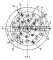
- Fig. 2 a plan view of the inventive device according to Fig. 1 .
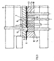
- Fig. 3 a section through the device according to the invention in the processing stage "cutting" at top dead center according to the inventive method
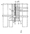
- Fig. 4 a section through the device according to the invention in the processing stage "embossing" at top dead center according to the inventive method
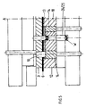
- Fig. 5 a section through the device according to the invention in the processing stage "ejection" at top dead center according to the inventive method.
- the Fig. 1 shows the basic structure of the device according to the invention for producing a finely cut and formed workpiece W.
- the device according to the invention has an upper part 1 and lower part 2.
- the upper part 1 of the device according to the invention includes a guide plate 3 with ring point 4, a punch 5 for punching a tape strip 6, a cutting punch 7 for cutting a perforated blank 8 from the tape strip 6, an embossing die 9 (see Figure 4 ) for performing a stamping operation on the cut blank 8 and at least two locking bolts 10.
- the active elements punch 5, cutting punch 7 and stamp 9 are guided in the guide plate 3. Their respective working direction is perpendicular to the tape strip 6.
- the two locking bolts 10 are disposed near the outer edge of the guide plate 3 and are diametrically opposite.
- the lower part 3 is formed from a socket 12, a disc-shaped cutting plate 13 with guide element 14, a waste channel 15, an ejector 16, an embossing boss 17 and a central bearing pin 18 which is fixed on the lower pressure plate 19.
- Cutting plate 13 and guide member 14 form a common component which is rotatable.
- corresponding cutting openings 20 are provided, which are associated with the active elements 5, 7 and 8 respectively.
- the cutting plate 13 supports centrally with its guide element 14.
- the guide member 14 is supported on its outer periphery of the socket 12, wherein in the plane E between the guide surfaces of the socket 12 and guide member 14, an unillustrated drive element acts, such as a stepper motor for generating the required drive torque for rotating the cutting plate 13 to their located on the axis of the journal 18 virtual axis A.
- an unillustrated drive element acts, such as a stepper motor for generating the required drive torque for rotating the cutting plate 13 to their located on the axis of the journal 18 virtual axis A.
- a lower under hydraulic pressure pressure pin 21 acts, with the aid of the cutting plate 13 together with its guide member 14 can perform a defined lifting movement in the direction perpendicular to the tape strip 6.
- the ejector 16 as a counter-holder for the cutting punch 7 is supported by a further under pressure hydraulic pressure pin 22.
- the disc-shaped cutting plate 13 In the disc-shaped cutting plate 13 are near its outer periphery a plurality of bolt openings 23 which are diametrically opposed. In closed delivery of upper and lower part 1 and 2, the two diametrically opposed locking bolts 10 each engage in a latch opening 23.
- the bolt axis openings 23 are distributed along the circumference of the cutting plate 13 so that upon engagement of the locking bolt 10, the corresponding active elements of the upper and lower part 1 and 2 together an active pair , ie each can form a processing stage.
- the tape strip 6 is in the closed position of Clamped upper and lower part between the guide plate 2 and cutting plate 13 and the ring prong 4 already penetrated into the tape strip 6.
- the punch 5 and the corresponding cutting opening 20 of the cutting plate 13, cutting punch 7 in the upper part 1 and ejector 16 in the lower part 2 and die 9 in the upper part 1 and refgeamboss 18 in the lower part 2 form corresponding pairs of action, as in below Fig. 2 is described in more detail, lie on a common base circle GK, which has the virtual axis A to the center.
- the Fig. 2 shows the device according to the invention in plan view, which illustrates the sequence of the method according to the invention.
- the blank 8 possibly also an inner mold is cut into the cutting opening 20 of the cutting plate 13 from the Generale Research T1 of the tape strip 6 and not ejected.
- the blank 8 remains in the cutting opening 20.
- the cutting plate 13 including guide member 14 is lifted by the hydraulically actuated pressure pin 21 and rotated with the blank 8 located in the cutting opening 20 in the next following working position.
- the rotation is in the clockwise direction to the rear of the device.
- the upper and lower parts 1 and 2 are closed, wherein the locking bolts 10 engage in the corresponding locking holes 23 of the cutting plate 13.
- the cutting plate 13 is now through the Lock bolt 10 is locked and it can on the blank 8, the next working operation, such as embossing or ejecting the slugs 26 in a channel 15 (see also Fig. 1 ).
- the cutting plate 13 is in turn raised with the blank 8 remaining in the cutting opening 20 when opening the upper and lower part and rotated until the next following working position (processing stage) is reached.
- the cutting plate 13 is locked as described in the second step and closed upper and lower parts.
- the corresponding work operation is carried out, whereby the work steps repeat until the machining of the part is completed.
- the finished workpiece is ejected from the cutting opening 20 of the cutting plate 13 in a channel 25 and removed for example by blowing out of the interior of the upper and lower part.
- the released cutting opening 20 in the cutting plate 13 reaches the working position in the part T2 row of the tape strip 6, so that a reworking cycle in the clockwise direction on the front of the device can be carried out.
- the individual pairs of action can be on concentrically arranged base circles GK, each having from the virtual axis of rotation A of the cutting plate 13 different radii R, so that several processing operations can be performed simultaneously.
- Each processing cycle is a channel 25 for the removal of the finished workpieces to the outside.
- the discharge direction AR of the finished parts can vary according to the number of active pairs (processing stages).
- the angles ⁇ can therefore vary with respect to the feeding direction of the tape strip 6.
- the channel 24 for the removal of the Abfallbutzen runs perpendicular to the feed direction of the tape strip 6 and is thus completely separated from the removal of the finished parts, so that corresponding disturbances are excluded by remaining remaining in the tool room slug remnants.
- the Fig. 3 to 5 illustrate the steps cutting, embossing and ejection.
- Upper and lower part 1 and 2 is closed and the tape strip 6 clamped between the guide plate 3 and socket 13.
- the locking bolt 10 engages in the latch opening 23.
- the cutting plate 13 is locked.
- the punch 5 and the punch 7 have cut corresponding parts in the working opening 20 of the cutting plate 13.
- the Fig. 4 shows the work embossing.
- Upper part 1 and lower part 2 of the device according to the invention is closed and the cutting plate 13 is locked by the locking bolt 10.
- the embossing stamp 9 and embossing boss 17 are in working position.
- Fig. 5 the part output of finished fine cut and formed workpieces is shown.
- a finished part is ejected and can be discharged, for example by blowing.
Landscapes
- Engineering & Computer Science (AREA)
- Mechanical Engineering (AREA)
- Press Drives And Press Lines (AREA)
- Punching Or Piercing (AREA)
- Turning (AREA)
- Auxiliary Devices For Machine Tools (AREA)
- Perforating, Stamping-Out Or Severing By Means Other Than Cutting (AREA)
- Mounting, Exchange, And Manufacturing Of Dies (AREA)
Priority Applications (14)
| Application Number | Priority Date | Filing Date | Title |
|---|---|---|---|
| PT07018046T PT2036629E (pt) | 2007-09-14 | 2007-09-14 | Processo e dispositivo para corte de precisão e conformação de uma peça de obra |
| EP07018046A EP2036629B1 (de) | 2007-09-14 | 2007-09-14 | Verfahren und Vorrichtung zum Feinschneidern und Umformen eines Werkstücks |
| DK07018046.8T DK2036629T3 (da) | 2007-09-14 | 2007-09-14 | Fremgangsmåde og indretning til finstansning og omformning af et arbejdsemne |
| AT07018046T ATE471776T1 (de) | 2007-09-14 | 2007-09-14 | Verfahren und vorrichtung zum feinschneidern und umformen eines werkstücks |
| PL07018046T PL2036629T3 (pl) | 2007-09-14 | 2007-09-14 | Sposób i urządzenie do gładkiego wykrawania i obróbki plastycznej przedmiotów |
| DE502007004202T DE502007004202D1 (de) | 2007-09-14 | 2007-09-14 | Verfahren und Vorrichtung zum Feinschneidern und Umformen eines Werkstücks |
| SI200730318T SI2036629T1 (sl) | 2007-09-14 | 2007-09-14 | Postopek in naprava za fino odrezavanje in preoblikovanje obdelovanca |
| ES07018046T ES2346153T3 (es) | 2007-09-14 | 2007-09-14 | Procedimiento y dispositivo para cortar con precision y conformar una pieza. |
| MX2008011611A MX2008011611A (es) | 2007-09-14 | 2008-09-10 | Metodo y dispositivo para el corte de precision y deformacion de una pieza de trabajo. |
| CA2639502A CA2639502C (en) | 2007-09-14 | 2008-09-11 | Method and device for fine blanking and forming a workpiece |
| KR20080090395A KR101495356B1 (ko) | 2007-09-14 | 2008-09-12 | 작업편을 정밀 블랭킹 하고 성형하는 장치 및 방법 |
| JP2008234890A JP2009066663A (ja) | 2007-09-14 | 2008-09-12 | 工作物の精密打ち抜きおよび変形方法と装置 |
| US12/283,676 US8132441B2 (en) | 2007-09-14 | 2008-09-15 | Method and device for fine blanking and forming a workpiece |
| CN2008102135811A CN101386044B (zh) | 2007-09-14 | 2008-09-16 | 用于精密冲裁和成型工件的方法和装置 |
Applications Claiming Priority (1)
| Application Number | Priority Date | Filing Date | Title |
|---|---|---|---|
| EP07018046A EP2036629B1 (de) | 2007-09-14 | 2007-09-14 | Verfahren und Vorrichtung zum Feinschneidern und Umformen eines Werkstücks |
Publications (2)
| Publication Number | Publication Date |
|---|---|
| EP2036629A1 EP2036629A1 (de) | 2009-03-18 |
| EP2036629B1 true EP2036629B1 (de) | 2010-06-23 |
Family
ID=38974657
Family Applications (1)
| Application Number | Title | Priority Date | Filing Date |
|---|---|---|---|
| EP07018046A Active EP2036629B1 (de) | 2007-09-14 | 2007-09-14 | Verfahren und Vorrichtung zum Feinschneidern und Umformen eines Werkstücks |
Country Status (14)
| Country | Link |
|---|---|
| US (1) | US8132441B2 (pl) |
| EP (1) | EP2036629B1 (pl) |
| JP (1) | JP2009066663A (pl) |
| KR (1) | KR101495356B1 (pl) |
| CN (1) | CN101386044B (pl) |
| AT (1) | ATE471776T1 (pl) |
| CA (1) | CA2639502C (pl) |
| DE (1) | DE502007004202D1 (pl) |
| DK (1) | DK2036629T3 (pl) |
| ES (1) | ES2346153T3 (pl) |
| MX (1) | MX2008011611A (pl) |
| PL (1) | PL2036629T3 (pl) |
| PT (1) | PT2036629E (pl) |
| SI (1) | SI2036629T1 (pl) |
Cited By (1)
| Publication number | Priority date | Publication date | Assignee | Title |
|---|---|---|---|---|
| EP2842654A1 (de) | 2013-08-26 | 2015-03-04 | Feintool International Holding AG | Vorrichtung und Verfahren zum Transfer von Werkstücken in und aus einem Werkzeug |
Families Citing this family (34)
| Publication number | Priority date | Publication date | Assignee | Title |
|---|---|---|---|---|
| EP2357048B1 (de) * | 2010-02-10 | 2013-06-05 | Feintool Intellectual Property AG | Verfahren und Vorrichtung zum Beeinflussen der Schnitt- und Funktionsfläche an feingeschnittenen Fertigteilen |
| EP2420977B1 (de) * | 2010-08-17 | 2013-04-24 | Feintool Intellectual Property AG | Verfahren zur Voraussage bzw. Ermittlung des Einzugs an einem Stanzteil |
| TW201318726A (zh) * | 2011-11-01 | 2013-05-16 | Chen Shu Zi | 薄形墊片沖壓成型裝置 |
| EP2608299B1 (de) * | 2011-12-22 | 2014-04-09 | Feintool Intellectual Property AG | Verfahren und Vorrichtung zum Herstellen von metallischen Bipolarplatten |
| CN104959447B (zh) * | 2015-07-14 | 2017-03-01 | 武汉理工大学 | 一种偏载主动平衡精冲模具结构 |
| DE102015115647B4 (de) * | 2015-09-16 | 2019-01-24 | Schuler Pressen Gmbh | Transportvorrichtung zum Transportieren von Münzrohlingen und Verfahren zur Herstellung einer Münze |
| US10456821B2 (en) | 2015-10-14 | 2019-10-29 | Magna Powertrain Inc. | Fine blanking cam die |
| CN105598255B (zh) * | 2016-03-14 | 2018-01-23 | 苏州友尼可紧固件有限公司 | 垫片冲压模具 |
| CN106475453A (zh) * | 2016-11-15 | 2017-03-08 | 安徽江淮汽车集团股份有限公司 | 带废料收集功能的落料冲孔模 |
| CN106734501A (zh) * | 2016-11-25 | 2017-05-31 | 安特(苏州)精密机械有限公司 | 一种高光亮高精密v型齿配件冲裁工艺 |
| CN108160816B (zh) * | 2018-02-28 | 2023-06-30 | 唐山华商金属制品股份有限公司 | 生产拉片用冲床 |
| CN108555061A (zh) * | 2018-06-23 | 2018-09-21 | 东莞理工学院 | 一种能够健康维护的压平切块收集一体机 |
| CN110666032A (zh) * | 2018-07-03 | 2020-01-10 | 温州巨丰模架有限公司 | 一种冲压模具 |
| CN109108149A (zh) * | 2018-09-12 | 2019-01-01 | 成都众凯汽车零部件制造有限公司 | 一种汽车板材打孔工装 |
| CN109290441A (zh) * | 2018-11-21 | 2019-02-01 | 海南宇龙汽车部件有限公司 | 一种汽车后门锁加强板连续冲压模 |
| CN109702084A (zh) * | 2019-03-04 | 2019-05-03 | 山东金博利达精密机械有限公司 | 一种多维多工位液压转塔冲组合设备 |
| DE102019125690B3 (de) * | 2019-09-24 | 2020-08-27 | Meteor Umformtechnik Gmbh & Co. Kg | Vorrichtung zum Feinschneiden oder Normalstanzen von Rohlingen aus einem Metallband sowie zum mehrstufigen Bearbeiten der Rohlinge mittels Schneid- und Bearbeitungswerkzeugen |
| CN110756656B (zh) * | 2019-10-17 | 2024-09-10 | 珠海格力精密模具有限公司 | 连续模冲裁组件及模内出料结构和连续模 |
| CN110976622A (zh) * | 2019-11-14 | 2020-04-10 | 四川正梁机械有限公司 | 一种汽车底盘上下板落料模具 |
| KR102349396B1 (ko) * | 2020-02-12 | 2022-01-07 | 전나래 | 다양한 규격의 그레이팅을 하나의 프레스 금형으로 제조하는 방법 및, 이 제조방법으로 제조된 그레이팅 |
| CN112091091B (zh) * | 2020-07-29 | 2022-06-28 | 湖北襄整整流器有限公司 | 一种用于制作整流管的压力机及其使用方法 |
| CN112517711B (zh) * | 2020-11-02 | 2022-09-16 | 重庆方智电子科技有限公司 | 一种用于连接片加工的冲压装置 |
| CN112517783A (zh) * | 2020-11-06 | 2021-03-19 | 江门市安诺特炊具制造有限公司 | 锅具自动生产线 |
| DE102021101969B3 (de) * | 2021-01-28 | 2022-02-10 | Kokinetics Gmbh | Feinschneid-Verfahren zur Herstellung einer Sitzversteller-Schiene |
| CN113020497B (zh) * | 2021-03-09 | 2022-11-11 | 江苏大浪电气有限公司 | 一种密集型母线的生产设备 |
| CN113458355A (zh) * | 2021-07-02 | 2021-10-01 | 江苏星火特钢有限公司 | 不锈钢材料加工设备台 |
| CN113441608A (zh) * | 2021-07-14 | 2021-09-28 | 无锡艾赛特科技有限公司 | 一种旋转换料的汽车零部件冲孔装置 |
| CN115178642B (zh) * | 2022-08-12 | 2024-08-02 | 佛山市万堃金属材料有限公司 | 一种建筑铝膜板加工成型装置及成型方法 |
| CN115990648B (zh) * | 2023-01-04 | 2026-03-03 | 东方电气集团东方电机有限公司 | 一种冲模卸料板锁止机构及冲模工装 |
| CN117175870B (zh) * | 2023-11-01 | 2023-12-29 | 佛山登奇伺服科技有限公司 | 一种电机定转子冲片生产的定心装置 |
| CN117772913B (zh) * | 2024-02-27 | 2024-04-19 | 深圳市安盛模具有限公司 | 一种快速脱模装置及其脱模方法 |
| CN117960883B (zh) * | 2024-03-29 | 2024-06-11 | 德州鲁川汽车配件制造有限公司 | 一种用于汽车零件加工的冲压装置 |
| CN118650060B (zh) * | 2024-08-16 | 2024-11-01 | 舒华体育股份有限公司 | 一种健身器材加工冲压模具及其方法 |
| CN119458476B (zh) * | 2025-01-16 | 2025-06-03 | 天津市洁雅馨橡塑制品有限公司 | 一种口腔喷头用复合喷管制备方法、设备及其制备的复合喷管 |
Family Cites Families (10)
| Publication number | Priority date | Publication date | Assignee | Title |
|---|---|---|---|---|
| US1892168A (en) * | 1928-12-04 | 1932-12-27 | Dial Engineering Corp | Dial die machine |
| CH471647A (de) * | 1967-03-29 | 1969-04-30 | Feintool Ag | Stanzpresswerkzeug |
| DE2165224C3 (de) | 1971-12-29 | 1974-07-18 | Iwk-Pressen Gmbh, 3503 Lohfelden | Stanzvorrichtung zur Anwendung in einer Stufenpresse |
| US3831426A (en) * | 1972-09-29 | 1974-08-27 | R Hakner | Progressive stamping device having work stations in a curvilinear path |
| US3848452A (en) * | 1973-03-20 | 1974-11-19 | Dayton Progress Corp | Die apparatus |
| JPS6092023A (ja) * | 1983-09-30 | 1985-05-23 | Mitsui Haitetsuku:Kk | 積層鉄芯製造用順送り金型装置 |
| CN2075560U (zh) * | 1990-10-08 | 1991-04-24 | 天津手表厂 | 小型多工位级进模 |
| DE4409658A1 (de) * | 1994-03-21 | 1995-09-28 | Pressta Eisele Gmbh | Werkzeugkombination für Stanzmaschinen |
| CN2459112Y (zh) * | 2000-09-29 | 2001-11-14 | 长春汽车材料研究所 | 汽车转向轴端管成型模具 |
| CN2582777Y (zh) * | 2002-10-24 | 2003-10-29 | 武汉市工程科学技术研究院光学研究所 | 用于板材冲压的偏心式多模错位换模装置 |
-
2007
- 2007-09-14 DK DK07018046.8T patent/DK2036629T3/da active
- 2007-09-14 AT AT07018046T patent/ATE471776T1/de active
- 2007-09-14 PT PT07018046T patent/PT2036629E/pt unknown
- 2007-09-14 EP EP07018046A patent/EP2036629B1/de active Active
- 2007-09-14 ES ES07018046T patent/ES2346153T3/es active Active
- 2007-09-14 PL PL07018046T patent/PL2036629T3/pl unknown
- 2007-09-14 SI SI200730318T patent/SI2036629T1/sl unknown
- 2007-09-14 DE DE502007004202T patent/DE502007004202D1/de active Active
-
2008
- 2008-09-10 MX MX2008011611A patent/MX2008011611A/es active IP Right Grant
- 2008-09-11 CA CA2639502A patent/CA2639502C/en active Active
- 2008-09-12 JP JP2008234890A patent/JP2009066663A/ja not_active Withdrawn
- 2008-09-12 KR KR20080090395A patent/KR101495356B1/ko active Active
- 2008-09-15 US US12/283,676 patent/US8132441B2/en active Active
- 2008-09-16 CN CN2008102135811A patent/CN101386044B/zh active Active
Cited By (1)
| Publication number | Priority date | Publication date | Assignee | Title |
|---|---|---|---|---|
| EP2842654A1 (de) | 2013-08-26 | 2015-03-04 | Feintool International Holding AG | Vorrichtung und Verfahren zum Transfer von Werkstücken in und aus einem Werkzeug |
Also Published As
| Publication number | Publication date |
|---|---|
| DE502007004202D1 (de) | 2010-08-05 |
| EP2036629A1 (de) | 2009-03-18 |
| PT2036629E (pt) | 2010-08-20 |
| US20090090157A1 (en) | 2009-04-09 |
| DK2036629T3 (da) | 2010-10-25 |
| MX2008011611A (es) | 2009-04-15 |
| CA2639502A1 (en) | 2009-03-14 |
| PL2036629T3 (pl) | 2010-11-30 |
| KR20090028471A (ko) | 2009-03-18 |
| CN101386044A (zh) | 2009-03-18 |
| JP2009066663A (ja) | 2009-04-02 |
| SI2036629T1 (sl) | 2010-09-30 |
| ATE471776T1 (de) | 2010-07-15 |
| ES2346153T3 (es) | 2010-10-11 |
| KR101495356B1 (ko) | 2015-02-24 |
| CA2639502C (en) | 2017-01-03 |
| US8132441B2 (en) | 2012-03-13 |
| CN101386044B (zh) | 2012-11-21 |
Similar Documents
| Publication | Publication Date | Title |
|---|---|---|
| EP2036629B1 (de) | Verfahren und Vorrichtung zum Feinschneidern und Umformen eines Werkstücks | |
| DE69321728T2 (de) | Zweistufiger matritzensatz | |
| DE3931320C1 (pl) | ||
| EP0183648B1 (de) | Presse zum Bearbeiten von Werkstücken aus Metall | |
| EP2233221A2 (de) | Stanzvorrichtung für eine Folgeschnitt-Stanzmaschine von Metall-Stanzteilen | |
| DE69228770T2 (de) | Index-Vorschubsystem | |
| DE4128194A1 (de) | Vorrichtung zum automatischen herstellen von blechteilen | |
| EP2335841B1 (de) | Verfahren zum Herstellen von Biegeteilen und Werkzeug hierfür | |
| DE102015116974A1 (de) | Umformvorrichtung, insbesondere Spindelpresse und Verfahren zur umformenden Bearbeitung von Werkstücken | |
| DE3116765C1 (de) | Werkzeug zum Herstellen von Senkloechern oder Passloechern in einem Blech auf einer Stanzmaschine | |
| DE102008006864A1 (de) | Verfahren und Vorrichtung zur Lochung eines Werkstücks | |
| WO1985001896A1 (fr) | Poinçonneuse et jeu d'outils pour poinçonneuses | |
| DE3440809A1 (de) | Verfahren und vorrichtung zum verbinden von aufeinanderliegenden blechen durch stanznocken | |
| DE29911152U1 (de) | Werkzeugvorrichtung zur spanenden Bearbeitung tafelförmiger Werkstücke | |
| DE1937818A1 (de) | Verfahren und Vorrichtung zum Ausstanzen sechseckiger Rohlinge | |
| EP3797893B1 (de) | Vorrichtung zum feinschneiden/normalstanzen von rohlingen aus einem metallband sowie zum mehrstufigen bearbeiten der rohlinge mittels schneid- und bearbeitungswerkzeugen | |
| EP0811438A2 (de) | Trenn- und Ausklinkvorrichtung für perforierte Bleche | |
| DE102006045477A1 (de) | Arbeitsstation für eine Tiefziehmaschine | |
| DE102006001389A1 (de) | Umformwerkzeug für eine Stanzmaschine | |
| EP1345715B1 (de) | Schmiedepresse mit stellvorrichtung auf matrizenseite | |
| EP1632297B1 (de) | Verfahren und Werkzeug zum Stanzen und/oder Formen | |
| DE69316573T2 (de) | Werkzeug zum Formen von Dosendeckel unterschiedlicher Durchmesser | |
| DE2258647A1 (de) | Presse mit zwei um die eine bzw. andere von zwei parallelen drehachsen synchron rotierenden werkzeugtraegern | |
| DE29905738U1 (de) | Stanzvorrichtung | |
| DE69601753T2 (de) | Matrizenbaugruppe für verschiedene Werkstückarten |
Legal Events
| Date | Code | Title | Description |
|---|---|---|---|
| PUAI | Public reference made under article 153(3) epc to a published international application that has entered the european phase |
Free format text: ORIGINAL CODE: 0009012 |
|
| AK | Designated contracting states |
Kind code of ref document: A1 Designated state(s): AT BE BG CH CY CZ DE DK EE ES FI FR GB GR HU IE IS IT LI LT LU LV MC MT NL PL PT RO SE SI SK TR |
|
| AX | Request for extension of the european patent |
Extension state: AL BA HR MK RS |
|
| 17P | Request for examination filed |
Effective date: 20090806 |
|
| AKX | Designation fees paid |
Designated state(s): AT BE BG CH CY CZ DE DK EE ES FI FR GB GR HU IE IS IT LI LT LU LV MC MT NL PL PT RO SE SI SK TR |
|
| GRAP | Despatch of communication of intention to grant a patent |
Free format text: ORIGINAL CODE: EPIDOSNIGR1 |
|
| GRAS | Grant fee paid |
Free format text: ORIGINAL CODE: EPIDOSNIGR3 |
|
| GRAA | (expected) grant |
Free format text: ORIGINAL CODE: 0009210 |
|
| AK | Designated contracting states |
Kind code of ref document: B1 Designated state(s): AT BE BG CH CY CZ DE DK EE ES FI FR GB GR HU IE IS IT LI LT LU LV MC MT NL PL PT RO SE SI SK TR |
|
| REG | Reference to a national code |
Ref country code: CH Ref legal event code: EP |
|
| REG | Reference to a national code |
Ref country code: CH Ref legal event code: NV Representative=s name: BOVARD AG PATENTANWAELTE |
|
| REG | Reference to a national code |
Ref country code: IE Ref legal event code: FG4D Free format text: LANGUAGE OF EP DOCUMENT: GERMAN |
|
| REF | Corresponds to: |
Ref document number: 502007004202 Country of ref document: DE Date of ref document: 20100805 Kind code of ref document: P |
|
| REG | Reference to a national code |
Ref country code: RO Ref legal event code: EPE |
|
| REG | Reference to a national code |
Ref country code: PT Ref legal event code: SC4A Free format text: AVAILABILITY OF NATIONAL TRANSLATION Effective date: 20100813 |
|
| REG | Reference to a national code |
Ref country code: GR Ref legal event code: EP Ref document number: 20100401782 Country of ref document: GR |
|
| REG | Reference to a national code |
Ref country code: NL Ref legal event code: T3 |
|
| REG | Reference to a national code |
Ref country code: ES Ref legal event code: FG2A Ref document number: 2346153 Country of ref document: ES Kind code of ref document: T3 |
|
| REG | Reference to a national code |
Ref country code: SE Ref legal event code: TRGR |
|
| REG | Reference to a national code |
Ref country code: DK Ref legal event code: T3 |
|
| PG25 | Lapsed in a contracting state [announced via postgrant information from national office to epo] |
Ref country code: LT Free format text: LAPSE BECAUSE OF FAILURE TO SUBMIT A TRANSLATION OF THE DESCRIPTION OR TO PAY THE FEE WITHIN THE PRESCRIBED TIME-LIMIT Effective date: 20100623 |
|
| PGFP | Annual fee paid to national office [announced via postgrant information from national office to epo] |
Ref country code: ES Payment date: 20100827 Year of fee payment: 4 Ref country code: NL Payment date: 20100827 Year of fee payment: 4 Ref country code: RO Payment date: 20100818 Year of fee payment: 4 |
|
| LTIE | Lt: invalidation of european patent or patent extension |
Effective date: 20100623 |
|
| PG25 | Lapsed in a contracting state [announced via postgrant information from national office to epo] |
Ref country code: FI Free format text: LAPSE BECAUSE OF FAILURE TO SUBMIT A TRANSLATION OF THE DESCRIPTION OR TO PAY THE FEE WITHIN THE PRESCRIBED TIME-LIMIT Effective date: 20100623 Ref country code: LV Free format text: LAPSE BECAUSE OF FAILURE TO SUBMIT A TRANSLATION OF THE DESCRIPTION OR TO PAY THE FEE WITHIN THE PRESCRIBED TIME-LIMIT Effective date: 20100623 |
|
| PGFP | Annual fee paid to national office [announced via postgrant information from national office to epo] |
Ref country code: CZ Payment date: 20100818 Year of fee payment: 4 Ref country code: FR Payment date: 20100819 Year of fee payment: 4 Ref country code: SE Payment date: 20100927 Year of fee payment: 4 Ref country code: SI Payment date: 20100903 Year of fee payment: 4 |
|
| REG | Reference to a national code |
Ref country code: PL Ref legal event code: T3 |
|
| REG | Reference to a national code |
Ref country code: SK Ref legal event code: T3 Ref document number: E 7923 Country of ref document: SK |
|
| PGFP | Annual fee paid to national office [announced via postgrant information from national office to epo] |
Ref country code: GR Payment date: 20100830 Year of fee payment: 4 |
|
| REG | Reference to a national code |
Ref country code: HU Ref legal event code: AG4A Ref document number: E008876 Country of ref document: HU |
|
| PG25 | Lapsed in a contracting state [announced via postgrant information from national office to epo] |
Ref country code: EE Free format text: LAPSE BECAUSE OF FAILURE TO SUBMIT A TRANSLATION OF THE DESCRIPTION OR TO PAY THE FEE WITHIN THE PRESCRIBED TIME-LIMIT Effective date: 20100623 |
|
| PGFP | Annual fee paid to national office [announced via postgrant information from national office to epo] |
Ref country code: DK Payment date: 20100922 Year of fee payment: 4 Ref country code: PT Payment date: 20100831 Year of fee payment: 4 |
|
| REG | Reference to a national code |
Ref country code: IE Ref legal event code: FD4D |
|
| PG25 | Lapsed in a contracting state [announced via postgrant information from national office to epo] |
Ref country code: IS Free format text: LAPSE BECAUSE OF FAILURE TO SUBMIT A TRANSLATION OF THE DESCRIPTION OR TO PAY THE FEE WITHIN THE PRESCRIBED TIME-LIMIT Effective date: 20101023 Ref country code: CY Free format text: LAPSE BECAUSE OF FAILURE TO SUBMIT A TRANSLATION OF THE DESCRIPTION OR TO PAY THE FEE WITHIN THE PRESCRIBED TIME-LIMIT Effective date: 20100623 |
|
| PGFP | Annual fee paid to national office [announced via postgrant information from national office to epo] |
Ref country code: BE Payment date: 20100812 Year of fee payment: 4 Ref country code: HU Payment date: 20100907 Year of fee payment: 4 Ref country code: PL Payment date: 20100831 Year of fee payment: 4 Ref country code: SK Payment date: 20100818 Year of fee payment: 4 |
|
| REG | Reference to a national code |
Ref country code: CH Ref legal event code: PFA Owner name: FEINTOOL INTELLECTUAL PROPERTY AG Free format text: FEINTOOL INTELLECTUAL PROPERTY AG#INDUSTRIERING 8#3250 LYSS (CH) -TRANSFER TO- FEINTOOL INTELLECTUAL PROPERTY AG#INDUSTRIERING 8#3250 LYSS (CH) |
|
| PG25 | Lapsed in a contracting state [announced via postgrant information from national office to epo] |
Ref country code: MC Free format text: LAPSE BECAUSE OF NON-PAYMENT OF DUE FEES Effective date: 20100930 Ref country code: IE Free format text: LAPSE BECAUSE OF FAILURE TO SUBMIT A TRANSLATION OF THE DESCRIPTION OR TO PAY THE FEE WITHIN THE PRESCRIBED TIME-LIMIT Effective date: 20100623 |
|
| PLBE | No opposition filed within time limit |
Free format text: ORIGINAL CODE: 0009261 |
|
| STAA | Information on the status of an ep patent application or granted ep patent |
Free format text: STATUS: NO OPPOSITION FILED WITHIN TIME LIMIT |
|
| 26N | No opposition filed |
Effective date: 20110324 |
|
| REG | Reference to a national code |
Ref country code: DE Ref legal event code: R097 Ref document number: 502007004202 Country of ref document: DE Effective date: 20110323 |
|
| PGFP | Annual fee paid to national office [announced via postgrant information from national office to epo] |
Ref country code: BG Payment date: 20100902 Year of fee payment: 4 |
|
| PG25 | Lapsed in a contracting state [announced via postgrant information from national office to epo] |
Ref country code: MT Free format text: LAPSE BECAUSE OF FAILURE TO SUBMIT A TRANSLATION OF THE DESCRIPTION OR TO PAY THE FEE WITHIN THE PRESCRIBED TIME-LIMIT Effective date: 20100623 |
|
| REG | Reference to a national code |
Ref country code: PT Ref legal event code: MM4A Free format text: LAPSE DUE TO NON-PAYMENT OF FEES Effective date: 20120314 |
|
| BERE | Be: lapsed |
Owner name: FEINTOOL INTELLECTUAL PROPERTY A.G. Effective date: 20110930 |
|
| REG | Reference to a national code |
Ref country code: NL Ref legal event code: V1 Effective date: 20120401 |
|
| PG25 | Lapsed in a contracting state [announced via postgrant information from national office to epo] |
Ref country code: CZ Free format text: LAPSE BECAUSE OF NON-PAYMENT OF DUE FEES Effective date: 20110914 |
|
| REG | Reference to a national code |
Ref country code: DK Ref legal event code: EBP |
|
| GBPC | Gb: european patent ceased through non-payment of renewal fee |
Effective date: 20110914 |
|
| REG | Reference to a national code |
Ref country code: GR Ref legal event code: ML Ref document number: 20100401782 Country of ref document: GR Effective date: 20120403 |
|
| PG25 | Lapsed in a contracting state [announced via postgrant information from national office to epo] |
Ref country code: PT Free format text: LAPSE BECAUSE OF NON-PAYMENT OF DUE FEES Effective date: 20120314 |
|
| REG | Reference to a national code |
Ref country code: SI Ref legal event code: KO00 Effective date: 20120418 |
|
| REG | Reference to a national code |
Ref country code: SK Ref legal event code: MM4A Ref document number: E 7923 Country of ref document: SK Effective date: 20110914 |
|
| REG | Reference to a national code |
Ref country code: FR Ref legal event code: ST Effective date: 20120531 |
|
| PG25 | Lapsed in a contracting state [announced via postgrant information from national office to epo] |
Ref country code: BE Free format text: LAPSE BECAUSE OF NON-PAYMENT OF DUE FEES Effective date: 20110930 |
|
| REG | Reference to a national code |
Ref country code: SE Ref legal event code: EUG |
|
| PG25 | Lapsed in a contracting state [announced via postgrant information from national office to epo] |
Ref country code: SK Free format text: LAPSE BECAUSE OF NON-PAYMENT OF DUE FEES Effective date: 20110914 Ref country code: NL Free format text: LAPSE BECAUSE OF NON-PAYMENT OF DUE FEES Effective date: 20120401 Ref country code: HU Free format text: LAPSE BECAUSE OF NON-PAYMENT OF DUE FEES Effective date: 20110915 |
|
| PG25 | Lapsed in a contracting state [announced via postgrant information from national office to epo] |
Ref country code: FR Free format text: LAPSE BECAUSE OF NON-PAYMENT OF DUE FEES Effective date: 20110930 Ref country code: RO Free format text: LAPSE BECAUSE OF NON-PAYMENT OF DUE FEES Effective date: 20110914 Ref country code: GR Free format text: LAPSE BECAUSE OF NON-PAYMENT OF DUE FEES Effective date: 20120403 Ref country code: GB Free format text: LAPSE BECAUSE OF NON-PAYMENT OF DUE FEES Effective date: 20110914 |
|
| PG25 | Lapsed in a contracting state [announced via postgrant information from national office to epo] |
Ref country code: LU Free format text: LAPSE BECAUSE OF NON-PAYMENT OF DUE FEES Effective date: 20100914 |
|
| PG25 | Lapsed in a contracting state [announced via postgrant information from national office to epo] |
Ref country code: DK Free format text: LAPSE BECAUSE OF NON-PAYMENT OF DUE FEES Effective date: 20110930 Ref country code: SI Free format text: LAPSE BECAUSE OF NON-PAYMENT OF DUE FEES Effective date: 20110915 Ref country code: PL Free format text: LAPSE BECAUSE OF NON-PAYMENT OF DUE FEES Effective date: 20110914 |
|
| REG | Reference to a national code |
Ref country code: PL Ref legal event code: LAPE |
|
| REG | Reference to a national code |
Ref country code: ES Ref legal event code: FD2A Effective date: 20130417 |
|
| PG25 | Lapsed in a contracting state [announced via postgrant information from national office to epo] |
Ref country code: SE Free format text: LAPSE BECAUSE OF NON-PAYMENT OF DUE FEES Effective date: 20110915 Ref country code: ES Free format text: LAPSE BECAUSE OF NON-PAYMENT OF DUE FEES Effective date: 20110915 |
|
| PG25 | Lapsed in a contracting state [announced via postgrant information from national office to epo] |
Ref country code: BG Free format text: LAPSE BECAUSE OF NON-PAYMENT OF DUE FEES Effective date: 20110630 |
|
| PG25 | Lapsed in a contracting state [announced via postgrant information from national office to epo] |
Ref country code: TR Free format text: LAPSE BECAUSE OF FAILURE TO SUBMIT A TRANSLATION OF THE DESCRIPTION OR TO PAY THE FEE WITHIN THE PRESCRIBED TIME-LIMIT Effective date: 20100623 |
|
| REG | Reference to a national code |
Ref country code: CH Ref legal event code: PUE Owner name: FEINTOOL INTERNATIONAL HOLDING AG, CH Free format text: FORMER OWNER: FEINTOOL INTELLECTUAL PROPERTY AG, CH |
|
| REG | Reference to a national code |
Ref country code: AT Ref legal event code: MM01 Ref document number: 471776 Country of ref document: AT Kind code of ref document: T Effective date: 20120914 |
|
| PG25 | Lapsed in a contracting state [announced via postgrant information from national office to epo] |
Ref country code: AT Free format text: LAPSE BECAUSE OF NON-PAYMENT OF DUE FEES Effective date: 20120914 |
|
| REG | Reference to a national code |
Ref country code: DE Ref legal event code: R082 Ref document number: 502007004202 Country of ref document: DE Representative=s name: COHAUSZ HANNIG BORKOWSKI WISSGOTT, DE |
|
| REG | Reference to a national code |
Ref country code: DE Ref legal event code: R082 Ref document number: 502007004202 Country of ref document: DE Representative=s name: COHAUSZ HANNIG BORKOWSKI WISSGOTT, DE Effective date: 20140212 Ref country code: DE Ref legal event code: R081 Ref document number: 502007004202 Country of ref document: DE Owner name: FEINTOOL INTERNATIONAL HOLDING AG, CH Free format text: FORMER OWNER: FEINTOOL INTELLECTUAL PROPERTY AG, LYSS, CH Effective date: 20140212 |
|
| REG | Reference to a national code |
Ref country code: CH Ref legal event code: U11 Free format text: ST27 STATUS EVENT CODE: U-0-0-U10-U11 (AS PROVIDED BY THE NATIONAL OFFICE) Effective date: 20251001 |
|
| PGFP | Annual fee paid to national office [announced via postgrant information from national office to epo] |
Ref country code: DE Payment date: 20250919 Year of fee payment: 19 |
|
| PGFP | Annual fee paid to national office [announced via postgrant information from national office to epo] |
Ref country code: IT Payment date: 20250930 Year of fee payment: 19 |
|
| PGFP | Annual fee paid to national office [announced via postgrant information from national office to epo] |
Ref country code: CH Payment date: 20251001 Year of fee payment: 19 |