EP2000735A1 - Kühlsystem für einen kryogenischen Speicherbehälter und Betriebsverfahren dafür - Google Patents
Kühlsystem für einen kryogenischen Speicherbehälter und Betriebsverfahren dafür Download PDFInfo
- Publication number
- EP2000735A1 EP2000735A1 EP08251953A EP08251953A EP2000735A1 EP 2000735 A1 EP2000735 A1 EP 2000735A1 EP 08251953 A EP08251953 A EP 08251953A EP 08251953 A EP08251953 A EP 08251953A EP 2000735 A1 EP2000735 A1 EP 2000735A1
- Authority
- EP
- European Patent Office
- Prior art keywords
- coolant
- storage container
- container
- vacuum
- vacuum container
- Prior art date
- Legal status (The legal status is an assumption and is not a legal conclusion. Google has not performed a legal analysis and makes no representation as to the accuracy of the status listed.)
- Withdrawn
Links
- 238000001816 cooling Methods 0.000 title claims abstract description 134
- 238000011017 operating method Methods 0.000 title claims description 11
- 239000002826 coolant Substances 0.000 claims abstract description 233
- 239000000463 material Substances 0.000 claims description 7
- 230000008878 coupling Effects 0.000 claims description 6
- 238000010168 coupling process Methods 0.000 claims description 6
- 238000005859 coupling reaction Methods 0.000 claims description 6
- 239000001307 helium Substances 0.000 abstract description 60
- 229910052734 helium Inorganic materials 0.000 abstract description 60
- SWQJXJOGLNCZEY-UHFFFAOYSA-N helium atom Chemical compound [He] SWQJXJOGLNCZEY-UHFFFAOYSA-N 0.000 abstract description 60
- 239000007789 gas Substances 0.000 abstract description 39
- 238000001704 evaporation Methods 0.000 abstract description 15
- 230000008020 evaporation Effects 0.000 abstract description 15
- 239000007788 liquid Substances 0.000 description 28
- 230000005855 radiation Effects 0.000 description 7
- 238000005259 measurement Methods 0.000 description 6
- 239000011152 fibreglass Substances 0.000 description 5
- 230000035945 sensitivity Effects 0.000 description 5
- 229910001220 stainless steel Inorganic materials 0.000 description 5
- 239000010935 stainless steel Substances 0.000 description 5
- IJGRMHOSHXDMSA-UHFFFAOYSA-N Atomic nitrogen Chemical compound N#N IJGRMHOSHXDMSA-UHFFFAOYSA-N 0.000 description 4
- 238000000034 method Methods 0.000 description 4
- 229910052782 aluminium Inorganic materials 0.000 description 3
- XAGFODPZIPBFFR-UHFFFAOYSA-N aluminium Chemical compound [Al] XAGFODPZIPBFFR-UHFFFAOYSA-N 0.000 description 3
- 230000007423 decrease Effects 0.000 description 2
- 230000003247 decreasing effect Effects 0.000 description 2
- 230000009545 invasion Effects 0.000 description 2
- 229910052757 nitrogen Inorganic materials 0.000 description 2
- 230000008569 process Effects 0.000 description 2
- 238000004904 shortening Methods 0.000 description 2
- 125000006850 spacer group Chemical group 0.000 description 2
- RYGMFSIKBFXOCR-UHFFFAOYSA-N Copper Chemical compound [Cu] RYGMFSIKBFXOCR-UHFFFAOYSA-N 0.000 description 1
- 230000002238 attenuated effect Effects 0.000 description 1
- 238000009835 boiling Methods 0.000 description 1
- 239000004020 conductor Substances 0.000 description 1
- 229910052802 copper Inorganic materials 0.000 description 1
- 239000010949 copper Substances 0.000 description 1
- 230000000593 degrading effect Effects 0.000 description 1
- 239000011810 insulating material Substances 0.000 description 1
- 239000000696 magnetic material Substances 0.000 description 1
- 230000007246 mechanism Effects 0.000 description 1
- 239000007769 metal material Substances 0.000 description 1
- 238000012986 modification Methods 0.000 description 1
- 230000004048 modification Effects 0.000 description 1
- 229910052755 nonmetal Inorganic materials 0.000 description 1
- XLYOFNOQVPJJNP-UHFFFAOYSA-N water Substances O XLYOFNOQVPJJNP-UHFFFAOYSA-N 0.000 description 1
Images


Classifications
-
- H—ELECTRICITY
- H01—ELECTRIC ELEMENTS
- H01F—MAGNETS; INDUCTANCES; TRANSFORMERS; SELECTION OF MATERIALS FOR THEIR MAGNETIC PROPERTIES
- H01F6/00—Superconducting magnets; Superconducting coils
- H01F6/04—Cooling
-
- G—PHYSICS
- G01—MEASURING; TESTING
- G01R—MEASURING ELECTRIC VARIABLES; MEASURING MAGNETIC VARIABLES
- G01R33/00—Arrangements or instruments for measuring magnetic variables
- G01R33/20—Arrangements or instruments for measuring magnetic variables involving magnetic resonance
- G01R33/28—Details of apparatus provided for in groups G01R33/44 - G01R33/64
- G01R33/38—Systems for generation, homogenisation or stabilisation of the main or gradient magnetic field
- G01R33/3804—Additional hardware for cooling or heating of the magnet assembly, for housing a cooled or heated part of the magnet assembly or for temperature control of the magnet assembly
-
- G—PHYSICS
- G01—MEASURING; TESTING
- G01R—MEASURING ELECTRIC VARIABLES; MEASURING MAGNETIC VARIABLES
- G01R33/00—Arrangements or instruments for measuring magnetic variables
- G01R33/20—Arrangements or instruments for measuring magnetic variables involving magnetic resonance
- G01R33/28—Details of apparatus provided for in groups G01R33/44 - G01R33/64
- G01R33/38—Systems for generation, homogenisation or stabilisation of the main or gradient magnetic field
- G01R33/381—Systems for generation, homogenisation or stabilisation of the main or gradient magnetic field using electromagnets
- G01R33/3815—Systems for generation, homogenisation or stabilisation of the main or gradient magnetic field using electromagnets with superconducting coils, e.g. power supply therefor
Definitions
- the present invention relates to a system for a cryogenic storage container and its operating method, and more specifically to a cooling system for a cryogenic storage container by using a coolant such as a liquid helium for cooling at a cryogenic temperature and its operating method.
- a device requiring a high magnetic field such as an MRI and an NMR.
- a device using superconductivity is applied to measure a weak magnetic field.
- These objects to be cooled are cooled as soaked in a low temperature coolant, and normally liquid helium having a boiling point of 4.2 K (-269°C) is used as a coolant.
- Liquid helium is low in evaporation latent heat, and the evaporation latent heat of the liquid helium under an atmospheric pressure is 20.7 [kJ/kg] which is not more than 1/100 of the evaporation latent heat (2257 [kJ/kg]) of water under the atmospheric pressure, and a large amount of liquid helium evaporates by slight heat invasion. Therefore, in a cooling system using liquid helium, it is necessary to periodically supply liquid helium.
- a well-known method to suppress the heat invasion into the liquid helium stored in a cryogenic container is to provide a heat shield in a vacuum tank between a container storing liquid helium and a vacuum container, cool the heat shield down to the intermediate temperature between the room temperature of the vacuum container and the temperature of the liquid helium, and prevent the radiant heat from the vacuum container at the room temperature from directly being delivered to the liquid helium container (for example, refer to JP-A-2002-232030 and JP-A-2002-232029 ).
- the high-temperature side heat shield provided on the vacuum container side is about 77 K to 200 K
- the heat shield provided on the liquid helium storage container side is about 4.2 K to 77 K.
- the sensible heat of a helium gas evaporated from liquid helium is commonly used as a cooling source of a heat shield.
- the flow rate of the helium gas decreases, thereby degrading the performance of cooling the heat shield, and raising the heat shield cooling temperature.
- JP-A-2002-232030 there is one heat shield to shorten the distance between a storage container and a vacuum container.
- the cooling source of the heat shield is the sensible heat of the helium gas evaporated from the liquid helium. Therefore, when there is a small amount of evaporation, the temperature at which the helium gas cools the heat shield rises, and the amount of radiant heat from the heat shield increases. Without a cryogenic freezer, the heat shield temperature and the amount of evaporation of the liquid helium depend on the balance between the temperature of the heat shield and the heat shield cooling function of the evaporated helium gas.
- the heat shield can be cooled down to a lower temperature with a smaller amount of evaporation of the liquid helium, thereby reducing the amount of evaporation of the liquid helium.
- a cryogenic freezer necessarily generates a vibration although at different levels depending on the difference in the structure of a freezer and a cooling system. Therefore, it is difficult to apply it to a living body magnetic measurement and a magnet for an NMR in which a slight vibration can affect the sensitivity.
- the object of the present invention is to provide a cooling system for a cryogenic storage container which may address the problem of the vibration occurring when a heat shield is cooled using a cryogenic freezer, and an operating method for suppressing the amount of evaporation of a coolant from a cryogenic storage container.
- the present invention is a cooling system for a cryogenic storage container including: a storage container storing an object to be cooled as soaked in a coolant; a vacuum container provided around the storage container and forming a vacuum tank between the vacuum container and the storage container; a heat shield provided for the vacuum tank; a cryogenic storage container having coolant piping fixed to the heat shield; a cooling source provided with a cryogenic freezer for cooling a coolant passing through the coolant piping; and coolant transport piping coupling the cooling source to the cryogenic storage container, wherein the coolant cooled by the cryogenic freezer is delivered to the cryogenic storage container through the transport piping.
- the present invention is also a cooling system for a cryogenic storage container including:
- the present invention is also an operating method for a cooling system for a cryogenic storage container including:
- the present invention is also an operating method for a cooling system for a cryogenic storage container including:
- the heat shield provided between the storage container and the vacuum container of the cryogenic storage container has a divided structure, and the divided heat shields are coupled by a low thermal conductive material.
- a bellows unit is provided at least in a part of the third vacuum container in the coolant transport piping for coupling the cryogenic storage container to the cooling source. It is also desired to provide a bellows unit at least in a part of the third coolant piping in the coolant transport piping.
- the present invention can solve the problem of the vibration occurring when a cryogenic freezer is used, and can suppress the amount of evaporation of the liquid helium from the coolant storage container on the cryogenic storage container.
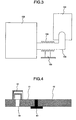
- Fig. 3 shows the rough configuration of the cooling system for a cryogenic storage container according to the present invention.
- the cooling system for a cryogenic storage container according to the present invention is configured by a storage unit 100, a cooling source 101, and a transport piping 102.
- the cooling source 101 is equipped with a cryogenic freezer not shown in the attached drawings.
- the cryogenic freezer is coupled to a compressor not shown in the attached drawings via high pressure piping.
- Using the cryogenic freezer eliminate the necessity to supply a coolant such as liquid nitrogen, liquid helium, etc.
- the coolness at or lower than the temperature of liquid nitrogen occurring in the cooling stage of the cryogenic freezer can be used.
- a bellows unit 104 is provided for a part of the transport piping 102.
- the bellows unit 104 is fixed to the floor using a support table 105 at any portion of the bellows unit 104.
- the cooling source 101 contains a cryogenic freezer for generating a vibration.
- the cryogenic freezer provides a constant vibration for the cooling source 101 to which the cryogenic freezer is fixed.
- the vibration generated by the cooling source 101 is delivered to the storage unit 100 through the transport piping 102.
- the vibration occurring in the cooling source 101 can be attenuated before reaching the storage unit 100.
- the bellows unit 104 provided for the transport piping 102, the bellows unit 104 can be fixed to the support table 105 on the floor with high rigidity at any portion of the bellows unit, thereby further reducing the vibration on the fixing unit of the bellows unit 104.
- the fixing unit between the bellows unit 104 and the support table 105 can be a high rigidity stainless steel pipe etc. However, in this case, it is desired to provide the bellows unit at either ends of the fixing unit.
- Fig. 1 is a sectional view of the storage unit of the cryogenic coolant storage container using a superconductive magnet for an NMR according to the present invention.
- the storage unit 100 is configured by a storage container 2 storing a coolant 5 and a superconductive magnet 1a as an object to be cooled, a vacuum container 3 for generating a vacuum tank 10 between the vacuum container 3 and the storage container 2, double heat shields 7 and 8 provided around the storage container 2 in the vacuum tank 10, one provided heat shield 9 between the storage container 2 and the vacuum container 3 in the vacuum tank 10, and a coolant piping 11 passing a coolant for cooling each heat shield.
- the storage unit 100 is commonly manufactured using stainless steel and aluminum. Especially since the access port 14 has the problem of the magnetic properties of the material, it is desired to use aluminum having low magnetic susceptibility.
- the heat shield 8 provided on the vacuum container 3 side at the room temperature is referred to as a high temperature shield
- the heat shield 7 provided on the storage container 2 side is referred to as a low temperature shield.
- the high temperature shield 8 receives radiation from the vacuum container 3 at the room temperature
- the low temperature shield 7 receives radiation from the high temperature shield 8.
- the storage container 2 receives radiation from the low temperature shield 7.
- the one provided heat shield 9 between the storage container 2 and the vacuum container 3 in the vacuum tank 10 receives radiation from the access port 14 at the room temperature.
- the storage container 2 receives radiation from the heat shield 9 because there is the storage container 2 inside the heat shield 9.
- the heat shields 7, 8, and 9 thermally contact the coolant piping 11 through, for example, an aluminum tape, and are cooled by heat exchange with a coolant cooled at a cryogenic temperature passing in the coolant piping 11.
- the coolant piping 11 is formed by a stainless steel pipe in a transportation region.
- the heat contact portion between the heat shields 7, 8, and 9 and the coolant piping 11 is connected by a copper pipe having high thermal conductivity and intensity.
- the piping of the heat contact portion can be stainless steel. However, it is necessary to decrease the thickness of the piping.
- the heat shield 7 provided as a double structure between the storage container 2 and the vacuum container 3 in the vacuum tank 10 is divided, and each of the divided shields is provided with a heat contact portion with the coolant piping 11.
- the division of the heat shield 7 depends on the shield temperature of the divided heat shield 7, and the shields to be cooled at the same temperature can be coupled. Since the heat shield coupled to the coupling portion (aperture) to the room temperature unit receives thermal conduction from the room temperature, the temperature rises. To reduce the high temperature portion of the heat shield, the heat shield coupled to the coupling portion to the room temperature unit is separated from another heat shield.
- Fig. 4 shows the structure for fixing the heat shield division part.
- a spacer 65 is interposed between heat shields 61 and 62 to be cooled at different temperatures.
- GFRP glass fiber reinforced plastic
- a temperature difference can be made between the heat shields 61 and 62.
- the heat shield cannot be vacuum inside. Therefore, it is necessary to provide several exhaust holes 66.
- it is effective to enhance the radiation rate on the inner surfaces of the holes, or cover the surroundings of the exhaust holes with an exhaust shield 67.
- the double heat shields 8 provided between the storage container 2 and the vacuum container 3 in the vacuum tank 10 have similar structures as the heat shield 7.
- piping is provided for cooling between the double heat shields 7 and 8 between the storage container 2 and the vacuum container 3 in the vacuum tank 10 with respect to the one provided heat shield 9 between the storage container 2 and the access port 14 in the vacuum tank 10.
- a laminated heat insuring material not shown in the attached drawings is provided between the vacuum container 3 and the high temperature shield 8 in the double heat shields provided between the storage container 2 and the vacuum container 3 in the vacuum tank 10 so that the radiant heat from the vacuum container 3 at the room temperature to the high temperature shield 8 can be reduced.
- Fig. 5 is a sectional view of the structure of the cooling source according to the present invention.
- the cooling source 101 is configured by a second vacuum container 21, a cryogenic freezer 30 fixed to the second vacuum container 21, counterflow heat exchangers 22 and 23 provided in the second vacuum container 21, a heat exchange unit 41 thermally coupled to the first cooling stage 31 of the cryogenic freezer 30, a heat exchange unit 42 thermally coupled to a second cooling stage 32 of the cryogenic freezer 30, a heat shield 24 thermally coupled to the first cooling stage 31 of the cryogenic freezer 30, and the coolant piping 11.
- a Gifford-McMahon freezer (hereinafter referred to as a GM freezer) is used as the cryogenic freezer 30.
- a GM freezer Gifford-McMahon freezer
- there is only one GM freezer used in the present embodiment there can be a plurality of freezers depending on the cooling capacity. If there is no problem with the cooling capacity, a pulse pipe freezer generating a lower vibration than the GM freezer can be applied.
- a helium gas compressed by a compressor not shown in the attached drawings is charged inside the coolant piping 11.
- the coolant piping is made of stainless steel.
- the helium gas supplied to the cooling source 101 from the compressor at the room temperature is processed in heat exchange process with the opposite helium gas when the helium gas passes through the counterflow heat exchanger 22, and is cooled down to a low temperature.
- the gas is cooled down to the same temperature as the first cooling stage 31 of the cryogenic freezer 30 by the heat exchange unit 41 thermally coupled to the first cooling stage 31 of the cryogenic freezer 30.
- it passes through the counterflow heat exchanger 23 it is processed in the heat exchange process with the opposite helium gas, there by further reducing the temperature.
- the heat exchange unit 42 thermally coupled to the second cooling stage 32 of the cryogenic freezer 30 cools down the gas to the same temperature as the second cooling stage 32 of the cryogenic freezer 30, and the gas is delivered to the storage unit 100 through coolant piping 11a provided in the transport piping 102.
- the helium gas After the temperature of the helium gas has risen by the heat exchange with the heat shield as an object to be cooled in the storage unit 100, the helium gas is fed back to the cooling source 101 through coolant piping 11b, and is used as a low temperature source of the counterflow heat exchanger 23.
- the heat exchange is performed between the gas and the opposite helium gas.
- the helium gas whose temperature has risen is delivered to the storage unit 100 through coolant piping 11c.
- the helium gas whose temperature has risen by the heat exchange with the heat shield as an object to be cooled in the storage unit 100 is fed back to the cooling source 101 through coolant piping 11d, and is used as a low temperature source of the counterflow heat exchanger 22.
- the heat exchange is performed with the opposite helium gas, and the helium gas whose temperature has risen to the room temperature is returned to the compressor not shown in the attached drawings.
- the heat shield 24 thermally coupled to the first cooling stage 31 of the cryogenic freezer 30 reduces the radiation to the second cooling stage 32 of the cryogenic freezer 30 and the counterflow heat exchanger 23.
- a laminated heat insulating material not shown in the attached drawings is provided to reduce the radiant heat from the vacuum container 21 to the heat shield 24.
- the vibration occurring from the cryogenic freezer 30 is reduced by the attenuating mechanism not shown in the attached drawings provided for the second vacuum container 21.
- the vibration passing through the coolant piping 11 is decreased in the bellows unit not shown in the attached drawings provided at a part of the coolant piping 11.
- a part of the vacuum container of the transport piping 102 has a bellows structure not shown in the attached drawings, and reduces the vibration passing through the vacuum container.
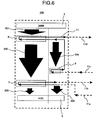
- Fig. 6 shows a cooling path of the heat shield provided in the storage unit 100 using a coolant cooled at a cryogenic temperature by the cooling source 101.
- the helium gas cooled down to the same temperature as the second cooling stage 32 of the cryogenic freezer 30 is delivered to the storage unit 100 through the coolant piping 11a, and the low temperature shield 7 in the double heat shields between the storage container 2 and the vacuum container 3 in the vacuum tank 10 is cooled. Since there is the high temperature shield 8 around the low temperature shield 7, radiant heat 202 received by the low temperature shield 7 from the high temperature shield 8 is low, and the rise of the temperature of the helium gas passing through the coolant piping 11 is low.
- the helium gas whose temperature has risen by the heat exchange with the low temperature shield 7 is temporarily delivered to the cooling source 101 through the coolant piping lib, and is used as a low temperature source of the counterflow heat exchanger 23.
- the heat exchange is performed between the gas and the opposite helium gas, and the helium gas whose temperature has risen is delivered again to the storage unit 100 through the coolant piping 11c, and the one provided heat shield 9 between the storage container 2 and the vacuum container 3 in the vacuum tank 10 is cooled.
- the heat shield 9 receives radiant heat 204 from the vacuum container 3 at the room temperature, the temperature of the helium gas as a coolant rises.
- the high temperature shield 8 in the two provided heat shields between the storage container 2 and the vacuum container 3 in the vacuum tank 10 is cooled. Since the high temperature shield 8 receives radiant heat 201 from the vacuum container 3 at the room temperature, the temperature of the coolant is furthermore risen.
- the helium gas whose temperature has risen by the heat exchange with the heat shield 9 is delivered to the cooling source 101 through the coolant piping 11d, and is used as the low temperature source of the counterflow heat exchanger 22.
- the low temperature shield 7 in the double provided heat shields between the storage container 2 and the vacuum container 3 in the vacuum tank 10 is cooled down to about 4.2 K to 10 K
- the high temperature shield 8 is cooled down to about 70 K to 100 K
- the one provided heat shield 9 between the storage container 2 and the vacuum container 3 in the vacuum tank 10 is cooled down to about 25 K to 45 K.
- the storage container 2 receives radiant heat 203 from the heat shield 7, and radiant heat 205 from the heat shield 9, the amount of evaporation of the liquid helium from the storage container 2 can be suppressed because each heat shield temperature is low.
- Fig. 8 is a sectional view showing the structure of the transport piping 102.
- the transport piping 102 is configured by a third vacuum container 301 and coolant piping 302 passing a coolant inside.
- the bellows unit is used at least a part of the third vacuum container 301 configuring the transport piping 102.
- the vacuum container 3, the second vacuum container 21, and a third vacuum container 301 are coupled to one another.
- Each coolant piping provided in the vacuum container 3, the second vacuum container 21, and the third vacuum container 301 is coupled to realize the cooling path shown in Fig. 6 .
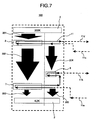
- Fig. 7 shows another example of a path for cooling a heat shield provided in the storage unit 100 using a coolant cooled at a cryogenic temperature by the cooling source 101.
- the entire configuration is the same as shown in Fig. 3 .
- the structure of the storage unit 100 is also the same as the structure shown in Fig. 1 .
- the structure of the cooling source 101 is the same as the structure shown in Fig. 5 .
- the structure of the transport piping 102 is the same as the structure shown in Fig. 8 .
- the helium gas cooled down to the same temperature as the second cooling stage 32 of the cryogenic freezer 30 by the heat exchange unit 42 thermally coupled to the second cooling stage 32 of the cryogenic freezer 30 in the cooling source 101 is delivered to the storage unit 100 through the coolant piping 11a, and cools the heat shield 7 in the two provided heat shields between the storage container 2 and the vacuum container 3 in the vacuum tank 10. Since there is the high temperature shield 8 around the low temperature shield 7, the radiant heat 202 received by the low temperature shield 7 from the high temperature shield 8 is low, and the rise of the temperature of the helium gas passing the coolant piping 11a is low.
- the helium gas whose temperature has risen by the heat exchange with the low temperature shield 7 cools the one provided heat shield 9 between the storage container 2 and the access port 14 in the vacuum tank 10. Since the heat shield 9 receives the radiant heat 204 from the access port 14 at the room temperature, the temperature of the helium gas as a coolant rises.
- the helium gas whose temperature has risen is temporarily delivered to the cooling source 101 through the coolant piping 11b, and is used as a low temperature source of the counterflow heat exchanger 23.
- the helium gas whose temperature has risen by the heat exchange with the opposite helium gas is delivered again to the storage unit 100 through the coolant piping 11c, and cools the high temperature shield 8 in the two provided heat shields between the storage container 2 and the vacuum container 3 in the vacuum tank 10. Since the high temperature shield 8 receives the radiant heat 201 from the vacuum container 3 at a room temperature, it has a large amount of received heat, and the temperature of the coolant further rises.
- the helium gas whose temperature has risen by the heat exchange with the high temperature shield 8 is delivered again to the cooling source 101 through the coolant piping 11d, and is used as a low temperature source of the counterflow heat exchanger 22.
- the low temperature shield 7 in the double provided heat shields between the storage container 2 and the vacuum container 3 in the vacuum tank 10 is cooled down to about 10 K to 15 K
- the high temperature shield 8 is cooled down to about 70 K to 100 K
- the one provided heat shield 9 between the storage container 2 and the vacuum container 3 in the vacuum tank 10 is cooled down to about 20 K to 30 K.
- the amount of radiant heat to the storage container 2 can be reduced.
- the storage container 2 receives radiant heat 203 from the low temperature shield 7, and radiant heat 205 from the heat shield 9, the amount of evaporation of the liquid helium from the storage container 2 can be suppressed because each heat shield temperature is low.
- the cooling system and its operating method of the present invention are not limited to an application to a magnet for an NMR.
- it is also applicable to a magnet for an MRI.
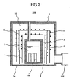
- Fig. 2 is a sectional view of the storage unit of the cryogenic storage container storing a superconductive device.
- the entire configuration of the cryogenic storage container is the same as the configuration shown in Fig. 3 .
- the structure of the cooling source is the same as the structure shown in Fig. 5 .
- the path for circulating a coolant can be any of the circulation paths shown in Figs. 5 and 6 .
- the structure of the transport piping is the same as the structure shown in Fig. 8 .
- the superconductive device refers to, for example, a superconducting quantum interference device (SQUID) for measuring a weak magnetic field.
- the SQUID is a high sensitive magnetic sensor capable of measuring a weak magnetic field of 1/1,000,000 or less of the earth's magnetic field. To realize a high sensitive measurement, it is necessary to reduce the thermal noise occurring from the SQUID itself. Therefore, liquid helium is used for cooling at a cryogenic temperature.
- the distance from a superconductive device 1b to a measurement surface 3a of the vacuum container 3 largely depends on the measurement sensitivity, and the sensitivity is greatly improved by shortening the distance.
- the storage unit 100 stores the coolant 5, and is configured by a storage container 2 storing the superconductive device 1b, the vacuum container 3 for generating the vacuum tank 10 between the vacuum container 3 and the storage container 2, the double heat shields 7 and 8 provided around the storage container 2 in the vacuum tank 10, the one provided heat shield 9 between the storage container 2 and the vacuum container 3 in the vacuum tank 10, and the coolant piping 11 passing a coolant for cooling each heat shield.
- the vacuum container 3 is connected to the vacuum container of the transport piping 102.
- the storage unit 100 is generally manufactured by a non-metal material and a non-magnetic material, and can be manufactured using, for example, a GFRP. Since an eddy-current occurring in the heat shield configuring a storage unit can affect the measurement of the superconductive device 1b, there is no coolant piping 11 around the superconductive device 1b. The joint portion between the heat shield 9 and the coolant piping 11 is provided with a sufficient distance kept to measure the superconductive device. It is common to all heat shields.
- the heat shield 9 is supported by a heat insuring support unit 15 made of a material having thermal conductivity lower than that of the heat shields 8 and 9, for example, a GFRP between the heat shield 9 and the heat shield 8.
- a heat insuring support unit 15 made of a material having thermal conductivity lower than that of the heat shields 8 and 9, for example, a GFRP between the heat shield 9 and the heat shield 8.
Landscapes
- Physics & Mathematics (AREA)
- Condensed Matter Physics & Semiconductors (AREA)
- General Physics & Mathematics (AREA)
- Engineering & Computer Science (AREA)
- Power Engineering (AREA)
- Electromagnetism (AREA)
- Containers, Films, And Cooling For Superconductive Devices (AREA)
Applications Claiming Priority (1)
| Application Number | Priority Date | Filing Date | Title |
|---|---|---|---|
| JP2007153015A JP4763656B2 (ja) | 2007-06-08 | 2007-06-08 | 極低温格納容器冷却システム及びその運用方法 |
Publications (1)
| Publication Number | Publication Date |
|---|---|
| EP2000735A1 true EP2000735A1 (de) | 2008-12-10 |
Family
ID=39760815
Family Applications (1)
| Application Number | Title | Priority Date | Filing Date |
|---|---|---|---|
| EP08251953A Withdrawn EP2000735A1 (de) | 2007-06-08 | 2008-06-05 | Kühlsystem für einen kryogenischen Speicherbehälter und Betriebsverfahren dafür |
Country Status (3)
| Country | Link |
|---|---|
| US (1) | US20080307801A1 (de) |
| EP (1) | EP2000735A1 (de) |
| JP (1) | JP4763656B2 (de) |
Families Citing this family (8)
| Publication number | Priority date | Publication date | Assignee | Title |
|---|---|---|---|---|
| EP2562489B1 (de) * | 2010-04-23 | 2020-03-04 | Sumitomo Heavy Industries, LTD. | Kühlsystem und -verfahren |
| US8809824B1 (en) | 2010-12-13 | 2014-08-19 | The Boeing Company | Cryogenically cooled radiation shield device and associated method |
| US8575580B1 (en) | 2010-12-13 | 2013-11-05 | The Boeing Company | Radiation shield device and associated method |
| US8405057B1 (en) * | 2011-04-22 | 2013-03-26 | The Boeing Company | Radiation shield device with embedded cryogen storage and associated method |
| JP6201171B2 (ja) * | 2013-06-20 | 2017-09-27 | 株式会社新領域技術研究所 | 低振動トランスファーチューブ |
| JP2021148406A (ja) * | 2020-03-23 | 2021-09-27 | 株式会社リコー | 極低温冷凍機および生体磁気計測装置 |
| JP7606433B2 (ja) * | 2021-09-16 | 2024-12-25 | 住友重機械工業株式会社 | 超伝導磁石装置および輻射シールド構造 |
| CN118031096A (zh) * | 2024-01-10 | 2024-05-14 | 南通中集能源装备有限公司 | 超低温液体储罐 |
Citations (12)
| Publication number | Priority date | Publication date | Assignee | Title |
|---|---|---|---|---|
| JPS58184775A (ja) * | 1982-04-22 | 1983-10-28 | Toshiba Corp | 超電導マグネツト用断熱容器 |
| DE4039365A1 (de) * | 1990-12-10 | 1992-06-11 | Bruker Analytische Messtechnik | Nmr-magnetsystem mit supraleitender spule in einem low-loss-kryostaten |
| US5426949A (en) | 1991-07-15 | 1995-06-27 | Hitachi, Ltd. | Vacuum vessel having a cooled member |
| US5485730A (en) * | 1994-08-10 | 1996-01-23 | General Electric Company | Remote cooling system for a superconducting magnet |
| DE19548272C1 (de) * | 1995-12-22 | 1997-05-28 | Bruker Analytische Messtechnik | Supraleitende NMR-Magnetanordnung |
| EP0797059A2 (de) * | 1996-03-18 | 1997-09-24 | Kabushiki Kaisha Toshiba | Tiefstemperaturkühlgerät und Verfahren zum Abkühlen eines Objektes auf sehr tiefe Temperaturen |
| EP0860668A2 (de) * | 1997-02-25 | 1998-08-26 | Kabushiki Kaisha Toshiba | Ein adiabatisches Gerät |
| WO2005081009A1 (en) * | 2004-02-12 | 2005-09-01 | Magnex Scientific Limited | Cryogenic cooling of superconducting magnet systems below temperature of 4 . 2 k |
| EP1574777A2 (de) * | 2004-03-13 | 2005-09-14 | Bruker BioSpin GmbH | Supraleitendes Magnetsystem mit Refrigerator |
| DE102004012452A1 (de) * | 2004-03-13 | 2005-10-06 | Bruker Biospin Gmbh | Supraleitendes Magnetsystem mit Pulsrohr-Kühler |
| EP1655616A1 (de) * | 2004-11-09 | 2006-05-10 | Bruker BioSpin AG | NMR-Spektrometer mit Refrigeratorkühlung |
| EP1742234A1 (de) * | 2005-07-08 | 2007-01-10 | Bruker BioSpin GmbH | Unterkühlte Horizontalkryostatanordnung |
Family Cites Families (14)
| Publication number | Priority date | Publication date | Assignee | Title |
|---|---|---|---|---|
| JPS5880474A (ja) * | 1981-11-06 | 1983-05-14 | 株式会社日立製作所 | 極低温冷却装置 |
| JPS61159714A (ja) * | 1985-01-07 | 1986-07-19 | Mitsubishi Electric Corp | 超電導マグネツト |
| JP2821241B2 (ja) * | 1990-06-08 | 1998-11-05 | 株式会社日立製作所 | 液化冷凍機付きクライオスタツト |
| US5220800A (en) * | 1990-12-10 | 1993-06-22 | Bruker Analytische Messtechnik Gmbh | Nmr magnet system with superconducting coil in a helium bath |
| JPH09312210A (ja) * | 1996-03-18 | 1997-12-02 | Toshiba Corp | 冷却装置および冷却方法 |
| JPH10282200A (ja) * | 1997-04-09 | 1998-10-23 | Aisin Seiki Co Ltd | 超電導磁石システムの冷却装置 |
| WO1999064796A1 (en) * | 1998-06-12 | 1999-12-16 | Hitachi, Ltd. | Cryogenic container and magnetism measuring apparatus using it |
| US6094922A (en) * | 1998-09-09 | 2000-08-01 | Ziegler; Alex R. | Vacuum-insulated refrigerant line for allowing a vaccum chamber system with water-vapor cryocoil compressor to be locatable outside cleanroom |
| JP2001012814A (ja) * | 1999-06-25 | 2001-01-19 | Aisin Seiki Co Ltd | 冷却装置 |
| JP3968211B2 (ja) * | 2000-08-31 | 2007-08-29 | 株式会社日立製作所 | 微弱磁場計測デュワー |
| US6607010B1 (en) * | 2001-05-10 | 2003-08-19 | Southeastern Universities Res. Assn, Inc. | Flexible collapse-resistant and length-stable vaccum hose |
| US7064337B2 (en) * | 2002-11-19 | 2006-06-20 | The Regents Of The University Of California | Radiation detection system for portable gamma-ray spectroscopy |
| JP2005024184A (ja) * | 2003-07-03 | 2005-01-27 | Sumitomo Heavy Ind Ltd | 極低温冷却装置 |
| DE102006020772B3 (de) * | 2006-05-03 | 2007-11-29 | Bruker Biospin Ag | Gekühlter NMR Probenkopf mit flexibler gekühlter Verbindungsleitung |
-
2007
- 2007-06-08 JP JP2007153015A patent/JP4763656B2/ja not_active Expired - Fee Related
-
2008
- 2008-06-05 EP EP08251953A patent/EP2000735A1/de not_active Withdrawn
- 2008-06-06 US US12/134,741 patent/US20080307801A1/en not_active Abandoned
Patent Citations (12)
| Publication number | Priority date | Publication date | Assignee | Title |
|---|---|---|---|---|
| JPS58184775A (ja) * | 1982-04-22 | 1983-10-28 | Toshiba Corp | 超電導マグネツト用断熱容器 |
| DE4039365A1 (de) * | 1990-12-10 | 1992-06-11 | Bruker Analytische Messtechnik | Nmr-magnetsystem mit supraleitender spule in einem low-loss-kryostaten |
| US5426949A (en) | 1991-07-15 | 1995-06-27 | Hitachi, Ltd. | Vacuum vessel having a cooled member |
| US5485730A (en) * | 1994-08-10 | 1996-01-23 | General Electric Company | Remote cooling system for a superconducting magnet |
| DE19548272C1 (de) * | 1995-12-22 | 1997-05-28 | Bruker Analytische Messtechnik | Supraleitende NMR-Magnetanordnung |
| EP0797059A2 (de) * | 1996-03-18 | 1997-09-24 | Kabushiki Kaisha Toshiba | Tiefstemperaturkühlgerät und Verfahren zum Abkühlen eines Objektes auf sehr tiefe Temperaturen |
| EP0860668A2 (de) * | 1997-02-25 | 1998-08-26 | Kabushiki Kaisha Toshiba | Ein adiabatisches Gerät |
| WO2005081009A1 (en) * | 2004-02-12 | 2005-09-01 | Magnex Scientific Limited | Cryogenic cooling of superconducting magnet systems below temperature of 4 . 2 k |
| EP1574777A2 (de) * | 2004-03-13 | 2005-09-14 | Bruker BioSpin GmbH | Supraleitendes Magnetsystem mit Refrigerator |
| DE102004012452A1 (de) * | 2004-03-13 | 2005-10-06 | Bruker Biospin Gmbh | Supraleitendes Magnetsystem mit Pulsrohr-Kühler |
| EP1655616A1 (de) * | 2004-11-09 | 2006-05-10 | Bruker BioSpin AG | NMR-Spektrometer mit Refrigeratorkühlung |
| EP1742234A1 (de) * | 2005-07-08 | 2007-01-10 | Bruker BioSpin GmbH | Unterkühlte Horizontalkryostatanordnung |
Also Published As
| Publication number | Publication date |
|---|---|
| JP2008306060A (ja) | 2008-12-18 |
| US20080307801A1 (en) | 2008-12-18 |
| JP4763656B2 (ja) | 2011-08-31 |
Similar Documents
| Publication | Publication Date | Title |
|---|---|---|
| EP2000735A1 (de) | Kühlsystem für einen kryogenischen Speicherbehälter und Betriebsverfahren dafür | |
| US10175315B2 (en) | NMR apparatus comprising a superconducting magnet assembly and cooled probe components | |
| JP4177740B2 (ja) | Mri用超電導磁石 | |
| JPH0424617B2 (de) | ||
| US20050229609A1 (en) | Cooling apparatus | |
| US9165704B2 (en) | Superconducting magnet apparatus with cryogen vessel | |
| JP2006138851A (ja) | 冷凍機冷却式nmr分光器 | |
| JP5138494B2 (ja) | 生体磁場計測装置 | |
| US7263841B1 (en) | Superconducting magnet system with supplementary heat pipe refrigeration | |
| EP3655978B1 (de) | Supraleitender magnet mit durch wärmetauscher gekühlter kaltkopfwärmeableitung | |
| JP4641297B2 (ja) | 極低温冷却システム | |
| JP5179947B2 (ja) | 超電導電磁石およびmri装置 | |
| CN214845724U (zh) | 冷流体输送管道结构、低温线圈冷却装置及磁共振设备 | |
| JP3292524B2 (ja) | クライオスタット | |
| JP6164409B2 (ja) | Nmrシステム | |
| JP4908439B2 (ja) | 冷却システム及び脳磁計 | |
| JP2017031986A (ja) | 極低温冷媒供給システム | |
| JP2008538856A (ja) | クライオスタットアセンブリ | |
| JP2010046344A (ja) | 生体磁場計測装置 | |
| JP2015023882A (ja) | Mriシステム | |
| JP5085454B2 (ja) | 生体磁場計測装置 | |
| JP2009516381A (ja) | 超伝導磁石システム | |
| Stautner | Cryocoolers for Healthcare | |
| JP2001068328A (ja) | 超電導電磁石装置 | |
| JP2025083843A (ja) | 極低温冷却システム及び極低温冷却方法 |
Legal Events
| Date | Code | Title | Description |
|---|---|---|---|
| PUAI | Public reference made under article 153(3) epc to a published international application that has entered the european phase |
Free format text: ORIGINAL CODE: 0009012 |
|
| 17P | Request for examination filed |
Effective date: 20080623 |
|
| AK | Designated contracting states |
Kind code of ref document: A1 Designated state(s): AT BE BG CH CY CZ DE DK EE ES FI FR GB GR HR HU IE IS IT LI LT LU LV MC MT NL NO PL PT RO SE SI SK TR |
|
| AX | Request for extension of the european patent |
Extension state: AL BA MK RS |
|
| 17Q | First examination report despatched |
Effective date: 20090205 |
|
| AKX | Designation fees paid |
Designated state(s): DE GB |
|
| STAA | Information on the status of an ep patent application or granted ep patent |
Free format text: STATUS: THE APPLICATION IS DEEMED TO BE WITHDRAWN |
|
| 18D | Application deemed to be withdrawn |
Effective date: 20151120 |