EP1574777A2 - Supraleitendes Magnetsystem mit Refrigerator - Google Patents
Supraleitendes Magnetsystem mit Refrigerator Download PDFInfo
- Publication number
- EP1574777A2 EP1574777A2 EP04024133A EP04024133A EP1574777A2 EP 1574777 A2 EP1574777 A2 EP 1574777A2 EP 04024133 A EP04024133 A EP 04024133A EP 04024133 A EP04024133 A EP 04024133A EP 1574777 A2 EP1574777 A2 EP 1574777A2
- Authority
- EP
- European Patent Office
- Prior art keywords
- helium
- cryostat
- refrigerator
- tank
- helium tank
- Prior art date
- Legal status (The legal status is an assumption and is not a legal conclusion. Google has not performed a legal analysis and makes no representation as to the accuracy of the status listed.)
- Granted
Links
- 239000001307 helium Substances 0.000 claims abstract description 197
- 229910052734 helium Inorganic materials 0.000 claims abstract description 197
- SWQJXJOGLNCZEY-UHFFFAOYSA-N helium atom Chemical compound [He] SWQJXJOGLNCZEY-UHFFFAOYSA-N 0.000 claims abstract description 197
- 230000005855 radiation Effects 0.000 claims abstract description 17
- IJGRMHOSHXDMSA-UHFFFAOYSA-N Atomic nitrogen Chemical compound N#N IJGRMHOSHXDMSA-UHFFFAOYSA-N 0.000 claims abstract description 16
- 239000007788 liquid Substances 0.000 claims abstract description 15
- 229910052757 nitrogen Inorganic materials 0.000 claims abstract description 8
- 238000001816 cooling Methods 0.000 claims description 27
- 239000000463 material Substances 0.000 claims description 22
- 230000007704 transition Effects 0.000 claims description 17
- 238000001704 evaporation Methods 0.000 claims description 6
- 238000010438 heat treatment Methods 0.000 claims description 5
- 239000000126 substance Substances 0.000 claims description 4
- 230000004888 barrier function Effects 0.000 abstract description 3
- 238000005057 refrigeration Methods 0.000 abstract 1
- 239000007789 gas Substances 0.000 description 6
- 230000008901 benefit Effects 0.000 description 4
- 238000009835 boiling Methods 0.000 description 3
- 230000006835 compression Effects 0.000 description 3
- 238000007906 compression Methods 0.000 description 3
- 238000000926 separation method Methods 0.000 description 3
- 239000000725 suspension Substances 0.000 description 3
- 230000002706 hydrostatic effect Effects 0.000 description 2
- 238000012423 maintenance Methods 0.000 description 2
- -1 rare earth compounds Chemical class 0.000 description 2
- 230000001105 regulatory effect Effects 0.000 description 2
- 239000003570 air Substances 0.000 description 1
- 239000012080 ambient air Substances 0.000 description 1
- 238000010276 construction Methods 0.000 description 1
- 239000000112 cooling gas Substances 0.000 description 1
- 230000003111 delayed effect Effects 0.000 description 1
- 230000000694 effects Effects 0.000 description 1
- 230000017525 heat dissipation Effects 0.000 description 1
- 230000002631 hypothermal effect Effects 0.000 description 1
- 230000003993 interaction Effects 0.000 description 1
- 230000002452 interceptive effect Effects 0.000 description 1
- 238000005461 lubrication Methods 0.000 description 1
- 230000005415 magnetization Effects 0.000 description 1
- 230000014759 maintenance of location Effects 0.000 description 1
- 230000008520 organization Effects 0.000 description 1
- 238000010791 quenching Methods 0.000 description 1
- 229910052761 rare earth metal Inorganic materials 0.000 description 1
- 230000035939 shock Effects 0.000 description 1
- 238000004781 supercooling Methods 0.000 description 1
Images

Classifications
-
- G—PHYSICS
- G01—MEASURING; TESTING
- G01R—MEASURING ELECTRIC VARIABLES; MEASURING MAGNETIC VARIABLES
- G01R33/00—Arrangements or instruments for measuring magnetic variables
- G01R33/20—Arrangements or instruments for measuring magnetic variables involving magnetic resonance
- G01R33/28—Details of apparatus provided for in groups G01R33/44 - G01R33/64
- G01R33/38—Systems for generation, homogenisation or stabilisation of the main or gradient magnetic field
- G01R33/3804—Additional hardware for cooling or heating of the magnet assembly, for housing a cooled or heated part of the magnet assembly or for temperature control of the magnet assembly
-
- F—MECHANICAL ENGINEERING; LIGHTING; HEATING; WEAPONS; BLASTING
- F25—REFRIGERATION OR COOLING; COMBINED HEATING AND REFRIGERATION SYSTEMS; HEAT PUMP SYSTEMS; MANUFACTURE OR STORAGE OF ICE; LIQUEFACTION SOLIDIFICATION OF GASES
- F25B—REFRIGERATION MACHINES, PLANTS OR SYSTEMS; COMBINED HEATING AND REFRIGERATION SYSTEMS; HEAT PUMP SYSTEMS
- F25B9/00—Compression machines, plants or systems, in which the refrigerant is air or other gas of low boiling point
- F25B9/02—Compression machines, plants or systems, in which the refrigerant is air or other gas of low boiling point using Joule-Thompson effect; using vortex effect
-
- F—MECHANICAL ENGINEERING; LIGHTING; HEATING; WEAPONS; BLASTING
- F25—REFRIGERATION OR COOLING; COMBINED HEATING AND REFRIGERATION SYSTEMS; HEAT PUMP SYSTEMS; MANUFACTURE OR STORAGE OF ICE; LIQUEFACTION SOLIDIFICATION OF GASES
- F25B—REFRIGERATION MACHINES, PLANTS OR SYSTEMS; COMBINED HEATING AND REFRIGERATION SYSTEMS; HEAT PUMP SYSTEMS
- F25B9/00—Compression machines, plants or systems, in which the refrigerant is air or other gas of low boiling point
- F25B9/14—Compression machines, plants or systems, in which the refrigerant is air or other gas of low boiling point characterised by the cycle used, e.g. Stirling cycle
- F25B9/145—Compression machines, plants or systems, in which the refrigerant is air or other gas of low boiling point characterised by the cycle used, e.g. Stirling cycle pulse-tube cycle
-
- F—MECHANICAL ENGINEERING; LIGHTING; HEATING; WEAPONS; BLASTING
- F25—REFRIGERATION OR COOLING; COMBINED HEATING AND REFRIGERATION SYSTEMS; HEAT PUMP SYSTEMS; MANUFACTURE OR STORAGE OF ICE; LIQUEFACTION SOLIDIFICATION OF GASES
- F25D—REFRIGERATORS; COLD ROOMS; ICE-BOXES; COOLING OR FREEZING APPARATUS NOT OTHERWISE PROVIDED FOR
- F25D19/00—Arrangement or mounting of refrigeration units with respect to devices or objects to be refrigerated, e.g. infrared detectors
- F25D19/006—Thermal coupling structure or interface
-
- G—PHYSICS
- G01—MEASURING; TESTING
- G01R—MEASURING ELECTRIC VARIABLES; MEASURING MAGNETIC VARIABLES
- G01R33/00—Arrangements or instruments for measuring magnetic variables
- G01R33/20—Arrangements or instruments for measuring magnetic variables involving magnetic resonance
- G01R33/28—Details of apparatus provided for in groups G01R33/44 - G01R33/64
- G01R33/38—Systems for generation, homogenisation or stabilisation of the main or gradient magnetic field
- G01R33/3806—Open magnet assemblies for improved access to the sample, e.g. C-type or U-type magnets
-
- F—MECHANICAL ENGINEERING; LIGHTING; HEATING; WEAPONS; BLASTING
- F17—STORING OR DISTRIBUTING GASES OR LIQUIDS
- F17C—VESSELS FOR CONTAINING OR STORING COMPRESSED, LIQUEFIED OR SOLIDIFIED GASES; FIXED-CAPACITY GAS-HOLDERS; FILLING VESSELS WITH, OR DISCHARGING FROM VESSELS, COMPRESSED, LIQUEFIED, OR SOLIDIFIED GASES
- F17C2201/00—Vessel construction, in particular geometry, arrangement or size
- F17C2201/01—Shape
- F17C2201/0147—Shape complex
- F17C2201/0166—Shape complex divided in several chambers
-
- F—MECHANICAL ENGINEERING; LIGHTING; HEATING; WEAPONS; BLASTING
- F17—STORING OR DISTRIBUTING GASES OR LIQUIDS
- F17C—VESSELS FOR CONTAINING OR STORING COMPRESSED, LIQUEFIED OR SOLIDIFIED GASES; FIXED-CAPACITY GAS-HOLDERS; FILLING VESSELS WITH, OR DISCHARGING FROM VESSELS, COMPRESSED, LIQUEFIED, OR SOLIDIFIED GASES
- F17C2201/00—Vessel construction, in particular geometry, arrangement or size
- F17C2201/01—Shape
- F17C2201/0147—Shape complex
- F17C2201/0171—Shape complex comprising a communication hole between chambers
-
- F—MECHANICAL ENGINEERING; LIGHTING; HEATING; WEAPONS; BLASTING
- F17—STORING OR DISTRIBUTING GASES OR LIQUIDS
- F17C—VESSELS FOR CONTAINING OR STORING COMPRESSED, LIQUEFIED OR SOLIDIFIED GASES; FIXED-CAPACITY GAS-HOLDERS; FILLING VESSELS WITH, OR DISCHARGING FROM VESSELS, COMPRESSED, LIQUEFIED, OR SOLIDIFIED GASES
- F17C2203/00—Vessel construction, in particular walls or details thereof
- F17C2203/03—Thermal insulations
- F17C2203/0304—Thermal insulations by solid means
- F17C2203/0308—Radiation shield
- F17C2203/0312—Radiation shield cooled by external means
-
- F—MECHANICAL ENGINEERING; LIGHTING; HEATING; WEAPONS; BLASTING
- F17—STORING OR DISTRIBUTING GASES OR LIQUIDS
- F17C—VESSELS FOR CONTAINING OR STORING COMPRESSED, LIQUEFIED OR SOLIDIFIED GASES; FIXED-CAPACITY GAS-HOLDERS; FILLING VESSELS WITH, OR DISCHARGING FROM VESSELS, COMPRESSED, LIQUEFIED, OR SOLIDIFIED GASES
- F17C2203/00—Vessel construction, in particular walls or details thereof
- F17C2203/03—Thermal insulations
- F17C2203/0391—Thermal insulations by vacuum
-
- F—MECHANICAL ENGINEERING; LIGHTING; HEATING; WEAPONS; BLASTING
- F17—STORING OR DISTRIBUTING GASES OR LIQUIDS
- F17C—VESSELS FOR CONTAINING OR STORING COMPRESSED, LIQUEFIED OR SOLIDIFIED GASES; FIXED-CAPACITY GAS-HOLDERS; FILLING VESSELS WITH, OR DISCHARGING FROM VESSELS, COMPRESSED, LIQUEFIED, OR SOLIDIFIED GASES
- F17C2203/00—Vessel construction, in particular walls or details thereof
- F17C2203/06—Materials for walls or layers thereof; Properties or structures of walls or their materials
- F17C2203/0602—Wall structures; Special features thereof
- F17C2203/0612—Wall structures
- F17C2203/0626—Multiple walls
- F17C2203/0629—Two walls
-
- F—MECHANICAL ENGINEERING; LIGHTING; HEATING; WEAPONS; BLASTING
- F17—STORING OR DISTRIBUTING GASES OR LIQUIDS
- F17C—VESSELS FOR CONTAINING OR STORING COMPRESSED, LIQUEFIED OR SOLIDIFIED GASES; FIXED-CAPACITY GAS-HOLDERS; FILLING VESSELS WITH, OR DISCHARGING FROM VESSELS, COMPRESSED, LIQUEFIED, OR SOLIDIFIED GASES
- F17C2221/00—Handled fluid, in particular type of fluid
- F17C2221/01—Pure fluids
- F17C2221/016—Noble gases (Ar, Kr, Xe)
- F17C2221/017—Helium
-
- F—MECHANICAL ENGINEERING; LIGHTING; HEATING; WEAPONS; BLASTING
- F17—STORING OR DISTRIBUTING GASES OR LIQUIDS
- F17C—VESSELS FOR CONTAINING OR STORING COMPRESSED, LIQUEFIED OR SOLIDIFIED GASES; FIXED-CAPACITY GAS-HOLDERS; FILLING VESSELS WITH, OR DISCHARGING FROM VESSELS, COMPRESSED, LIQUEFIED, OR SOLIDIFIED GASES
- F17C2223/00—Handled fluid before transfer, i.e. state of fluid when stored in the vessel or before transfer from the vessel
- F17C2223/01—Handled fluid before transfer, i.e. state of fluid when stored in the vessel or before transfer from the vessel characterised by the phase
- F17C2223/0146—Two-phase
- F17C2223/0153—Liquefied gas, e.g. LPG, GPL
- F17C2223/0161—Liquefied gas, e.g. LPG, GPL cryogenic, e.g. LNG, GNL, PLNG
-
- F—MECHANICAL ENGINEERING; LIGHTING; HEATING; WEAPONS; BLASTING
- F17—STORING OR DISTRIBUTING GASES OR LIQUIDS
- F17C—VESSELS FOR CONTAINING OR STORING COMPRESSED, LIQUEFIED OR SOLIDIFIED GASES; FIXED-CAPACITY GAS-HOLDERS; FILLING VESSELS WITH, OR DISCHARGING FROM VESSELS, COMPRESSED, LIQUEFIED, OR SOLIDIFIED GASES
- F17C2223/00—Handled fluid before transfer, i.e. state of fluid when stored in the vessel or before transfer from the vessel
- F17C2223/03—Handled fluid before transfer, i.e. state of fluid when stored in the vessel or before transfer from the vessel characterised by the pressure level
- F17C2223/033—Small pressure, e.g. for liquefied gas
-
- F—MECHANICAL ENGINEERING; LIGHTING; HEATING; WEAPONS; BLASTING
- F17—STORING OR DISTRIBUTING GASES OR LIQUIDS
- F17C—VESSELS FOR CONTAINING OR STORING COMPRESSED, LIQUEFIED OR SOLIDIFIED GASES; FIXED-CAPACITY GAS-HOLDERS; FILLING VESSELS WITH, OR DISCHARGING FROM VESSELS, COMPRESSED, LIQUEFIED, OR SOLIDIFIED GASES
- F17C2227/00—Transfer of fluids, i.e. method or means for transferring the fluid; Heat exchange with the fluid
- F17C2227/01—Propulsion of the fluid
- F17C2227/0128—Propulsion of the fluid with pumps or compressors
- F17C2227/0135—Pumps
-
- F—MECHANICAL ENGINEERING; LIGHTING; HEATING; WEAPONS; BLASTING
- F17—STORING OR DISTRIBUTING GASES OR LIQUIDS
- F17C—VESSELS FOR CONTAINING OR STORING COMPRESSED, LIQUEFIED OR SOLIDIFIED GASES; FIXED-CAPACITY GAS-HOLDERS; FILLING VESSELS WITH, OR DISCHARGING FROM VESSELS, COMPRESSED, LIQUEFIED, OR SOLIDIFIED GASES
- F17C2227/00—Transfer of fluids, i.e. method or means for transferring the fluid; Heat exchange with the fluid
- F17C2227/03—Heat exchange with the fluid
- F17C2227/0337—Heat exchange with the fluid by cooling
- F17C2227/0339—Heat exchange with the fluid by cooling using the same fluid
-
- F—MECHANICAL ENGINEERING; LIGHTING; HEATING; WEAPONS; BLASTING
- F17—STORING OR DISTRIBUTING GASES OR LIQUIDS
- F17C—VESSELS FOR CONTAINING OR STORING COMPRESSED, LIQUEFIED OR SOLIDIFIED GASES; FIXED-CAPACITY GAS-HOLDERS; FILLING VESSELS WITH, OR DISCHARGING FROM VESSELS, COMPRESSED, LIQUEFIED, OR SOLIDIFIED GASES
- F17C2227/00—Transfer of fluids, i.e. method or means for transferring the fluid; Heat exchange with the fluid
- F17C2227/03—Heat exchange with the fluid
- F17C2227/0337—Heat exchange with the fluid by cooling
- F17C2227/0358—Heat exchange with the fluid by cooling by expansion
- F17C2227/036—"Joule-Thompson" effect
-
- F—MECHANICAL ENGINEERING; LIGHTING; HEATING; WEAPONS; BLASTING
- F17—STORING OR DISTRIBUTING GASES OR LIQUIDS
- F17C—VESSELS FOR CONTAINING OR STORING COMPRESSED, LIQUEFIED OR SOLIDIFIED GASES; FIXED-CAPACITY GAS-HOLDERS; FILLING VESSELS WITH, OR DISCHARGING FROM VESSELS, COMPRESSED, LIQUEFIED, OR SOLIDIFIED GASES
- F17C2227/00—Transfer of fluids, i.e. method or means for transferring the fluid; Heat exchange with the fluid
- F17C2227/03—Heat exchange with the fluid
- F17C2227/0367—Localisation of heat exchange
- F17C2227/0369—Localisation of heat exchange in or on a vessel
- F17C2227/0372—Localisation of heat exchange in or on a vessel in the gas
-
- F—MECHANICAL ENGINEERING; LIGHTING; HEATING; WEAPONS; BLASTING
- F17—STORING OR DISTRIBUTING GASES OR LIQUIDS
- F17C—VESSELS FOR CONTAINING OR STORING COMPRESSED, LIQUEFIED OR SOLIDIFIED GASES; FIXED-CAPACITY GAS-HOLDERS; FILLING VESSELS WITH, OR DISCHARGING FROM VESSELS, COMPRESSED, LIQUEFIED, OR SOLIDIFIED GASES
- F17C2250/00—Accessories; Control means; Indicating, measuring or monitoring of parameters
- F17C2250/01—Intermediate tanks
-
- F—MECHANICAL ENGINEERING; LIGHTING; HEATING; WEAPONS; BLASTING
- F17—STORING OR DISTRIBUTING GASES OR LIQUIDS
- F17C—VESSELS FOR CONTAINING OR STORING COMPRESSED, LIQUEFIED OR SOLIDIFIED GASES; FIXED-CAPACITY GAS-HOLDERS; FILLING VESSELS WITH, OR DISCHARGING FROM VESSELS, COMPRESSED, LIQUEFIED, OR SOLIDIFIED GASES
- F17C2260/00—Purposes of gas storage and gas handling
- F17C2260/03—Dealing with losses
- F17C2260/031—Dealing with losses due to heat transfer
-
- F—MECHANICAL ENGINEERING; LIGHTING; HEATING; WEAPONS; BLASTING
- F17—STORING OR DISTRIBUTING GASES OR LIQUIDS
- F17C—VESSELS FOR CONTAINING OR STORING COMPRESSED, LIQUEFIED OR SOLIDIFIED GASES; FIXED-CAPACITY GAS-HOLDERS; FILLING VESSELS WITH, OR DISCHARGING FROM VESSELS, COMPRESSED, LIQUEFIED, OR SOLIDIFIED GASES
- F17C2270/00—Applications
- F17C2270/05—Applications for industrial use
- F17C2270/0527—Superconductors
-
- F—MECHANICAL ENGINEERING; LIGHTING; HEATING; WEAPONS; BLASTING
- F25—REFRIGERATION OR COOLING; COMBINED HEATING AND REFRIGERATION SYSTEMS; HEAT PUMP SYSTEMS; MANUFACTURE OR STORAGE OF ICE; LIQUEFACTION SOLIDIFICATION OF GASES
- F25B—REFRIGERATION MACHINES, PLANTS OR SYSTEMS; COMBINED HEATING AND REFRIGERATION SYSTEMS; HEAT PUMP SYSTEMS
- F25B2309/00—Gas cycle refrigeration machines
- F25B2309/14—Compression machines, plants or systems characterised by the cycle used
- F25B2309/1425—Pulse tubes with basic schematic including several pulse tubes
-
- F—MECHANICAL ENGINEERING; LIGHTING; HEATING; WEAPONS; BLASTING
- F25—REFRIGERATION OR COOLING; COMBINED HEATING AND REFRIGERATION SYSTEMS; HEAT PUMP SYSTEMS; MANUFACTURE OR STORAGE OF ICE; LIQUEFACTION SOLIDIFICATION OF GASES
- F25B—REFRIGERATION MACHINES, PLANTS OR SYSTEMS; COMBINED HEATING AND REFRIGERATION SYSTEMS; HEAT PUMP SYSTEMS
- F25B2400/00—General features or devices for refrigeration machines, plants or systems, combined heating and refrigeration systems or heat-pump systems, i.e. not limited to a particular subgroup of F25B
- F25B2400/06—Several compression cycles arranged in parallel
-
- F—MECHANICAL ENGINEERING; LIGHTING; HEATING; WEAPONS; BLASTING
- F25—REFRIGERATION OR COOLING; COMBINED HEATING AND REFRIGERATION SYSTEMS; HEAT PUMP SYSTEMS; MANUFACTURE OR STORAGE OF ICE; LIQUEFACTION SOLIDIFICATION OF GASES
- F25B—REFRIGERATION MACHINES, PLANTS OR SYSTEMS; COMBINED HEATING AND REFRIGERATION SYSTEMS; HEAT PUMP SYSTEMS
- F25B9/00—Compression machines, plants or systems, in which the refrigerant is air or other gas of low boiling point
- F25B9/10—Compression machines, plants or systems, in which the refrigerant is air or other gas of low boiling point with several cooling stages
-
- G—PHYSICS
- G01—MEASURING; TESTING
- G01R—MEASURING ELECTRIC VARIABLES; MEASURING MAGNETIC VARIABLES
- G01R33/00—Arrangements or instruments for measuring magnetic variables
- G01R33/20—Arrangements or instruments for measuring magnetic variables involving magnetic resonance
- G01R33/28—Details of apparatus provided for in groups G01R33/44 - G01R33/64
- G01R33/38—Systems for generation, homogenisation or stabilisation of the main or gradient magnetic field
- G01R33/381—Systems for generation, homogenisation or stabilisation of the main or gradient magnetic field using electromagnets
- G01R33/3815—Systems for generation, homogenisation or stabilisation of the main or gradient magnetic field using electromagnets with superconducting coils, e.g. power supply therefor
-
- H—ELECTRICITY
- H01—ELECTRIC ELEMENTS
- H01F—MAGNETS; INDUCTANCES; TRANSFORMERS; SELECTION OF MATERIALS FOR THEIR MAGNETIC PROPERTIES
- H01F6/00—Superconducting magnets; Superconducting coils
- H01F6/04—Cooling
Definitions
- the invention relates to a cryostat having a first helium tank containing helium at an operating temperature T1 ⁇ 3K and a second helium tank communicating with the first helium tank and containing liquid helium at an operating temperature T 2 > 3K. wherein in the first helium tank, a cooling device is provided which generates an operating temperature T 1 ⁇ 3K in the first helium tank, and wherein the cooling device is designed as a Joule-Thomson valve with downstream heat exchanger, from which pumped helium in a room temperature outside the Cryostat is promoted.
- a magnet system is known per se from US Pat. No. 5,220,800.
- Such superconducting magnet systems generally include a cryostat with two chambers, wherein in the first chamber a superconducting magnet coil is arranged and the second chamber serves as a helium supply, which is under atmospheric pressure or slight overpressure at a temperature of approx. 4,2K is located.
- the two chambers communicate with each other, making helium from the upper to the lower chamber where it can flow with the help of one in the first chamber protruding subcooling unit to a temperature well below 4.2K is cooled.
- a radiation shield reduces the incident radiation energy and contains a filled with a cryogenic liquid tank, the radiation shield cools.
- subcooling units For subcooling the helium in the first chamber, subcooling units are known, where the helium relaxes through a needle valve to low pressure and is pumped out of the first chamber.
- the disadvantage of this is that the pumped Helium is withdrawn from the system, so that the second chamber, the communicating with the first, slowly deflated, leaving at regular intervals the helium in the second chamber must be replaced again.
- Pulse tube coolers realize expansion or compression of the working gas by means of a shockwave front in a pulse tube.
- the Shock wave front is in this case of a suitable valve arrangement, usually controlled by a rotating valve.
- the pulse tube is equipped with a regenerator connected in which a heat exchange between the working gas and the regenerator material takes place. After a compression of the working gas flows through the gas the regenerator, then in the expansion room of a relaxation to be subjected to. The thereby cooling gas absorbs heat the environment of the expansion space, resulting in a cooling of the environment leads. Because the rotating valve is not in the immediate vicinity of the magnet system must be appropriate, a pulse tube cooler provides a smooth, low-wear Cooling device that dispenses with moving parts in the range of low temperatures.
- the object of the invention is therefore to propose a superconducting magnet system, in which the helium consumption is minimized and thus the measuring operation by frequent helium refilling need not be interrupted unnecessarily.
- This object is achieved in that provided a refrigerator whose cold end protrudes into the second helium tank, and that in normal operation the pumped helium in a closed circuit along the Refrigerators returned to the second helium tank, while pre-cooled and on cold end of the refrigerator is liquefied.
- liquid helium may be via a cooling device be pumped in the first tank.
- a Joule-Thomson valve and a heat exchange in the downstream Heat exchanger is a hypothermia of helium generated in the first tank.
- the expanded helium flows in the
- the magnet system according to the invention does not depend on the outside, but can in be returned to the second helium tank a closed circuit.
- the second helium tank arranged refrigerator is the expanded helium liquefied again and to the temperature of the second helium tank brought helium.
- the helium consumption is by the System according to the invention greatly minimized, so that a continuous measuring operation can be realized.
- the invention realizes an evaporation-free or at least a low-evaporation superconducting magnet system, with a feedback of the magnet system for cooling purposes, extracted helium into the second tank inside of a closed system. It therefore finds no unnecessary consumption held by helium. This is less for the operation of the magnet system, in the optimal case no helium, in addition to the helium already in the tank, needed.
- the system according to the invention therefore allows a continuous Measuring operation and saves the organization of helium procurement and refilling.
- the second Helium tank smaller dimensioned compared to known magnet systems which makes it possible to reduce the size of the overall apparatus.
- cryostat according to the invention are particularly effective, if the cryostat in the first helium tank is a superconducting magnet system, in particular contains a device of magnetic resonance.
- the refrigerator is as a pulse tube cooler educated.
- a pulse tube cooler in the second helium tank disturbances of the main magnetic field are kept low.
- the refrigerator is multi-level, preferably carried out in two stages.
- the helium in the second tank can be cooled down to its boiling point of 4.2K and thus be liquefied.
- a step of Refrigerators in front of the cold end with a radiation shield arranged in the cryostat connected thermally conductive.
- the radiation shield can thus with the cooled with him connected stage of the refrigerator.
- the refrigerator contains in the cryogenic stage as a regenerator material a substance with a phase transition at low temperature in the range by 4 K or less, in particular a magnetic phase transition.
- the phase transition causes an increase in the specific heat of the regenerator material, so that even at very low temperatures (T ⁇ 4K) heat dissipation the working gas to the regenerator material is possible.
- regenerator materials with a magnetic phase transition it is advantageous if the regenerator material in the cryostat magnetically shielded is. Thus, a disturbance of the main field by the magnetic phase transition be avoided.
- a further embodiment of the invention provides that the refrigerator as Regenerator material contains a substance with a phase transition, wherein the phase transition is not magnetic. Such regenerator materials act not interfering with magnetic applications
- the refrigerator includes in the cryogenic stage additionally or exclusively stationary helium as regenerator material.
- Helium has no magnetic phase transition and is in contrast to otherwise usual regenerator materials comparatively cheap.
- the usage of helium under high pressure as a regenerator material is known from DE 199 24 184 A1 already known.
- regenerator contained portion of the refrigerator at a location in the cryostat, where there is a minimal magnetic field during operation, e.g. in the radial gap between a main and a shield coil of the magnet assembly or only radially outside the magnetic coil approximately in the region of its center plane. An interaction of the regenerator material with the main magnetic field is thereby minimized.
- the cryostat and the refrigerator are designed and dimensioned that during operation no helium must be refilled in the cryostat. This increases the user-friendliness of the cryostat and allows a continuous Operation of the magnet assembly over very long periods.
- the second helium tank is above the first helium tanks arranged.
- the second helium tank has a hydrostatic Function to bring the first helium tank to atmospheric pressure hold.
- the closed Helium cycle a return to the return of the subsidized Helium, in the, preferably outside the cryostat, a surge tank is arranged.
- a surge tank With the help of the pressure equalization tank operating fluctuations be balanced in the system, for example if from the first Helium tank is pumped out more helium than the refrigerator currently can be liquefied or vice versa.
- the surge tank has it the function of a buffer.
- a further advantageous embodiment of the invention provides in the second helium tank a heater for heating the helium. This is special advantageous in the event that the refrigerator liquefies more helium than over the Subcooling unit is pumped out of the system.
- the heater can regulate the amount of liquefied helium and thus a stable operating condition will be realized.
- the regulated heater the constant maintenance of the pressure in the second chamber and thus also of the Pressure in the first chamber.
- cryostat a means for filling provided by helium, which is connected at least with a helium tank is.
- the connection is made with the second helium tank. Consequently can, if escaped, for example via a pressure relief valve helium from the circulation is done, a refill of helium.
- a particularly advantageous embodiment of the cryostat according to the invention results when the second helium tank contains liquid helium with a temperature of about 4.2K, wherein the two helium tanks are connected such that the helium in both helium tanks on a opposite Atmospheric pressure p 0 slightly elevated pressure level p 1 is located.
- the slight overpressure in the helium tank prevents air from the environment from entering the helium tank.
- the difference between the two pressure levels p 1 and p 0 is less than 100 mbar, preferably about 50 mbar.
- a development of this embodiment provides means that cause at Failure of the refrigerator at the second helium tank a pressure relief valve to the environment opens, so that from the second helium tank evaporating helium is passed along the refrigerator while enthalpy to the refrigerator in order to minimize the heat input into the second helium tank.
- the helium vaporized by the failure of the refrigerator can from the helium tank escape and thereby additionally contributes to the cooling of the refrigerator, and the wall of the hanger tube in which the refrigerator is located at, which reduces the heat input into the second tank.
- cryostat in a particularly preferred embodiment of the cryostat according to the invention is a line of the conveyed helium connected to the pressure relief valve such that when opening the pressure relief valve and the subsidized helium directly is delivered to the environment.
- the extracted helium can no longer be liquefied and would otherwise be elevated Temperature enter the helium tank and an undesirable additional Cause heat input.
- the cryostat is part of a magnetic resonance apparatus such as an NMR spectrometer, a magnetic resonance tomograph or an ICR mass spectrometer.
- a magnetic resonance apparatus such as an NMR spectrometer, a magnetic resonance tomograph or an ICR mass spectrometer.
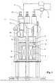
- FIG. 1 shows a cryostat 1 according to the invention with a first helium tank 4 arranged in the cryostat 1 , in which there is a magnetic coil 3 for generating a highly homogeneous magnetic field.
- a second helium tank 2 is arranged, which is separated by a thermal barrier 5 from the first helium tank 4 .
- the second helium tank 2 is liquid helium at atmospheric pressure p 0 or at a relative to the atmospheric pressure p 0 slightly elevated pressure level p 1 at a temperature of about 3K, preferably 4.2K.
- the two helium tanks 2, 4 communicate with each other, so that helium from the upper, second helium tank 2 can flow into the lower first helium tank 4, where the helium with the aid of a cooling device 6 to a temperature well below 3K, preferably on 1.8K, cooled (overcooled).
- a cooling device 6 to a temperature well below 3K, preferably on 1.8K, cooled (overcooled).
- helium is pumped off via the cooling device 6 by a pump 7 and expanded by means of a Joule-Thomson valve.
- a heat exchanger which may be formed in the form of the surface 8 of the cooling device 6, causes a supercooling of the helium in the first helium tank 4.
- the helium pumped and expanded via the cooling device 6 is guided via a return line 9 into a pressure equalization tank 10, of which from the helium in the second helium tank 2 is passed.
- the return of the expanded helium takes place along a refrigerator 11 which cools the expanded helium to 4.2K and liquefies again.
- the helium removed via the cooling device 6 is therefore fed back to the second helium tank 2 via a closed circuit, so that refilling of the second helium tank 2 during normal operation is not necessary.
- the magnetic system arranged in the cryostat in FIG. 1 is part of a high-resolution NMR spectrometer with a high magnetic field strength in the range around or above 18 Tesla.
- the cryostat according to the invention an improved measuring operation is possible, since the number of Heliumnach spallvor réelle can be significantly reduced.
- the second helium tank 2 which is a relatively large in known magnetic systems Inventory of helium can, in the magnet system according to the invention therefore be designed much smaller.
- the second helium tank 2 met Here mainly a hydrostatic function, namely the retention of the Atmospheric pressure or the increased pressure level in the first helium tank 4th
- the surge tank 10 is used to compensate for pressure fluctuations within the return line 9. Will, for example, more helium from the pump 7 pumped by the cooling device 6 than by the refrigerator 11 in the second Helium tank 2 liquefied, then the excess helium in the surge tank 10 saved.
- a heating device for the opposite case, namely that the refrigerator 11 liquefied more helium than pumped out of the first helium tank 4 is advantageously provided in the magnet system, a heating device, with the help of which the liquefaction amount of the refrigerator 11 is regulated can be.
- the system according to the invention should be set so that the refrigerator 11 liquefied more helium when switched off heater than is pumped by the pump 7 through the cooling device 6.
- the refrigerator 11 of Fig. 1 is formed in two stages to cool the helium to its boiling temperature.
- the first stage 13 of the refrigerator 11 can be thermally conductively connected to a radiation shield 15 arranged in the cryostat 1.
- the radiation shield 15 serves to reduce incident radiant energy and is usually at least partially designed as a nitrogen tank 16 , which holds the radiation shield 15 at about 40K.
- the cooling of the radiation shield 15 can take place via the refrigerator 11, so that it is possible to dispense with a nitrogen tank 16.
- the cold end of the second stage 14 of the tube cooler 11 projects into the second helium tank 2 to cool the helium in the second tank and bring the recycled helium to its boiling point and liquefy.
- FIG. 2 A detailed representation of the built-in magnet system in the refrigerator 11 is shown in Fig. 2 .
- a separation projects to the vacuum 17 through the radiation shield 15.
- the refrigerator 11 is located within the separation to the vacuum 17 and is fixed by a flange 18 at this thermally conductive.
- the helium pumped off via the cooling device 6 is guided via the return line 9 along the refrigerator 11 (not visible) into the cold end 19 of the refrigerator 11, where it liquefies and is returned through the outlet 20 into the second helium tank 2.
- the refrigerator 11 comprises a regenerator material with a phase transition.
- the phase transition causes an increase in the volumetric specific heat of the regenerator material and allows the helium to cool to below 3K.
- Suitable regenerator materials include Pb and rare earth compounds such as HoCo, Er 3 Ni, ErNi, GdAlO 3, and ErNi 0.9 Co 0.1 .
- these materials have a magnetic phase transition that can be troublesome in the context of magnetic applications.
- the magnet system according to the invention therefore provides for magnetically shielding the regenerator material in the cryostat 1.
- the cryostat 1 may be equipped with a pressure relief valve, by which helium can escape into the atmosphere upon heating of the helium, for example by a quench of the solenoid coil 3 or in the event of failure of the refrigerator 11, to an unwanted increase in pressure within to avoid the helium tanks.
- a refilling of helium in the second helium tank 2 may be necessary, which can be done via a filling device 1 2.
- the pressure relief valve is placed in neck or suspension tubes for reasons of space, in which no refrigerator is installed, so that the excess evaporated helium passes through gaps in the neck or suspension tubes into the atmosphere.
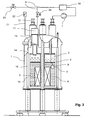
- FIG. 3 shows an advantageous development of the cryostat 1 shown in FIG. 1, in which a pressure relief valve 22 opens in the event of failure of the refrigerator 11 to the environment in such a way that helium evaporating from the second helium tank 2 is guided along the refrigerator 11.
- the evaporating helium is released via a line 21 into the atmosphere.
- a heat input via the (non-active) refrigerator 11 is thus at least greatly reduced, so that the cryostat 1 is in a state which comes close to the state of a cryostat without the refrigerator 11.
- the line 9 is additionally provided with a further valve 23 and a valve 24 equipped such that when opening the pressure relief valve 22 and the funded through the line 9 helium is discharged through a valve 23 directly to the environment.
- the valve 23 is designed as a check valve, so that no ambient air can enter the cryostat and opens in case of failure of the refrigerator 11 or opening of the pressure relief valve 22. Simultaneously or delayed in time closes the valve 24 to return the pumped by the pump helium in the second helium tank 2 to prevent.
- the cryostat 1 can thus be operated in two modes, namely in a normal mode and a fault mode.
- the valves 23 and 24 which are preferably designed as solenoid valves, from normal operation to interference mode.
- This embodiment makes it possible to operate the cryostat for a relatively long time even in the event of a fault, since the helium consumption is not excessively increased by the fact that the structures in the area (tower) of the refrigerator 11 warm up uncooled and make it to an extreme entry in this way from heat enters the second helium tank 2.
- the inventive cryostat 1 reduces in the manner described above, this heat input into the second helium tank 2 crucial and thus enables a more compact design of the cryostat 1, which can be operated for a long time even in case of failure of the refrigerator 11.
Landscapes
- Physics & Mathematics (AREA)
- Engineering & Computer Science (AREA)
- Mechanical Engineering (AREA)
- Thermal Sciences (AREA)
- General Engineering & Computer Science (AREA)
- Condensed Matter Physics & Semiconductors (AREA)
- General Physics & Mathematics (AREA)
- Chemical & Material Sciences (AREA)
- Combustion & Propulsion (AREA)
- Containers, Films, And Cooling For Superconductive Devices (AREA)
Abstract
Description
- Fig. 1
- eine schematische Darstellung eines erfindungsgemäßen Kryostaten mit eingebautem Refrigerator;
- Fig. 2
- eine detaillierte schematische Darstellung des in dem erfindungsgemäßen Kryostaten eingebauten Refrigerators; und
- Fig. 3
- eine schematische Darstellung eines erfindungsgemäßen Kryostaten mit Überdruckventil am zweiten Helium-Tank.
- 1
- Kryostat
- 2
- zweiter Helium-Tank
- 3
- Magnetspule
- 4
- erster Helium-Tank
- 5
- thermische Barriere
- 6
- Kühleinrichtung
- 7
- Pumpe
- 8
- Oberfläche der Kühleinrichtung
- 9
- Rückleitung
- 10
- Druckausgleichsbehälter
- 11
- Refrigerator
- 12
- Einfülleinrichtung (Turm)
- 13
- 1. Stufe des Pulsrohrkühlers
- 14
- 2. Stufe des Pulsrohrkühlers
- 15
- Strahlungsschild
- 16
- Stickstofftank
- 17
- Abtrennung zum Vakuum
- 18
- Flanschverbindung
- 19
- kaltes Ende des Pulsrohrkühlers
- 20
- Auslass verflüssigtes Helium
- 21
- Leitung
- 22
- Überdruckventil
- 23
- Überdruck- und Rückschlagventil
- 24
- Ventil
Claims (18)
- Kryostat (1) mit einem ersten Helium-Tank (4), der Helium mit einer Betriebstemperatur T1 < 3K enthält und einen zweiten Helium-Tank (2), der mit dem ersten Helium-Tank (4) in Verbindung steht und flüssiges Helium bei einer Betriebstemperatur T2 > 3K enthält, wobei im ersten Helium-Tank (4) eine Kühleinrichtung (6) vorgesehen ist, die im ersten Helium-Tank (4) eine Betriebstemperatur T1 < 3K erzeugt, und wobei die Kühleinrichtung (6) als Joule-Thomson-Ventil mit nachgeschaltetem Wärmetauscher ausgeführt ist, aus welchem abgepumptes Helium in einen Raumtemperatur-Bereich außerhalb des Kryostaten (1) gefördert wird
dadurch gekennzeichnet, dass ein Refrigerator (11) vorgesehen ist, dessen kaltes Ende (19) in den zweiten Helium-Tank (2) ragt, und dass im Normalbetrieb das geförderte Helium in einem geschlossenen Kreislauf entlang dem Refrigerator (11) in den zweiten Helium-Tank (2) zurück geführt, dabei vorgekühlt und am kalten Ende (19) des Refrigerators (11) verflüssigt wird. - Kryostat (1) nach Anspruch 1, dadurch gekennzeichnet, dass der Kryostat (1) im ersten Helium-Tank (4) ein supraleitendes Magnetsystem, insbesondere eine Apparatur der magnetischen Resonanz enthält.
- Kryostat (1) nach einem der vorhergehenden Ansprüche, dadurch gekennzeichnet, dass der Refrigerator (11) als Pulsrohrkühler ausgebildet ist.
- Kryostat (1) nach einem der vorhergehenden Ansprüche, dadurch gekennzeichnet, dass der Refrigerator (11) mehrstufig, vorzugsweise zweistufig ausgeführt ist.
- Kryostat (1) nach Anspruch 4, dadurch gekennzeichnet, dass eine Stufe des Refrigerators (11) vor dem kalten Ende (19) mit einem im Kryostaten (1) angeordneten Strahlungsschild (15) thermisch leitend verbunden ist.
- Kryostat (1) nach Anspruch 5, dadurch gekennzeichnet, dass der mit der 1. Stufe des Refrigerators (11) verbundene Strahlungsschild (15) die Helium-Tanks (2, 4) umgibt, und dass die Kühlleistung des Refrigerators (11) ausreicht, einen Tank (16) mit flüssigem Stickstoff zu ersetzen.
- Kryostat (1) nach einem der vorhergehenden Ansprüche, dadurch gekennzeichnet, dass der Refrigerator (11) als Regenerator-Material eine Substanz mit einem Phasenübergang, insbesondere einem magnetischen Phasenübergang enthält.
- Kryostat (1) nach Anspruch 7, dadurch gekennzeichnet, dass das Regenerator-Material im Kryostaten (1) magnetisch abgeschirmt ist.
- Kryostat (1) nach einem der vorhergehenden Ansprüche, dadurch gekennzeichnet, dass der Refrigerator (11) als Regenerator-Material eine Substanz mit einem Phasenübergang enthält, wobei der Phasenübergang nicht magnetisch ist.
- Kryostat (1) nach einem der vorhergehenden Ansprüche, dadurch gekennzeichnet, dass der Refrigerator (11) Helium als Regenerator-Material enthält.
- Kryostat (1) nach einem der vorhergehenden Ansprüche, dadurch gekennzeichnet, dass der den Regenerator enthaltende Abschnitt des Refrigerators (11) an einer Stelle im Kryostaten (1) angeordnet ist, an der im Betrieb ein minimales Magnetfeld herrscht.
- Kryostat (1) nach einem der vorhergehenden Ansprüche, dadurch gekennzeichnet, dass der Kryostat (1) und der Refrigerator (11) so ausgelegt und dimensioniert sind, dass im Betrieb kein Helium in den Kryostaten (1) nachgefüllt werden muss.
- Kryostat (1) nach einem der vorhergehenden Ansprüche, dadurch gekennzeichnet, dass der zweite Helium-Tank (2) oberhalb des ersten Helium-Tanks (4) angeordnet ist.
- Kryostat (1) nach einem der vorhergehenden Ansprüche, dadurch gekennzeichnet, dass der geschlossene Heliumkreislauf eine Rückleitung (9) zur Rückführung des geförderten Heliums umfasst, in der, vorzugsweise außerhalb des Kryostaten(1), ein Druckausgleichsbehälter (10) angeordnet ist.
- Kryostat (1) nach einem der vorhergehenden Ansprüche, dadurch gekennzeichnet, dass im zweiten Helium-Tank (2) eine Heizvorrichtung zur Erwärmung des Heliums vorgesehen ist.
- Kryostat (1) nach einem der vorhergehenden Ansprüche, dadurch gekennzeichnet, dass am Kryostaten (1) eine Einrichtung (12) zum Einfüllen von Helium vorgesehen ist, die zumindest mit einem der Helium-Tanks (2, 4) verbunden ist.
- Kryostat (1) nach einem der vorhergehenden Ansprüche, dadurch gekennzeichnet, dass der zweite Helium-Tank (2) flüssiges Helium mit einer Temperatur von ungefähr 4,2K enthält, wobei die beiden Helium-Tanks (2, 4) derart verbunden sind, dass sich das Helium in beiden Helium-Tanks (2, 4) auf einem gegenüber Atmosphärendruck p0 leicht erhöhtem Druckniveau p1 befindet.
- Kryostat (1) nach Anspruch 16, dadurch gekennzeichnet, dass Mittel vorgesehen sind, die bewirken, dass bei Ausfall des Refrigerators (11) am zweiten Helium-Tank (2) ein Überdruckventil (22) zur Umgebung öffnet, derart, dass aus dem zweiten Helium-Tank (2) abdampfendes Helium entlang des Refrigerators (11) geführt wird und dabei Enthalpie an den Refrigerator (11) abgibt, um dadurch den Wärmeeintrag in den zweiten Helium-Tank (2) zu minimieren.
Priority Applications (1)
| Application Number | Priority Date | Filing Date | Title |
|---|---|---|---|
| US11/055,069 US7318318B2 (en) | 2004-03-13 | 2005-02-11 | Superconducting magnet system with refrigerator |
Applications Claiming Priority (2)
| Application Number | Priority Date | Filing Date | Title |
|---|---|---|---|
| DE200410012416 DE102004012416B4 (de) | 2004-03-13 | 2004-03-13 | Supraleitendes Magnetsystem mit Pulsrohr-Kühler |
| DE102004012416 | 2004-03-13 |
Publications (3)
| Publication Number | Publication Date |
|---|---|
| EP1574777A2 true EP1574777A2 (de) | 2005-09-14 |
| EP1574777A3 EP1574777A3 (de) | 2010-12-01 |
| EP1574777B1 EP1574777B1 (de) | 2012-02-29 |
Family
ID=34813692
Family Applications (1)
| Application Number | Title | Priority Date | Filing Date |
|---|---|---|---|
| EP20040024133 Not-in-force EP1574777B1 (de) | 2004-03-13 | 2004-10-09 | Kryostat für ein supraleitendes Magnetsystem |
Country Status (2)
| Country | Link |
|---|---|
| EP (1) | EP1574777B1 (de) |
| DE (1) | DE102004012416B4 (de) |
Cited By (6)
| Publication number | Priority date | Publication date | Assignee | Title |
|---|---|---|---|---|
| EP2000735A1 (de) * | 2007-06-08 | 2008-12-10 | Hitachi, Ltd. | Kühlsystem für einen kryogenischen Speicherbehälter und Betriebsverfahren dafür |
| EP1628109A3 (de) * | 2004-07-30 | 2009-03-25 | Bruker BioSpin AG | Kryostatanordnung |
| EP2821741A3 (de) * | 2013-07-03 | 2015-05-20 | Bruker BioSpin AG | Verfahren zum Umrüsten einer Kryostatanordnung auf Umlaufkühlung |
| CN104237817B (zh) * | 2014-09-26 | 2016-11-30 | 苏州露宇电子科技有限公司 | 核磁共振磁体恒温装置 |
| CN107808733A (zh) * | 2017-12-12 | 2018-03-16 | 合肥中科离子医学技术装备有限公司 | 一种用于低温系统降温插拔式输液管 |
| CN117128442A (zh) * | 2023-08-07 | 2023-11-28 | 北京航天试验技术研究所 | 一种恒温恒压低温杜瓦、系统及其方法 |
Families Citing this family (3)
| Publication number | Priority date | Publication date | Assignee | Title |
|---|---|---|---|---|
| DE102010038713B4 (de) * | 2010-07-30 | 2013-08-01 | Bruker Biospin Gmbh | Hochfeld-NMR-Apparatur mit Überschuss-Kühlleistung und integrierter Helium-Rückverflüssigung |
| CN105489356B (zh) * | 2015-12-28 | 2018-07-17 | 芜湖国睿兆伏电子有限公司 | 一种超高压脉冲变压器 |
| DE102016218000B3 (de) | 2016-09-20 | 2017-10-05 | Bruker Biospin Gmbh | Kryostatenanordnung mit einem Vakuumbehälter und einem zu kühlenden Objekt, mit evakuierbarem Hohlraum |
Citations (4)
| Publication number | Priority date | Publication date | Assignee | Title |
|---|---|---|---|---|
| US5220800A (en) * | 1990-12-10 | 1993-06-22 | Bruker Analytische Messtechnik Gmbh | Nmr magnet system with superconducting coil in a helium bath |
| US5381666A (en) * | 1990-06-08 | 1995-01-17 | Hitachi, Ltd. | Cryostat with liquefaction refrigerator |
| JP2002124410A (ja) * | 2000-10-17 | 2002-04-26 | Japan Magnet Technol Kk | 超電導磁石装置の冷却装置 |
| DE10226498A1 (de) * | 2002-06-14 | 2004-01-08 | Bruker Biospin Gmbh | Kryostatenanordnung mit verbesserten Eigenschaften |
Family Cites Families (2)
| Publication number | Priority date | Publication date | Assignee | Title |
|---|---|---|---|---|
| JPH07105529B2 (ja) * | 1984-07-11 | 1995-11-13 | 株式会社東芝 | 超流動ヘリウム発生装置 |
| JPH11288809A (ja) * | 1998-03-31 | 1999-10-19 | Toshiba Corp | 超電導マグネット装置 |
-
2004
- 2004-03-13 DE DE200410012416 patent/DE102004012416B4/de not_active Expired - Fee Related
- 2004-10-09 EP EP20040024133 patent/EP1574777B1/de not_active Not-in-force
Patent Citations (4)
| Publication number | Priority date | Publication date | Assignee | Title |
|---|---|---|---|---|
| US5381666A (en) * | 1990-06-08 | 1995-01-17 | Hitachi, Ltd. | Cryostat with liquefaction refrigerator |
| US5220800A (en) * | 1990-12-10 | 1993-06-22 | Bruker Analytische Messtechnik Gmbh | Nmr magnet system with superconducting coil in a helium bath |
| JP2002124410A (ja) * | 2000-10-17 | 2002-04-26 | Japan Magnet Technol Kk | 超電導磁石装置の冷却装置 |
| DE10226498A1 (de) * | 2002-06-14 | 2004-01-08 | Bruker Biospin Gmbh | Kryostatenanordnung mit verbesserten Eigenschaften |
Non-Patent Citations (1)
| Title |
|---|
| DATABASE WPI Week 198611 Thomson Scientific, London, GB; AN 1986-072341 XP002606619, -& JP 61 022158 A (TOSHIBA KK) 30. Januar 1986 (1986-01-30) * |
Cited By (8)
| Publication number | Priority date | Publication date | Assignee | Title |
|---|---|---|---|---|
| EP1628109A3 (de) * | 2004-07-30 | 2009-03-25 | Bruker BioSpin AG | Kryostatanordnung |
| EP2000735A1 (de) * | 2007-06-08 | 2008-12-10 | Hitachi, Ltd. | Kühlsystem für einen kryogenischen Speicherbehälter und Betriebsverfahren dafür |
| EP2821741A3 (de) * | 2013-07-03 | 2015-05-20 | Bruker BioSpin AG | Verfahren zum Umrüsten einer Kryostatanordnung auf Umlaufkühlung |
| US9494344B2 (en) | 2013-07-03 | 2016-11-15 | Bruker Biospin Ag | Method for reconfiguring a cryostat configuration for recirculation cooling |
| CN104237817B (zh) * | 2014-09-26 | 2016-11-30 | 苏州露宇电子科技有限公司 | 核磁共振磁体恒温装置 |
| CN107808733A (zh) * | 2017-12-12 | 2018-03-16 | 合肥中科离子医学技术装备有限公司 | 一种用于低温系统降温插拔式输液管 |
| CN117128442A (zh) * | 2023-08-07 | 2023-11-28 | 北京航天试验技术研究所 | 一种恒温恒压低温杜瓦、系统及其方法 |
| CN117128442B (zh) * | 2023-08-07 | 2024-05-17 | 北京航天试验技术研究所 | 一种恒温恒压低温杜瓦、系统及其方法 |
Also Published As
| Publication number | Publication date |
|---|---|
| DE102004012416A1 (de) | 2005-09-29 |
| EP1574777A3 (de) | 2010-12-01 |
| EP1574777B1 (de) | 2012-02-29 |
| DE102004012416B4 (de) | 2006-04-20 |
Similar Documents
| Publication | Publication Date | Title |
|---|---|---|
| DE102004037172B4 (de) | Kryostatanordnung | |
| EP1628089B1 (de) | Vorrichtung zur Kühlung einer Kryostatanordnung | |
| DE102004053972B3 (de) | NMR-Spektrometer mit gemeinsamen Refrigerator zum Kühlen von NMR-Probenkopf und Kryostat | |
| EP1736723B1 (de) | Kryostatanordnung mit Kryokühler | |
| DE69838866T2 (de) | Verbesserungen in oder mit Bezug auf Kryostatsystemen | |
| EP2821741B1 (de) | Verfahren zum Umrüsten einer Kryostatanordnung auf Umlaufkühlung | |
| DE102011078608B4 (de) | Kryostatanordnung | |
| DE102005041383B4 (de) | NMR-Apparatur mit gemeinsam gekühltem Probenkopf und Kryobehälter und Verfahren zum Betrieb derselben | |
| EP3285032B1 (de) | Kryostatanordnung und verfahren zum betrieb davon | |
| EP3230666B1 (de) | Kryostat mit einem ersten und einem zweiten heliumtank, die zumindest in einem unteren bereich flüssigkeitsdicht voneinander abgetrennt sind | |
| DE69828128T2 (de) | Magnetanordnung für die Kernspinresonanz mit einem Halsrohr, in dem ein Pulsrohrkühler untergebracht ist | |
| EP3488451A1 (de) | Vorrichtung und verfahren zum unterkühlten betrieb eines kryostaten mit geringen mengen kühlmittel | |
| DE102004053973B3 (de) | NMR-Spektrometer mit Refrigeratorkühlung | |
| DE102016214731B3 (de) | NMR-Apparatur mit supraleitender Magnetanordnung sowie gekühlten Probenkopfkomponenten | |
| EP1617157A2 (de) | Kryostatanordnung mit Kryokühler und Gasspaltwärmeübertrager | |
| DE10226498B4 (de) | Kryostatenanordnung mit verbesserten Eigenschaften | |
| EP1574777B1 (de) | Kryostat für ein supraleitendes Magnetsystem | |
| EP1742234B1 (de) | Unterkühlte Horizontalkryostatanordnung | |
| DE102010028750B4 (de) | Verlustarme Kryostatenanordnung | |
| EP3611528A1 (de) | Kryostatanordnung mit supraleitendem magnetspulensystem mit thermischer verankerung der befestigungsstruktur | |
| DE102004012452A1 (de) | Supraleitendes Magnetsystem mit Pulsrohr-Kühler | |
| EP4343196A1 (de) | Vorrichtung zum transfer von flüssigem helium, mit verringerten transfer-verlusten |
Legal Events
| Date | Code | Title | Description |
|---|---|---|---|
| PUAI | Public reference made under article 153(3) epc to a published international application that has entered the european phase |
Free format text: ORIGINAL CODE: 0009012 |
|
| AK | Designated contracting states |
Kind code of ref document: A2 Designated state(s): AT BE BG CH CY CZ DE DK EE ES FI FR GB GR HU IE IT LI LU MC NL PL PT RO SE SI SK TR |
|
| AX | Request for extension of the european patent |
Extension state: AL HR LT LV MK |
|
| PUAL | Search report despatched |
Free format text: ORIGINAL CODE: 0009013 |
|
| AK | Designated contracting states |
Kind code of ref document: A3 Designated state(s): AT BE BG CH CY CZ DE DK EE ES FI FR GB GR HU IE IT LI LU MC NL PL PT RO SE SI SK TR |
|
| AX | Request for extension of the european patent |
Extension state: AL HR LT LV MK |
|
| RIC1 | Information provided on ipc code assigned before grant |
Ipc: F17C 3/08 20060101ALI20101025BHEP Ipc: F17C 13/00 20060101AFI20041202BHEP Ipc: G01R 33/3815 20060101ALI20101025BHEP |
|
| 17P | Request for examination filed |
Effective date: 20110326 |
|
| 17Q | First examination report despatched |
Effective date: 20110506 |
|
| AKX | Designation fees paid |
Designated state(s): CH DE FR GB LI |
|
| REG | Reference to a national code |
Ref country code: DE Ref legal event code: R079 Ref document number: 502004013330 Country of ref document: DE Free format text: PREVIOUS MAIN CLASS: F17C0013000000 Ipc: G01R0033380000 |
|
| GRAP | Despatch of communication of intention to grant a patent |
Free format text: ORIGINAL CODE: EPIDOSNIGR1 |
|
| RIC1 | Information provided on ipc code assigned before grant |
Ipc: F17C 13/00 20060101ALI20110920BHEP Ipc: F25B 9/02 20060101ALI20110920BHEP Ipc: F25B 9/14 20060101ALI20110920BHEP Ipc: F25D 19/00 20060101ALI20110920BHEP Ipc: G01R 33/38 20060101AFI20110920BHEP |
|
| RTI1 | Title (correction) |
Free format text: CRYOSTAT FOR A SUPERCONDUCTING MAGNET SYSTEM |
|
| GRAS | Grant fee paid |
Free format text: ORIGINAL CODE: EPIDOSNIGR3 |
|
| GRAA | (expected) grant |
Free format text: ORIGINAL CODE: 0009210 |
|
| AK | Designated contracting states |
Kind code of ref document: B1 Designated state(s): CH DE FR GB LI |
|
| REG | Reference to a national code |
Ref country code: GB Ref legal event code: FG4D Free format text: NOT ENGLISH Ref country code: CH Ref legal event code: EP |
|
| REG | Reference to a national code |
Ref country code: DE Ref legal event code: R096 Ref document number: 502004013330 Country of ref document: DE Effective date: 20120426 |
|
| PLBE | No opposition filed within time limit |
Free format text: ORIGINAL CODE: 0009261 |
|
| STAA | Information on the status of an ep patent application or granted ep patent |
Free format text: STATUS: NO OPPOSITION FILED WITHIN TIME LIMIT |
|
| 26N | No opposition filed |
Effective date: 20121130 |
|
| REG | Reference to a national code |
Ref country code: DE Ref legal event code: R097 Ref document number: 502004013330 Country of ref document: DE Effective date: 20121130 |
|
| REG | Reference to a national code |
Ref country code: FR Ref legal event code: PLFP Year of fee payment: 12 |
|
| REG | Reference to a national code |
Ref country code: FR Ref legal event code: PLFP Year of fee payment: 13 |
|
| REG | Reference to a national code |
Ref country code: FR Ref legal event code: PLFP Year of fee payment: 14 |
|
| REG | Reference to a national code |
Ref country code: FR Ref legal event code: PLFP Year of fee payment: 15 |
|
| PGFP | Annual fee paid to national office [announced via postgrant information from national office to epo] |
Ref country code: DE Payment date: 20191023 Year of fee payment: 16 |
|
| PGFP | Annual fee paid to national office [announced via postgrant information from national office to epo] |
Ref country code: FR Payment date: 20191022 Year of fee payment: 16 |
|
| PGFP | Annual fee paid to national office [announced via postgrant information from national office to epo] |
Ref country code: CH Payment date: 20191023 Year of fee payment: 16 |
|
| PGFP | Annual fee paid to national office [announced via postgrant information from national office to epo] |
Ref country code: GB Payment date: 20191023 Year of fee payment: 16 |
|
| REG | Reference to a national code |
Ref country code: DE Ref legal event code: R119 Ref document number: 502004013330 Country of ref document: DE |
|
| REG | Reference to a national code |
Ref country code: CH Ref legal event code: PL |
|
| GBPC | Gb: european patent ceased through non-payment of renewal fee |
Effective date: 20201009 |
|
| PG25 | Lapsed in a contracting state [announced via postgrant information from national office to epo] |
Ref country code: DE Free format text: LAPSE BECAUSE OF NON-PAYMENT OF DUE FEES Effective date: 20210501 Ref country code: FR Free format text: LAPSE BECAUSE OF NON-PAYMENT OF DUE FEES Effective date: 20201031 |
|
| PG25 | Lapsed in a contracting state [announced via postgrant information from national office to epo] |
Ref country code: LI Free format text: LAPSE BECAUSE OF NON-PAYMENT OF DUE FEES Effective date: 20201031 Ref country code: GB Free format text: LAPSE BECAUSE OF NON-PAYMENT OF DUE FEES Effective date: 20201009 Ref country code: CH Free format text: LAPSE BECAUSE OF NON-PAYMENT OF DUE FEES Effective date: 20201031 |