EP1998232B1 - Entwicklungsvorrichtung und Bilderzeugungsvorrichtung - Google Patents
Entwicklungsvorrichtung und Bilderzeugungsvorrichtung Download PDFInfo
- Publication number
- EP1998232B1 EP1998232B1 EP08157292.7A EP08157292A EP1998232B1 EP 1998232 B1 EP1998232 B1 EP 1998232B1 EP 08157292 A EP08157292 A EP 08157292A EP 1998232 B1 EP1998232 B1 EP 1998232B1
- Authority
- EP
- European Patent Office
- Prior art keywords
- developer
- agitator
- container
- toner
- development
- Prior art date
- Legal status (The legal status is an assumption and is not a legal conclusion. Google has not performed a legal analysis and makes no representation as to the accuracy of the status listed.)
- Ceased
Links
- 238000011161 development Methods 0.000 title claims description 71
- 230000003247 decreasing effect Effects 0.000 claims description 3
- 230000005484 gravity Effects 0.000 claims description 3
- 238000011144 upstream manufacturing Methods 0.000 claims description 2
- 238000012546 transfer Methods 0.000 description 56
- 238000000034 method Methods 0.000 description 19
- 230000008569 process Effects 0.000 description 17
- 239000002245 particle Substances 0.000 description 16
- 238000003384 imaging method Methods 0.000 description 12
- 230000004048 modification Effects 0.000 description 12
- 238000012986 modification Methods 0.000 description 12
- 238000003756 stirring Methods 0.000 description 12
- 238000013019 agitation Methods 0.000 description 11
- 239000006185 dispersion Substances 0.000 description 9
- 230000007246 mechanism Effects 0.000 description 9
- 238000004140 cleaning Methods 0.000 description 6
- 239000000203 mixture Substances 0.000 description 5
- 230000015556 catabolic process Effects 0.000 description 4
- 238000006731 degradation reaction Methods 0.000 description 4
- 239000000463 material Substances 0.000 description 3
- 230000003287 optical effect Effects 0.000 description 2
- 230000002093 peripheral effect Effects 0.000 description 2
- 238000007639 printing Methods 0.000 description 2
- 230000009467 reduction Effects 0.000 description 2
- 230000002159 abnormal effect Effects 0.000 description 1
- 238000005056 compaction Methods 0.000 description 1
- 230000001419 dependent effect Effects 0.000 description 1
- 238000000151 deposition Methods 0.000 description 1
- 230000002542 deteriorative effect Effects 0.000 description 1
- 238000005516 engineering process Methods 0.000 description 1
- 238000002474 experimental method Methods 0.000 description 1
Images




Classifications
-
- G—PHYSICS
- G03—PHOTOGRAPHY; CINEMATOGRAPHY; ANALOGOUS TECHNIQUES USING WAVES OTHER THAN OPTICAL WAVES; ELECTROGRAPHY; HOLOGRAPHY
- G03G—ELECTROGRAPHY; ELECTROPHOTOGRAPHY; MAGNETOGRAPHY
- G03G21/00—Arrangements not provided for by groups G03G13/00 - G03G19/00, e.g. cleaning, elimination of residual charge
- G03G21/10—Collecting or recycling waste developer
- G03G21/105—Arrangements for conveying toner waste
-
- G—PHYSICS
- G03—PHOTOGRAPHY; CINEMATOGRAPHY; ANALOGOUS TECHNIQUES USING WAVES OTHER THAN OPTICAL WAVES; ELECTROGRAPHY; HOLOGRAPHY
- G03G—ELECTROGRAPHY; ELECTROPHOTOGRAPHY; MAGNETOGRAPHY
- G03G15/00—Apparatus for electrographic processes using a charge pattern
- G03G15/06—Apparatus for electrographic processes using a charge pattern for developing
- G03G15/08—Apparatus for electrographic processes using a charge pattern for developing using a solid developer, e.g. powder developer
- G03G15/0822—Arrangements for preparing, mixing, supplying or dispensing developer
- G03G15/0865—Arrangements for supplying new developer
- G03G15/0867—Arrangements for supplying new developer cylindrical developer cartridges, e.g. toner bottles for the developer replenishing opening
- G03G15/087—Developer cartridges having a longitudinal rotational axis, around which at least one part is rotated when mounting or using the cartridge
-
- G—PHYSICS
- G03—PHOTOGRAPHY; CINEMATOGRAPHY; ANALOGOUS TECHNIQUES USING WAVES OTHER THAN OPTICAL WAVES; ELECTROGRAPHY; HOLOGRAPHY
- G03G—ELECTROGRAPHY; ELECTROPHOTOGRAPHY; MAGNETOGRAPHY
- G03G15/00—Apparatus for electrographic processes using a charge pattern
- G03G15/06—Apparatus for electrographic processes using a charge pattern for developing
- G03G15/08—Apparatus for electrographic processes using a charge pattern for developing using a solid developer, e.g. powder developer
- G03G15/0822—Arrangements for preparing, mixing, supplying or dispensing developer
- G03G15/0877—Arrangements for metering and dispensing developer from a developer cartridge into the development unit
-
- G—PHYSICS
- G03—PHOTOGRAPHY; CINEMATOGRAPHY; ANALOGOUS TECHNIQUES USING WAVES OTHER THAN OPTICAL WAVES; ELECTROGRAPHY; HOLOGRAPHY
- G03G—ELECTROGRAPHY; ELECTROPHOTOGRAPHY; MAGNETOGRAPHY
- G03G15/00—Apparatus for electrographic processes using a charge pattern
- G03G15/06—Apparatus for electrographic processes using a charge pattern for developing
- G03G15/08—Apparatus for electrographic processes using a charge pattern for developing using a solid developer, e.g. powder developer
- G03G15/0822—Arrangements for preparing, mixing, supplying or dispensing developer
- G03G15/0877—Arrangements for metering and dispensing developer from a developer cartridge into the development unit
- G03G15/0879—Arrangements for metering and dispensing developer from a developer cartridge into the development unit for dispensing developer from a developer cartridge not directly attached to the development unit
-
- G—PHYSICS
- G03—PHOTOGRAPHY; CINEMATOGRAPHY; ANALOGOUS TECHNIQUES USING WAVES OTHER THAN OPTICAL WAVES; ELECTROGRAPHY; HOLOGRAPHY
- G03G—ELECTROGRAPHY; ELECTROPHOTOGRAPHY; MAGNETOGRAPHY
- G03G2215/00—Apparatus for electrophotographic processes
- G03G2215/08—Details of powder developing device not concerning the development directly
- G03G2215/0802—Arrangements for agitating or circulating developer material
- G03G2215/0816—Agitator type
- G03G2215/0819—Agitator type two or more agitators
-
- G—PHYSICS
- G03—PHOTOGRAPHY; CINEMATOGRAPHY; ANALOGOUS TECHNIQUES USING WAVES OTHER THAN OPTICAL WAVES; ELECTROGRAPHY; HOLOGRAPHY
- G03G—ELECTROGRAPHY; ELECTROPHOTOGRAPHY; MAGNETOGRAPHY
- G03G2215/00—Apparatus for electrophotographic processes
- G03G2215/08—Details of powder developing device not concerning the development directly
- G03G2215/0802—Arrangements for agitating or circulating developer material
- G03G2215/0816—Agitator type
- G03G2215/0827—Augers
-
- G—PHYSICS
- G03—PHOTOGRAPHY; CINEMATOGRAPHY; ANALOGOUS TECHNIQUES USING WAVES OTHER THAN OPTICAL WAVES; ELECTROGRAPHY; HOLOGRAPHY
- G03G—ELECTROGRAPHY; ELECTROPHOTOGRAPHY; MAGNETOGRAPHY
- G03G2215/00—Apparatus for electrophotographic processes
- G03G2215/08—Details of powder developing device not concerning the development directly
- G03G2215/0802—Arrangements for agitating or circulating developer material
- G03G2215/085—Stirring member in developer container
Definitions
- Exemplary aspects of the present invention relate to a development device and an image forming apparatus, and more particularly, to a development device and an image forming apparatus for efficiently agitating a two-component developer.
- a related-art image forming apparatus such as a copier, a facsimile machine, a printer, or a multifunction printer having at least one of copying, printing, scanning, and facsimile functions, typically forms a toner image on a recording medium (e.g., a transfer sheet) according to image data using electrophotography.
- a recording medium e.g., a transfer sheet
- a charging device charges a surface of a latent image carrier; an optical writer emits a light beam onto the charged surface of the latent image carrier to form an electrostatic latent image on the latent image carrier according to the image data; a development device develops the electrostatic latent image with a developer to form a toner image on the latent image carrier; the toner image is transferred from the latent image carrier onto a transfer sheet; and a fixing device applies heat and pressure to the transfer sheet bearing the toner image to fix the toner image on the transfer sheet, thus transferring the toner image onto the transfer sheet.
- One common type of developer is a two-component developer, which includes toner and a carrier for carrying the toner.
- toner When the developer is agitated and mixed inside the development device, the toner is charged by friction generated between the toner and the carrier and electrostatically attracted to the electrostatic latent image formed on the latent image carrier, thereby forming a toner image.
- One known configuration for a development device includes a development member and an agitation member.
- the agitation member agitates and mixes developer to generate frictional charge between toner and a carrier, and supplies the development member with the developer.
- the development member supplies the developer to a surface of a latent image carrier carrying an electrostatic latent image to develop the electrostatic latent image into a toner image with the developer.
- One known related-art image forming apparatus includes a development device including a paddle for agitating the developer.
- the paddle includes a rotary shaft and a blade radially extending from the rotary shaft, enabling the paddle to rotate to agitate and mix the developer so as to charge the toner by friction.
- the paddle may not contact all of the developer, thereby causing insufficient dispersion and charging of the toner.
- Another known related-art image forming apparatus includes a development device including a screw auger as an agitator.
- a development device including a screw auger as an agitator.
- the screw auger may not sufficiently agitate the developer. Consequently, the toner may not be sufficiently dispersed and charged by friction. Insufficiently charged toner may be adhered to a non-image area in which an electrostatic latent image is not formed on a surface of a latent image carrier, or scatter to other peripheral devices, resulting in degradation of image quality.
- Toner agitation may be improved by increasing a rotation speed of the paddle or the screw auger. However, doing so may increase a load on a drive system for driving the paddle or the screw auger of the development device, or may cause degradation of toner due to heat of friction generated by agitation.
- JP 11-202708 A relates to a image forming device.
- a process unit provided with at least a developing unit, an image carrier and a cleaning means, and a toner supply means are disposed so as to be freely loaded and unloaded with respect to an equipment main body. Then, a first carrying means unidirectionally moving recovered toner, a second carrying means moving the recovered toner to the supply means, a first stirring means carrying and stirring new toner supplied from the supply means and a second stirring means stirring and mixing the recovered toner fed by the carrying means and the new toner are arranged in the cleaning means.
- the toner can be recycled without deteriorating image quality and soiling an image.
- JP 2005-070385 A relates to a development apparatus and image forming apparatus.
- the development apparatus has such configurations that: the developer is circulated and carried by a first stirring member and a second stirring member; a third stirring member which has substantially no ability of carrying the developer in the axial direction is disposed opposing to a part of the second stirring member in the upstream side of the developer carrying direction; and the toner replenished through a toner supply port disposed on the cover of the housing into the opposing part of the second and third stirring members is submerged into the developer by rotation of the second and third stirring members rotated in such a manner that each circumference face moves from the upper side to the lower side.
- the image forming apparatus is equipped with the above developing apparatus.
- US 2002/0154914 A1 relates to a developing cartridge.
- An object of the invention is to make it possible to convey developer from a transfer residual developer accommodating portion to an unused developer accommodating portion without the transfer residual accommodating portion being increased in size more than necessary.
- a first accommodating portion for accommodating unused developer is formed in a housing.
- a second accommodating portion for accommodating transfer residual developer is arranged adjacent to the first accommodating portion.
- US 2003/0053825 A1 relates to an apparatus and method for agitating toner in a container to facilitate toner dispensing in an electrostatographic printer.
- An apparatus and method for dispensing toner in an electrostatographic printer includes apparatus for agitating toner contained by a relatively large toner container (e.g., 10-25 liters in volume).
- Such apparatus includes a substantially vertically-oriented shaft supporting a blade member that operates, as the blade rotates, to drive the contained toner mass upwardly, thereby aerating the mass and preventing compaction during toner dispensing.
- DE 197 42 668 A1 relates to a developer station for electrographic printer or copier.
- the developer station has at least one developer roller and a developer sump containing a rotary paddle roller extending along the developer roller, provided by an inner transport screw for transporting the developer mixture in the axial direction, enclosed by an outer spiral transport device for transporting the developer mixture in the opposite direction.
- JP 04-344668 A relates to a one-component developing device.
- a stirring and supplying member provided with plural apertures and peeling members at parts other than the aperture on the peripheral surface of a cylindrical member is rotatably provided to be close to the developer carrier.
- the peeling member is brought into contact with the surface of the developer carrier to peel the thin layer of the developer formed at a previous developing stage, and the image history is canceled.
- the developer discharged from the aperture is supplied to the carrier to form the uniform thin layer having satisfactory layer thickness by the rotation of the member.
- US 5,561,506 A relates to a developing device for an image forming apparatus having a developer normalizing mechanism independent of a developing mechanism.
- a developing device for developing a latent image electrostatically formed on an image carrier is disclosed.
- the device has a developing mechanism for depositing a toner and carrier mixture, i.e., developer on the image carrier, a developer normalizing mechanism for normalizing the developer and located at a different position from the developing mechanism, and a developer transferring and circulating mechanism for transferring the developer to the developing mechanism and developer normalizing mechanism.
- the device is easy to maintain since the developing mechanism is small in size and simple in configuration.
- FIG. 1 an image forming apparatus 1000 according to an exemplary embodiment of the present invention is described.
- FIG. 1 illustrates one example of the image forming apparatus 1000.
- the image forming apparatus 1000 includes imaging devices 6Y, 6M, 6C, and 6K, primary transfer bias rollers 9Y, 9M, 9C, and 9K, an intermediate transfer unit 10, a secondary transfer roller 19, a fixing device 20, a feeding device 26, a feeding roller 27, a registration roller pair 28, a discharge roller pair 29, a discharge device 30, and a reading device 32.
- the imaging devices 6Y, 6M, 6C, and 6K include photoconductor drums 1Y, 1M, 1C, and 1K, and development devices 5Y, 5M, 5C, and 5K.
- the intermediate transfer unit 10 includes an intermediate transfer belt 8.
- the image forming apparatus 1000 may be a copier, a facsimile machine, a printer, a multifunction printer having at least one of copying, printing, scanning, and facsimile functions, or the like. According to this non-limiting example embodiment, the image forming apparatus 1000 functions as a tandem type color copier for forming a color image on a recording medium (e.g., a transfer sheet) by electrophotography.
- a recording medium e.g., a transfer sheet
- the image forming apparatus 1000 is not limited to the color copier and may form a color and/or monochrome image in other configurations.
- the imaging devices 6Y, 6M, 6C, and 6K are provided side by side to oppose an outer circumferential surface of the intermediate transfer belt 8, serving as an unfixed image carrier, and form yellow, magenta, cyan, and black toner images, respectively.
- the imaging devices 6Y, 6M, 6C, and 6K perform imaging processes for forming a desired toner image on the photoconductor drums 1Y, 1M, 1C, and 1K, respectively.
- the imaging processes include a charging process, an exposure process, a development process, a transfer process, and a cleaning process.
- the imaging processes performed by the imaging device 6Y is described.
- the imaging devices 6M, 6C, and 6K have a structure equivalent to that of the imaging device 6Y.
- a charging device (not shown) is provided around the photoconductor drum 1Y serving as a latent image carrier.
- the charging device uniformly charges a surface of the photoconductor drum 1Y in the charging process.
- An exposure device (not shown, e.g., an optical writer) is provided under the imaging device 6Y and emits a laser beam to the charged surface of the photoconductor drum 1Y based on image information sent from the reading device 32 to form an electrostatic latent image on the photoconductor drum 1Y in the exposure process.
- the development device 5Y supplies a developer to the photoconductor drum 1Y to develop the electrostatic latent image formed on the surface of the photoconductor drum 1Y with toner included in the developer, so that the electrostatic latent image is made visible as a toner image.
- a cleaning device (not shown) collects residual toner remaining on the photoconductor drum 1Y when the surface of the photoconductor drum 1Y, from which the toner image has been transferred to the intermediate transfer belt 8, opposes the cleaning device. Thereafter, a discharge roller (not shown) resets electrical potentials of the surface of the photoconductor drum 1Y.
- the imaging devices 6Y, 6M, 6C, and 6K perform the development process, respectively, the yellow, magenta, cyan, and black toner images formed on the photoconductors 1Y, 1M, 1C, and 1K, respectively, are transferred and superimposed onto the intermediate transfer belt 8, thereby forming a full color toner image on the intermediate transfer belt 8.
- the intermediate transfer roller 8 is sandwiched between the primary transfer bias rollers 9Y, 9M, 9C, and 9K, and the photoconductors 1Y, 1M, 1C, and 1K to form primary transfer nips.
- the primary transfer bias rollers 9Y, 9M, 9C, and 9K are supplied with a transfer bias having a polarity opposite to a polarity of the toner.
- the intermediate transfer belt 8 moves in a direction A and passes the primary transfer nips formed between the primary transfer bias rollers 9Y, 9M, 9C, and 9K and the photoconductors 1Y, 1M, 1C, and 1K, respectively. Accordingly, the yellow, magenta, cyan, and black toner images formed on the photoconductors 1Y, 1M, 1C, and 1K, respectively, are transferred and superimposed onto the intermediate transfer belt 8.
- the intermediate transfer belt 8 opposes the secondary transfer roller 19.
- a recording medium e.g., a transfer sheet P
- the full color toner image formed on the intermediate transfer belt 8 is transferred onto the transfer sheet P.
- the feeding device 26 is provided in a lower portion of the image forming apparatus 1000 and stores a plurality of transfer sheets P.
- the feeding roller 27 separates one transfer sheet P from other transfer sheets P and feeds the transfer sheet P toward the registration roller pair 28.
- the registration roller pair 28 temporarily stops the transfer sheet P, corrects a conveyance direction of the transfer sheet P (e.g., an oblique misalignment), and sends the transfer sheet P toward the secondary transfer nip at a proper time, so that a desired color toner image is transferred onto the transfer sheet P.
- a fixing roller (not shown) and a pressure roller (not shown) of the fixing device 20 fix the color toner image on the transfer sheet P by heat and pressure.
- the transfer sheet P is sent toward the discharge roller pair 29.
- the discharge roller pair 29 discharges the transfer sheet P as an output image to the discharge device 30 provided in an upper portion of the image forming apparatus 1000. Accordingly, the image forming apparatus 1000 finishes a series of image forming processes.
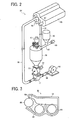
- FIG. 2 is a perspective view of the development device 5Y according to this exemplary embodiment.
- the development device 5Y includes a development member 50, a developer container 51, a toner cartridge 52, a rotary feeder 53, an air pump 54, a circulation path 56, a toner supply path 57, a duct 58, motors 59, 60, and 61, an outlet 67, an inlet 68, and a pipe fittings 77.
- the development devices 5M, 5C, and 5K have a structure equivalent to that of the development device 5Y.
- FIG. 3 is a sectional view of the development member 50.
- the development member 50 includes a casing 62, screws 63 and 64, a development roller 65, and a doctor blade 66.
- the development device 5Y includes a development member (e.g., the development member 50) and a circulation member (e.g., the circulation path 56).
- the development member 50 develops an electrostatic latent image formed on the photoconductor drum 1Y (depicted in FIG. 1 ) with a two-component developer in which a carrier and toner are mixed.
- the circulation path 56 continuously sends the developer discharged from the development member 50 to a developer supplier (e.g., the screws 63 and 64 depicted in FIG. 3 ) of the development member 50.
- the development member 50 is formed into a cartridge.
- the toner cartridge 52 supplies fresh toner to the developer container 51.
- the developer container 51 is separated from the development member 50, and agitates and mixes the developer discharged from the development member 50 and the fresh toner supplied from the toner cartridge 52. After being agitated and mixed, the developer is discharged from the developer container 51 and sent by the rotary feeder 53 toward the development member 50.
- the air pump 54 functions as a driver for generating a driving force for sending the developer to the development member 50Y by air pressure.
- the development member 50 is connected to the developer container 51 via the circulation path 56, serving as a circulation member.
- the circulation path 56 includes an outward path connected to the developer container 51 and a return path connected to one of the screws 63 and 64 (depicted in FIG. 3 ), serving as a developer supplier, of the development member 50.
- the developer moves to the developer container 51 via the outward path of the circulation path 56.
- the developer returns to the development member 50 via the return path of the circulation path 56.
- the motor 59 serves as a driver for supplying toner to the developer container 51.
- the motor 60 functions as a driver for generating a driving force for agitating the developer.
- the motor 61 functions as a driver for generating a driving force for driving the rotary feeder 53. As described later, the rotary feeder 53 is connected to the circulation path 56 and the duct 58 by the pipe fitting 77.
- the screws 63 and 64, and the development roller 65 include a spiral fin and are rotatably supported in the casing 62.
- the casing 62 stores a two-component developer in which toner and a carrier are mixed.
- the rotating screws 63 and 64 may circulate the developer inside the casing 62.
- the developer is discharged from the outlet 67 provided in the development member 50 at an end of the screw 64 (depicted in FIG. 3 ) in an axial direction of the screw 64 to the developer container 51 via the outward path of the circulation path 56.
- a toner density detector (not shown) is provided in a most downstream portion of the screw 64 in a conveyance direction of the developer. Based on a signal transmitted from the toner density detector, the toner cartridge 52 supplies fresh toner to the developer container 51.
- the motor 59 rotates a screw (not shown) of the toner supply path 57 to send the toner discharged from the toner cartridge 52 to the developer container 51.
- the toner is supplied to a portion in front of an entrance of the developer container 51.
- the developer container 51 agitates and mixes the developer after development and the fresh toner, such that the developer may keep a proper toner density and a proper charged amount. After being discharged from the developer container 51, the developer passes through an outlet (not shown) provided in a lower part of the developer container 51 and enters the rotary feeder 53.
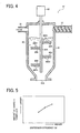
- FIG. 4 is a sectional view of the developer container 51 according to the exemplary embodiment.
- the developer container 51 includes an agitator 80 and an outlet 50A.
- the agitator 80 includes a rotary shaft 80A and a plurality of paddles 80B.
- the paddles 80B are perforated with holes 80B1.
- the developer container 51 has a funnel- or cone-like shape, with a portion of decreasing diameter extending toward the outlet 50A.
- the return path of the developer circulation path 56 and the toner supply path 57 is connected to the developer container 51 near an upper surface of the developer container 51, with the outlet 50A of the developer provided in a lower part thereof.
- the rotary shaft 80A is inserted vertically into the developer container 51 from a horizontal center position of the upper surface of the developer container 51.
- the paddles 80B serving as agitation members, are provided circumferentially about the rotary shaft 80A in an axial direction of the rotary shaft 80A.
- the rotary shaft 80A and the paddles 80B together form an agitator for agitating and mixing developer stored in the developer container 51, developer sent from the outward path of the circulation path 56, and fresh toner particles supplied from the toner cartridge 52 (depicted in FIG. 2 ) via the toner supply path 57.
- the paddles 80B rotate in a direction perpendicular to a direction of developer flow from an upper part of the developer container 51 (e.g., the vicinity of the circulation path 56 and the toner supply path 57) toward the outlet 50A, so as to impede such flow without stopping it.
- the developer passes through the holes 80B1 provided in a surface of the paddles 80B, which push and move the flowing developer as they rotate.
- each hole 80B1 is large enough for at least a carrier included in the developer to pass through. Since a toner particle is smaller than the carrier, it also may pass through the hole 80B1.
- the plurality of paddles 80B serving collectively as an agitation member, rotates to impede the downward flow of the developer in the developer container 51. That is, the developer receives a force applied in the direction perpendicular to the downward flow as well as a force of gravity, so that the developer may be efficiently agitated and mixed in the developer container 51.
- the developer may be mixed with each other, thereby achieving proper dispersion and frictional charging of the developer.
- the developer may be prevented from scattering outside the development device 5Y and adhering to a periphery of the development device 5Y, thereby preventing generation of an abnormal image.
- a number of the paddles 80B provided in a circumferential direction and in an axial direction of the rotary shaft 80A depends on the rotation speed of the rotary shaft 80A (depicted in FIG. 4 ) so as to adjust an amount of the developer passing through the hole 80B1 in the paddle surface of the paddle SOB, thereby appropriately setting a dispersion efficiency.
- Dispersion efficiency corresponds to a degree of mixing of the developer according to a difference of a movement direction of the agitated developer. Therefore, provision of the plurality of holes 80B1 in the paddle 80B may increase a variety of movement directions of the developer, thereby increasing the degree of mixing of the developer, that is, dispersion efficiency of the developer.
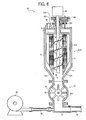
- FIG. 6 is a sectional view of the developer container 51S of the development device 5Y.
- the development device 5Y further includes deceleration gears 73A to 73D.
- the rotary feeder 53 includes a rotor 75 and a stator 76.
- the rotor 75 includes blades 75A.
- the developer container 51S includes a body 51B, a developer inlet 69, an outlet 70, an inner agitator 71, outer agitators 72, and a flange 74.
- the outer agitator 72 includes a mesh 72A.
- the developer inlet 69 is provided in an upper surface of the developer container 51S, and the outlet 70 is provided in a lower surface thereof.
- the body 51B of the developer container 51S has a funnel- or cone-like shape, with a portion of decreasing diameter extending toward the outlet 70.
- the inner agitator 71 serving as a second agitator
- the outer agitator 72 serving as a first agitator
- the inner agitator 71 is disposed on an inner side of the outer agitator 72 around a central part of the developer container 51S in a horizontal direction of the developer container 51 as a center of an axis of rotation of the inner agitator 71 and the outer agitator 72.
- the inner agitator 71 is shaped like a screw auger and may rotate to move the developer upward in a predetermined direction.
- the outer agitator 72 provided outside the inner agitator 71, is shaped like a paddle and may rotate around the rotary shaft of the screw auger of the inner agitator 71.
- One outer agitator 72 is provided at a position opposite to another outer agitator 72 across the center of the rotary shaft of the inner agitator 71 and has a longitudinal direction in a vertical direction.
- the flange 74 is combined with the rotary shaft of the inner agitator 71.
- a base of the outer agitator 72 is fixed to the flange 74. Therefore, the inner agitator 71 may move the developer in a direction opposite to the flow-down direction of the developer in the developer container 51S, and the outer agitator 72 may rotate in a direction perpendicular to the flow-down direction of the developer, thereby impeding without stopping the downward flow of the developer in the developer container 51S.
- a gap between an inner end of the outer agitator 72 and an outer circumferential surface of the screw auger of the first agitator 72 is significantly small, and the mesh 72A is provided in a part of the outer agitator 72 in the inner end of the outer agitator 72 in a radial direction thereof, reducing a space in which the developer may not be caught by the inner agitator 71 and the outer agitator 72 and thereby may flow down.
- an outer circumferential surface of the outer agitator 72 is substantially close to an inner surface of the developer container 51S, thereby preventing a reduction of an area of developer agitation by the outer agitator 72, even when the developer moved upward by the inner agitator 71 deviates from an area of rotation of the screw auger of the inner agitator 71.
- the outer agitator 72 and the inner agitator 71 are rotated by the motor 60.
- the inner agitator 71 is directly connected to the motor 60, while the outer agitator 72 is indirectly connected to the motor 60 via the deceleration gears 73A to 73D.
- Gravity moves the developer from the inlet 69 to the outlet 70 in the developer container 51S, and since the developer as a buffer is constantly supplied to the developer container 51S, the developer entering the developer container 51S via the inlet 69 is not discharged from the outlet 70 without being mixed in the developer container 51S.
- the rotary feeder 53 is rotated with the motor 61 (depicted in FIG. 2 ) and provided with the rotor 75 including the plurality of blades 75A extending in a radial direction and the stator 76 covering the rotor 75.
- the rotary feeder 53 is connected to the circulation path 56 and the duct 58 via the pipe fittings 77.
- the inner agitator 71 agitates the developer to move upward in a direction opposite to the flow-down direction of the developer so as to impede the downward flow of the developer.
- the developer may be circulated in the developer container 51S by the outer agitator 72 while turning and moving in a direction perpendicular to the downward direction of flow. As a result, such movement of the developer in different directions may increase agitation efficiency of the developer.
- the developer may pass through the mesh 72A, serving as a gap, provided in the outer agitator 72 when the developer is circulated by the inner agitator 71, serving as a second agitator, and the outer agitator 72, serving as a first agitator, the developer is not pressed against the outer agitator 72 and fixed thereto, thereby reducing stress on the developer.
- the developer since some of the developer passes through the mesh 72A of the outer agitator 72, the developer is properly dispersed. As a result, toner particles contact carrier with increased frequency, and slide on or scrape against the carrier when passing through the mesh 72A. Thus, the toner particles are properly charged by friction.
- an amount of the developer supplied to the developer container 51S may not be balanced with an amount of the developer discharged from the developer container 51. Therefore, according to this exemplary embodiment, in order to satisfy a relation between the amount of the supplied developer and the amount of the discharged developer, adjustment of an area of the outlet 70 and an efficiency of impeding downward flow of the developer by the outer agitator 72 may reduce such imbalance.
- FIG. 7A is a sectional side view of the developer container 51T.
- FIG. 7B is a sectional side view of the developer container 51T seen in a direction X in FIG. 7A .
- FIG. 8 is a sectional side view of the developer container 51T illustrating a movement direction of the developer.
- the developer container 51T includes paddles 100.
- the paddle 100 includes a rotary shaft 100A and a paddle surface 100B.
- the paddle 100 serves as an agitator and the rotary shaft 100A of the paddle 100 extends in a horizontal direction perpendicular to a flow-down direction of the developer.
- a plurality of rows of rotary shafts 100A is provided in the developer container 51T along the flow-down direction of the developer.
- the paddle surface 100B of the paddle 100 includes a mesh, serving as a gap, when the paddle 100 moves to push the developer, the developer passes through the mesh.
- a plurality of columns of paddles 100 is provided in the developer container 51T along a horizontal direction while a plurality of rows of paddles 100 is provided in the developer container 51T along the flow-down direction of the developer.
- one paddle 100 rotates in a direction different from a direction in which another paddle 100 rotates, as indicated by arrows B in FIG. 7B .
- the paddle 100 rotates in a direction impeding downward flow of the developer. Namely, the paddle 100 agitates the developer in a direction different from the flow-down direction of the developer to circulate the developer in the developer container 51T. That is, as indicated by arrows F and F' in FIG.
- the plurality of columns of paddles 100 is provided in the horizontal section and the plurality of rows is provided along the flow-down direction of the developer.
- the adjacent paddles 100 rotate in directions different from each other.
- the developer is circulated in the developer container 51T, so that the developer is dispersed and mixed with increased efficiency compared to a case in which the developer merely moves down. Accordingly, since the developer is properly dispersed, toner particles contacts a carrier with improved frequency, and scraped or slid against the carrier when passing through the mesh, serving as a gap, thereby improving a charging ability of the toner particles and preventing a decrease in density of the developer.
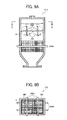
- FIGS. 9A and 9B a description is now given of such arrangement of rotary shafts in a developer container 51U of the development device 5Y (depicted in FIG. 2 ) according to yet another exemplary embodiment.
- FIG. 9A is a sectional view of the developer container 51U.
- FIG. 9B is a top sectional view thereof seen in a direction Y in FIG. 9A .
- the developer container 51U includes paddles 200.
- the paddle 200 includes a rotary shaft 200A.
- the paddle 200 serves as an agitator.
- the rotary shafts 200A in one row (e.g., an upper row) extend perpendicular to the rotary shafts 200A in another row (e.g., a lower row) in a horizontal section perpendicular to the flow-down direction of the developer.
- the developer is circulated in the developer container 51U in a more complicated manner (e.g., in various directions), causing the toner particles to contact the carrier with improved frequency, thereby improving a charging ability of the developer.
- FIG. 10 is a schematic view of an outer agitator 72M1 as a first modification of the outer agitator 72.
- the outer agitator 72M1 includes holes 72B1.
- Modification of a number, a size, a shape, a position, and the like, of the hole 72B1 may improve an agitation efficiency of the developer and reduce stress on the developer.
- FIG. 11 is a schematic view of an outer agitator 72M2 as a second modification of the outer agitator 72 (depicted in FIG. 6 ).
- the outer agitator 72M2 includes a mesh 72B.
- the mesh 72B may have a net-like shape providing a large gap rate (e.g., a large opening area), so that toner particles and a carrier may be efficiently dispersed, thereby reducing the rotation speed of the outer agitator 72M2 and also reducing stress on the developer.
- a large gap rate e.g., a large opening area
- a size of a gap of the mesh 72B may be preferably large enough to allow the carrier to pass through and also large enough to allow toner particles to contact the carrier easily and smoothly.
- the carrier may not clog the mesh 72B.
- the mesh 72B may cope with various sizes of the carrier. For example, the carrier with an increased particle diameter may pass through the mesh 72B.
- Fig. 12 and 13 relate to an illustrating example which does not form part of the present invention.
- FIG. 12 is a schematic view of an outer agitator 72M3 as a third modification of the outer agitator 72 (depicted in FIG. 6 ).
- the outer agitator 72M3 includes a comb 72C.
- the developer may pass through a space between teeth of the comb 72C, thereby improving the dispersion efficiency of the developer.
- the dispersion efficiency of the developer depends on a size or a length of the teeth, or a distance between the adjacent teeth.
- the comb 72C may include a flexible material, so as to improve an efficiency of movement of the developer.
- FIG. 13 is a schematic view of an outer agitator 72M4 as a fourth modification of the outer agitator 72 (depicted in FIG. 6 ).
- the outer agitator 72M4 includes a brush 72D.
- the developer may pass through a space between bristles of the brush 72D.
- the brush 72D may have a significantly larger contact area in which the brush 72D contacts the developer than the holes 72B1 (depicted in FIG. 10 ), the mesh 72B (depicted in FIG. 11 ), and the comb 72C (depicted in FIG. 12 ) have, the toner particles may contact the carrier with increased frequency, thereby improving an efficiency of frictional charging of the toner particles.
- selection of a material of the brush 72D may improve the agitation efficiency of the developer as well as reduce the agitation stress on the developer, thereby efficiently charging the toner particles.
- use of the holes 72B1 (depicted in FIG. 10 ), the mesh 72B (depicted in FIG. 11 ), the comb 72C (depicted in FIG. 12 ), or the brush 72D (depicted in FIG. 13 ) may reduce contact resistance of the developer against the outer agitator 72M1 (depicted in FIG. 10 ), the outer agitator 72M2 (depicted in FIG. 11 ), the outer agitator 72M3 (depicted in FIG. 12 ), or the outer agitator 72M4 (depicted in FIG. 13 ), so as to reduce damage to the developer, thereby preventing degradation of the developer.
- an agitator (e.g., the outer agitator 72 depicted in FIG. 6 ) may include a hole (e.g., the hole 72B1 depicted in FIG. 10 ), a mesh (e.g., the mesh 72A depicted in FIG. 6 and the mesh 72B depicted in FIG. 11 ), a comb (e.g., the comb 72C depicted in FIG. 12 ), or a brush (e.g., the brush 72D depicted in FIG. 13 ).
- a hole e.g., the hole 72B1 depicted in FIG. 10
- a mesh e.g., the mesh 72A depicted in FIG. 6 and the mesh 72B depicted in FIG. 11
- a comb e.g., the comb 72C depicted in FIG. 12
- a brush e.g., the brush 72D depicted in FIG. 13
- it may include any member having a gap.
- a material of the carrier
Landscapes
- Physics & Mathematics (AREA)
- General Physics & Mathematics (AREA)
- Life Sciences & Earth Sciences (AREA)
- Engineering & Computer Science (AREA)
- Environmental & Geological Engineering (AREA)
- Sustainable Development (AREA)
- Dry Development In Electrophotography (AREA)
Claims (5)
- Entwicklungsvorrichtung (5Y), aufweisend:ein Entwicklungsglied (50), das konfiguriert ist, um ein elektrostatisches latentes Bild, das auf einer Bildtrageeinrichtung (1Y) eines latenten Bildes gebildet ist, zu entwickeln, und zwar mit einem Entwickler, der Toner und ein Trägermaterial enthält, um das elektrostatische latente Bild sichtbar zu machen; undein Zirkulationsglied (56), das konfiguriert ist, um den Entwickler zu empfangen bzw. aufzunehmen, der von dem Entwicklungsglied (50) ausgestoßen bzw. ausgebracht wird, und um den Entwickler zurück zu dem Entwicklungsglied (50) zu transportieren,
aufweisend einen Behälter (51), der stromaufwärts von dem Entwicklungsglied (50) in einer Transportrichtung von dem Entwickler zur Verfügung gestellt wird, um den Entwickler zu speichern bzw. unterzubringen,
wobei der Behälter (51) eine Rühreinrichtung (80) aufweist, die innerhalb des Behälters (51) zur Verfügung gestellt wird und die konfiguriert ist, um den Entwickler und neuen bzw. unverbrauchten Toner, der zu dem Behälter (51) zugeführt wird, zu rühren und zu mischen,
wobei die Rühreinrichtung (80) eine drehbare Welle (80A) aufweist, welche vertikal in dem Entwicklerbehälter (51) eingefügt ist,
und wobei die drehbare Welle (80A) von der Rühreinrichtung (80) eine Längsrichtung in einer vertikalen Richtung hat,
dadurch gekennzeichnet, dass die Rühreinrichtung (80) ferner eine Mehrzahl von Schaufeln (80B) aufweist, wobei jede Schaufel Löcher (80B1) aufweist, die in einer Richtung senkrecht zu der Längsrichtung angeordnet sind, so dass der Entwickler durch die Löcher hindurchgeht, um den neuen bzw. unverbrauchten Toner und den Entwickler zu mischen, um in dem Behälter (51) gerührt zu werden, wobei die Schaufeln (80B) umfänglich um die drehbare Welle (80A) herum zur Verfügung gestellt werden. - Entwicklungsvorrichtung gemäß Anspruch 1,
wobei der Behälter (51) einen trichterförmigen Abschnitt von kleiner werdendem Druckmesser hat, der sich in Richtung eines unteren Teils bzw. Bodens von dem Behälter (51) erstreckt und einen Einlass, der in einem oberen Teil davon zur Verfügung gestellt wird, und einen Auslass (50A) aufweist, der in einem unteren Teil davon zur Verfügung gestellt wird,
wobei die Rühreinrichtung (80) den Entwickler rührt, der von dem Einlass von dem Behälter (51) zugeführt wird, um Bewegung von dem Entwickler zu behindern bzw. zu hemmen, der durch Schwerkraft abwärts bzw. nach unten strömt. - Entwicklungsvorrichtung gemäß Anspruch 1 oder 2, wobei die Rühreinrichtung (80) den Entwickler in einer Richtung rührt, die senkrecht zu einer Hinabströmungsrichtung von dem Entwickler ist.
- Entwicklungsvorrichtung gemäß irgendeinem der Ansprüche 1 bis 3, ferner aufweisend:eine zweite Rühreinrichtung (71), die in einer inneren Seite von der ersten Rühreinrichtung angeordnet ist und die konfiguriert ist, um sich um einen Mittelteil bzw. Zentralteil von dem Behälter (51) zu drehen,wobei die zweite Rühreinrichtung (71) einen Schneckenförderer aufweist, der eine drehbare Welle hat, die sich in einer vertikalen Richtung in dem Mittelteil bzw. Zentralteil von dem Behälter (51) erstreckt,wobei die erste Rühreinrichtung (72) in einer äußeren Seite von dem Schneckenförderer von der zweiten Rühreinrichtung angeordnet ist und die Schaufeln (72A) aufweist, die um die drehbare Welle von dem Schneckenförderer drehbar sind.
- Bilderzeugungsapparat, gekennzeichnet durch Aufweisen:einer Trageinrichtung (1Y) eines latenten Bildes, die konfiguriert ist, um ein elektrostatisches latentes Bild zu tragen; undeiner Entwicklungsvorrichtung (5Y) gemäß den Ansprüchen 1 bis 4.
Applications Claiming Priority (1)
| Application Number | Priority Date | Filing Date | Title |
|---|---|---|---|
| JP2007145444A JP5277566B2 (ja) | 2007-05-31 | 2007-05-31 | 現像装置および画像形成装置 |
Publications (2)
| Publication Number | Publication Date |
|---|---|
| EP1998232A1 EP1998232A1 (de) | 2008-12-03 |
| EP1998232B1 true EP1998232B1 (de) | 2015-04-15 |
Family
ID=39608156
Family Applications (1)
| Application Number | Title | Priority Date | Filing Date |
|---|---|---|---|
| EP08157292.7A Ceased EP1998232B1 (de) | 2007-05-31 | 2008-05-30 | Entwicklungsvorrichtung und Bilderzeugungsvorrichtung |
Country Status (3)
| Country | Link |
|---|---|
| US (2) | US8014703B2 (de) |
| EP (1) | EP1998232B1 (de) |
| JP (1) | JP5277566B2 (de) |
Families Citing this family (23)
| Publication number | Priority date | Publication date | Assignee | Title |
|---|---|---|---|---|
| JP5277566B2 (ja) * | 2007-05-31 | 2013-08-28 | 株式会社リコー | 現像装置および画像形成装置 |
| JP4999166B2 (ja) * | 2007-06-01 | 2012-08-15 | 株式会社リコー | 現像装置および画像形成装置 |
| US8135314B2 (en) * | 2007-12-26 | 2012-03-13 | Ricoh Company, Limited | Developing device, process cartridge, and image forming apparatus, method of developing latent image |
| JP5168631B2 (ja) * | 2008-03-11 | 2013-03-21 | 株式会社リコー | 現像装置及び画像形成装置 |
| US8000638B2 (en) | 2008-06-24 | 2011-08-16 | Ricoh Company, Ltd. | Developing device using two-component developing agent and image forming apparatus provided with same |
| JP5321112B2 (ja) * | 2008-09-11 | 2013-10-23 | 株式会社リコー | 現像装置及び画像形成装置 |
| JP5463654B2 (ja) | 2008-11-20 | 2014-04-09 | 株式会社リコー | 現像装置および画像形成装置 |
| JP2010134265A (ja) * | 2008-12-05 | 2010-06-17 | Ricoh Co Ltd | 現像装置及び画像形成装置 |
| JP5445168B2 (ja) | 2010-01-25 | 2014-03-19 | 株式会社リコー | 画像形成装置 |
| JP5447036B2 (ja) * | 2010-03-16 | 2014-03-19 | 株式会社リコー | 現像装置および画像形成装置 |
| JP2011196450A (ja) | 2010-03-18 | 2011-10-06 | Ricoh Co Ltd | 駆動装置および画像形成装置 |
| JP2012037738A (ja) * | 2010-08-06 | 2012-02-23 | Ricoh Co Ltd | 現像装置及びプロセスカートリッジ及び画像形成装置 |
| JP5065459B2 (ja) * | 2010-08-23 | 2012-10-31 | シャープ株式会社 | 現像装置およびそれを備えた画像形成装置 |
| JP5811442B2 (ja) | 2010-08-26 | 2015-11-11 | 株式会社リコー | 現像装置及び画像形成装置 |
| JP5569260B2 (ja) | 2010-08-27 | 2014-08-13 | 株式会社リコー | 現像装置および画像形成装置 |
| JP2012078786A (ja) | 2010-09-08 | 2012-04-19 | Ricoh Co Ltd | 現像装置および画像形成装置 |
| US8688012B2 (en) | 2010-11-04 | 2014-04-01 | Ricoh Company, Ltd. | Developing device and image forming apparatus |
| JP5742008B2 (ja) | 2011-03-10 | 2015-07-01 | 株式会社リコー | 現像装置および画像形成装置 |
| JP6132182B2 (ja) * | 2012-12-18 | 2017-05-24 | 株式会社リコー | 廃トナー搬送装置及びこれを用いた画像形成装置 |
| JP6394351B2 (ja) | 2014-03-17 | 2018-09-26 | 株式会社リコー | 粉体収容容器及び画像形成装置 |
| JP2016006471A (ja) | 2014-05-30 | 2016-01-14 | 株式会社リコー | 画像形成装置 |
| US10474061B2 (en) * | 2018-02-23 | 2019-11-12 | Lexmark International, Inc. | Reduced capacity toner cartridge for an electrophotographic image forming device having an isolated toner volume surrounding an auger of the toner cartridge |
| JP7548070B2 (ja) | 2021-03-08 | 2024-09-10 | 株式会社リコー | トナー残量検出装置及び画像形成装置 |
Citations (2)
| Publication number | Priority date | Publication date | Assignee | Title |
|---|---|---|---|---|
| US5561506A (en) * | 1994-02-16 | 1996-10-01 | Ricoh Company, Ltd. | Developing device for an image forming apparatus having a developer normalizing mechanism independent of a developing mechanism |
| US5835827A (en) * | 1996-07-04 | 1998-11-10 | Mita Industrial Co., Ltd. | Stirrer and toner cartridge equipped with the stirrer |
Family Cites Families (39)
| Publication number | Priority date | Publication date | Assignee | Title |
|---|---|---|---|---|
| US5249019A (en) * | 1989-11-29 | 1993-09-28 | Mita Industrial Co., Ltd. | Feed roller for mixing and feeding a powder |
| JP2853373B2 (ja) | 1991-05-21 | 1999-02-03 | 富士ゼロックス株式会社 | 一成分現像装置 |
| JPH05165321A (ja) * | 1991-12-18 | 1993-07-02 | Fujitsu Ltd | 現像装置 |
| JPH0635314A (ja) | 1992-07-15 | 1994-02-10 | Ricoh Co Ltd | 現像装置 |
| JPH07230241A (ja) * | 1993-12-22 | 1995-08-29 | Canon Inc | 画像形成装置 |
| JPH07219324A (ja) * | 1994-01-31 | 1995-08-18 | Ricoh Co Ltd | 現像装置 |
| JPH07219347A (ja) | 1994-02-04 | 1995-08-18 | Ricoh Co Ltd | 現像装置 |
| JP3734096B2 (ja) * | 1994-10-20 | 2006-01-11 | 株式会社リコー | 画像形成装置 |
| JP3483322B2 (ja) * | 1994-11-04 | 2004-01-06 | 株式会社リコー | 現像装置 |
| JPH1063081A (ja) | 1996-08-13 | 1998-03-06 | Fuji Xerox Co Ltd | 現像装置 |
| DE19742668A1 (de) | 1997-09-26 | 1999-04-22 | Oce Printing Systems Gmbh | Entwicklerstation mit Schaufelwalzenanordnung zur Querdurchmischung des Entwicklergemisches |
| JPH11202708A (ja) | 1998-01-08 | 1999-07-30 | Matsushita Electric Ind Co Ltd | 画像形成装置 |
| JP2001188408A (ja) | 1999-12-28 | 2001-07-10 | Kyocera Mita Corp | 二成分系現像剤用現像装置 |
| JP3977600B2 (ja) | 2001-02-16 | 2007-09-19 | シャープ株式会社 | 現像カートリッジ |
| US6567635B2 (en) | 2001-09-20 | 2003-05-20 | Nexpress Solutions Llc | Apparatus and method for agitating toner in a container to facilitate toner dispensing in an electrostatographic printer |
| JP4095875B2 (ja) | 2001-10-30 | 2008-06-04 | 株式会社リコー | 現像剤収納容器及び画像形成装置 |
| US6882816B2 (en) | 2002-02-19 | 2005-04-19 | Matsushita Electric Industrial Co., Ltd. | Developing device with developer circulating path |
| JP4225135B2 (ja) * | 2003-06-26 | 2009-02-18 | コニカミノルタビジネステクノロジーズ株式会社 | 現像装置および画像形成装置 |
| JP3846465B2 (ja) | 2003-08-25 | 2006-11-15 | コニカミノルタビジネステクノロジーズ株式会社 | 現像装置及び画像形成装置 |
| KR100547149B1 (ko) * | 2003-10-20 | 2006-01-26 | 삼성전자주식회사 | 전자사진방식 화상형성장치의 토너 카트리지 |
| JP4276935B2 (ja) | 2003-12-26 | 2009-06-10 | 株式会社リコー | 画像形成装置 |
| JP4614332B2 (ja) | 2004-06-18 | 2011-01-19 | 株式会社リコー | 現像剤劣化検知方法、現像剤劣化検知装置、現像装置、画像形成装置及び画像形成方法 |
| JP4344668B2 (ja) | 2004-09-21 | 2009-10-14 | 株式会社 伊藤園 | 水性液の硝酸除去方法及び飲料の製造方法 |
| JP2006163292A (ja) | 2004-12-10 | 2006-06-22 | Ricoh Co Ltd | 現像装置 |
| JP2006276615A (ja) * | 2005-03-30 | 2006-10-12 | Kyocera Mita Corp | トナー供給装置 |
| JP2007057743A (ja) * | 2005-08-24 | 2007-03-08 | Fuji Xerox Co Ltd | 静電潜像現像用キャリア及び静電潜像現像用現像剤及び現像装置 |
| JP4737541B2 (ja) | 2005-09-05 | 2011-08-03 | 株式会社リコー | 現像剤搬送装置及び画像形成装置 |
| JP4889008B2 (ja) | 2005-09-07 | 2012-02-29 | 株式会社リコー | 現像剤搬送装置及び画像形成装置 |
| JP2007193301A (ja) | 2005-12-20 | 2007-08-02 | Ricoh Co Ltd | 現像装置及び画像形成装置 |
| US7792472B2 (en) * | 2006-01-13 | 2010-09-07 | Ricoh Company, Ltd. | Developing apparatus and image forming apparatus using same |
| JP4853963B2 (ja) | 2006-05-15 | 2012-01-11 | 株式会社リコー | 現像装置、プロセスカートリッジ、及び、画像形成装置 |
| US7835653B2 (en) | 2006-05-25 | 2010-11-16 | Ricoh Company, Limited | Developing device and image forming apparatus |
| JP5277566B2 (ja) * | 2007-05-31 | 2013-08-28 | 株式会社リコー | 現像装置および画像形成装置 |
| JP4999166B2 (ja) | 2007-06-01 | 2012-08-15 | 株式会社リコー | 現像装置および画像形成装置 |
| US8000638B2 (en) | 2008-06-24 | 2011-08-16 | Ricoh Company, Ltd. | Developing device using two-component developing agent and image forming apparatus provided with same |
| JP5463654B2 (ja) | 2008-11-20 | 2014-04-09 | 株式会社リコー | 現像装置および画像形成装置 |
| JP2010134265A (ja) | 2008-12-05 | 2010-06-17 | Ricoh Co Ltd | 現像装置及び画像形成装置 |
| JP5445168B2 (ja) | 2010-01-25 | 2014-03-19 | 株式会社リコー | 画像形成装置 |
| JP5447036B2 (ja) | 2010-03-16 | 2014-03-19 | 株式会社リコー | 現像装置および画像形成装置 |
-
2007
- 2007-05-31 JP JP2007145444A patent/JP5277566B2/ja not_active Expired - Fee Related
-
2008
- 2008-05-30 EP EP08157292.7A patent/EP1998232B1/de not_active Ceased
- 2008-05-30 US US12/130,092 patent/US8014703B2/en not_active Expired - Fee Related
-
2011
- 2011-07-15 US US13/183,472 patent/US8280281B2/en not_active Expired - Fee Related
Patent Citations (2)
| Publication number | Priority date | Publication date | Assignee | Title |
|---|---|---|---|---|
| US5561506A (en) * | 1994-02-16 | 1996-10-01 | Ricoh Company, Ltd. | Developing device for an image forming apparatus having a developer normalizing mechanism independent of a developing mechanism |
| US5835827A (en) * | 1996-07-04 | 1998-11-10 | Mita Industrial Co., Ltd. | Stirrer and toner cartridge equipped with the stirrer |
Also Published As
| Publication number | Publication date |
|---|---|
| JP2008299107A (ja) | 2008-12-11 |
| US8014703B2 (en) | 2011-09-06 |
| JP5277566B2 (ja) | 2013-08-28 |
| US20080298845A1 (en) | 2008-12-04 |
| US8280281B2 (en) | 2012-10-02 |
| EP1998232A1 (de) | 2008-12-03 |
| US20110268478A1 (en) | 2011-11-03 |
Similar Documents
| Publication | Publication Date | Title |
|---|---|---|
| US8014703B2 (en) | Development device and image forming apparatus | |
| US8036576B2 (en) | Developing device including a stirring mechanism for a two-component developer and image forming apparatus including same | |
| JP5660312B2 (ja) | 現像剤搬送装置、現像剤収容器、現像装置、プロセスユニット及び画像形成装置 | |
| JP5820828B2 (ja) | 現像装置およびこれを備えた画像形成装置 | |
| CN101887226A (zh) | 显影装置和使用该显影装置的图像形成设备 | |
| US20110229207A1 (en) | Developing device and image forming apparatus | |
| JP4963980B2 (ja) | 現像装置、プロセスカートリッジ、及び、画像形成装置 | |
| US20100226688A1 (en) | Developing device, process cartridge and image forming apparatus | |
| JP2010014890A (ja) | 現像装置、プロセスカートリッジ、及び画像形成装置 | |
| JP2008257213A (ja) | 現像装置、プロセスカートリッジ及び画像形成装置 | |
| KR101580841B1 (ko) | 현상기 및 이를 채용한 전자사진방식 화상형성장치 | |
| JP2009116195A (ja) | 画像形成装置 | |
| JP2021086020A (ja) | 現像室用通気路を有する画像形成システム | |
| JP5284002B2 (ja) | 現像装置及びこれを用いる画像形成装置 | |
| JP2009168954A (ja) | 現像装置、画像形成装置 | |
| EP1434109B1 (de) | Entwicklungsgerät mit zwei Dosierklingen | |
| US8995883B2 (en) | Developing device and image forming apparatus including same | |
| JPH05346735A (ja) | 現像装置 | |
| JP2014123065A (ja) | 粉体収容容器および画像形成装置 | |
| JP5165493B2 (ja) | 現像装置及びこれを用いる画像形成装置 | |
| JPH063951A (ja) | 現像装置 | |
| CN102129191A (zh) | 显影装置以及包括显影装置的图像形成设备 | |
| JP4331665B2 (ja) | 現像装置 | |
| JP4504776B2 (ja) | 現像装置及び画像形成装置 | |
| JPH0619309A (ja) | 現像装置 |
Legal Events
| Date | Code | Title | Description |
|---|---|---|---|
| PUAI | Public reference made under article 153(3) epc to a published international application that has entered the european phase |
Free format text: ORIGINAL CODE: 0009012 |
|
| AK | Designated contracting states |
Kind code of ref document: A1 Designated state(s): AT BE BG CH CY CZ DE DK EE ES FI FR GB GR HR HU IE IS IT LI LT LU LV MC MT NL NO PL PT RO SE SI SK TR |
|
| AX | Request for extension of the european patent |
Extension state: AL BA MK RS |
|
| 17P | Request for examination filed |
Effective date: 20090209 |
|
| AKX | Designation fees paid |
Designated state(s): DE FR GB |
|
| 17Q | First examination report despatched |
Effective date: 20110310 |
|
| GRAP | Despatch of communication of intention to grant a patent |
Free format text: ORIGINAL CODE: EPIDOSNIGR1 |
|
| INTG | Intention to grant announced |
Effective date: 20141128 |
|
| GRAS | Grant fee paid |
Free format text: ORIGINAL CODE: EPIDOSNIGR3 |
|
| GRAA | (expected) grant |
Free format text: ORIGINAL CODE: 0009210 |
|
| AK | Designated contracting states |
Kind code of ref document: B1 Designated state(s): DE FR GB |
|
| REG | Reference to a national code |
Ref country code: GB Ref legal event code: FG4D |
|
| REG | Reference to a national code |
Ref country code: DE Ref legal event code: R096 Ref document number: 602008037653 Country of ref document: DE Effective date: 20150528 |
|
| REG | Reference to a national code |
Ref country code: DE Ref legal event code: R097 Ref document number: 602008037653 Country of ref document: DE |
|
| PLBE | No opposition filed within time limit |
Free format text: ORIGINAL CODE: 0009261 |
|
| STAA | Information on the status of an ep patent application or granted ep patent |
Free format text: STATUS: NO OPPOSITION FILED WITHIN TIME LIMIT |
|
| 26N | No opposition filed |
Effective date: 20160118 |
|
| REG | Reference to a national code |
Ref country code: FR Ref legal event code: PLFP Year of fee payment: 9 |
|
| REG | Reference to a national code |
Ref country code: FR Ref legal event code: PLFP Year of fee payment: 10 |
|
| REG | Reference to a national code |
Ref country code: FR Ref legal event code: PLFP Year of fee payment: 11 |
|
| PGFP | Annual fee paid to national office [announced via postgrant information from national office to epo] |
Ref country code: DE Payment date: 20180522 Year of fee payment: 11 |
|
| PGFP | Annual fee paid to national office [announced via postgrant information from national office to epo] |
Ref country code: FR Payment date: 20180522 Year of fee payment: 11 |
|
| PGFP | Annual fee paid to national office [announced via postgrant information from national office to epo] |
Ref country code: GB Payment date: 20180518 Year of fee payment: 11 |
|
| REG | Reference to a national code |
Ref country code: DE Ref legal event code: R119 Ref document number: 602008037653 Country of ref document: DE |
|
| GBPC | Gb: european patent ceased through non-payment of renewal fee |
Effective date: 20190530 |
|
| PG25 | Lapsed in a contracting state [announced via postgrant information from national office to epo] |
Ref country code: GB Free format text: LAPSE BECAUSE OF NON-PAYMENT OF DUE FEES Effective date: 20190530 Ref country code: DE Free format text: LAPSE BECAUSE OF NON-PAYMENT OF DUE FEES Effective date: 20191203 |
|
| PG25 | Lapsed in a contracting state [announced via postgrant information from national office to epo] |
Ref country code: FR Free format text: LAPSE BECAUSE OF NON-PAYMENT OF DUE FEES Effective date: 20190531 |