EP1987976B1 - Method of assembling of a modular ratchet cap - Google Patents
Method of assembling of a modular ratchet cap Download PDFInfo
- Publication number
- EP1987976B1 EP1987976B1 EP20080075670 EP08075670A EP1987976B1 EP 1987976 B1 EP1987976 B1 EP 1987976B1 EP 20080075670 EP20080075670 EP 20080075670 EP 08075670 A EP08075670 A EP 08075670A EP 1987976 B1 EP1987976 B1 EP 1987976B1
- Authority
- EP
- European Patent Office
- Prior art keywords
- cap assembly
- cap
- assembly
- threaded portion
- outer cover
- Prior art date
- Legal status (The legal status is an assumption and is not a legal conclusion. Google has not performed a legal analysis and makes no representation as to the accuracy of the status listed.)
- Active
Links
Images


Classifications
-
- B—PERFORMING OPERATIONS; TRANSPORTING
- B60—VEHICLES IN GENERAL
- B60K—ARRANGEMENT OR MOUNTING OF PROPULSION UNITS OR OF TRANSMISSIONS IN VEHICLES; ARRANGEMENT OR MOUNTING OF PLURAL DIVERSE PRIME-MOVERS IN VEHICLES; AUXILIARY DRIVES FOR VEHICLES; INSTRUMENTATION OR DASHBOARDS FOR VEHICLES; ARRANGEMENTS IN CONNECTION WITH COOLING, AIR INTAKE, GAS EXHAUST OR FUEL SUPPLY OF PROPULSION UNITS IN VEHICLES
- B60K15/00—Arrangement in connection with fuel supply of combustion engines or other fuel consuming energy converters, e.g. fuel cells; Mounting or construction of fuel tanks
- B60K15/03—Fuel tanks
- B60K15/04—Tank inlets
- B60K15/0406—Filler caps for fuel tanks
- B60K15/0409—Provided with a lock
-
- F—MECHANICAL ENGINEERING; LIGHTING; HEATING; WEAPONS; BLASTING
- F16—ENGINEERING ELEMENTS AND UNITS; GENERAL MEASURES FOR PRODUCING AND MAINTAINING EFFECTIVE FUNCTIONING OF MACHINES OR INSTALLATIONS; THERMAL INSULATION IN GENERAL
- F16K—VALVES; TAPS; COCKS; ACTUATING-FLOATS; DEVICES FOR VENTING OR AERATING
- F16K24/00—Devices, e.g. valves, for venting or aerating enclosures
- F16K24/04—Devices, e.g. valves, for venting or aerating enclosures for venting only
-
- Y—GENERAL TAGGING OF NEW TECHNOLOGICAL DEVELOPMENTS; GENERAL TAGGING OF CROSS-SECTIONAL TECHNOLOGIES SPANNING OVER SEVERAL SECTIONS OF THE IPC; TECHNICAL SUBJECTS COVERED BY FORMER USPC CROSS-REFERENCE ART COLLECTIONS [XRACs] AND DIGESTS
- Y10—TECHNICAL SUBJECTS COVERED BY FORMER USPC
- Y10T—TECHNICAL SUBJECTS COVERED BY FORMER US CLASSIFICATION
- Y10T137/00—Fluid handling
- Y10T137/2931—Diverse fluid containing pressure systems
- Y10T137/3003—Fluid separating traps or vents
- Y10T137/3084—Discriminating outlet for gas
- Y10T137/309—Fluid sensing valve
- Y10T137/3099—Float responsive
-
- Y—GENERAL TAGGING OF NEW TECHNOLOGICAL DEVELOPMENTS; GENERAL TAGGING OF CROSS-SECTIONAL TECHNOLOGIES SPANNING OVER SEVERAL SECTIONS OF THE IPC; TECHNICAL SUBJECTS COVERED BY FORMER USPC CROSS-REFERENCE ART COLLECTIONS [XRACs] AND DIGESTS
- Y10—TECHNICAL SUBJECTS COVERED BY FORMER USPC
- Y10T—TECHNICAL SUBJECTS COVERED BY FORMER US CLASSIFICATION
- Y10T137/00—Fluid handling
- Y10T137/8593—Systems
- Y10T137/86292—System with plural openings, one a gas vent or access opening
- Y10T137/86324—Tank with gas vent and inlet or outlet
- Y10T137/86332—Vent and inlet or outlet in unitary mounting
-
- Y—GENERAL TAGGING OF NEW TECHNOLOGICAL DEVELOPMENTS; GENERAL TAGGING OF CROSS-SECTIONAL TECHNOLOGIES SPANNING OVER SEVERAL SECTIONS OF THE IPC; TECHNICAL SUBJECTS COVERED BY FORMER USPC CROSS-REFERENCE ART COLLECTIONS [XRACs] AND DIGESTS
- Y10—TECHNICAL SUBJECTS COVERED BY FORMER USPC
- Y10T—TECHNICAL SUBJECTS COVERED BY FORMER US CLASSIFICATION
- Y10T29/00—Metal working
- Y10T29/49—Method of mechanical manufacture
- Y10T29/49826—Assembling or joining
- Y10T29/49863—Assembling or joining with prestressing of part
- Y10T29/49876—Assembling or joining with prestressing of part by snap fit
-
- Y—GENERAL TAGGING OF NEW TECHNOLOGICAL DEVELOPMENTS; GENERAL TAGGING OF CROSS-SECTIONAL TECHNOLOGIES SPANNING OVER SEVERAL SECTIONS OF THE IPC; TECHNICAL SUBJECTS COVERED BY FORMER USPC CROSS-REFERENCE ART COLLECTIONS [XRACs] AND DIGESTS
- Y10—TECHNICAL SUBJECTS COVERED BY FORMER USPC
- Y10T—TECHNICAL SUBJECTS COVERED BY FORMER US CLASSIFICATION
- Y10T29/00—Metal working
- Y10T29/49—Method of mechanical manufacture
- Y10T29/49826—Assembling or joining
- Y10T29/49904—Assembling a subassembly, then assembling with a second subassembly
-
- Y—GENERAL TAGGING OF NEW TECHNOLOGICAL DEVELOPMENTS; GENERAL TAGGING OF CROSS-SECTIONAL TECHNOLOGIES SPANNING OVER SEVERAL SECTIONS OF THE IPC; TECHNICAL SUBJECTS COVERED BY FORMER USPC CROSS-REFERENCE ART COLLECTIONS [XRACs] AND DIGESTS
- Y10—TECHNICAL SUBJECTS COVERED BY FORMER USPC
- Y10T—TECHNICAL SUBJECTS COVERED BY FORMER US CLASSIFICATION
- Y10T29/00—Metal working
- Y10T29/49—Method of mechanical manufacture
- Y10T29/49826—Assembling or joining
- Y10T29/49945—Assembling or joining by driven force fit
-
- Y—GENERAL TAGGING OF NEW TECHNOLOGICAL DEVELOPMENTS; GENERAL TAGGING OF CROSS-SECTIONAL TECHNOLOGIES SPANNING OVER SEVERAL SECTIONS OF THE IPC; TECHNICAL SUBJECTS COVERED BY FORMER USPC CROSS-REFERENCE ART COLLECTIONS [XRACs] AND DIGESTS
- Y10—TECHNICAL SUBJECTS COVERED BY FORMER USPC
- Y10T—TECHNICAL SUBJECTS COVERED BY FORMER US CLASSIFICATION
- Y10T29/00—Metal working
- Y10T29/49—Method of mechanical manufacture
- Y10T29/49826—Assembling or joining
- Y10T29/49947—Assembling or joining by applying separate fastener
- Y10T29/49959—Nonresilient fastener
-
- Y—GENERAL TAGGING OF NEW TECHNOLOGICAL DEVELOPMENTS; GENERAL TAGGING OF CROSS-SECTIONAL TECHNOLOGIES SPANNING OVER SEVERAL SECTIONS OF THE IPC; TECHNICAL SUBJECTS COVERED BY FORMER USPC CROSS-REFERENCE ART COLLECTIONS [XRACs] AND DIGESTS
- Y10—TECHNICAL SUBJECTS COVERED BY FORMER USPC
- Y10T—TECHNICAL SUBJECTS COVERED BY FORMER US CLASSIFICATION
- Y10T70/00—Locks
- Y10T70/50—Special application
- Y10T70/5093—For closures
- Y10T70/554—Cover, lid, cap, encasing shield
- Y10T70/5562—Removable
- Y10T70/5571—Freely movable when locked
-
- Y—GENERAL TAGGING OF NEW TECHNOLOGICAL DEVELOPMENTS; GENERAL TAGGING OF CROSS-SECTIONAL TECHNOLOGIES SPANNING OVER SEVERAL SECTIONS OF THE IPC; TECHNICAL SUBJECTS COVERED BY FORMER USPC CROSS-REFERENCE ART COLLECTIONS [XRACs] AND DIGESTS
- Y10—TECHNICAL SUBJECTS COVERED BY FORMER USPC
- Y10T—TECHNICAL SUBJECTS COVERED BY FORMER US CLASSIFICATION
- Y10T70/00—Locks
- Y10T70/50—Special application
- Y10T70/5093—For closures
- Y10T70/554—Cover, lid, cap, encasing shield
- Y10T70/5562—Removable
- Y10T70/5575—Directly seating
- Y10T70/558—Cover-carried lock
-
- Y—GENERAL TAGGING OF NEW TECHNOLOGICAL DEVELOPMENTS; GENERAL TAGGING OF CROSS-SECTIONAL TECHNOLOGIES SPANNING OVER SEVERAL SECTIONS OF THE IPC; TECHNICAL SUBJECTS COVERED BY FORMER USPC CROSS-REFERENCE ART COLLECTIONS [XRACs] AND DIGESTS
- Y10—TECHNICAL SUBJECTS COVERED BY FORMER USPC
- Y10T—TECHNICAL SUBJECTS COVERED BY FORMER US CLASSIFICATION
- Y10T70/00—Locks
- Y10T70/50—Special application
- Y10T70/5093—For closures
- Y10T70/554—Cover, lid, cap, encasing shield
- Y10T70/5562—Removable
- Y10T70/5593—Movably seating
- Y10T70/5597—Cover-carried lock
- Y10T70/5602—Dead bolt
Definitions
- the present invention relates to a method of assembling caps for closing respective openings, such as a filling tube of a fuel tank and, more particularly the invention relates to modular cap assemblies.
- a vehicle fuel tank filler neck including the features of the preamble of claim 1 is disclosed in WO00/20292 .
- Another known vehicle fuel tank filler cap is disclosed in EP 1574381 .
- a method of assembling caps comprising providing a first outer cover the first outer cover having a first characteristic wherein the first characteristic, includes at least one of a color, a symbol, and printed indicia individualized for a first particular application to which the first cap assembly mounts providing a first inner member, having engaging threads formed thereon; and coupling the first outer cover with a first one of a number of identical inner members of a first cap assembly by snap engagement; , the method characterized by: providing a second inner member identical to the first inner member, having engaging threads formed thereon; providing a second outer cover , the second outer cover having a second characteristic different from the first characteristic wherein the second characteristic includes at least one of a color, a symbol, and printed indicia individualized for a second particular application to which the second cap assembly mounts; coupling the second outer cover with a second one of the number of identical inner members of a second cap assembly by snap engagement, and wherein the first outer cover includes a first detach
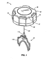
- FIG. 1 is a perspective view of a first modular ratchet cap construction with a non-vented inner body which may be modified and assembled in accordance with the present invention
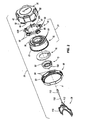
- FIG. 2 is an exploded assembly view of the cap of FIG. 1 ;
- FIG. 3 is a top view of the cap of FIG. 1 ;
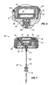
- FIG. 4 is a first cross-sectional view of the cap of FIG. 1 , taken along line 4-4 of FIG. 3 ;
- FIG. 5 is a first detail view of mating portions of the cap as shown in FIG. 4 ;
- FIG. 6 is a second detail view of additional mating portions of the cap as shown in FIG. 4 ;
- FIG. 7 is a second cross-sectional view of the cap of FIG. 1 , taken along line 7-7 of FIG. 3 ;
- FIG. 8 is a vented inner body for optional direct replacement of the non-vented inner body shown in at least FIGS. 2 , 4 , 6, and 7 ;
- FIG. 9 is a perspective view of a second modular ratchet cap construction having a first type of vent module and which may be modified and assembled in accordance with the present invention.
- FIG. 10 is an exploded assembly view of the cap of FIG. 9 ;
- FIG. 11 is a cross-sectional view of the cap of FIG. 9 , taken along line 11-1 of FIG. 9 ;
- FIG. 17 is an exploded assembly view of a third modular ratchet cap construction having a second type of vent module and which may be modified and assembled in accordance with the present invention ;
- FIG. 13 is a cross-sectional view of the cap of FIG. 12 , taken along line 13-13 of FIG. 12 ;
- FIG. 14 is an exploded assembly view of a fourth modular ratchet cap construction having a third type of vent module
- FIG. 15 is a cross-sectional view of the cap of FIG. 14 , taken along line 15-15 of FIG. 14 ;
- FIG. 16 is a top view of an alternate pawl member for optional direct replacement of the pawl members shown in at least FIGS. 9-15 ;
- FIG. 17 is a top view of an alternate cover portion for optional direct replacement of the cover portions shown in at least FIGS. 9-15 .
- a cap assembly generally includes components which are common to multiple cap configurations and which are used with substitutable components to provide a desired cap configuration (e.g., ratchet cap, locking cap, cap with vent, cap with carbon canister, cap with tether (of various lengths), combinations of one or more of such components, etc.), a desired cap size (e,g., for use with a given size threaded opening with or without such additional substitutalale components), a desired cap appearance (e.g., color(s) to meet end operator requirements, various indicators on cap components, etc.), etc.
- a desired cap configuration e.g., ratchet cap, locking cap, cap with vent, cap with carbon canister, cap with tether (of various lengths), combinations of one or more of such components, etc.
- a desired cap size e.g., for use with a given size threaded opening with or without such additional substitutalale components
- a desired cap appearance e.g., color(s) to meet end operator requirements,
- a cap assembly may include replaceable components such that if, for example, a component is worn or damaged (e.g., a ratchet assembly, a locking mechanism, a seal/gasket, etc.), that component may be easily replaced (by the operator, a service center, the manufacturer, etc.) without requiring replacement of the entire cap assembly, or necessarily any of the other components thereof.
- a component e.g., a ratchet assembly, a locking mechanism, a seal/gasket, etc.
- that component may be easily replaced (by the operator, a service center, the manufacturer, etc.) without requiring replacement of the entire cap assembly, or necessarily any of the other components thereof.
- a first modular cap assembly 20, which is shown in FIGS. 1-7 , and which may be modified in accordance with the present invention includes a ratchet assembly 24 and a tether assembly 28.
- the cap assembly 20 has a threaded portion 32 (i.e., "inner body"), which is able to be tightened onto a threaded opening up to a predetermined torque limit via the ratchet assembly 24.
- the ratchet assembly 24 limits the amount of torque in the tightening direction (e.g., when the cap assembly 20 is installed) transmitted to the threaded portion 32 to, for example, prevent over-tightening of the cap assembly 20, prevent damage to the threaded portion 32, provide audible and/or tactile feedback to the user that a sufficient level of torque (e.g., at or greater than a minimum retention torque) has been achieved, etc. Also, in the illustrated construction, the ratchet assembly 24 does not limit the amount of torque in the removal direction (e.g., when the cap assembly 20 is removed).
- the tether assembly 28 and the audible feedback of the ratchet qualify the cap assembly 20 in some embodiments for usage on vehicles as regulated by federal and state transportation and environmental laws (e.g., 2007 California state regulations and EPA 2010 regulations).
- the cap assembly 20 includes a cover portion 36, the threaded portion 32, and a pawl member 40 between the cover portion 36 and the threaded portion 32.
- the pawl member 40 is ring-shaped and is rotatable with the cover portion 36.
- the cover portion 36 includes recesses 42 and projections 44 (as perceived from the inside of the cover portion 36), and the pawl member 40 includes recesses 46 and projections 48 (see FIG. 2 ) that inter-engage with the recesses 42 and projections 44 of the cover portion 36 to provide the rotational connection therewith.
- the recesses 42 and the projections 44 on the cover portion 36 are incorporated into the appearance and/or function of the cover portion 36 (e.g., the outer profile or grasp surface of the cover portion 36 corresponds to the recesses 42 and the projections 44 on the inside of the cover portion 36).
- the pawl member 40 is positioned between a lower-facing surface 52 of the cover portion 36 and an upper-facing surface 56 of the threaded portion 32.
- Pawl arms 60 on the pawl member 40 engage pawl teeth 64 on the threaded portion 32 to transmit torque from the cover portion 36 through the pawl member 40 to the threaded portion 32. If the torque exceeds a predetermined torque amount (determined at least in part by the construction of the pawl arms 60), the pawl arms 60 flex and ride over the associated pawl teeth 64 such that the pawl member 40 and the cover portion 36 rotate relative to the threaded portion 32, and the torque-transmitting connection between the cover portion 36 to the threaded portion 32 is at least momentarily disengaged.
- the operator is able to loosen or un-twist the cap assembly 20 from the mating part (threaded opening, not shown) by gripping the outer profile of the cover portion 36 and twisting, for example, in a counter-clockwise direction. Under this torque load, the pawl member 40 is turned directly by the cover portion 36 through the five recesses 46 and protrusions 48 on the pawl member 40, which engage the recesses 42 and protrusions 44 of the cover portion 36.
- the pawl member 40 includes five pawl arms 60, which engage the pawl teeth 64 on the threaded portion 32.
- Each pawl arm 60 includes a resilient portion 60A and an engagement portion 60B.
- the engagement portions 60B of the pawl arms 60 are designed to engage definitely (i.e., without slip) under counter-clockwise rotation (e.g., when removing, the cap assembly 20 from the mating part) of the cover portion 36 by the operator.
- the engagement portions 60B of the pawl arms 60 are further designed to provide torque-limited ratchet action under clockwise rotation (e.g., when installing the cap assembly 20 on the mating part) of the cover portion 36 by the operator.
- the pawl arms 60 When the predetermined torque limit is reached during tightening of the cap assembly 20 by the operator, the pawl arms 60 will deflect from the pawl teeth 64 on the threaded portion 32 and allow the cover portion 36 to rotate relative to the threaded portion 32, alerting the user that an acceptable amount of torque (i.e., the predetermined torque limit) has been reached and protecting the threaded portion 32 from further tightening and potential damage from over-tightening.
- the pawl arms 60 deflect generally radially inward toward a central axis A of the cap assembly 20 such that the pawl arms 60, regardless of whether or not they are deflecting, are always lying in the same plane transverse to the central axis A.
- the cap assembly 20 also includes an assembly ring 68, a retainer 72, and a gasket 76.
- the retainer 72 snaps together with the threaded portion 32 and provides an attachment location for the tether assembly 28 (if the tether assembly 28 is desired for the particular cap assembly 20 as shown in at least FIGS. 1 , 2 , 4 , and 7 ).
- the assembly ring 68 is disposed at a lower end of the cover portion 36 and snaps together with the cover portion 36 in a position so as to provide a retaining surface 80 for fixing the threaded portion 32 axially with respect to the cover portion 32.
- a projection 81 (e.g., a radially outwardly extending annular wall) on the threaded portion 32 is engaged by the retaining surface 80.
- the cover portion 36 and the assembly ring 68 include respective mating portions 82 and 84 (see FIGS. 2 , 4, and 5 ) that snap together with each other, effectively coupling the cover portion 36 and the threaded portion 32 together.
- FIGS. 4-7 illustrate the cap assembly 20 in section views, showing the relationships between mating parts and the positioning of all the elements.
- the tether assembly 28 is snapped into an opening 88 in the retainer 72, and the retainer 72 holds the tether assembly 28 to the remainder of the cap assembly 20.
- the retainer 72 includes a projection 92 (e.g., an annular wall with a barbed edge) that snaps together with a projection 96 (e.g., an annular wall with a barbed edge) on the threaded portion 32.
- the tether assembly 28 is provided to retain the cap assembly 20 with an associated structure (e.g,, the mating part).
- the tether assembly 28 includes a tether 108 having a particular length, a pair of coupling portions 112, and an end portion 116 providing a particular type of interface with the mating part. The tether provides protection against losing the cap when removed and it also reminds the operator to re-secure the cap for example, after filling the tank, as the cap hangs off of the tank.
- the tether assembly 28 is substituted with another different tether assembly (e,g., having a different length and/or interface type, etc.).
- the tether assembly 28 may be replaced (e.g., if worn, damaged, etc.) or may be removed altogether without affecting the construction of the cap assembly 20 in any other way.
- alternate tether assemblies components of which may be substituted for the tether assembly 28 illustrated in at least FIGS. 1 , 2 , 4 , and 7 , are described and illustrated in U.S. Patent Nos. 4,872,587, issued October 10, 1989 ; 5,165,565, issued November 24, 1992 ; 5,320,240, issued June 14, 1994 ; and 6,109,467, issued August 29, 2000 .
- the cap assembly 20 is assembled primarily by snapping adjacent components together.
- each portion of the cap assembly 20 that snaps together with another portion has at least one engagement portion (e.g., projection, barb, etc.).
- An alternate substitute part may replace a similar part of the cap assembly 20 as long as it includes the requisite engagement portion.
- the threaded portion 32 is simply replaced by a similar-shaped part with an internal thread having a different size, pitch, etc. for conforming to industry standards or custom applications.
- the pawl member 40 and the gasket 76 which do not snap together with any other components, are also easily swapped for alternate substitute or replacement parts.
- a new pawl member may be introduced to the cap assembly 20 for providing a different torque limit.
- a new gasket may be introduced to the cap assembly 20, the new gasket having a different cross-sectional shape or being constructed of a different material than the original gasket 76, for example.
- the assembly ring 68 is simply replaced with different color assembly rings of the same or modified shape to match with color schemes of the associated enclosure or product (e.g., fuel tank, vehicle, etc.) or to provide an indication of the system (e.g., a designation of the contents of the associated enclosure or tank) by color-coding.
- the cover portion 36 is simply replaced with a substitute cover portion provided with symbols, printed indicia, etc. specific to a particular application and/or manufacturer as discussed further below.
- FIG. 8 illustrates a vented threaded portion 120 for direct substitution in place of the threaded portion 32, which is non vented.
- the vented threaded portion 120 includes a vent aperture 122 establishing a flow passage for air between the inside of the threaded portion 120 and the outside of the cap assembly 20 (i.e., air may come in or be expelled between the cover portion 36 and the threaded portion 120 adjacent the assembly ring 68.
- Other features of the threaded portion 120 remain as shown and described above.
- the threaded portion 120 may integrate a carbon canister.
- the cap assembly 20 may include structure which is similar to the canister structure described and illustrated in U.S. Patent Application Serial No. 11/058,063, filed February 14, 2005 , now Publication No. 2006/0011173 A1, published January 19, 2006 .
- the cap assembly 20 may include a looking mechanism operable between a locked condition, in which the cap is inhibited from being removed from the mating part, and an unlocked condition, in which the cap is removable from the mating part.
- the cover portion 36 is provided with an interchangeable top surface to allow internal features to protrude through (e.g., a portion of a locking mechanism, a vent, etc.).
- the interchangeable top surface may also be provided with varying graphics, indicia, etc., based on, for example, the tank contents, manufacturer/operator requirements, etc., or may provide other imprinted information for the operator.
- FIGS. 9-11 illustrate a second modular cap assembly 150 that may be modified in accordance with the invention.
- the cap assembly 150 includes a vent module 174 and a felt ring 178.
- the cover portion 154 snaps directly to the threaded portion 158 without a separate assembly ring.
- the cover portion 154 and the threaded portion 158 include respective projections 182 and 184 that engage one another to mate the cover and threaded portions 154 and 158.
- the felt ring 178 is positioned between the cover portion 154 and the threaded portion 158 along a flow passage between the outside of the cap assembly 150 and the inside of the threaded portion 158, allowing gases to pass through and preventing substantial passage of debris.
- the pawl member 162 is engaged with the cover portion 154 to prevent substantial relative rotation between the pawl member 162 and the cover portion 154. Respective engagement portions 188 and 192 are provided on the cover portion 154 and the pawl member 162.
- the pawl member 162 includes pawl arms 196, each including a resilient portion 200 and an engagement portion 204. The engagement portions 204 engage pawl teeth 208 on the threaded portion 158.
- the engagement between the pawl member 162 and the threaded portion 158 is substantially the same as that described above with reference to the cap assembly 20 in that the pawl member 162 provides only a limited amount of torque to be transmitted to the threaded portion 158 in the cap-installing direction and does not limit the torque in the cap-removing direction.
- the gasket 170 is held in place simply by engaging an annular wall 212 extending downnwardly from the threaded portion 158.
- the retainer 166 is therefore not necessary for positioning the gasket 170, but it provides the opening 216 for attaching the tether assembly 28 shown in at least FIGS. 1 , 2 , 4 , and 7 .
- an external tether 220 is assembled by snapping to the cover portion 154, which is provided with a mounting aperture 222.
- the retainer 166 includes a projection 224 (e.g., barbed annular wall) for snapping onto the vent module 174.
- the retainer 166 is structurally identical to the retainer 72 of the cap assembly 20, even though the retainer 72 engages directly with the threaded portion 32 and the gasket 76.
- the vent module 174 consists of a vent member 228 having a vent aperture 232 therein.
- the vent member 228 has an engagement portion 234 that engages a projection 236 on the threaded portion 158 such that the vent member 228 may be welded to the threaded portion 158. Alternately, the vent member 228 is simply snapped to the threaded portion 158, and in such a construction, an additional gasket may be provided.
- alternative welding techniques e.g., spin welding, ultrasonic welding, etc. may be employed for coupling plastic or polymeric materials.
- cap assembly 150 may be directly substituted by alternate components and/or simply replaced (e.g., if worn or damaged) without replacing the entire cap assembly 150.
- FIGS. 12 and 13 illustrate a third modular cap assembly 260 that may be modified in accordance with the present invention.
- the cap assembly 260 contains some identical components as those found in the second cap assembly 150. Such components are given identical reference numerals.
- the cap assembly 260 includes a cover portion 262, which does not feature the mounting aperture 222 found in the cover portion 154 of the cap assembly 150.
- the cap assembly 260 is shown with an internal-style tether assembly 263. Therefore, the cover portion 262 does not require means for mounting the external tether 220, but the cover portions 154 and 262 are easily interchanged if desired.
- the cover portion 154 may be provided in the cap assembly 260 instead of the cover portion 262.
- the cap assembly 260 is provided with an alternate vent module 264, which replaces the vent module 174 shown with the cap assembly 150.
- the vent module 264 includes a vent member 268 and an umbrella valve 272.
- the umbrella valve 272 is operable to control the in/out flow of air through a pair of vent apertures 274 and through the flow passage of the cap assembly 260 between the inside of the threaded portion 158 and the outside of the cover portion 154.
- the vent member 268 includes an engagement portion 276 suitable for connection with the projection 236 of the threaded portion 158 and welding thereto. Alternately, the vent member 268 and the threaded portion 158 are provided with mating projections for snapping together.
- FIGS. 14 and 15 illustrate a fourth modular cap assembly 300 that may be modified in accordance with the present invention and which similar to the cap assemblies 150 and 260, but having a vent module 304.
- the cap assembly 300 is shown with the cover portion 262 in the exemplary construction, but the cover portion 154 is optional in place of the cover portion 262. Also, the cap assembly 300 is illustrated without a tether, but any suitable tether or tether assembly (e.g., including internal and external styles) may be added.
- the vent module 304 includes a vent member 308 having an engagement portion 312 for attachment with the threaded portion 158.
- the engagement portion 312 fits together with the projection 236 of the threaded portion 158 in a manner suitable for welding the two components together.
- the vent member 308 may snap together with the threaded portion 158.
- the vent member 308 is provided with an opening 316 to receive a tether assembly (e.g., an internal-style tether assembly) if desired.
- the vent module 304 includes a retainer plate 320, which retains one end of a pressure relief spring 324 inside the vent member 308.
- the opposite end of the pressure relief spring 324 is adjacent a valve retainer portion 328.
- Substantially set into the valve retainer portion 328 is a first valve element 332.
- the pressure relief spring 324 biases the valve retainer portion 328 and the first valve element 332 toward a shoulder 334 formed on the inside of the vent member 308.
- a second valve element 336 rests against a bottom portion of the first valve element 337.
- a vacuum relief spring 340 is positioned adjacent the second valve element 336 to bias the second valve element 336 toward the first valve element 332. Essentially, two seals arc formed.
- a first seal exists between the first valve element 332 and the shoulder 334.
- a second seal is formed between the first valve element 332 and the second valve element 336.
- the seals are both annular and lie in a common plane.
- the seals divide the vent module 304 into a first chamber 344, in which the pressure relief spring 324 resides, and a second chamber 348, in which the vacuum relief spring 340 resides.
- a first vent passage 352, formed in the retainer plate 320 provides fluid communication between the first chamber 344 and the cap assembly 300.
- a second vent passage 356, formed in the vent member 308, provides fluid communication between the second chamber 348 and the inside of the threaded portion 158.
- the pressure relief spring 324 provides a stronger biasing force than that of the vacuum relief spring 340.
- the pressure relief spring 324 biases the first valve element 332 closed against the shoulder 334
- the vacuum relief spring 340 biases the second valve element 336 closed against the first valve element 332.
- Positive pressure inside the threaded portion 158 e.g., corresponding to a build-up of pressure within a tank associated with the cap assembly 300
- the second chamber 348 causes opening of the seal between the first valve element 332 and the shoulder 334.
- the amount of pressure required to open the seal is dependent upon the pressure relief spring 324, which in some embodiments is configured to compress and allow opening of the seal between the first valve element 332 and the shoulder 334 at a pressure of about 24.1 kPa (3.5 psi).
- Negative or vacuum pressure inside the threaded portion 158 e.g., corresponding to a vacuum effect within a tank associated with the cap assembly 300
- the second chamber 348 causes opening of the seal between the second valve element 336 and the first valve element 332 as the second valve element 336 compresses the vacuum relief spring 340 and the first valve element 332 is held in position by the shoulder 334.
- the amount of vacuum pressure required to open the seal is dependent upon the vacuum relief spring 340, which in some embodiments is configured to compress and allow opening of the seal between the second valve element 336 and the first valve element 332 at a vacuum pressure of about 3.4 kPa (0.5 psi).
- the cap assemblies 150, 260, and 300 are provided with respective vent modules 174, 264, and 304, Each of the vent modules 174, 264, and 304 includes a similarly-shaped engagement portion 234, 276, and 312, respectively. Therefore, any of the vent modules 174, 264, and 304 may be directly substituted for each other.
- the threaded portion 158 may be mated to any one of the vent modules 174, 264, and 304 without requiring any special consideration for any of the other components of that particular cap assembly.
- a cap may be assembled except for a vent module and then any one of the vent modules 174, 264, and 304 may be selected for that particular cap assembly.
- Choosing the vent modules 174 completes a cap assembly 150 as shown in FIGS. 9-11 .
- Choosing the vent module 264 completes a cap assembly 260 as shown in FIGS. 12 and 13 .
- Choosing the vent module 304 completes a cap assembly 300 as shown in FIGS. 14 and 15 .
- FIG. 16 is a top view of a pawl member 372 that is nearly identical to the pawl members 162 present in each of the cap assemblies 150, 260, and 300.
- the pawl member 372 includes pawl arms 376, each having a resilient portion 380 with a thickness T and an engagement portion 384, which is identical to that of the engagement portion 204 of the pawl member 162.
- the thickness T of the pawl member 372 is less than a corresponding thickness of the first pawl member 162.
- the thickness T affects the resilient performance (i.e., the flexibility) of the pawl arms 376, which in turn, affects the amount of torque that the pawl member 372 is able to transfer to the threaded portion 158 (i.e., the predetermined torque limit).
- the narrower resilient portions 380 of the pawl member 372 provide a predetermined torque limit that is less than that of the pawl member 162.
- the pawl member 372 may be directly exchanged with the pawl member 162 in any of the cap assemblies 150, 260, and 300 without necessarily changing any of the other components of the respective cap assembly.
- Another alternate way to create an interchangeable pawl member providing a different predetermined torque limit is to construct a pawl member out of a different material than the pawl member 162, which can provide a vastly different ratcheting performance, providing either lesser or greater predetermined torque limits than that of the pawl member 162.
- FIG. 17 illustrates a cover portion 400 for assembly of a closure cap according to the present invention, and that can be identical in general structure to either of the cover portions 154 and 262, and therefore, easily substituted for the cover portions 154 and 262 in the cap assemblies 150, 260, and 300.
- the cover portion 400 includes a portion 404 that is able to be removed and reinstalled on the cover portion 400 to provide exchangeability.
- the exchangeable portion 404 is generally circular and has an outer surface 408 with a company logo 412, symbol 416, and printed indicia 420 (i.e., indicating acceptable fuel type for the apparatus associated with the respective cap assembly). These are only exemplary forms of visibly individualizing the cover portion 400 by way of the exchangeable portion 404.
- the exchangeable portion 404 can alternately be provided as a specific color or colors that coordinate with an apparatus or designate fuel type, safety information, etc.
- the cover portions 154 and 262 that lack a removable or exchangeable portion may be entirely exchangeable with another cover portion having symbols, printed indicia, color, etc. to be individualized to a particular application without necessarily effecting a change in any other component of the respective cap assembly.
Applications Claiming Priority (6)
| Application Number | Priority Date | Filing Date | Title |
|---|---|---|---|
| US76067006P | 2006-01-20 | 2006-01-20 | |
| US76061306P | 2006-01-20 | 2006-01-20 | |
| US76067406P | 2006-01-20 | 2006-01-20 | |
| US86207706P | 2006-10-19 | 2006-10-19 | |
| US86207406P | 2006-10-19 | 2006-10-19 | |
| EP20070250226 EP1810865B1 (en) | 2006-01-20 | 2007-01-19 | Method of assembling of a modular ratchet cap |
Related Parent Applications (2)
| Application Number | Title | Priority Date | Filing Date |
|---|---|---|---|
| EP20070250226 Division EP1810865B1 (en) | 2006-01-20 | 2007-01-19 | Method of assembling of a modular ratchet cap |
| EP07250226.3 Division | 2007-01-19 |
Publications (3)
| Publication Number | Publication Date |
|---|---|
| EP1987976A2 EP1987976A2 (en) | 2008-11-05 |
| EP1987976A3 EP1987976A3 (en) | 2008-11-19 |
| EP1987976B1 true EP1987976B1 (en) | 2010-07-21 |
Family
ID=37944401
Family Applications (5)
| Application Number | Title | Priority Date | Filing Date |
|---|---|---|---|
| EP20070250223 Not-in-force EP1810864B1 (en) | 2006-01-20 | 2007-01-19 | Locking cap |
| EP20080075670 Active EP1987976B1 (en) | 2006-01-20 | 2007-01-19 | Method of assembling of a modular ratchet cap |
| EP20070250227 Withdrawn EP1810863A1 (en) | 2006-01-20 | 2007-01-19 | Vent including a separator membrane |
| EP20070250226 Active EP1810865B1 (en) | 2006-01-20 | 2007-01-19 | Method of assembling of a modular ratchet cap |
| EP20080075671 Active EP1987977B1 (en) | 2006-01-20 | 2007-01-19 | Method of assembling of a modular ratchet cap |
Family Applications Before (1)
| Application Number | Title | Priority Date | Filing Date |
|---|---|---|---|
| EP20070250223 Not-in-force EP1810864B1 (en) | 2006-01-20 | 2007-01-19 | Locking cap |
Family Applications After (3)
| Application Number | Title | Priority Date | Filing Date |
|---|---|---|---|
| EP20070250227 Withdrawn EP1810863A1 (en) | 2006-01-20 | 2007-01-19 | Vent including a separator membrane |
| EP20070250226 Active EP1810865B1 (en) | 2006-01-20 | 2007-01-19 | Method of assembling of a modular ratchet cap |
| EP20080075671 Active EP1987977B1 (en) | 2006-01-20 | 2007-01-19 | Method of assembling of a modular ratchet cap |
Country Status (6)
| Country | Link |
|---|---|
| US (5) | US20070175514A1 (zh) |
| EP (5) | EP1810864B1 (zh) |
| CN (5) | CN101121382B (zh) |
| AT (4) | ATE465907T1 (zh) |
| DE (4) | DE602007006062D1 (zh) |
| ES (1) | ES2342685T3 (zh) |
Families Citing this family (70)
| Publication number | Priority date | Publication date | Assignee | Title |
|---|---|---|---|---|
| US7559490B2 (en) | 2004-08-24 | 2009-07-14 | Roll Llc | Nozzle assembly |
| US7213773B1 (en) | 2004-08-24 | 2007-05-08 | Roll, Llc | Nozzle spray assembly |
| FR2877650B1 (fr) * | 2004-11-05 | 2008-07-04 | Marwal Systems Snc | Dispositif de ventilation de reservoir |
| WO2006063316A2 (en) * | 2004-12-08 | 2006-06-15 | Flow Security Systems, Inc. | Security device for a threaded element |
| ATE465907T1 (de) * | 2006-01-20 | 2010-05-15 | Bemis Mfg Co | Verschlusskappe |
| JP2008009309A (ja) * | 2006-06-30 | 2008-01-17 | Funai Electric Co Ltd | 撮影装置 |
| US20080011708A1 (en) * | 2006-07-11 | 2008-01-17 | Roll, Llc | Cap for a container |
| US20090166311A1 (en) * | 2007-12-27 | 2009-07-02 | Helvoet Pharma Belgium N.V. | Pharmaceutical closure with a laser-applied marking |
| US7938282B1 (en) * | 2008-01-18 | 2011-05-10 | Berlin Packaging, Llc | Closure for a container |
| US20090223959A1 (en) * | 2008-03-07 | 2009-09-10 | Schulz William J | Cap for a fluid container |
| US8777051B2 (en) * | 2008-04-02 | 2014-07-15 | Brunswick Corporation | Fuel venting systems having protective membranes |
| US9096124B2 (en) * | 2008-04-02 | 2015-08-04 | Brunswick Corporation | Fuel cap apparatus for use with fuel venting systems |
| DE102008032584A1 (de) * | 2008-07-11 | 2010-01-14 | Huf Hülsbeck & Fürst Gmbh & Co. Kg | Sicherheitssystem mit einem Tankverschluss |
| GB2461952A (en) * | 2008-07-23 | 2010-01-27 | Barry Colin Brown | Fuel filler cap |
| US20100024898A1 (en) * | 2008-07-29 | 2010-02-04 | General Electric Company | Fuel tank vent including a membrane separator |
| JP5345413B2 (ja) * | 2009-02-17 | 2013-11-20 | 本田技研工業株式会社 | フィラーキャップの拘束部構造 |
| EP2098402A1 (en) * | 2009-03-06 | 2009-09-09 | Flambeau, Inc. | Cap for a fluid container |
| US8272398B2 (en) | 2009-03-18 | 2012-09-25 | Eaton Corporation | Liquid discriminating vent valve |
| CN102459791A (zh) * | 2009-04-10 | 2012-05-16 | 关卡系统公司 | 推销式安全装置 |
| US8485214B2 (en) * | 2009-06-22 | 2013-07-16 | Eaton Corporation | Small engine emissions control valve |
| FR2954428B1 (fr) * | 2009-12-21 | 2012-04-20 | Itw De France | Dispositif limiteur de couple et bouchon pour tete de tubulure comportant un tel dispositif |
| US20110168715A1 (en) * | 2010-01-13 | 2011-07-14 | Eaton Corporation | Fuel cap with emissions protection |
| US8434634B2 (en) | 2010-05-13 | 2013-05-07 | Bemis Manufacturing Company | Ratcheting gauge cap |
| US20120006839A1 (en) * | 2010-07-06 | 2012-01-12 | Briggs & Stratton Corporation | Fuel tank vent system |
| US8915234B2 (en) | 2010-10-25 | 2014-12-23 | Briggs & Stratton Corporation | Fuel cap |
| JP2012122367A (ja) * | 2010-12-07 | 2012-06-28 | Makita Corp | 手持式作業機 |
| US8985398B2 (en) * | 2011-02-04 | 2015-03-24 | S.C. Johnson & Son, Inc. | Attachment mechanism for a container |
| EP2492128B1 (en) | 2011-02-22 | 2013-08-07 | Inergy Automotive Systems Research (Société Anonyme) | Ammonia precursor storage system including a semi-permeable membrane |
| DE202011110564U1 (de) | 2011-02-22 | 2014-09-12 | Inergy Automotive Systems Research (Société A.) | Ammoniakvorläufer-Lagerungssystem beinhaltend eine semi-permiable Membran |
| US9394068B2 (en) | 2011-06-30 | 2016-07-19 | Hellermann Tyton Corporation | Cable tie tensioning and cut-off tool |
| USD692738S1 (en) | 2011-06-30 | 2013-11-05 | Hellermanntyton Corporation | Cable tie tensioning and cut-off tool |
| KR101195007B1 (ko) | 2011-07-07 | 2012-11-05 | 권태욱 | 이탈방지용 병마개 |
| CN103958366B (zh) * | 2011-10-28 | 2016-06-15 | 碧美斯制造公司 | 封闭组件 |
| FR2987427B1 (fr) * | 2012-01-27 | 2015-03-20 | Valeo Illuminacion | Ventilation d'un boitier de dispositif d'eclairage ou de signalisation d'un vehicule |
| CN102529701B (zh) * | 2012-03-08 | 2014-02-19 | 斯丹德汽车系统(苏州)有限公司 | 单响扭力控制密封的汽车用油箱盖 |
| US9365109B2 (en) | 2012-06-22 | 2016-06-14 | Bemis Manufacturing Company | Cap with adsorption media |
| US8701924B2 (en) * | 2012-08-28 | 2014-04-22 | David Barrett Dalbec | Portable magnetic storage device and a method of storing material |
| US9121243B1 (en) | 2012-11-06 | 2015-09-01 | Ross Headifen | Multifunction well plug dual locking elements |
| EP3021767B1 (en) | 2013-07-19 | 2018-12-12 | Pro-Dex Inc. | Torque-limiting screwdrivers |
| US9249824B2 (en) | 2013-08-15 | 2016-02-02 | Centoco Plastics Limited | Locking nut for toilet seat |
| EP2873545B1 (de) * | 2013-10-17 | 2018-05-02 | Magna Steyr Fuel Systems GmbH | Verschlusssystem |
| USD764629S1 (en) | 2014-03-07 | 2016-08-23 | Eaton Corporation | Valve housing |
| USD764026S1 (en) | 2014-03-07 | 2016-08-16 | Eaton Corporation | Valve housing |
| USD731621S1 (en) | 2014-03-07 | 2015-06-09 | Eaton Corporation | Valve housing |
| US9821256B2 (en) | 2014-05-07 | 2017-11-21 | Dv Industries, Llc | Elastically deformable component providing indication of proper fluid filter installation and related methods |
| US20150323401A1 (en) * | 2014-05-07 | 2015-11-12 | Jorge Alejandro Narvaez | Method for Installing an Apparatus to the Correct Torque Setting Without the Use of Torque Measuring Tools |
| US10182609B2 (en) * | 2014-07-28 | 2019-01-22 | Speedplay, Inc. | Aperture cover for bicycle cleat assembly |
| USD741713S1 (en) * | 2014-07-29 | 2015-10-27 | Secure Medication Systems, Llc | Locking cap |
| US9517871B2 (en) * | 2014-09-08 | 2016-12-13 | The Yankee Candle Company, Inc. | Child-resistant air freshener container |
| EP3514072B1 (en) | 2014-12-12 | 2021-01-20 | Hellermanntyton Corporation | Compound tension and calibration mechanism for cable tie tensioning and cut-off tool |
| CN105179761B (zh) * | 2015-08-14 | 2017-11-07 | 宁波布拉沃冲气具制造有限公司 | 带安全阀功能的充气阀 |
| CN108290090B (zh) * | 2015-11-11 | 2021-03-02 | 德福工业有限公司 | 提供流体过滤器安装正确的指示的弹性变形部件及相关方法 |
| US10035563B2 (en) | 2016-04-26 | 2018-07-31 | James Randall Ketring | Fuel storage cap flotation device and method of use |
| WO2017214194A1 (en) | 2016-06-07 | 2017-12-14 | Pro-Dex, Inc. | Torque-limiting screwdriver devices, systems, and methods |
| CN106080175B (zh) * | 2016-07-19 | 2018-10-23 | 郭同 | 防盗油箱盖 |
| CN107934185B (zh) | 2016-10-12 | 2021-10-12 | 福特环球技术公司 | 扭矩元件及盖总成 |
| US10246907B2 (en) * | 2017-08-04 | 2019-04-02 | King Roof Industrial Co., Ltd | Spinning knob |
| US10479567B2 (en) | 2017-08-04 | 2019-11-19 | Nuk Usa Llc | Drink container with torque-limiting lid |
| US10663069B2 (en) | 2017-11-30 | 2020-05-26 | Kohler Co. | Fuel cap with duck bill valve |
| KR102452696B1 (ko) * | 2017-12-12 | 2022-10-11 | 현대자동차주식회사 | 음정을 발생하는 락킹 구조를 구비한 차량용 연료캡 |
| DE102018206970A1 (de) * | 2018-05-04 | 2019-11-07 | Mahle International Gmbh | Treibstoffversorgungssystem für eine Brennkraftmaschine |
| USD877286S1 (en) * | 2018-07-23 | 2020-03-03 | Oso Perforating, Llc | Perforating gun contact ring |
| USD873373S1 (en) | 2018-07-23 | 2020-01-21 | Oso Perforating, Llc | Perforating gun contact device |
| AU2019326389A1 (en) | 2018-08-20 | 2021-01-21 | Pro-Dex, Inc. | Torque-limiting devices, systems, and methods |
| US11383901B2 (en) | 2018-12-05 | 2022-07-12 | Bemis Manufacturing Company | Pressure relief cap |
| DE102019114751A1 (de) * | 2019-06-03 | 2020-12-03 | Vaillant Gmbh | Membran-Gasabscheider |
| US11202917B2 (en) * | 2019-12-12 | 2021-12-21 | Medtronic, Inc | Medical device with cam based rotating fastener |
| CN111550501B (zh) * | 2020-04-03 | 2022-04-08 | 宁波吉利汽车研究开发有限公司 | 一种防漏油的传动轴万向节 |
| USD979174S1 (en) * | 2021-07-12 | 2023-02-21 | Shanxi Yunrui Trading Co., Ltd. | Decorative urn |
| USD1005203S1 (en) * | 2023-08-17 | 2023-11-21 | Feng Zhang | Fuel tank cap |
Family Cites Families (168)
| Publication number | Priority date | Publication date | Assignee | Title |
|---|---|---|---|---|
| US738917A (en) | 1903-01-08 | 1903-09-15 | August J Kempien | Bottle-stopper. |
| US1694030A (en) | 1921-08-09 | 1928-12-04 | Louis A Bean | Radiator cap for automobiles |
| US1509796A (en) * | 1923-02-26 | 1924-09-23 | Tokuhisa Tokusaburo | Cover for gasoline tanks |
| US1702205A (en) | 1926-09-24 | 1929-02-12 | Freedman Fred | Tank-cap lock |
| US1702532A (en) | 1927-01-04 | 1929-02-19 | George R Boomer | Protective closure structure |
| US2070692A (en) | 1935-06-21 | 1937-02-16 | Porter E Stone | Lock |
| US2308892A (en) | 1941-01-21 | 1943-01-19 | J B Miller Keyless Lock Compan | Filler pipe cap lock |
| US2681559A (en) | 1951-04-11 | 1954-06-22 | Stant Mfg Company Inc | Locking cap for tank filler spouts |
| US2696100A (en) | 1953-03-09 | 1954-12-07 | Charles H Nehls | Cap construction |
| US2816433A (en) | 1956-05-28 | 1957-12-17 | Stant Mfg Company Inc | Push-on type, locking gas tank cap |
| US2820565A (en) | 1956-10-05 | 1958-01-21 | Nat Hardware Corp | Lockable bottle or like container |
| US3025827A (en) * | 1960-09-06 | 1962-03-20 | Delman Co | Cleaning solvent reservoir cap |
| FR1357064A (fr) | 1963-02-20 | 1964-04-03 | Capsule de bouchage perméable aux gaz | |
| US3136148A (en) | 1963-04-26 | 1964-06-09 | Charles H Nehls | Locking closure |
| US3208617A (en) * | 1964-10-12 | 1965-09-28 | Robert R Baron | Container closure means |
| US3373894A (en) | 1965-10-01 | 1968-03-19 | Stant Mfg Company Inc | Locking, pressure-relief radiator cap |
| US3343697A (en) | 1966-11-30 | 1967-09-26 | Roberts Simon | Safety closure |
| US3426932A (en) | 1967-07-17 | 1969-02-11 | William R Rouse | Tamper-proof poison bottle closure |
| US3748829A (en) * | 1970-07-02 | 1973-07-31 | Calgon Corp | Adsorbing evaporative emission during fueling of automotive vehicles |
| US3918602A (en) | 1972-04-24 | 1975-11-11 | Mack Wayne Plastic Company | Tamperproof closure |
| US3950973A (en) | 1973-04-24 | 1976-04-20 | Kis France | Flat key |
| JPS5249903B2 (zh) | 1974-02-27 | 1977-12-20 | ||
| FR2265631B1 (zh) | 1974-03-29 | 1979-09-28 | Neiman Sa Diffusion | |
| US3986634A (en) * | 1974-06-05 | 1976-10-19 | General Motors Corporation | Torque limiter mechanism |
| DE2444477A1 (de) | 1974-09-18 | 1976-04-01 | Blau Kg Kraftfahrzeugtech | Verschlussdeckel mit zur sicherung nach aussen zu abgedichtet eingesetztem riegelschloss |
| US3998078A (en) | 1975-06-30 | 1976-12-21 | E. Edelmann & Co. | Limited torque locking fuel cap |
| US4000632A (en) | 1975-08-04 | 1977-01-04 | Stant Manufacturing Company, Inc. | Locking gas cap |
| US4000633A (en) * | 1975-09-08 | 1977-01-04 | Stant Manufacturing Company, Inc. | Locking gas cap with torque override feature |
| US4037747A (en) * | 1976-05-21 | 1977-07-26 | Anchor Hocking Corporation | Safety closure cap with torque control |
| FR2359760A1 (fr) | 1976-07-26 | 1978-02-24 | Neiman Diffusion | Bouchon antivol pour embase filetee a limiteur de couple de serrage |
| US4342208A (en) | 1976-10-29 | 1982-08-03 | Stant Inc. | Locking gas cap with torque override feature |
| US4083209A (en) | 1977-06-29 | 1978-04-11 | Stant Manufacturing Company, Inc. | Low profile threaded lock cap |
| DE2734394C2 (de) | 1977-07-29 | 1983-12-15 | Blau KG Fabrik für Kraftfahrzeugteile, 4018 Langenfeld | Verschlußdeckel mit über Schlüsselsicherung frei drehender Außenkappe |
| US4132091A (en) | 1977-09-23 | 1979-01-02 | Orion Industries | Self locking fuel cap |
| US4231240A (en) | 1978-07-28 | 1980-11-04 | Nissan Shatai Kabushiki Kaisha | Screw plug assembly |
| FR2431933A1 (fr) | 1978-07-28 | 1980-02-22 | Neiman Diffusion | Perfectionnements aux bouchons antivols pour reservoirs de vehicules automobiles |
| FR2449832A2 (fr) * | 1978-08-08 | 1980-09-19 | Paumellerie Electrique | Dispositif d'obturation pour reservoir d'hydrocarbure ou autre liquide analogue |
| US4177931A (en) * | 1978-10-04 | 1979-12-11 | Stant Manufacturing Company, Inc. | Breakaway gas cap |
| US4223799A (en) | 1979-06-11 | 1980-09-23 | Time Saving Falls, Inc. | Releasable locking means for closure caps |
| US4280346A (en) | 1979-05-21 | 1981-07-28 | Stant Inc. | Torque override threaded locking cap |
| US4280347A (en) | 1979-05-21 | 1981-07-28 | Stant Inc. | Torque override threaded locking cap |
| DE2930133C2 (de) | 1979-07-25 | 1982-12-02 | Daimler-Benz Ag, 7000 Stuttgart | Deckel für einen Verschlußsockel, insbesondere eines Kraftfahrzeug-Tanks |
| US4299102A (en) | 1979-12-03 | 1981-11-10 | Orion Industries, Inc. | Locking fuel cap with plastic mechanism |
| US4294376A (en) | 1980-01-03 | 1981-10-13 | Keller Russell D | Fuel tank cap |
| US4468058A (en) | 1981-04-17 | 1984-08-28 | Kuhlman Corporation | Locking fuel cap |
| US4365722A (en) * | 1981-06-26 | 1982-12-28 | Kramer Steven G | Reminder closure |
| US4480470A (en) * | 1982-06-01 | 1984-11-06 | Tussing Dennis M | Gas cap |
| US4485647A (en) | 1982-07-02 | 1984-12-04 | General Motors Corporation | Locking fuel cap |
| US4453388A (en) | 1982-09-20 | 1984-06-12 | General Motors Corporation | Locking fuel cap |
| US4650082A (en) * | 1983-02-04 | 1987-03-17 | Minnesota Mining And Manufacturing Company | Cap having a liner with embossed indicia |
| US4588465A (en) * | 1983-02-04 | 1986-05-13 | Minnesota Mining And Manufacturing Company | Method for forming a sealed container |
| US4527406A (en) * | 1983-04-28 | 1985-07-09 | General Motors Corporation | Locking fuel cap |
| US4706841A (en) | 1983-06-10 | 1987-11-17 | Velvac, Inc. | Lock protector for fuel cap |
| JPS604455U (ja) | 1983-06-22 | 1985-01-12 | 株式会社東海理化電機製作所 | 燃料タンクのキヤツプ |
| US4592218A (en) | 1985-03-07 | 1986-06-03 | Chechovsky Dardis W | Tank closure lock |
| US4638919A (en) * | 1986-03-31 | 1987-01-27 | Feenick Robert A | Vehicle fuel tank construction |
| US4690292A (en) | 1986-06-20 | 1987-09-01 | Product Investment Incorporated | Safety closure |
| US4678097B1 (en) * | 1986-07-09 | 1999-09-07 | Stant Mfg Co | Breakaway gas cap |
| GB8616925D0 (en) | 1986-07-11 | 1986-08-20 | Itw Ltd | Closure assemblies |
| US4676390A (en) | 1986-07-22 | 1987-06-30 | Stant Inc. | Pressure-release fuel cap |
| US4765505A (en) | 1986-07-22 | 1988-08-23 | Stant Inc. | Delayed actuation fuel cap |
| US4930213A (en) * | 1987-04-24 | 1990-06-05 | Mazda Motor Corporation | System for transferring vehicle body from a coating station to an assembly line and an overhead conveyor |
| US4754627A (en) | 1987-06-22 | 1988-07-05 | Butler Iii Charles A | Closure for a vehicle gasoline filler tube |
| DE8710127U1 (zh) * | 1987-07-24 | 1987-09-24 | Fa. Andreas Stihl, 7050 Waiblingen, De | |
| US4867337A (en) * | 1987-11-17 | 1989-09-19 | Roper Corporation | Gas cap assembly with retainer means |
| US4775061A (en) | 1987-11-23 | 1988-10-04 | Coote David J | Safety bottle cap |
| US4984698A (en) | 1988-01-26 | 1991-01-15 | Stuckey William C | Lockable closure cap |
| US4830058A (en) | 1988-02-08 | 1989-05-16 | Stant Inc. | Closure cap with clutch-actuated release |
| US4881597A (en) | 1988-05-17 | 1989-11-21 | Hensley Jerry C | Environmentally safe locking cap for monitoring well |
| US4830213A (en) * | 1988-06-30 | 1989-05-16 | Brunswick Corporation | Closure cap for a fuel receptacle |
| US4892216A (en) | 1989-01-13 | 1990-01-09 | Shaw Aero Development Inc. | Fuel filler cap with overpressure relief |
| FR2644094A1 (fr) * | 1989-03-10 | 1990-09-14 | Bertaud A Ets | Dispositif de vissage a couple de serrage reglable |
| US5000339A (en) | 1989-10-02 | 1991-03-19 | Richard Wheat | Flip-top gas cap |
| US5031790A (en) * | 1989-12-06 | 1991-07-16 | Keller Russell D | Vented fuel cap with cam actuated connector |
| DE4006465C2 (de) | 1990-03-01 | 1995-02-16 | Fraunhofer Ges Forschung | Vorrichtung zur Ent- und Belüftung eines Treibstofftankes |
| US5062541A (en) * | 1990-03-22 | 1991-11-05 | U-Haul International, Inc. | Closure cap |
| US4978027A (en) | 1990-03-28 | 1990-12-18 | The Kelch Corporation | Fuel tank with vent system |
| US5051113A (en) | 1990-06-13 | 1991-09-24 | Du Pont Canada Inc. | Air-intake system for mobile engines |
| US5110003A (en) * | 1990-06-28 | 1992-05-05 | Stant Inc. | Torque-override cap |
| US5108001A (en) | 1990-07-03 | 1992-04-28 | Stant Inc. | Pressure release vent cap |
| US5042678A (en) | 1990-07-20 | 1991-08-27 | Munguia Preston T | Fuel tank filler tube closure assembly |
| US5284263A (en) * | 1990-10-30 | 1994-02-08 | The West Company, Incorporated | Decoration, identification and differentiation closure system |
| US5212971A (en) * | 1991-01-08 | 1993-05-25 | Kuk Sun Yoon | Fuel tank plug structure |
| DE9106814U1 (zh) * | 1991-06-04 | 1991-07-25 | Fa. Andreas Stihl, 7050 Waiblingen, De | |
| US5171439A (en) * | 1991-07-08 | 1992-12-15 | W. L. Gore & Associates, Inc. | Liquid non-leaking gas-venting seal for a container containing liquid |
| US5183173A (en) * | 1991-07-29 | 1993-02-02 | Epicor Industries, Inc. | Auto venting fuel cap |
| DE9201246U1 (zh) * | 1992-02-01 | 1992-04-02 | Fa. Andreas Stihl, 7050 Waiblingen, De | |
| US5167340A (en) * | 1992-04-13 | 1992-12-01 | Shaw Aero Devices, Inc. | Fuel cap with a molded seal |
| DE9205925U1 (zh) | 1992-04-27 | 1992-12-03 | Gkss-Forschungszentrum Geesthacht Gmbh, 2054 Geesthacht, De | |
| WO1995003949A1 (en) * | 1993-07-27 | 1995-02-09 | E.I. Du Pont De Nemours And Company | Membrane closure device |
| US5520300A (en) * | 1993-10-18 | 1996-05-28 | Stant Manufacturing Inc. | Lockable pressure relief fuel cap |
| US5449086A (en) * | 1993-10-18 | 1995-09-12 | Stant Manufacturing Inc. | Delayed actuation fuel cap |
| US5381919A (en) * | 1993-10-18 | 1995-01-17 | Stant Manufacturing Inc. | Push-on fuel cap |
| US5467621A (en) * | 1994-02-10 | 1995-11-21 | Trilby, Ltd. | Lockable closure for a fuel tank filler pipe |
| US5794806A (en) * | 1994-05-06 | 1998-08-18 | Stant Manufacturing Inc. | Quick-on fuel cap |
| US5540347A (en) * | 1994-05-06 | 1996-07-30 | Stant Manufacturing Inc. | Vent valve assembly for a fuel tank filler neck cap |
| US5638975A (en) * | 1994-05-06 | 1997-06-17 | Stant Manufacturing Inc. | Lost motion fuel cap with cap closure indicator |
| IT1269115B (it) | 1994-06-16 | 1997-03-21 | Perini Fabio Spa | Dispositivo per il cambio automatico di bobine di materiale nastriforme |
| US5882454A (en) * | 1994-10-13 | 1999-03-16 | The Procter & Gamble Company | Process for manufacturing a venting cap |
| US5462190A (en) * | 1995-01-23 | 1995-10-31 | General Motors Corporation | Fuel cap tether apparatus |
| CO4480049A1 (es) * | 1995-01-30 | 1997-07-09 | Grupo Stevi S A De C V | Tapa inviolable e irrellenable con sobretapa |
| DE69619508T2 (de) * | 1995-04-21 | 2002-11-28 | Stant Mfg Inc | Verschlussanordnung eines tankstutzens |
| US5791507A (en) * | 1995-12-04 | 1998-08-11 | Stant Manufacturing Inc. | Quick-on cap with two-part closure body |
| AT403144B (de) * | 1996-01-09 | 1997-11-25 | Blau Automobiltechnik Gmbh | Verschluss für einen einfüllstutzen, insbesondere eines fahrzeug-kraftstofftankes |
| FR2743786B1 (fr) * | 1996-01-23 | 1999-04-16 | Stihl Maschf Andreas | Bouchon pour une ouverture de remplissage d'un reservoir de carburant |
| US5732841A (en) * | 1996-03-19 | 1998-03-31 | Tesma International Inc. | Fuel cap |
| US6035906A (en) * | 1996-07-31 | 2000-03-14 | Mecrom Ott U. Holey Ohg | Self-closing gas for automatic filling machines |
| US5720328A (en) * | 1996-07-31 | 1998-02-24 | Mecrom Ott U. Holey Ohg | Self-closing gas cap for automatic filling machines |
| DE29614077U1 (de) * | 1996-08-15 | 1996-09-26 | Stihl Maschf Andreas | Tankverschluß für einen Einfüllstutzen eines Behälters |
| DE29615509U1 (de) * | 1996-09-06 | 1996-10-17 | Stihl Maschf Andreas | Verschlußdeckel für einen Betriebsstoffbehälter |
| US5776155A (en) * | 1996-12-23 | 1998-07-07 | Ethicon Endo-Surgery, Inc. | Methods and devices for attaching and detaching transmission components |
| US6293996B1 (en) * | 1997-03-07 | 2001-09-25 | Vapor Systems Technologies, Inc. | Fuel storage system with vent filter assembly |
| US5985002A (en) * | 1997-03-07 | 1999-11-16 | Vapor Systems Technologies, Inc. | Fuel storage system with vent filter assembly |
| US6953496B2 (en) * | 1997-03-07 | 2005-10-11 | Vapor Systems Technologies, Inc. | Sub-atmospheric fuel storage system |
| JP4078685B2 (ja) * | 1997-03-31 | 2008-04-23 | 豊田合成株式会社 | 燃料キャップ |
| JP3386995B2 (ja) * | 1997-03-31 | 2003-03-17 | 豊田合成株式会社 | 燃料キャップ |
| US5904057A (en) * | 1997-04-21 | 1999-05-18 | Stant Manufacturing Inc. | Lockable fuel cap |
| CA2297142C (en) * | 1997-07-23 | 2004-01-13 | Stant Manufacturing Inc. | Fuel cap |
| CA2269033A1 (en) * | 1998-04-13 | 1999-10-13 | Tesma International Inc. | Fuel cap assembly |
| JP2000038040A (ja) * | 1998-07-22 | 2000-02-08 | Suzuki Motor Corp | 車両用燃料タンクのキャップ装置 |
| DE69929348T2 (de) * | 1998-10-06 | 2006-07-27 | Stant Manufacturing Inc., Connersville | Verschlusskappe |
| DE19846498C2 (de) * | 1998-10-09 | 2000-10-19 | Heinz Brunner | Tankverschluß |
| US6415941B1 (en) * | 1998-10-09 | 2002-07-09 | Moeller Marine Products | Method of making a fuel tank assembly |
| IT1305144B1 (it) * | 1998-10-28 | 2001-04-10 | I T W Fastex Italia Spa | Gruppo bocchettone per il rifornimento di carburante, in particolareper un veicolo a motore. |
| CA2351402A1 (en) * | 1998-11-18 | 2000-05-25 | Heinrich Reutter | Closure for a refueling tank of a motor vehicle |
| US6230918B1 (en) * | 1999-01-21 | 2001-05-15 | Stant Manufacturing Inc. | Quick-on filler neck cap |
| US6079449A (en) * | 1999-02-01 | 2000-06-27 | Waterfall Company, Inc. | System for delivering and maintaining the sterility and integrity of flowable materials |
| IL131051A0 (en) * | 1999-07-23 | 2001-01-28 | Raviv Prec Injection Molding | Valve and method for fitting it to a tank |
| AT4061U1 (de) * | 1999-09-08 | 2001-01-25 | Tesma Motoren Getriebetechnik | Verschlussstopfen für einen füllstutzen eines kraftstoffbehälters |
| US6626157B2 (en) * | 2000-01-26 | 2003-09-30 | Siemens Canada Limited | Apparatus and method to detect fuel leak in a zero-vapor fuel system |
| US6705267B1 (en) * | 2000-04-14 | 2004-03-16 | Westerbeke Corporation | Combustion engines |
| JP3659482B2 (ja) | 2000-06-08 | 2005-06-15 | 日産自動車株式会社 | 燃料蒸気処理装置 |
| DE10039737A1 (de) * | 2000-08-16 | 2002-02-28 | Franzen Soehne Gmbh & Co Kg S | Drehverschluss |
| US6364145B1 (en) * | 2000-08-21 | 2002-04-02 | Richard J. Shaw | Motor vehicle fuel cap inlet and outlet vent apparatus |
| WO2002022454A1 (en) * | 2000-09-18 | 2002-03-21 | Stant Manufacturing Inc. | Torque-limit signal system for filler neck cap |
| US6503295B1 (en) * | 2000-09-20 | 2003-01-07 | Chevron U.S.A. Inc. | Gas separations using mixed matrix membranes |
| CN2473153Y (zh) * | 2001-01-16 | 2002-01-23 | 福隆玻璃纤维股份有限公司 | 帽盖的结构改良 |
| US6579342B2 (en) * | 2001-02-07 | 2003-06-17 | Pall Corporation | Oleophobic membrane materials by oligomer polymerization for filter venting applications |
| EP1232898A3 (en) * | 2001-02-16 | 2004-01-02 | Stant Manufacturing Inc. | Easy opening fuel tank vent valve |
| US6779544B2 (en) * | 2001-03-02 | 2004-08-24 | Stant Manufacturing Inc. | Tank refueling shutoff valve and vent system |
| EP1264725B1 (de) * | 2001-06-09 | 2005-04-13 | TI Automotive (Fuldabrück) GmbH | Verschluss für einen Tank eines Kraftfahrzeuges |
| CN2516384Y (zh) * | 2001-11-01 | 2002-10-16 | 潍坊众谊汽车配件有限公司 | 中、重型车用燃油箱盖 |
| JP2003212250A (ja) * | 2002-01-22 | 2003-07-30 | Toyoda Gosei Co Ltd | キャップ装置 |
| US6935527B1 (en) * | 2002-03-22 | 2005-08-30 | Richard E. Brock | Locking filler cap |
| US6662978B2 (en) * | 2002-05-13 | 2003-12-16 | Shin-Shuoh Lin | Stopper with interchangeable plug |
| US6681949B2 (en) * | 2002-05-21 | 2004-01-27 | Kenneth R. Tibor | Torquing-limiting apparatus |
| US7056611B2 (en) * | 2002-07-16 | 2006-06-06 | Siemens Power Generation, Inc. | System for controlling the operating temperature of a fuel cell |
| US6796451B2 (en) * | 2002-07-18 | 2004-09-28 | Stant Manufacturing Inc. | Pressure deactivated torque override coolant cap |
| DE10333093A1 (de) * | 2002-07-22 | 2004-03-25 | Toyoda Gosei Co., Ltd., Nishikasugai | Deckelvorrichtung |
| US6981532B2 (en) * | 2002-08-01 | 2006-01-03 | Briggs & Stratton Corporation | Drip feed apparatus for a fuel container |
| JP2004098945A (ja) * | 2002-09-11 | 2004-04-02 | Honda Motor Co Ltd | 小型水上艇の給油口構造 |
| US6745505B2 (en) * | 2002-10-15 | 2004-06-08 | Margaret Moran | Color coded beverage cap collection with permanent passive indicia indicating beverage bottle user identities |
| CA2472830C (en) * | 2003-07-02 | 2010-03-23 | Richard Dillon | Fuel filler warning indicator |
| US7344042B2 (en) * | 2003-08-11 | 2008-03-18 | Toyoda Gosei Co., Ltd. | Cap device |
| US7281640B2 (en) * | 2003-09-29 | 2007-10-16 | Toyoda Gosei Co., Ltd. | Cap device |
| US6895943B1 (en) * | 2003-11-12 | 2005-05-24 | Daimlerchrysler Corporation | Fuel vent assembly with floatless rollover protection |
| DE20318043U1 (de) * | 2003-11-14 | 2005-04-07 | Reutter Metallwaren | Verschlußdeckel für den Füllstutzen eines Behälters und Füllstutzen hierfür |
| US7493894B2 (en) | 2004-02-13 | 2009-02-24 | Kelch Corporation | Tank assembly and components |
| ES1057183Y (es) * | 2004-03-11 | 2004-10-16 | Maier S Coop Ltda | Modulo de tapa para el llenado de un deposito de carburante. |
| US7357709B2 (en) * | 2004-04-12 | 2008-04-15 | Gore Enterprise Holdings | Metal vent |
| US20060006252A1 (en) * | 2004-07-08 | 2006-01-12 | Wilson C Travis | Waterproof labeled cap for end of an irrigation pipe |
| US20060163250A1 (en) * | 2005-01-27 | 2006-07-27 | Michael Colavita | Pro-tek see-thru gas cap |
| ATE465907T1 (de) * | 2006-01-20 | 2010-05-15 | Bemis Mfg Co | Verschlusskappe |
| US20090223959A1 (en) * | 2008-03-07 | 2009-09-10 | Schulz William J | Cap for a fluid container |
| DE102009006614A1 (de) * | 2009-01-29 | 2010-08-12 | Bayer Cropscience Ag | Schraubverschluss mit Sicherheitsring |
| US8434634B2 (en) * | 2010-05-13 | 2013-05-07 | Bemis Manufacturing Company | Ratcheting gauge cap |
| US8353418B2 (en) * | 2010-07-23 | 2013-01-15 | Bemis Manufacturing Company | Pressure relief cap |
| CN103958366B (zh) * | 2011-10-28 | 2016-06-15 | 碧美斯制造公司 | 封闭组件 |
-
2007
- 2007-01-19 AT AT07250223T patent/ATE465907T1/de not_active IP Right Cessation
- 2007-01-19 CN CN2007100879112A patent/CN101121382B/zh active Active
- 2007-01-19 EP EP20070250223 patent/EP1810864B1/en not_active Not-in-force
- 2007-01-19 CN CNA2007100879061A patent/CN101066666A/zh active Pending
- 2007-01-19 DE DE200760006062 patent/DE602007006062D1/de active Active
- 2007-01-19 CN CN201310138368.XA patent/CN103253128B/zh active Active
- 2007-01-19 CN CN2007100879076A patent/CN101067469B/zh active Active
- 2007-01-19 DE DE200760000785 patent/DE602007000785D1/de active Active
- 2007-01-19 AT AT07250226T patent/ATE427232T1/de not_active IP Right Cessation
- 2007-01-19 US US11/624,711 patent/US20070175514A1/en not_active Abandoned
- 2007-01-19 US US11/624,708 patent/US7624889B2/en not_active Expired - Fee Related
- 2007-01-19 EP EP20080075670 patent/EP1987976B1/en active Active
- 2007-01-19 DE DE200760007901 patent/DE602007007901D1/de active Active
- 2007-01-19 AT AT08075671T patent/ATE471836T1/de not_active IP Right Cessation
- 2007-01-19 AT AT08075670T patent/ATE474733T1/de not_active IP Right Cessation
- 2007-01-19 EP EP20070250227 patent/EP1810863A1/en not_active Withdrawn
- 2007-01-19 DE DE200760007301 patent/DE602007007301D1/de active Active
- 2007-01-19 US US11/624,709 patent/US8074334B2/en active Active
- 2007-01-19 EP EP20070250226 patent/EP1810865B1/en active Active
- 2007-01-19 ES ES07250223T patent/ES2342685T3/es active Active
- 2007-01-19 EP EP20080075671 patent/EP1987977B1/en active Active
- 2007-01-19 CN CN201310137949.1A patent/CN103253127B/zh active Active
-
2011
- 2011-07-29 US US13/194,401 patent/US20110277307A1/en not_active Abandoned
- 2011-07-29 US US13/194,357 patent/US20110308062A1/en not_active Abandoned
Also Published As
Similar Documents
| Publication | Publication Date | Title |
|---|---|---|
| EP1987976B1 (en) | Method of assembling of a modular ratchet cap | |
| EP1126159B1 (en) | Key system for ecological filter cartridge and element | |
| EP0532161B1 (en) | Fuel filter key system | |
| AU2001255452B2 (en) | Keyed filter assembly | |
| EP1968883B1 (en) | Lock-out device and method | |
| CA2597294C (en) | A filter cartridge having a filter element key | |
| US20080245719A1 (en) | Filter Element And Filter Assembly Including Locking Mechanism | |
| US20060180539A1 (en) | Liquid filter system | |
| EP1419808B1 (en) | Fluid filter, drain mechanism thereof and draining method of fluid filter | |
| CA2688258A1 (en) | System and method for filtering fluid with safety features | |
| AU2001255452A1 (en) | Keyed filter assembly | |
| CA2269033A1 (en) | Fuel cap assembly | |
| US6868874B2 (en) | Locking fuel tank cover | |
| JP2003154217A (ja) | 浄化器 | |
| CA2979314C (en) | Wheel nut indicator | |
| GB2456198A (en) | Fuel cap covers to indicate which fuel is being carried | |
| JP2023144615A (ja) | カートリッジ、記録装置、及び、カートリッジを製造する方法 | |
| NZ239066A (en) | Heavy duty air filter for i.c. engine; seal at outlet adaptor seats primary and secondary elements |
Legal Events
| Date | Code | Title | Description |
|---|---|---|---|
| PUAI | Public reference made under article 153(3) epc to a published international application that has entered the european phase |
Free format text: ORIGINAL CODE: 0009012 |
|
| PUAL | Search report despatched |
Free format text: ORIGINAL CODE: 0009013 |
|
| 17P | Request for examination filed |
Effective date: 20080819 |
|
| AC | Divisional application: reference to earlier application |
Ref document number: 1810865 Country of ref document: EP Kind code of ref document: P |
|
| AK | Designated contracting states |
Kind code of ref document: A2 Designated state(s): AT BE BG CH CY CZ DE DK EE ES FI FR GB GR HU IE IS IT LI LT LU LV MC NL PL PT RO SE SI SK TR |
|
| AK | Designated contracting states |
Kind code of ref document: A3 Designated state(s): AT BE BG CH CY CZ DE DK EE ES FI FR GB GR HU IE IS IT LI LT LU LV MC NL PL PT RO SE SI SK TR |
|
| 17Q | First examination report despatched |
Effective date: 20090220 |
|
| AKX | Designation fees paid |
Designated state(s): AT BE BG CH CY CZ DE DK EE ES FI FR GB GR HU IE IS IT LI LT LU LV MC NL PL PT RO SE SI SK TR |
|
| RTI1 | Title (correction) |
Free format text: METHOD OF ASSEMBLING OF A MODULAR RATCHET CAP |
|
| GRAP | Despatch of communication of intention to grant a patent |
Free format text: ORIGINAL CODE: EPIDOSNIGR1 |
|
| GRAS | Grant fee paid |
Free format text: ORIGINAL CODE: EPIDOSNIGR3 |
|
| GRAA | (expected) grant |
Free format text: ORIGINAL CODE: 0009210 |
|
| AC | Divisional application: reference to earlier application |
Ref document number: 1810865 Country of ref document: EP Kind code of ref document: P |
|
| AK | Designated contracting states |
Kind code of ref document: B1 Designated state(s): AT BE BG CH CY CZ DE DK EE ES FI FR GB GR HU IE IS IT LI LT LU LV MC NL PL PT RO SE SI SK TR |
|
| REG | Reference to a national code |
Ref country code: GB Ref legal event code: FG4D |
|
| REG | Reference to a national code |
Ref country code: CH Ref legal event code: EP |
|
| REG | Reference to a national code |
Ref country code: IE Ref legal event code: FG4D |
|
| REF | Corresponds to: |
Ref document number: 602007007901 Country of ref document: DE Date of ref document: 20100902 Kind code of ref document: P |
|
| REG | Reference to a national code |
Ref country code: NL Ref legal event code: T3 |
|
| LTIE | Lt: invalidation of european patent or patent extension |
Effective date: 20100721 |
|
| PG25 | Lapsed in a contracting state [announced via postgrant information from national office to epo] |
Ref country code: AT Free format text: LAPSE BECAUSE OF FAILURE TO SUBMIT A TRANSLATION OF THE DESCRIPTION OR TO PAY THE FEE WITHIN THE PRESCRIBED TIME-LIMIT Effective date: 20100721 Ref country code: LT Free format text: LAPSE BECAUSE OF FAILURE TO SUBMIT A TRANSLATION OF THE DESCRIPTION OR TO PAY THE FEE WITHIN THE PRESCRIBED TIME-LIMIT Effective date: 20100721 Ref country code: FI Free format text: LAPSE BECAUSE OF FAILURE TO SUBMIT A TRANSLATION OF THE DESCRIPTION OR TO PAY THE FEE WITHIN THE PRESCRIBED TIME-LIMIT Effective date: 20100721 |
|
| PG25 | Lapsed in a contracting state [announced via postgrant information from national office to epo] |
Ref country code: SI Free format text: LAPSE BECAUSE OF FAILURE TO SUBMIT A TRANSLATION OF THE DESCRIPTION OR TO PAY THE FEE WITHIN THE PRESCRIBED TIME-LIMIT Effective date: 20100721 Ref country code: PL Free format text: LAPSE BECAUSE OF FAILURE TO SUBMIT A TRANSLATION OF THE DESCRIPTION OR TO PAY THE FEE WITHIN THE PRESCRIBED TIME-LIMIT Effective date: 20100721 Ref country code: PT Free format text: LAPSE BECAUSE OF FAILURE TO SUBMIT A TRANSLATION OF THE DESCRIPTION OR TO PAY THE FEE WITHIN THE PRESCRIBED TIME-LIMIT Effective date: 20101122 Ref country code: IS Free format text: LAPSE BECAUSE OF FAILURE TO SUBMIT A TRANSLATION OF THE DESCRIPTION OR TO PAY THE FEE WITHIN THE PRESCRIBED TIME-LIMIT Effective date: 20101121 Ref country code: BG Free format text: LAPSE BECAUSE OF FAILURE TO SUBMIT A TRANSLATION OF THE DESCRIPTION OR TO PAY THE FEE WITHIN THE PRESCRIBED TIME-LIMIT Effective date: 20101021 Ref country code: CY Free format text: LAPSE BECAUSE OF FAILURE TO SUBMIT A TRANSLATION OF THE DESCRIPTION OR TO PAY THE FEE WITHIN THE PRESCRIBED TIME-LIMIT Effective date: 20100721 |
|
| PG25 | Lapsed in a contracting state [announced via postgrant information from national office to epo] |
Ref country code: GR Free format text: LAPSE BECAUSE OF FAILURE TO SUBMIT A TRANSLATION OF THE DESCRIPTION OR TO PAY THE FEE WITHIN THE PRESCRIBED TIME-LIMIT Effective date: 20101022 Ref country code: SE Free format text: LAPSE BECAUSE OF FAILURE TO SUBMIT A TRANSLATION OF THE DESCRIPTION OR TO PAY THE FEE WITHIN THE PRESCRIBED TIME-LIMIT Effective date: 20100721 Ref country code: LV Free format text: LAPSE BECAUSE OF FAILURE TO SUBMIT A TRANSLATION OF THE DESCRIPTION OR TO PAY THE FEE WITHIN THE PRESCRIBED TIME-LIMIT Effective date: 20100721 Ref country code: BE Free format text: LAPSE BECAUSE OF FAILURE TO SUBMIT A TRANSLATION OF THE DESCRIPTION OR TO PAY THE FEE WITHIN THE PRESCRIBED TIME-LIMIT Effective date: 20100721 |
|
| PG25 | Lapsed in a contracting state [announced via postgrant information from national office to epo] |
Ref country code: DK Free format text: LAPSE BECAUSE OF FAILURE TO SUBMIT A TRANSLATION OF THE DESCRIPTION OR TO PAY THE FEE WITHIN THE PRESCRIBED TIME-LIMIT Effective date: 20100721 |
|
| PLBE | No opposition filed within time limit |
Free format text: ORIGINAL CODE: 0009261 |
|
| STAA | Information on the status of an ep patent application or granted ep patent |
Free format text: STATUS: NO OPPOSITION FILED WITHIN TIME LIMIT |
|
| PG25 | Lapsed in a contracting state [announced via postgrant information from national office to epo] |
Ref country code: EE Free format text: LAPSE BECAUSE OF FAILURE TO SUBMIT A TRANSLATION OF THE DESCRIPTION OR TO PAY THE FEE WITHIN THE PRESCRIBED TIME-LIMIT Effective date: 20100721 Ref country code: RO Free format text: LAPSE BECAUSE OF FAILURE TO SUBMIT A TRANSLATION OF THE DESCRIPTION OR TO PAY THE FEE WITHIN THE PRESCRIBED TIME-LIMIT Effective date: 20100721 Ref country code: SK Free format text: LAPSE BECAUSE OF FAILURE TO SUBMIT A TRANSLATION OF THE DESCRIPTION OR TO PAY THE FEE WITHIN THE PRESCRIBED TIME-LIMIT Effective date: 20100721 |
|
| 26N | No opposition filed |
Effective date: 20110426 |
|
| PG25 | Lapsed in a contracting state [announced via postgrant information from national office to epo] |
Ref country code: ES Free format text: LAPSE BECAUSE OF FAILURE TO SUBMIT A TRANSLATION OF THE DESCRIPTION OR TO PAY THE FEE WITHIN THE PRESCRIBED TIME-LIMIT Effective date: 20101101 |
|
| REG | Reference to a national code |
Ref country code: DE Ref legal event code: R097 Ref document number: 602007007901 Country of ref document: DE Effective date: 20110426 |
|
| PG25 | Lapsed in a contracting state [announced via postgrant information from national office to epo] |
Ref country code: MC Free format text: LAPSE BECAUSE OF NON-PAYMENT OF DUE FEES Effective date: 20110131 |
|
| REG | Reference to a national code |
Ref country code: CH Ref legal event code: PL |
|
| REG | Reference to a national code |
Ref country code: IE Ref legal event code: MM4A |
|
| PG25 | Lapsed in a contracting state [announced via postgrant information from national office to epo] |
Ref country code: LI Free format text: LAPSE BECAUSE OF NON-PAYMENT OF DUE FEES Effective date: 20110131 Ref country code: CH Free format text: LAPSE BECAUSE OF NON-PAYMENT OF DUE FEES Effective date: 20110131 |
|
| PG25 | Lapsed in a contracting state [announced via postgrant information from national office to epo] |
Ref country code: IE Free format text: LAPSE BECAUSE OF NON-PAYMENT OF DUE FEES Effective date: 20110119 |
|
| PG25 | Lapsed in a contracting state [announced via postgrant information from national office to epo] |
Ref country code: LU Free format text: LAPSE BECAUSE OF NON-PAYMENT OF DUE FEES Effective date: 20110119 |
|
| PG25 | Lapsed in a contracting state [announced via postgrant information from national office to epo] |
Ref country code: HU Free format text: LAPSE BECAUSE OF FAILURE TO SUBMIT A TRANSLATION OF THE DESCRIPTION OR TO PAY THE FEE WITHIN THE PRESCRIBED TIME-LIMIT Effective date: 20100721 |
|
| REG | Reference to a national code |
Ref country code: FR Ref legal event code: PLFP Year of fee payment: 10 |
|
| REG | Reference to a national code |
Ref country code: FR Ref legal event code: PLFP Year of fee payment: 11 |
|
| REG | Reference to a national code |
Ref country code: FR Ref legal event code: PLFP Year of fee payment: 12 |
|
| PGFP | Annual fee paid to national office [announced via postgrant information from national office to epo] |
Ref country code: TR Payment date: 20200117 Year of fee payment: 14 |
|
| PGFP | Annual fee paid to national office [announced via postgrant information from national office to epo] |
Ref country code: NL Payment date: 20210120 Year of fee payment: 15 Ref country code: FR Payment date: 20210121 Year of fee payment: 15 Ref country code: CZ Payment date: 20210119 Year of fee payment: 15 Ref country code: IT Payment date: 20210121 Year of fee payment: 15 |
|
| PGFP | Annual fee paid to national office [announced via postgrant information from national office to epo] |
Ref country code: DE Payment date: 20210120 Year of fee payment: 15 Ref country code: GB Payment date: 20210121 Year of fee payment: 15 |
|
| REG | Reference to a national code |
Ref country code: DE Ref legal event code: R119 Ref document number: 602007007901 Country of ref document: DE |
|
| REG | Reference to a national code |
Ref country code: NL Ref legal event code: MM Effective date: 20220201 |
|
| GBPC | Gb: european patent ceased through non-payment of renewal fee |
Effective date: 20220119 |
|
| PG25 | Lapsed in a contracting state [announced via postgrant information from national office to epo] |
Ref country code: NL Free format text: LAPSE BECAUSE OF NON-PAYMENT OF DUE FEES Effective date: 20220201 Ref country code: GB Free format text: LAPSE BECAUSE OF NON-PAYMENT OF DUE FEES Effective date: 20220119 Ref country code: DE Free format text: LAPSE BECAUSE OF NON-PAYMENT OF DUE FEES Effective date: 20220802 Ref country code: CZ Free format text: LAPSE BECAUSE OF NON-PAYMENT OF DUE FEES Effective date: 20220119 |
|
| PG25 | Lapsed in a contracting state [announced via postgrant information from national office to epo] |
Ref country code: FR Free format text: LAPSE BECAUSE OF NON-PAYMENT OF DUE FEES Effective date: 20220131 |
|
| PG25 | Lapsed in a contracting state [announced via postgrant information from national office to epo] |
Ref country code: IT Free format text: LAPSE BECAUSE OF NON-PAYMENT OF DUE FEES Effective date: 20220119 |