US5167340A - Fuel cap with a molded seal - Google Patents
Fuel cap with a molded seal Download PDFInfo
- Publication number
- US5167340A US5167340A US07/867,949 US86794992A US5167340A US 5167340 A US5167340 A US 5167340A US 86794992 A US86794992 A US 86794992A US 5167340 A US5167340 A US 5167340A
- Authority
- US
- United States
- Prior art keywords
- sealing member
- cap
- fuel cap
- annular wall
- opening
- Prior art date
- Legal status (The legal status is an assumption and is not a legal conclusion. Google has not performed a legal analysis and makes no representation as to the accuracy of the status listed.)
- Expired - Lifetime
Links
- 239000000446 fuel Substances 0.000 title claims abstract description 81
- 238000007789 sealing Methods 0.000 claims abstract description 131
- 230000008961 swelling Effects 0.000 claims abstract description 26
- 229920001971 elastomer Polymers 0.000 claims abstract 3
- 239000000806 elastomer Substances 0.000 claims abstract 3
- 230000002093 peripheral effect Effects 0.000 claims description 15
- 125000003118 aryl group Chemical group 0.000 claims description 13
- 239000000463 material Substances 0.000 claims description 13
- 239000011347 resin Substances 0.000 claims description 8
- 229920005989 resin Polymers 0.000 claims description 8
- 239000004697 Polyetherimide Substances 0.000 claims description 5
- 229920001601 polyetherimide Polymers 0.000 claims description 5
- 230000002829 reductive effect Effects 0.000 claims description 4
- 239000004962 Polyamide-imide Substances 0.000 claims description 3
- 229920002312 polyamide-imide Polymers 0.000 claims description 3
- 230000000670 limiting effect Effects 0.000 claims description 2
- 239000004033 plastic Substances 0.000 claims description 2
- 229920003023 plastic Polymers 0.000 claims description 2
- 239000012530 fluid Substances 0.000 claims 1
- 239000012815 thermoplastic material Substances 0.000 claims 1
- 230000001131 transforming effect Effects 0.000 claims 1
- 230000007613 environmental effect Effects 0.000 abstract description 4
- 230000036961 partial effect Effects 0.000 description 11
- 230000000694 effects Effects 0.000 description 6
- 230000008602 contraction Effects 0.000 description 4
- 230000006835 compression Effects 0.000 description 3
- 238000007906 compression Methods 0.000 description 3
- 239000011521 glass Substances 0.000 description 3
- 239000007788 liquid Substances 0.000 description 3
- 238000000034 method Methods 0.000 description 3
- 230000002522 swelling effect Effects 0.000 description 3
- 239000002828 fuel tank Substances 0.000 description 2
- 239000012811 non-conductive material Substances 0.000 description 2
- 208000027418 Wounds and injury Diseases 0.000 description 1
- 230000004308 accommodation Effects 0.000 description 1
- 239000000853 adhesive Substances 0.000 description 1
- 230000001070 adhesive effect Effects 0.000 description 1
- 230000015556 catabolic process Effects 0.000 description 1
- 238000010276 construction Methods 0.000 description 1
- 230000006378 damage Effects 0.000 description 1
- 230000006837 decompression Effects 0.000 description 1
- 238000006731 degradation reaction Methods 0.000 description 1
- 230000002939 deleterious effect Effects 0.000 description 1
- 239000000945 filler Substances 0.000 description 1
- 229920005560 fluorosilicone rubber Polymers 0.000 description 1
- 230000002401 inhibitory effect Effects 0.000 description 1
- 208000014674 injury Diseases 0.000 description 1
- 238000000465 moulding Methods 0.000 description 1
- 229920003217 poly(methylsilsesquioxane) Polymers 0.000 description 1
- 229920002635 polyurethane Polymers 0.000 description 1
- 239000004814 polyurethane Substances 0.000 description 1
- 230000001105 regulatory effect Effects 0.000 description 1
- 230000000452 restraining effect Effects 0.000 description 1
- 238000000926 separation method Methods 0.000 description 1
- 229920001169 thermoplastic Polymers 0.000 description 1
- 239000004416 thermosoftening plastic Substances 0.000 description 1
Images


Classifications
-
- B—PERFORMING OPERATIONS; TRANSPORTING
- B60—VEHICLES IN GENERAL
- B60K—ARRANGEMENT OR MOUNTING OF PROPULSION UNITS OR OF TRANSMISSIONS IN VEHICLES; ARRANGEMENT OR MOUNTING OF PLURAL DIVERSE PRIME-MOVERS IN VEHICLES; AUXILIARY DRIVES FOR VEHICLES; INSTRUMENTATION OR DASHBOARDS FOR VEHICLES; ARRANGEMENTS IN CONNECTION WITH COOLING, AIR INTAKE, GAS EXHAUST OR FUEL SUPPLY OF PROPULSION UNITS IN VEHICLES
- B60K15/00—Arrangement in connection with fuel supply of combustion engines or other fuel consuming energy converters, e.g. fuel cells; Mounting or construction of fuel tanks
- B60K15/03—Fuel tanks
- B60K15/04—Tank inlets
- B60K15/0406—Filler caps for fuel tanks
-
- Y—GENERAL TAGGING OF NEW TECHNOLOGICAL DEVELOPMENTS; GENERAL TAGGING OF CROSS-SECTIONAL TECHNOLOGIES SPANNING OVER SEVERAL SECTIONS OF THE IPC; TECHNICAL SUBJECTS COVERED BY FORMER USPC CROSS-REFERENCE ART COLLECTIONS [XRACs] AND DIGESTS
- Y10—TECHNICAL SUBJECTS COVERED BY FORMER USPC
- Y10S—TECHNICAL SUBJECTS COVERED BY FORMER USPC CROSS-REFERENCE ART COLLECTIONS [XRACs] AND DIGESTS
- Y10S220/00—Receptacles
- Y10S220/33—Gasoline tank cap
Definitions
- This invention relates to fuel caps and, more particularly, to a fuel cap for permitting pressure relief without performance degradation from exposure to varying degree of pressure, temperature and swelling.
- Filler caps or fuel caps such as for fuel tanks of airplanes, seal an adapter member which defines the opening of the tank.
- these caps must be constructed to meet rigid specifications and standards set forth by various governmental or regulatory agencies.
- MIL-C-38373B military standard
- the fuel cap must be lightning safe, fuel resistant, and sufficiently resilient to be subjected to withstand a burst pressure of 100 psi for one minute without distortion or other injury.
- Various fuel caps have been designed for meeting the different specifications and standards.
- these fuel caps are constructed with a plug member for effecting a seal with the tank opening and a cooperating locking mechanism for locking the cap onto the tank in a sealed position.
- the sealing of the plug member against the annular wall of the adapter member is effected by an O-ring positioned in a groove about the periphery of the plug member. See, for example, U.S. Pat. No. 3,391,817.
- the sealing member or O-ring is deformed into positive engagement with the annular wall of the adapter member, creating a tight circumferential seal.
- the O-ring is deformed radially outward by the internal pressure or fuel-induced swelling, inhibiting pressure relief or decompression when the cap is unlocked.
- U.S. Pat. No. 4,189,059 discloses a fuel cap comprising a plug member having an outwardly extending flange at its upper end and a lower end having a contact surface for contacting a sealing member disposed about the plug periphery, and a retaining member positioned below the sealing member for compressing the sealing member against the lower end of the plug member.
- the surface of the lower end of the plug member, and the upper surface of the retaining member define between them a first grooved portion for clinching the sealing member in position adjacent to the plug periphery and a second radially inwardly disposed grooved portion of reduced cross section for accommodating fuel induced swelling.
- the fuel cap is able to relieve pressure without interference from the sealing member.
- This invention relates to a new fuel cap which is particularly effective not only in permitting reliable relief pressure, but also in providing adequate sealing for varying environmental conditions, such as extreme pressure, temperature and swelling.
- An important aspect of the invention lies in the realization that the foregoing objectives may be achieved by utilizing a plug member which is received by the beveled annular wall of an adapter which is mounted on a fuel tank.
- the plug member includes a sealing member integrally molded into a first peripheral groove. The groove along the base periphery of the plug member circumscribes a portion of the sealing member.
- the sealing member is uniquely oblong shaped such that with increasing internal pressure in the tank, when the plug member is engaged with the adapter, the sealing member is deformed so as to assist in the sealing.
- the plug member of the fuel cap is made of a polyether-imide resin having a fluorosilicone sealing member integrally molded to a first concave groove located at the base periphery of the plug member.
- the sealing member has an oblong shape in cross-section and a radially outwardly facing sidewall having an 8° taper in the downward radially inward direction.
- the tapered sidewall permits the sealing member to move more readily radially inwardly along the annular wall of the adapter in order to effectuate sealing even under severe swelling conditions.
- a second radially inwardly disposed peripheral groove of reduced cross section accommodates some of the deformation of the sealing member.
- this second groove also affords a passage for the internal pressure to push the lower portion of the sealing member against the annular wall.
- this positive engagement aids in the sealing.
- FIG. 1 is a partial cross-section view of the fuel cap in accordance with the principles of the invention
- FIG. 2 is an enlarged portion of the fuel cap shown in FIG. 1, illustrating the details of the molded sealing member, plug member and adapter element;
- FIG. 3 is a plan view of the lower end of the fuel cap shown in FIG. 1;
- FIG. 4 is a plan view of the upper end of the fuel cap shown in FIG. 1;
- FIG. 5 is a partial cross-section view of the plug member and a nominal unswollen sealing member isolated from the adapter element;
- FIG. 6 is a partial cross-section view of the plug and sealing member engaging the annular wall of the adapter element in a "sealed" position and when under low or no pressure;
- FIG. 7 is a partial cross-section view of the plug and sealing member in a "sealed" position and under a high internal pressure
- FIG. 8 is a partial cross-section view of the plug and sealing member in a "release" position
- FIG. 9 is a partial cross-section view of the sealing member illustrating fuel or temperature induced swelling
- FIG. 10 is a partial cross-section view of the plug and sealing member in a "sealed" position and exposed to high temperature
- FIG. 11 is a partial cross-section view of the plug and sealing member in a "sealed” position and under low internal pressure and exposed to an aromatic fuel;
- FIG. 12 is a partial cross-section view of the plug and sealing member in a "sealed” position and under high internal pressure and exposed to an aromatic fuel;
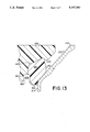
- FIG. 13 is a partial cross-section view of the plug and sealing member in a "sealed” position and under high internal pressure and exposed to both high temperature and an aromatic fuel.
- FIGS. 1 through 4 illustrative views of an improved fuel cap 100 in accordance with the principles of the invention are shown.
- fuel cap 100 is illustrated within an adapter element 110 which defines a tank opening, for example, of an aircraft.
- adapter element 110 which defines a tank opening, for example, of an aircraft.
- the fuel cap has been specifically designed to interface with this adapter element, this is for the purpose of illustration only and not for the purpose of limitation.
- Other suitable adapter elements for various enclosures of aromatic or non-aromatic liquids could utilize the inventive fuel cap.
- fuel cap 100 comprises a plug member 120 having an outwardly extending flange 130 at its upper end and, at its side portion, a first concave groove 140 that circumscribes the entire periphery of plug member 120.
- a sealing member 150 such as made of a fluorosilicone elastomer, is received in concave groove 140 and bonded integrally to the groove which eliminates the necessity of a clinch groove disclosed in the prior art.
- integrally bonded it is meant that there is no apparent structural separation between sealing member 150 and concave groove 140; thus acting as a single element.
- sealing member 150 is generally oblong in shape to assist in the sealing at high internal pressures.
- sealing member 150 has a lower portion 160 which in cross-section has a semi-circular lower surface.
- the sealing member further has a downwardly and radially inwardly tapered sidewall 170 opposing concave groove 140 in the plug member. This taper is provided in order to permit sealing member 150 to move more readily inwardly along annular wall 210 of the adapter as the cap is inserted into the adapter. Tapered sidewall 170 permits sealing of the fuel cap with adapter element 110 even when sealing member 150 is swollen.
- plug member 120 has cutout surfaces 180 and 190, defining a radially inwardly disposed second peripheral groove 200 of reduced cross section for accommodating some of the deformation of sealing member 150 due to fuel induced or temperature induced swelling. That is, groove 200 circumscribes sealing member 150 such that radially inward deformation of the sealing member may expand into the volume formed by cutout surfaces 180 and 190.
- groove 200 is of sufficient cross-sectional area to accommodate the maximum fuel induced swelling of sealing member 150.
- groove 200 affords a passage for the internal pressure to push lower portion 160 of the sealing member against adapter element 110, which is discussed below; thereby aiding in the sealing.
- Adapter element 110 is typically constructed with a beveled annular wall 210 extending into the tank to define an opening for receiving a plug member 120 and a locking flange 220 at the bottom of annular wall 210.
- locking flange 220 is provided with openings or slots for permitting male protrusions of locking mechanism 230 to pass therethrough when fuel cap 100 is inserted into adapter element 110 as described in the previously mentioned patents.
- the parts of the fuel cap are connected together by a shaft 240 extending through a central bore 250 of plug member 120.
- a base 260 of locking mechanism 230 is engaged to the lower end of shaft 240.
- An operating handle 270 is pivotally connected by a pin 245 to the upper end of shaft 240 so that the fuel cap may be installed and removed without the use of tools.
- lanyard 280 is preferably connected to the adapter element by a suitable lanyard 280.
- One end of the lanyard is connected through a "T" arrangement to the adapter while the other end is connected to base 260 by a pin 265.
- This lanyard may be constructed of polyurethane or other plastic or non-conductive materials.
- Locking mechanism 230 may be rotated about the axis of plug member 120 and into position under locking flange 220 by turning handle 270 approximately 60°. The rotational movement of locking mechanism 230 allows it to be positioned underneath the undersurface of locking flange 220.
- Handle 270 which is normally in a vertical position when locking mechanism 230 is rotated is then pivoted about pin 245 into a horizontal recess of plug member 120. Urging handle 270 into the horizontal recess lifts shaft 240 upward forcing plug member 120 toward base 260 in a cam like manner which, in turn, forces sealing member 150 against annular wall 210 of adapter element 110.
- locking mechanism 230 is forced to engage the undersurface of locking flange 220, locking fuel cap 100 in a "sealed" position within the tank opening.
- handle 270 is first pivoted to its vertical position. In this position, the cap is locked against vertical upward movement and removal from the adapter, but is not in full pressure engagement against the adapter.
- This position which is shown in FIG. 8 is a "release" position where internal pressure of the tank can be released. In the "release” position, locking mechanism 230 is disengaged from the undersurface of locking flange 220.
- the cap 100 may then be removed from the tank opening by rotating handle 270 approximately 60° about its axis in a counter-clockwise manner to align the slots in flange 220 with male protrusions of locking mechanism 230.
- a compression spring 290 advantageously encircles shaft 240 so as to normally urge plug member 120 away from base 260.
- Sealing member 150 is bonded to concave groove 140 by a molded insert process. This process bonds sealing member 150 to concave groove 140 of plug member 120 as the sealing member is taking shape in the mold. More specifically, a mold is formed in which a molding cavity is defined by concave groove 140 of the fuel cap and a metallic die having an interior surface that is the same as the desired outer surface of sealing member 150. The metallic die and plug member 120 are raised to the molten temperature of the sealing member. The material of sealing member 150 is then injected in liquid form into the cavity at pressures of over 5,000 psi. A special adhesive allows the seal to stick to concave groove 140 at the high temperature of the liquid state of sealing member 150. Sealing member 150 and plug member 120 are then placed in the oven at a temperature of approximately 400° F. for four hours to allow sealing member 150 to cure.
- the above molded insert process bonds sealing member 150 to concave groove 140 such that the bond is as strong as the material of the sealing member. Under extreme relief pressures (>40 psi), this strong bond prevents the sealing member from detaching from concave groove 140 or rupturing into several pieces.
- the contact surface between concave groove 140 and sealing member 150 is of sufficient area to provide the necessary bonding strength for the desired application.
- sealing element 150 allows swelling to be accommodated by groove 200 in addition to aiding the sealing under high pressure.
- FIG. 5 there is shown a partial cross-sectional enlarged view of plug member 120 and sealing member 150 isolated from adapter element 110.
- the lower portion 160 of sealing member 150 extends vertically below cutout surface 190.
- lower portion 160 includes a semicircular downwardly extending surface facing and capable of being deformed against annular wall 210 when the fuel cap is in its "sealed" position, as shown in FIG. 6.
- Sidewall 170 is tapered at an angle ⁇ in the downward radially inward direction.
- sealing member 150 For low internal pressures, the compression between sealing member 150 and annular wall 210 that results from plug member 120 being urged toward adapter element 110 during locking is sufficient to effectuate sealing. For low pressures (approximately less than 10 psi), sealing member 150 distorts, with a slight bulge directed inwardly from annular wall 210 and a substantially flat surface against annular wall 210.
- FIG. 7 illustrates fuel cap 100 in a "sealed position" and under a high internal pressure (approximately 100 psi).
- the resulting applied force due to the pressure is indicated by arrows and acts against the inner surface of lower portion 160.
- groove 200 affords a passage for the applied pressure to push sealing member 150 against annular wall 210, thereby creating a tighter circumferential seal therebetween with respect to a low pressure condition.
- sealing member 150 prevent any leakage.
- the utilization of an integral base and sealing member provides sufficient strength and resilience to retain the sealing member in concave groove 140 such that the force exerted by the internal pressure does not force the sealing member out of the groove.
- Lifting handle 270 into the "release” position results in an upward movement of plug member 120 resulting from the effects of the confined tank pressure. This upward movement disengages sealing member 150 from annular wall 210. As illustrated in FIG. 8, this "release" position provides a clearance 300 defining an air passage between sealing member 150 and annular wall 210 to permit adequate pressure relief. For comparison purposes, the relation between plug member 120 and annular wall 210 in the "sealed" position is indicated by dash lines.
- sealing member 150 is exposed to aromatic fuels or extreme high and low temperatures, it is important that any induced swelling or contraction be appropriately accommodated by the clearance between annular wall 210 and sealing member 150 so as not to interfere with the proper performance of the seal. With the present invention, this is accomplished by constructing fuel cap 100 such that in its "release" position the clearance 300 between annular wall 210 and sealing member 150 is greater than the swelling of sealing member 150.
- sealing member 150 and inwardly disposed groove 200 accommodate the effects of swelling and contraction, it is advantageous to examine the physical deformation of sealing member 150 under swelling or contraction conditions for varying environmental conditions, e.g., low and high temperatures, and low and high pressures.
- any swelling indicated by dash lines
- concave groove 140 prevents expansion radially inward and has the effect of limiting expansion radially outwardly.
- sealing member 150 expands vertically downwardly from a length L to a length L+ ⁇ 1, with the nominal radius of curvature of lower portion 160 slightly increasing.
- sealing member 150 will deform to a different shape and have a different surface contact area on annular wall 210. Swelling normally enlarges this surface contact area to the annular wall so as to enhance the seal therebetween.
- sealing member 150 being exposed to aromatic fuels is that lower portion 160 extends slightly more over the inward edge of annular wall 210 and that sidewall 170 bulges slightly onto annular wall 210, as illustrated in FIG. 11.
- sealing member 150 is constructed with sidewall 170 having a downward radially inward taper, preferably 8° from the vertical plane, which substantially obviates the problem.
- FIG. 6 shows in dashed lines the effects of cold temperature.
- Plug member 120 is made from a non-conductive material to ensure that the fuel cap is safe from lightning and immune from electrical sparking. Such a requirement is necessary due to the highly combustible characteristic of aircraft fuels.
- plug member 120 is made from a thermoplastic, such as either a polyether-imide resin containing a 20% glass reinforced resin or a polyamide-imide resin containing a 30% glass reinforced resin.
- the glass reinforced resin provides rigidity and stability that enable the fuel cap to withstand vibration encountered during normal use.
- a suitable deformable material for sealing member 150 is fluorosilicone. Such a material when exposed to aromatic fuels has minimal volumetric swelling, typical less than 25%, as well as good pliant characteristics at temperatures near -65° F. Moreover, fluorosilicone readily bonds to either polyether-imide or polyamide-imide.
- plug member 120 is constructed of a polyether-imide resin containing 20% glass resin while sealing member 150 is constructed of fluorosilicone.
- Sidewall 170 is constructed to have downward radially inward taper of 8°. Pressure relief at three levels (5, 25 and 40 psi) are satisfactory. Particularly, for each pressure level, the desired pressure is trapped in the tank with the fuel cap locked. Lifting handle 270 releases the trapped pressure without damaging sealing member 150. Moreover, when the fuel cap is in the "sealed" position, sealing member 150 effectively seals to annular wall 210.
Landscapes
- Engineering & Computer Science (AREA)
- Life Sciences & Earth Sciences (AREA)
- Sustainable Development (AREA)
- Sustainable Energy (AREA)
- Chemical & Material Sciences (AREA)
- Combustion & Propulsion (AREA)
- Transportation (AREA)
- Mechanical Engineering (AREA)
- Cooling, Air Intake And Gas Exhaust, And Fuel Tank Arrangements In Propulsion Units (AREA)
- Closures For Containers (AREA)
Abstract
Description
Claims (18)
Priority Applications (1)
| Application Number | Priority Date | Filing Date | Title |
|---|---|---|---|
| US07/867,949 US5167340A (en) | 1992-04-13 | 1992-04-13 | Fuel cap with a molded seal |
Applications Claiming Priority (1)
| Application Number | Priority Date | Filing Date | Title |
|---|---|---|---|
| US07/867,949 US5167340A (en) | 1992-04-13 | 1992-04-13 | Fuel cap with a molded seal |
Publications (1)
| Publication Number | Publication Date |
|---|---|
| US5167340A true US5167340A (en) | 1992-12-01 |
Family
ID=25350778
Family Applications (1)
| Application Number | Title | Priority Date | Filing Date |
|---|---|---|---|
| US07/867,949 Expired - Lifetime US5167340A (en) | 1992-04-13 | 1992-04-13 | Fuel cap with a molded seal |
Country Status (1)
| Country | Link |
|---|---|
| US (1) | US5167340A (en) |
Cited By (19)
| Publication number | Priority date | Publication date | Assignee | Title |
|---|---|---|---|---|
| EP0868361A4 (en) * | 1995-12-04 | 1999-06-16 | Stant Mfg Co | Quick-on fuel cap |
| US6161841A (en) * | 1999-03-22 | 2000-12-19 | Shaw; Richard J. | Vehicle O ring fuel cap gasket |
| US20020096522A1 (en) * | 2001-01-19 | 2002-07-25 | Sander Palvoelgyi | Fuel tank with lid |
| US20030173362A1 (en) * | 2002-03-18 | 2003-09-18 | Kazuhisa Ishida | Fuel cap |
| US20050003095A1 (en) * | 2002-05-01 | 2005-01-06 | Jeffery Griffin | Method for making a filler neck closure |
| EP1359043A3 (en) * | 2002-04-30 | 2006-10-04 | Eaton Corporation | Siphonable check valve and method of making same |
| US20070170187A1 (en) * | 2006-01-20 | 2007-07-26 | Bemis Manufacturing Company | Modular ratchet cap |
| US20080000906A1 (en) * | 2006-06-30 | 2008-01-03 | Tony Nicosia | Flush-mount fuel cap with valve |
| US20090276991A1 (en) * | 2005-06-23 | 2009-11-12 | Kazuhiro Sakamoto | Fuel tank |
| DE10042640B4 (en) * | 1999-09-08 | 2010-04-29 | Magna Steyr Fuel Systems Gesmbh | Closure for a filler neck with seal |
| US20100230628A1 (en) * | 2007-11-30 | 2010-09-16 | Borgwarner Inc. | Self-retaining plastic snap plugs |
| US20110114637A1 (en) * | 2008-07-11 | 2011-05-19 | Moenig Stefan | Safety system having a tank closure |
| US20110284542A1 (en) * | 2010-05-19 | 2011-11-24 | Darrell Mackay | Fuel cap cover |
| US9045932B2 (en) | 2012-04-05 | 2015-06-02 | Allied Moulded Products, Inc. | Hole seal |
| US9150311B2 (en) | 2012-01-04 | 2015-10-06 | Israel Aerospace Industries Ltd. | Systems and methods for air vehicles |
| US9493066B2 (en) | 2014-12-25 | 2016-11-15 | Central Illinois Manufacturing Company | Vented valve cap |
| US11465768B2 (en) | 2017-07-10 | 2022-10-11 | Israel Aerospace Industries Ltd. | Refueling device |
| US11919655B2 (en) | 2017-06-18 | 2024-03-05 | Israel Aerospace Industries Ltd. | System and method for refueling air vehicles |
| US20240270454A1 (en) * | 2023-02-14 | 2024-08-15 | Toyota Jidosha Kabushiki Kaisha | Receptacle cap |
Citations (16)
| Publication number | Priority date | Publication date | Assignee | Title |
|---|---|---|---|---|
| US1346877A (en) * | 1920-01-15 | 1920-07-20 | Composition Machinery Corp | Filler-cap for receptacles |
| US2844274A (en) * | 1954-04-28 | 1958-07-22 | Universal Metal Products Inc | Filler cap |
| US2969252A (en) * | 1958-08-25 | 1961-01-24 | Gruver And Associates Inc | Seal |
| US3216608A (en) * | 1963-09-12 | 1965-11-09 | Dole Valve Co | Pressure cap for sealed cooling system |
| US3280372A (en) * | 1964-11-10 | 1966-10-18 | Chester Corp | Grounding means for filler cap |
| US3343707A (en) * | 1965-10-22 | 1967-09-26 | Chester Corp | Closure cap for fuel tanks |
| US3391817A (en) * | 1967-07-19 | 1968-07-09 | Shaw Aero Devices Inc | Filler cap |
| US3912117A (en) * | 1974-10-29 | 1975-10-14 | Gen Motors Corp | Fuel tank extendable filler neck assembly |
| US3921849A (en) * | 1973-12-03 | 1975-11-25 | Itw Ltd | Sealing caps |
| US4189059A (en) * | 1978-07-10 | 1980-02-19 | Shaw Aero Devices, Inc. | Sealing mechanism for aircraft fuel tank cap |
| US4416391A (en) * | 1981-08-13 | 1983-11-22 | Compagnie Des Produits Industriels De L'ouest | Seals-caps for fuel tanks |
| US4494673A (en) * | 1983-05-04 | 1985-01-22 | O M Industrial Co., Ltd. | Safety plastic filler neck cap |
| US4497419A (en) * | 1984-02-02 | 1985-02-05 | Stant Inc. | One-piece cap |
| US4768677A (en) * | 1986-10-21 | 1988-09-06 | Nihon Radiator Co., Ltd | Fuel tank cap |
| US4790449A (en) * | 1988-01-16 | 1988-12-13 | Om Industrial Co., Ltd. | Safety plastic filler neck cap |
| US4892216A (en) * | 1989-01-13 | 1990-01-09 | Shaw Aero Development Inc. | Fuel filler cap with overpressure relief |
-
1992
- 1992-04-13 US US07/867,949 patent/US5167340A/en not_active Expired - Lifetime
Patent Citations (16)
| Publication number | Priority date | Publication date | Assignee | Title |
|---|---|---|---|---|
| US1346877A (en) * | 1920-01-15 | 1920-07-20 | Composition Machinery Corp | Filler-cap for receptacles |
| US2844274A (en) * | 1954-04-28 | 1958-07-22 | Universal Metal Products Inc | Filler cap |
| US2969252A (en) * | 1958-08-25 | 1961-01-24 | Gruver And Associates Inc | Seal |
| US3216608A (en) * | 1963-09-12 | 1965-11-09 | Dole Valve Co | Pressure cap for sealed cooling system |
| US3280372A (en) * | 1964-11-10 | 1966-10-18 | Chester Corp | Grounding means for filler cap |
| US3343707A (en) * | 1965-10-22 | 1967-09-26 | Chester Corp | Closure cap for fuel tanks |
| US3391817A (en) * | 1967-07-19 | 1968-07-09 | Shaw Aero Devices Inc | Filler cap |
| US3921849A (en) * | 1973-12-03 | 1975-11-25 | Itw Ltd | Sealing caps |
| US3912117A (en) * | 1974-10-29 | 1975-10-14 | Gen Motors Corp | Fuel tank extendable filler neck assembly |
| US4189059A (en) * | 1978-07-10 | 1980-02-19 | Shaw Aero Devices, Inc. | Sealing mechanism for aircraft fuel tank cap |
| US4416391A (en) * | 1981-08-13 | 1983-11-22 | Compagnie Des Produits Industriels De L'ouest | Seals-caps for fuel tanks |
| US4494673A (en) * | 1983-05-04 | 1985-01-22 | O M Industrial Co., Ltd. | Safety plastic filler neck cap |
| US4497419A (en) * | 1984-02-02 | 1985-02-05 | Stant Inc. | One-piece cap |
| US4768677A (en) * | 1986-10-21 | 1988-09-06 | Nihon Radiator Co., Ltd | Fuel tank cap |
| US4790449A (en) * | 1988-01-16 | 1988-12-13 | Om Industrial Co., Ltd. | Safety plastic filler neck cap |
| US4892216A (en) * | 1989-01-13 | 1990-01-09 | Shaw Aero Development Inc. | Fuel filler cap with overpressure relief |
Cited By (41)
| Publication number | Priority date | Publication date | Assignee | Title |
|---|---|---|---|---|
| US6095363A (en) * | 1994-05-06 | 2000-08-01 | Stant Manufacturing Inc. | Quick-on fuel cap |
| EP0868361A4 (en) * | 1995-12-04 | 1999-06-16 | Stant Mfg Co | Quick-on fuel cap |
| US6161841A (en) * | 1999-03-22 | 2000-12-19 | Shaw; Richard J. | Vehicle O ring fuel cap gasket |
| DE10042640B4 (en) * | 1999-09-08 | 2010-04-29 | Magna Steyr Fuel Systems Gesmbh | Closure for a filler neck with seal |
| US7063226B2 (en) * | 2001-01-19 | 2006-06-20 | Tesma Motoren Und Getriebetechnik | Fuel tank with lid |
| US20020096522A1 (en) * | 2001-01-19 | 2002-07-25 | Sander Palvoelgyi | Fuel tank with lid |
| US6913163B2 (en) * | 2002-03-18 | 2005-07-05 | Toyoda Gosei Co., Ltd. | Fuel cap |
| US20030173362A1 (en) * | 2002-03-18 | 2003-09-18 | Kazuhisa Ishida | Fuel cap |
| EP1359043A3 (en) * | 2002-04-30 | 2006-10-04 | Eaton Corporation | Siphonable check valve and method of making same |
| US7163117B2 (en) | 2002-05-01 | 2007-01-16 | Stant Manufacturing Inc. | Static charge dissipater for filler neck closure |
| US20050003095A1 (en) * | 2002-05-01 | 2005-01-06 | Jeffery Griffin | Method for making a filler neck closure |
| US20090276991A1 (en) * | 2005-06-23 | 2009-11-12 | Kazuhiro Sakamoto | Fuel tank |
| US9162564B2 (en) * | 2005-06-23 | 2015-10-20 | Honda Motor Co., Ltd. | Fuel tank |
| US20070175514A1 (en) * | 2006-01-20 | 2007-08-02 | Bemis Manufacturing Company | Vent including a separator membrane |
| US7624889B2 (en) | 2006-01-20 | 2009-12-01 | Bemis Manufacturing Company | Locking cap |
| US20070169524A1 (en) * | 2006-01-20 | 2007-07-26 | Bemis Manufacturing Company | Locking cap |
| US20070170187A1 (en) * | 2006-01-20 | 2007-07-26 | Bemis Manufacturing Company | Modular ratchet cap |
| US8074334B2 (en) | 2006-01-20 | 2011-12-13 | Bemis Manufacturing Company | Modular ratchet cap |
| JP2008013170A (en) * | 2006-06-30 | 2008-01-24 | Harley-Davidson Motor Co Group Inc | Fuel cap with valve mounted on the same surface |
| US20080000906A1 (en) * | 2006-06-30 | 2008-01-03 | Tony Nicosia | Flush-mount fuel cap with valve |
| US8807375B2 (en) | 2006-06-30 | 2014-08-19 | Harley-Davidson Motor Company Group, LLC | Flush-mount fuel cap with valve |
| US20100230628A1 (en) * | 2007-11-30 | 2010-09-16 | Borgwarner Inc. | Self-retaining plastic snap plugs |
| US8632049B2 (en) * | 2007-11-30 | 2014-01-21 | Borgwarner Inc. | Self-retaining plastic snap plugs |
| US20110114637A1 (en) * | 2008-07-11 | 2011-05-19 | Moenig Stefan | Safety system having a tank closure |
| US20110284542A1 (en) * | 2010-05-19 | 2011-11-24 | Darrell Mackay | Fuel cap cover |
| US10479523B2 (en) | 2012-01-04 | 2019-11-19 | Israel Aerospace Industries Ltd. | Systems and methods for air vehicles |
| US10543929B2 (en) | 2012-01-04 | 2020-01-28 | Israel Aerospace Industries Ltd. | Systems and method for air vehicles |
| US9457912B2 (en) | 2012-01-04 | 2016-10-04 | Israel Aerospace Industries Ltd. | Systems and methods for air vehicles |
| US11834192B2 (en) | 2012-01-04 | 2023-12-05 | Israel Aerospace Industries Ltd. | Devices, systems and methods for refueling air vehicles |
| US9573696B2 (en) | 2012-01-04 | 2017-02-21 | Israel Aerospace Industries Ltd. | Systems and methods for air vehicles |
| US11180262B2 (en) | 2012-01-04 | 2021-11-23 | Israel Aerospace Industries Ltd. | Devices, systems and methods for refueling air vehicles |
| US11167860B2 (en) | 2012-01-04 | 2021-11-09 | Israel Aerospace Industries Ltd. | Devices, systems and methods for refueling air vehicles |
| US10421556B2 (en) | 2012-01-04 | 2019-09-24 | Israel Aerospace Industries Ltd. | Devices, systems and methods for refueling air vehicles |
| US9150311B2 (en) | 2012-01-04 | 2015-10-06 | Israel Aerospace Industries Ltd. | Systems and methods for air vehicles |
| US10427801B2 (en) | 2012-01-04 | 2019-10-01 | Israel Aerospace Industries Ltd. | Devices, systems and methods for refueling air vehicles |
| US9045932B2 (en) | 2012-04-05 | 2015-06-02 | Allied Moulded Products, Inc. | Hole seal |
| US9707840B2 (en) | 2014-12-25 | 2017-07-18 | Central Illinois Manufacturing Company | Vented valve cap |
| US9493066B2 (en) | 2014-12-25 | 2016-11-15 | Central Illinois Manufacturing Company | Vented valve cap |
| US11919655B2 (en) | 2017-06-18 | 2024-03-05 | Israel Aerospace Industries Ltd. | System and method for refueling air vehicles |
| US11465768B2 (en) | 2017-07-10 | 2022-10-11 | Israel Aerospace Industries Ltd. | Refueling device |
| US20240270454A1 (en) * | 2023-02-14 | 2024-08-15 | Toyota Jidosha Kabushiki Kaisha | Receptacle cap |
Similar Documents
| Publication | Publication Date | Title |
|---|---|---|
| US5167340A (en) | Fuel cap with a molded seal | |
| US5071020A (en) | Radiator neck with radiator cover cap | |
| US6202872B1 (en) | Composite closure with enhanced sealing | |
| CA1174478A (en) | Pressure cooker interlock | |
| JP2735696B2 (en) | Seal structure of fluid coupling | |
| US6223923B1 (en) | Lockable safety release gas cap | |
| JPH01500716A (en) | junction box | |
| EP0495916B1 (en) | Fuel sender locking ring | |
| US3092280A (en) | Crown caps | |
| JPWO2003044397A1 (en) | Pressure release valve | |
| US3695482A (en) | Pressure vessel seal | |
| US3186580A (en) | Closure device | |
| US4189059A (en) | Sealing mechanism for aircraft fuel tank cap | |
| EP0075397B1 (en) | Fluid container with venting means | |
| US2079164A (en) | Relief valve | |
| JPH0640262A (en) | Lid for filler pipe of tank | |
| US4993602A (en) | Pressure relief device for a pressurized container | |
| JPH0436949B2 (en) | ||
| EP2287503A1 (en) | Gasket for a pressure relief device | |
| US6089415A (en) | Valve for a pressure container | |
| CA1279034C (en) | Sealing cap for a safety container | |
| US4234199A (en) | Sealing arrangements | |
| US3734125A (en) | Pressurized container dispensing valve having excessive pressure safety feature | |
| US5056678A (en) | Access port sealing device | |
| US5102172A (en) | Fuel sender locking ring |
Legal Events
| Date | Code | Title | Description |
|---|---|---|---|
| AS | Assignment |
Owner name: SHAW AERO DEVICES, INC., NEW YORK Free format text: ASSIGNMENT OF ASSIGNORS INTEREST.;ASSIGNOR:SHAW, JAMES R.;REEL/FRAME:006095/0323 Effective date: 19920304 |
|
| STCF | Information on status: patent grant |
Free format text: PATENTED CASE |
|
| FPAY | Fee payment |
Year of fee payment: 4 |
|
| FPAY | Fee payment |
Year of fee payment: 8 |
|
| AS | Assignment |
Owner name: ORIX FINANCIAL SERVICES, INC., ILLINOIS Free format text: SECURITY AGREEMENT;ASSIGNOR:SHAW AERO DEVICES, INC.;REEL/FRAME:015147/0782 Effective date: 20040227 |
|
| FPAY | Fee payment |
Year of fee payment: 12 |
|
| AS | Assignment |
Owner name: SHAW AERO DEVICES, INC., FLORIDA Free format text: RELEASE BY SECURED PARTY;ASSIGNOR:ORIX FINANCIAL SERVICES, INC.;REEL/FRAME:019930/0001 Effective date: 20071008 |
|
| AS | Assignment |
Owner name: PARKER-HANNIFIN CORPORATION, OHIO Free format text: MERGER;ASSIGNOR:SHAW AERO DEVICES, INC.;REEL/FRAME:020690/0114 Effective date: 20071220 |
|
| AS | Assignment |
Owner name: PARKER INTANGIBLES LLC, OHIO Free format text: ASSIGNMENT OF ASSIGNORS INTEREST;ASSIGNOR:PARKER-HANNIFIN CORPORATION;REEL/FRAME:023180/0380 Effective date: 20090825 Owner name: PARKER INTANGIBLES LLC,OHIO Free format text: ASSIGNMENT OF ASSIGNORS INTEREST;ASSIGNOR:PARKER-HANNIFIN CORPORATION;REEL/FRAME:023180/0380 Effective date: 20090825 |