EP1983181A1 - Steuerung des kraftstoff-luft-verhältnisses für einen verbrennungsmotor - Google Patents
Steuerung des kraftstoff-luft-verhältnisses für einen verbrennungsmotor Download PDFInfo
- Publication number
- EP1983181A1 EP1983181A1 EP07714129A EP07714129A EP1983181A1 EP 1983181 A1 EP1983181 A1 EP 1983181A1 EP 07714129 A EP07714129 A EP 07714129A EP 07714129 A EP07714129 A EP 07714129A EP 1983181 A1 EP1983181 A1 EP 1983181A1
- Authority
- EP
- European Patent Office
- Prior art keywords
- fuel ratio
- air
- way catalyst
- temperature
- catalyst apparatus
- Prior art date
- Legal status (The legal status is an assumption and is not a legal conclusion. Google has not performed a legal analysis and makes no representation as to the accuracy of the status listed.)
- Withdrawn
Links
Images
Classifications
-
- F—MECHANICAL ENGINEERING; LIGHTING; HEATING; WEAPONS; BLASTING
- F01—MACHINES OR ENGINES IN GENERAL; ENGINE PLANTS IN GENERAL; STEAM ENGINES
- F01N—GAS-FLOW SILENCERS OR EXHAUST APPARATUS FOR MACHINES OR ENGINES IN GENERAL; GAS-FLOW SILENCERS OR EXHAUST APPARATUS FOR INTERNAL-COMBUSTION ENGINES
- F01N3/00—Exhaust or silencing apparatus having means for purifying, rendering innocuous, or otherwise treating exhaust
- F01N3/08—Exhaust or silencing apparatus having means for purifying, rendering innocuous, or otherwise treating exhaust for rendering innocuous
- F01N3/10—Exhaust or silencing apparatus having means for purifying, rendering innocuous, or otherwise treating exhaust for rendering innocuous by thermal or catalytic conversion of noxious components of exhaust
- F01N3/24—Exhaust or silencing apparatus having means for purifying, rendering innocuous, or otherwise treating exhaust for rendering innocuous by thermal or catalytic conversion of noxious components of exhaust characterised by constructional aspects of converting apparatus
-
- F—MECHANICAL ENGINEERING; LIGHTING; HEATING; WEAPONS; BLASTING
- F01—MACHINES OR ENGINES IN GENERAL; ENGINE PLANTS IN GENERAL; STEAM ENGINES
- F01N—GAS-FLOW SILENCERS OR EXHAUST APPARATUS FOR MACHINES OR ENGINES IN GENERAL; GAS-FLOW SILENCERS OR EXHAUST APPARATUS FOR INTERNAL-COMBUSTION ENGINES
- F01N3/00—Exhaust or silencing apparatus having means for purifying, rendering innocuous, or otherwise treating exhaust
- F01N3/08—Exhaust or silencing apparatus having means for purifying, rendering innocuous, or otherwise treating exhaust for rendering innocuous
- F01N3/10—Exhaust or silencing apparatus having means for purifying, rendering innocuous, or otherwise treating exhaust for rendering innocuous by thermal or catalytic conversion of noxious components of exhaust
- F01N3/101—Three-way catalysts
-
- F—MECHANICAL ENGINEERING; LIGHTING; HEATING; WEAPONS; BLASTING
- F01—MACHINES OR ENGINES IN GENERAL; ENGINE PLANTS IN GENERAL; STEAM ENGINES
- F01N—GAS-FLOW SILENCERS OR EXHAUST APPARATUS FOR MACHINES OR ENGINES IN GENERAL; GAS-FLOW SILENCERS OR EXHAUST APPARATUS FOR INTERNAL-COMBUSTION ENGINES
- F01N3/00—Exhaust or silencing apparatus having means for purifying, rendering innocuous, or otherwise treating exhaust
- F01N3/08—Exhaust or silencing apparatus having means for purifying, rendering innocuous, or otherwise treating exhaust for rendering innocuous
- F01N3/10—Exhaust or silencing apparatus having means for purifying, rendering innocuous, or otherwise treating exhaust for rendering innocuous by thermal or catalytic conversion of noxious components of exhaust
- F01N3/18—Exhaust or silencing apparatus having means for purifying, rendering innocuous, or otherwise treating exhaust for rendering innocuous by thermal or catalytic conversion of noxious components of exhaust characterised by methods of operation; Control
- F01N3/20—Exhaust or silencing apparatus having means for purifying, rendering innocuous, or otherwise treating exhaust for rendering innocuous by thermal or catalytic conversion of noxious components of exhaust characterised by methods of operation; Control specially adapted for catalytic conversion
- F01N3/2006—Periodically heating or cooling catalytic reactors, e.g. at cold starting or overheating
-
- F—MECHANICAL ENGINEERING; LIGHTING; HEATING; WEAPONS; BLASTING
- F02—COMBUSTION ENGINES; HOT-GAS OR COMBUSTION-PRODUCT ENGINE PLANTS
- F02D—CONTROLLING COMBUSTION ENGINES
- F02D41/00—Electrical control of supply of combustible mixture or its constituents
- F02D41/02—Circuit arrangements for generating control signals
- F02D41/021—Introducing corrections for particular conditions exterior to the engine
- F02D41/0235—Introducing corrections for particular conditions exterior to the engine in relation with the state of the exhaust gas treating apparatus
- F02D41/024—Introducing corrections for particular conditions exterior to the engine in relation with the state of the exhaust gas treating apparatus to increase temperature of the exhaust gas treating apparatus
- F02D41/0255—Introducing corrections for particular conditions exterior to the engine in relation with the state of the exhaust gas treating apparatus to increase temperature of the exhaust gas treating apparatus to accelerate the warming-up of the exhaust gas treating apparatus at engine start
-
- F—MECHANICAL ENGINEERING; LIGHTING; HEATING; WEAPONS; BLASTING
- F01—MACHINES OR ENGINES IN GENERAL; ENGINE PLANTS IN GENERAL; STEAM ENGINES
- F01N—GAS-FLOW SILENCERS OR EXHAUST APPARATUS FOR MACHINES OR ENGINES IN GENERAL; GAS-FLOW SILENCERS OR EXHAUST APPARATUS FOR INTERNAL-COMBUSTION ENGINES
- F01N2340/00—Dimensional characteristics of the exhaust system, e.g. length, diameter or volume of the exhaust apparatus; Spatial arrangements of exhaust apparatuses
-
- F—MECHANICAL ENGINEERING; LIGHTING; HEATING; WEAPONS; BLASTING
- F01—MACHINES OR ENGINES IN GENERAL; ENGINE PLANTS IN GENERAL; STEAM ENGINES
- F01N—GAS-FLOW SILENCERS OR EXHAUST APPARATUS FOR MACHINES OR ENGINES IN GENERAL; GAS-FLOW SILENCERS OR EXHAUST APPARATUS FOR INTERNAL-COMBUSTION ENGINES
- F01N2430/00—Influencing exhaust purification, e.g. starting of catalytic reaction, filter regeneration, or the like, by controlling engine operating characteristics
- F01N2430/06—Influencing exhaust purification, e.g. starting of catalytic reaction, filter regeneration, or the like, by controlling engine operating characteristics by varying fuel-air ratio, e.g. by enriching fuel-air mixture
-
- F—MECHANICAL ENGINEERING; LIGHTING; HEATING; WEAPONS; BLASTING
- F01—MACHINES OR ENGINES IN GENERAL; ENGINE PLANTS IN GENERAL; STEAM ENGINES
- F01N—GAS-FLOW SILENCERS OR EXHAUST APPARATUS FOR MACHINES OR ENGINES IN GENERAL; GAS-FLOW SILENCERS OR EXHAUST APPARATUS FOR INTERNAL-COMBUSTION ENGINES
- F01N2560/00—Exhaust systems with means for detecting or measuring exhaust gas components or characteristics
- F01N2560/06—Exhaust systems with means for detecting or measuring exhaust gas components or characteristics the means being a temperature sensor
-
- F—MECHANICAL ENGINEERING; LIGHTING; HEATING; WEAPONS; BLASTING
- F01—MACHINES OR ENGINES IN GENERAL; ENGINE PLANTS IN GENERAL; STEAM ENGINES
- F01N—GAS-FLOW SILENCERS OR EXHAUST APPARATUS FOR MACHINES OR ENGINES IN GENERAL; GAS-FLOW SILENCERS OR EXHAUST APPARATUS FOR INTERNAL-COMBUSTION ENGINES
- F01N2560/00—Exhaust systems with means for detecting or measuring exhaust gas components or characteristics
- F01N2560/14—Exhaust systems with means for detecting or measuring exhaust gas components or characteristics having more than one sensor of one kind
-
- F—MECHANICAL ENGINEERING; LIGHTING; HEATING; WEAPONS; BLASTING
- F02—COMBUSTION ENGINES; HOT-GAS OR COMBUSTION-PRODUCT ENGINE PLANTS
- F02D—CONTROLLING COMBUSTION ENGINES
- F02D2200/00—Input parameters for engine control
- F02D2200/02—Input parameters for engine control the parameters being related to the engine
- F02D2200/08—Exhaust gas treatment apparatus parameters
- F02D2200/0802—Temperature of the exhaust gas treatment apparatus
-
- F—MECHANICAL ENGINEERING; LIGHTING; HEATING; WEAPONS; BLASTING
- F02—COMBUSTION ENGINES; HOT-GAS OR COMBUSTION-PRODUCT ENGINE PLANTS
- F02D—CONTROLLING COMBUSTION ENGINES
- F02D41/00—Electrical control of supply of combustible mixture or its constituents
- F02D41/02—Circuit arrangements for generating control signals
- F02D41/021—Introducing corrections for particular conditions exterior to the engine
- F02D41/0235—Introducing corrections for particular conditions exterior to the engine in relation with the state of the exhaust gas treating apparatus
- F02D41/024—Introducing corrections for particular conditions exterior to the engine in relation with the state of the exhaust gas treating apparatus to increase temperature of the exhaust gas treating apparatus
- F02D41/0245—Introducing corrections for particular conditions exterior to the engine in relation with the state of the exhaust gas treating apparatus to increase temperature of the exhaust gas treating apparatus by increasing temperature of the exhaust gas leaving the engine
-
- F—MECHANICAL ENGINEERING; LIGHTING; HEATING; WEAPONS; BLASTING
- F02—COMBUSTION ENGINES; HOT-GAS OR COMBUSTION-PRODUCT ENGINE PLANTS
- F02D—CONTROLLING COMBUSTION ENGINES
- F02D41/00—Electrical control of supply of combustible mixture or its constituents
- F02D41/02—Circuit arrangements for generating control signals
- F02D41/021—Introducing corrections for particular conditions exterior to the engine
- F02D41/0235—Introducing corrections for particular conditions exterior to the engine in relation with the state of the exhaust gas treating apparatus
- F02D41/024—Introducing corrections for particular conditions exterior to the engine in relation with the state of the exhaust gas treating apparatus to increase temperature of the exhaust gas treating apparatus
- F02D41/025—Introducing corrections for particular conditions exterior to the engine in relation with the state of the exhaust gas treating apparatus to increase temperature of the exhaust gas treating apparatus by changing the composition of the exhaust gas, e.g. for exothermic reaction on exhaust gas treating apparatus
-
- Y—GENERAL TAGGING OF NEW TECHNOLOGICAL DEVELOPMENTS; GENERAL TAGGING OF CROSS-SECTIONAL TECHNOLOGIES SPANNING OVER SEVERAL SECTIONS OF THE IPC; TECHNICAL SUBJECTS COVERED BY FORMER USPC CROSS-REFERENCE ART COLLECTIONS [XRACs] AND DIGESTS
- Y02—TECHNOLOGIES OR APPLICATIONS FOR MITIGATION OR ADAPTATION AGAINST CLIMATE CHANGE
- Y02T—CLIMATE CHANGE MITIGATION TECHNOLOGIES RELATED TO TRANSPORTATION
- Y02T10/00—Road transport of goods or passengers
- Y02T10/10—Internal combustion engine [ICE] based vehicles
- Y02T10/12—Improving ICE efficiencies
Definitions
- the present invention relates to an air-fuel ratio control device of an internal combustion engine.
- the exhaust gas of an internal combustion engine contains NOx, CO, HC, etc.
- the engine exhaust system is provided with a three-way catalyst apparatus.
- a three-way catalyst apparatus cannot purify the gas of these substances well before it is raised to the catalyst activation temperature, so at the time of engine startup where the catalyst temperature is low, the three-way catalyst apparatus has to be quickly raised to the catalyst activation temperature.
- the combustion air-fuel ratio be made the stoichiometric air-fuel ratio, but when the fact that three-way catalyst apparatus is raised to the catalyst activation temperature is judged by the engine cooling water temperature reaching a set temperature, the set temperature be set lower the lower the engine cooling water temperature at the time of start of engine startup and the combustion air-fuel ratio be made lean regardless of the three-way catalyst apparatus as a whole being raised to the catalyst activation temperature and thereby the three-way catalyst apparatus be prevented from being excessively raised in temperature (for example, see Japanese Patent Publication (A) No. 9-151759 , Japanese Patent Publication (A) No. 9-222010 , Japanese Patent Publication (A) No. 2004-346777 , and Japanese Patent Publication (A) No. 2004-324493 ).
- an object of the present invention is to provide an air-fuel ratio control device of an internal combustion engine able to reduce the amount of NOx released into the atmosphere when quickly raising the three-way catalyst apparatus to the catalyst activation temperature right after engine startup.
- An air-fuel ratio control device of an internal combustion engine as set forth in claim 1 according to the present invention 1 is characterized by making a combustion air-fuel ratio leaner than a stoichiometric air-fuel ratio at the time of engine startup and when it is judged that just an exhaust upstream part of a three-way catalyst apparatus arranged in an engine exhaust system has been raised to a catalyst activation temperature, making the combustion air-fuel ratio richer than the stoichiometric air-fuel ratio and raising a temperature of an exhaust downstream part of the three-way catalyst apparatus.
- an air-fuel ratio control device of an internal combustion engine as set forth in claim 2 provides an air-fuel ratio control device of an internal combustion engine as set forth in claim 1 characterized in that a volume of the exhaust upstream part of the three-way catalyst apparatus, which makes the combustion air-fuel ratio lean to raise it to the catalyst activation temperature, is changed to become larger the greater the amount of exhaust gas at the time of engine startup.
- an air-fuel ratio control device of an internal combustion engine as set forth in claim 3 provides an air-fuel ratio control device of an internal combustion engine as set forth in claim 1 or 2 characterized in that it is judged that just the exhaust upstream part has been raised to the catalyst activation temperature based on a measurement temperature of a center of the three-way catalyst apparatus in the longitudinal direction.
- an air-fuel ratio control device of an internal combustion engine as set forth in claim 4 provides an air-fuel ratio control device of an internal combustion engine as set forth in any one of claims 1 to 3 characterized in that when it is estimated that the O 2 storage amount of the three-way catalyst apparatus 1 is reduced to a set amount due to the combustion air-fuel ratio being made richer than the stoichiometric air-fuel ratio, the combustion air-fuel ratio is made the stoichiometric air-fuel ratio.
- an air-fuel ratio control device of an internal combustion engine as set forth in claim 5 provides an air-fuel ratio control device of an internal combustion engine as set forth in any one of claims 1 to 3 characterized in that when it is estimated that the O 2 storage amount of the three-way catalyst apparatus 1 is reduced to a set amount due to the combustion air-fuel ratio being made richer than the stoichiometric air-fuel ratio, the combustion air-fuel ratio is made to alternately fluctuate to the rich side and lean side from the stoichiometric air-fuel ratio.
- an air-fuel ratio control device of an internal combustion engine as set forth in claim 6 provides an air-fuel ratio control device of an internal combustion engine as set forth in claim 5 characterized in that an amplitude of the fluctuation of the combustion air-fuel ratio is made smaller the higher the temperature of the exhaust downstream part of the three-way catalyst apparatus.
- an air-fuel ratio control device of an internal combustion engine as set forth in claim 7 provides an air-fuel ratio control device of an internal combustion engine as set forth in claim 5 characterized in that a period of fluctuation of the combustion air-fuel ratio is made larger the higher the temperature of the exhaust downstream part of the three-way catalyst apparatus.
- an air-fuel ratio control device of an internal combustion engine as set forth in claim 1 according to the present invention, at the time of engine startup, first the combustion air-fuel ratio is made leaner than the stoichiometric air-fuel ratio, the sufficient oxygen in the exhaust gas is used to burn the HC and CO in the exhaust gas in the three-way catalyst apparatus, and just the exhaust upstream part of the three-way catalyst apparatus arranged in the engine exhaust system is raised in temperature well. At this time, the cylinder temperature is low, so the combustion temperature is also low and not that much NOx is produced.
- the combustion air-fuel ratio is made richer than the stoichiometric air-fuel ratio, so the cylinder temperature becomes relatively high. Even if the combustion temperature becomes high, not that much NOx is produced in the cylinders. Compared with when making the combustion air-fuel ratio lean, the amount of NOx released into the atmosphere can be reduced.
- the combustion air-fuel ratio being made rich, the HC and CO in the exhaust gas increase, but due to the release of the oxygen stored in the three-way catalyst apparatus by the O 2 storage capacity while the combustion air-fuel ratio was made lean, these HC and CO are burned in the three-way catalyst apparatus and not released into the atmosphere. Further, this heat of combustion can be used to raise the temperature of the exhaust downstream part of the three-way catalyst apparatus better.
- an air-fuel ratio control device of an internal combustion engine as set forth in claim 2 there is provided an air-fuel ratio control device of an internal combustion engine as set forth in claim 1 wherein the volume of the exhaust upstream part of the three-way catalyst apparatus, which makes the combustion air-fuel ratio lean to raise the catalyst activation temperature, is changed to become greater the greater the amount of exhaust gas at the time of engine startup.
- the volume of the three-way catalyst apparatus required for purifying the exhaust gas at the time of engine startup is raised quickly to the catalyst activation temperature due to it being quickly raised in temperature due to the leanness of the combustion air-fuel ratio.
- an air-fuel ratio control device of an internal combustion engine as set forth in claim 3 wherein at least the temperature at the center of the three-way catalyst apparatus in the longitudinal direction is measured by a temperature sensor etc. It is judged based on this measurement temperature that just the exhaust upstream part of the three-way catalyst apparatus has been raised to the catalyst activation temperature.
- the temperature of the three-way catalyst apparatus is highest at the exhaust upstream end and lowest at the exhaust downstream end, so if at least the temperature of the center in the longitudinal direction is measured, it is possible to easily judge if just the exhaust upstream part has been raised to the catalyst activation temperature.
- an air-fuel ratio control device of an internal combustion engine as set forth in claim 4 there is provided an air-fuel ratio control device of an internal combustion engine as set forth in any one of claims 1 to 3 wherein when it is estimated that the O 2 storage amount of the three-way catalyst apparatus 1 has been reduced to a set amount due to the combustion air-fuel ratio being made richer than the stoichiometric air-fuel ratio, the combustion air-fuel ratio is made the stoichiometric air-fuel ratio. Due to operation with the combustion air-fuel ratio made lean, the O 2 storage amount of the three-way catalyst apparatus 1 becomes the maximum storage amount.
- the combustion air-fuel ratio is made rich and it is estimated that the O 2 storage amount of the three-way catalyst apparatus 1 has been reduced to the set amount, preferably to about half of the maximum storage amount, the combustion air-fuel ratio is made the stoichiometric air-fuel ratio and the O 2 storage amount is maintained at the set amount.
- the three-way catalyst apparatus can become the catalyst activation temperature over a broad range from the exhaust upstream part, the HC, CO, and NOx contained in the exhaust gas of the stoichiometric air-fuel ratio can be removed well, and the heat of reaction generated at that time can be used to raise the remaining part of the three-way catalyst apparatus to the catalyst activation temperature.
- an air-fuel ratio control device of an internal combustion engine as set forth in claim 5 there is provided an air-fuel ratio control device of an internal combustion engine as set forth in any one of claims 1 to 3 wherein when it is estimated that the O 2 storage amount of the three-way catalyst apparatus 1 has been reduced to a set amount due to the combustion air-fuel ratio being made richer than the stoichiometric air-fuel ratio, the combustion air-fuel ratio is made to alternately fluctuate to the rich side and lean side from the stoichiometric air-fuel ratio.
- the three-way catalyst apparatus is alternately supplied with relatively large amounts of HC and CO and large amounts of oxygen and NOx. Due to this, relatively large amounts of HC and CO can be burned by the oxygen released from the three-way catalyst apparatus. This heat of combustion can be used to efficiently raise the temperature of the remaining part of the three-way catalyst apparatus not raised to the catalyst activation temperature. The same amount of oxygen as the released oxygen is again stored in the three-way catalyst apparatus, so the O 2 storage amount of the three-way catalyst apparatus 1 can be maintained at a set amount.
- an air-fuel ratio control device of an internal combustion engine as set forth in claim 6 wherein the amplitude of the fluctuation of the combustion air-fuel ratio is made smaller to reduce the amounts of HC and CO and amounts of oxygen and NOx supplied to the three-way catalyst apparatus per unit time the higher the measurement temperature of the exhaust downstream part of the three-way catalyst apparatus and the remaining part of the three-way catalyst apparatus not raised to the catalyst activation temperature due to the heat of combustion of the HC and CO being reduced is raised in temperature. Due to this, more than the necessary heat of combustion being generated and the exhaust upstream part of the three-way catalyst apparatus already raised to the catalyst activation temperature being excessively raised in temperature are also suppressed.
- an air-fuel ratio control device of an internal combustion engine as set forth in claim 7 wherein the period of fluctuation of the combustion air-fuel ratio is made larger the higher the measurement temperature of the exhaust downstream part of the three-way catalyst apparatus to reduce the amounts of HC and CO and the amounts of oxygen and NOx supplied per unit time to the three-way catalyst apparatus and the remaining part of the three-way catalyst apparatus not raised in catalyst activation temperature due to the heats of combustion of the HC and CO being reduced. Due to this, more than the necessary heat of combustion being generated and the exhaust upstream part of the three-way catalyst apparatus already raised to the catalyst activation temperature being excessively raised in temperature are also suppressed.
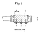
- FIG. 1 is a schematic view showing part of the engine exhaust system.
- 1 indicates a three-way catalyst apparatus
- 2 a first temperature sensor for detecting the temperature near the exhaust upstream end of the three-way catalyst apparatus 1
- 3 a second temperature sensor for detecting the temperature at the center of the three-way catalyst apparatus 1 in the longitudinal direction
- 4 a third temperature sensor for detecting the temperature near the exhaust downstream end of the three-way catalyst apparatus 1.
- the first temperature sensor 2, second temperature sensor 3, and third temperature sensor 4 respectively detect the temperatures near the diametric center at different positions in the longitudinal direction in the present embodiment.
- the three-way catalyst apparatus 1 removes the NOx, CO, and HC in the exhaust gas well when the air-fuel ratio of the exhaust gas is near the stoichiometric air-fuel ratio. However, it is difficult to continuously maintain the air-fuel ratio of the exhaust gas near the stoichiometric air-fuel ratio.
- the three-way catalyst apparatus 1 can remove the NOx, CO, and HC in the exhaust gas near the stoichiometric air-fuel ratio well before reaching the catalyst activation temperature. Due to this, at the time of engine startup where the catalyst temperature is low, it is necessary to raise the three-way catalyst apparatus 1 quickly to the catalyst activation temperature. For this reason, the general practice has been to make the combustion air-fuel ratio leaner than the stoichiometric air-fuel ratio at the time of engine startup to make the exhaust gas contain a large amount of oxygen, to use this oxygen to burn the HC and CO in the exhaust gas well in the three-way catalyst apparatus 1, and to use this heat of combustion to raise the temperature of the three-way catalyst apparatus 1.
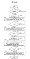
- the combustion air-fuel ratio is controlled in accordance with the flow chart shown in FIG. 2 to raise the three-way catalyst apparatus 1 quickly to the catalyst activation temperature and suppress the amount of NOx released into the atmosphere at that time.
- step 101 it is judged if the engine is starting up by an on signal of a starter switch etc. When this judgment is negative, the routine ends as it is, but when this judgment is positive, the routine proceeds to step 102.
- step 102 the volume of the exhaust upstream part of the three-way catalyst apparatus 1 required for purifying the amount of exhaust gas at the time of engine startup corresponding to the amount of intake air at the time of engine startup, preferably the amount of intake air at the time of a steady state operation right after the cylinders have finished starting firing and the engine speed rises to a set speed (below, "right after completion of engine startup") is determined.
- This volume is for example determined as the length L from the exhaust upstream end in a three-way catalyst apparatus having a uniform diameter.
- the engine is operated under a lean air-fuel ratio (for example, 15 to 16).
- the combustion air-fuel ratio may be made lean from the cranking, but until the completion of engine startup, to secure a reliable starting ability, the combustion air-fuel ratio is preferably made the stoichiometric air-fuel ratio or rich air-fuel ratio.
- the operation under a lean air-fuel ratio is preferably started right after the completion of engine startup.
- step 104 it is judged if the temperature TL near the diametrical center at the position of the length L from the exhaust upstream end of the three-way catalyst apparatus 1 has reached the catalyst activation temperature T.
- the three-way catalyst apparatus 1 has a temperature gradient where the temperature gradually becomes lower from the exhaust upstream end to the exhaust downstream end.
- a temperature Tu near the exhaust upstream end is monitored by the first temperature sensor 2
- a temperature Tc near the center of the longitudinal direction is monitored by the second temperature sensor 3
- a temperature Td near the exhaust downstream end is monitored by the third temperature sensor 4. Based on these three temperatures Tu, Tc, and Td, it is possible to estimate the temperature TL at the position of a length L from the exhaust upstream end.
- the volume of the three-way catalyst apparatus required for purification is adjusted.
- the length L from the exhaust upstream end is adjusted.
- the temperature TL at this length position can be estimated based on the above-mentioned three temperatures Tu, Tc, and Td. Further, if at least the temperature Tc of the center of the three-way catalyst apparatus 1 in the longitudinal direction is monitored, the temperature of the exhaust upstream end may be deemed the temperature of the exhaust gas flowing into the three-way catalyst apparatus 1 and the temperature TL at the position of the length L from the exhaust upstream end may be estimated.
- the engine is operated under a lean air-fuel ratio so as to make the exhaust gas contain a sufficient amount of oxygen, whereby the HC and CO in the exhaust gas are burned well in the three-way catalyst apparatus 1 and this heat of combustion is used to raise the temperature of the three-way catalyst apparatus 1 well.
- the temperature inside the cylinder is still low.
- the combustion temperature is also low, so even if the combustion air-fuel ratio is made lean, not that much NOx is produced. In this way, NOx is released into the atmosphere without being purified from the gas that much in the three-way catalyst apparatus, but the amount of the NOx released is slight.
- step 105 the engine is operated under a rich air-fuel ratio (for example, 12 to 14) and the combustion air-fuel ratio is switched from a lean air-fuel ratio to a rich air-fuel ratio.
- the exhaust upstream part of the three-way catalyst apparatus 1 is raised to the catalyst activation temperature.
- the combustion air-fuel ratio is made the stoichiometric air-fuel ratio, the exhaust gas can be purified well right after the completion of engine startup.
- the exhaust downstream part other than the exhaust upstream part of the three-way catalyst apparatus 1 is still not raised to the catalyst activation temperature. In preparation for an increase in the amount of exhaust gas, it is necessary to quickly raise the exhaust downstream part to the catalyst activation temperature.
- the combustion air-fuel ratio is made rich and relatively large amounts of HC and CO are made to flow into the three-way catalyst apparatus 1.
- These HC and CO are burned well in the three-way catalyst apparatus 1 since oxygen stored by the O 2 storage capacity of the three-way catalyst apparatus 1 at the time of a lean air-fuel ratio operation is released from the three-way catalyst apparatus 1.
- the exhaust downstream part of the three-way catalyst apparatus 1 can therefore be raised in temperature well.
- the temperature inside the cylinder is raised by the operation under the lean air-fuel ratio up until then. If the engine continues to be operated under the lean air-fuel ratio as it is, the combustion temperature would also become higher and the amount of production of NOx would end up becoming relatively large. However, in the present embodiment, at this time, the engine is operated under a rich air-fuel ratio, so even if the temperature inside the cylinder becomes high, not that much NOx will be produced. Even if the NOx is not removed in the three-way catalyst apparatus 1, the amount of NOx released into the atmosphere is slight.
- the O 2 storage amount of the three-way catalyst apparatus 1 is for maintaining the air-fuel ratio of the exhaust gas in the three-way catalyst apparatus 1 near the stoichiometric air-fuel ratio even when the combustion air-fuel ratio fluctuates to rich or lean.
- the O 2 storage amount of the three-way catalyst apparatus 1 is preferably about half of the maximum storage amount so that the combustion air-fuel ratio may fluctuate to rich and lean. If leaving the combustion air-fuel ratio rich, the exhaust downstream part of the three-way catalyst apparatus 1 is raised in temperature well, but the oxygen stored up to the maximum storage amount at the time of operation under a lean air-fuel ratio ends up being completely released.
- step 106 it is judged if the time te elapsed from the start of operation under a rich air-fuel ratio has reached a set time t.
- the three-way catalyst apparatus 1 stores the maximum storage amount of oxygen.
- This maximum storage amount is a value known for each three-way catalyst apparatus 1.
- the amount of HC and amount of CO required for halving the maximum storage amount of oxygen are also known. Due to this, the operating time t under a rich air-fuel ratio required for these amount of HC and amount of CO to flow into the three-way catalyst apparatus 1 can be set based on the value of the rich air-fuel ratio.
- step 106 while the judgment at step 106 is negative, the engine is operated under a rich air-fuel ratio.
- the time te elapsed from the start of operation under a rich air-fuel ratio has reached the set time t, if the O 2 storage amount of the three-way catalyst apparatus 1 becomes half of the maximum storage amount, the operation under a rich air-fuel ratio ends and the routine proceeds to step 107.
- the O 2 storage amount of the three-way catalyst apparatus 1 becomes about half of the maximum storage amount, it is also possible to switch the combustion air-fuel ratio from rich to the stoichiometric air-fuel ratio and, at the exhaust downstream part of the three-way catalyst apparatus, raise the temperature of the remaining part still not raised to the catalyst activation temperature using the heat generated when removing the HC, CO, and NOx. Even in such an operation under a stoichiometric air-fuel ratio, the O 2 storage amount of the three-way catalyst apparatus 1 can be maintained at about half of the maximum storage amount.
- the combustion air-fuel ratio is made to fluctuate to the rich side and lean side from the stoichiometric air-fuel ratio
- the relatively large amounts of HC and CO when the combustion air-fuel ratio fluctuates to the rich side are made to flow into the three-way catalyst apparatus 1, and these HC and CO are burned by the oxygen released from the three-way catalyst apparatus.
- the combustion air-fuel ratio fluctuates to the lean side the amount of oxygen released for burning the HC and CO is stored again in the three-way catalyst apparatus 1. In this way, even if the combustion air-fuel ratio fluctuates, the O 2 storage amount of the three-way catalyst apparatus 1 can be maintained at about half of the maximum O 2 storage amount.
- the amplitude A of the fluctuation of the combustion air-fuel ratio is determined.
- the larger the amplitude A the greater the amount of HC and amount of CO supplied to the three-way catalyst apparatus 1 and the more advantageous for raising the temperature of the remaining part not raised to the catalyst activation temperature of the three-way catalyst apparatus 1.
- the exhaust upstream part etc. of the three-way catalyst apparatus 1 already raised to the catalyst activation temperature is easily raised excessively. Due to this, the higher the temperature Td of the exhaust downstream end of the three-way catalyst apparatus 1 detected by the third temperature sensor 4 or estimated from the temperature Tc of the center part of the longitudinal direction of the three-way catalyst apparatus 1 detected by at least the second temperature sensor 3, the smaller the amplitude A is made. Due to this, the exhaust upstream part etc. of the three-way catalyst apparatus 1 already raised to the catalyst activation temperature is kept from being excessively raised in temperature.
- step 107 if the amplitude A of the fluctuation of the combustion air-fuel ratio is determined, at step 108, the engine is operated under a fluctuating air-fuel ratio of the amplitude A from the stoichiometric air-fuel ratio.
- step 109 in the same way as above, it is judged if the detected or estimated temperature Td of the exhaust downstream end of the three-way catalyst apparatus 1 has reached the catalyst activation temperature T. While this judgment is negative, at step 107, the amplitude A is determined and, at step 108, the engine is operated under a fluctuating air-fuel ratio.
- the amplitude A of the fluctuating air-fuel ratio operation was changed, but it is also possible to make the period of fluctuation of the fluctuating air-fuel ratio operation longer the higher the temperature Td of the exhaust downstream end of the three-way catalyst apparatus 1 and reduce the amount of CO and amount of HC supplied to the three-way catalyst apparatus. Due to this, the exhaust upstream part etc. of the three-way catalyst apparatus 1 already raised to the catalyst activation temperature are kept from being excessively raised in temperature.
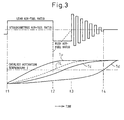
- FIG. 3 is a time chart showing the change in combustion air-fuel ratio at the time of the above-mentioned startup and the change in temperature at the different parts of the three-way catalyst apparatus 1.
- the combustion air-fuel ratio is made lean and the temperature of the exhaust upstream part of the three-way catalyst apparatus 1 is raised.
- the temperature TL at the position of the length L in the longitudinal direction from the exhaust upstream end serving as the boundary of the exhaust upstream part of the three-way catalyst apparatus 1 reaches the catalyst activation temperature T, so from this time t2, the combustion air-fuel ratio is made rich to suppress the amount of production of NOx in the cylinders and the exhaust downstream part of the three-way catalyst apparatus 1 is made to rise in temperature well.
- the maximum O 2 storage amount of oxygen stored in the three-way catalyst apparatus 1 at the time of a lean air-fuel ratio operation is reduced to about half by the rich air-fuel ratio operation.
- the engine is operated to make the combustion air-fuel ratio alternately fluctuate to the rich side and lean side from the stoichiometric air-fuel ratio. Due to this, the O 2 storage amount of the three-way catalyst apparatus 1 is maintained at about half of the maximum storage amount and simultaneously the part of the exhaust downstream part of the three-way catalyst apparatus 1 still not raised to the catalyst activation temperature is raised in temperature well by burning the relatively large amounts of HC and CO.
- the amplitude of the fluctuating air-fuel ratio in this operation is made smaller the higher the temperature Td of the exhaust downstream end of the three-way catalyst apparatus 1 to keep the exhaust upstream part etc. of the three-way catalyst apparatus 1 already raised to the catalyst activation temperature from being excessively raised in temperature.
- the temperature Td of the exhaust downstream end of the three-way catalyst apparatus 1 also becomes the catalyst activation temperature T, that is, the three-way catalyst apparatus 1 as a whole becomes the catalyst activation temperature T or more, so the air-fuel ratio control at the time of startup for raising the temperature of the three-way catalyst apparatus 1 is stopped.
- the amount of HC and amount of CO supplied to the three-way catalyst apparatus 1 from the time t2 to t3 are important.
- the amount of exhaust gas during this time is greater than or less than the amount of exhaust gas forming the standard for setting these values, the rich air-fuel ratio at the time of switching has to be changed to the lean side or rich side, the time t between the time t2 to t3 has to be shortened or lengthened, or the change per unit time of the combustion air-fuel ratio has to be increased or decreased.
- the above-mentioned air-fuel ratio control was performed at the time of engine startup, but of course when it is judged that the cooling water temperature is high and the time is the time of restart right after the engine is stopped, the three-way catalyst apparatus 1 as a whole becomes the catalyst activation temperature, so the above-mentioned air-fuel ratio control does not have to be performed. Further, when it is judged that the cooling water temperature is abnormally low and the time is the time of startup at an extremely low temperature, the operation under the lean air-fuel ratio right after completion of engine startup becomes unstable, so the above-mentioned air-fuel ratio control can be foregone.
- the temperature TL at the position of the length L from the exhaust upstream end of the three-way catalyst apparatus 1 was estimated using at least the temperature Tc of the center of the three-way catalyst apparatus 1 in the longitudinal direction measured by the second temperature sensor 3, but it is also possible to estimate this without providing any temperature sensor based on an amount of energy for raising the temperature of the three-way catalyst apparatus 1 estimated from the temperature of the exhaust gas and flow rate of the exhaust gas flowing into the three-way catalyst apparatus 1 for each engine operating state and on the outside air temperature etc.
- the three-way catalyst apparatus 1 is considered to have a temperature gradient gradually decreasing from the exhaust upstream end to the exhaust downstream end.
- the temperature Td of the exhaust downstream end of the three-way catalyst apparatus 1 may also be estimated without providing a temperature sensor based on the above-mentioned amount of energy and outside air temperature.
Landscapes
- Engineering & Computer Science (AREA)
- Chemical & Material Sciences (AREA)
- Chemical Kinetics & Catalysis (AREA)
- Combustion & Propulsion (AREA)
- Mechanical Engineering (AREA)
- General Engineering & Computer Science (AREA)
- Health & Medical Sciences (AREA)
- Toxicology (AREA)
- Materials Engineering (AREA)
- Exhaust Gas After Treatment (AREA)
- Electrical Control Of Air Or Fuel Supplied To Internal-Combustion Engine (AREA)
- Combined Controls Of Internal Combustion Engines (AREA)
Applications Claiming Priority (2)
| Application Number | Priority Date | Filing Date | Title |
|---|---|---|---|
| JP2006029535A JP4363406B2 (ja) | 2006-02-07 | 2006-02-07 | 内燃機関の空燃比制御装置 |
| PCT/JP2007/052549 WO2007091721A1 (ja) | 2006-02-07 | 2007-02-07 | 内燃機関の空燃比制御装置 |
Publications (1)
| Publication Number | Publication Date |
|---|---|
| EP1983181A1 true EP1983181A1 (de) | 2008-10-22 |
Family
ID=38345307
Family Applications (1)
| Application Number | Title | Priority Date | Filing Date |
|---|---|---|---|
| EP07714129A Withdrawn EP1983181A1 (de) | 2006-02-07 | 2007-02-07 | Steuerung des kraftstoff-luft-verhältnisses für einen verbrennungsmotor |
Country Status (5)
| Country | Link |
|---|---|
| US (1) | US7729847B2 (de) |
| EP (1) | EP1983181A1 (de) |
| JP (1) | JP4363406B2 (de) |
| CN (1) | CN101313137B (de) |
| WO (1) | WO2007091721A1 (de) |
Cited By (1)
| Publication number | Priority date | Publication date | Assignee | Title |
|---|---|---|---|---|
| EP2492477A4 (de) * | 2009-10-23 | 2015-07-29 | Toyota Motor Co Ltd | Steuerung des kraftstoff-luft-verhältnisses für einen verbrennungsmotor |
Families Citing this family (19)
| Publication number | Priority date | Publication date | Assignee | Title |
|---|---|---|---|---|
| JP4728301B2 (ja) | 2007-08-14 | 2011-07-20 | 株式会社エヌ・ティ・ティ・ドコモ | ユーザ装置、送信方法、及び通信システム |
| US8448422B2 (en) * | 2007-11-12 | 2013-05-28 | Ford Global Technologies, Llc | Engine starting control for engine with hydrocarbon retaining system |
| JP5061861B2 (ja) * | 2007-11-21 | 2012-10-31 | トヨタ自動車株式会社 | 内燃機関の制御装置 |
| JP4883319B2 (ja) * | 2008-01-11 | 2012-02-22 | 三菱自動車工業株式会社 | 筒内噴射型内燃機関の排気浄化装置 |
| DE102009016191B4 (de) * | 2009-04-03 | 2013-04-04 | Alstom Technology Ltd. | Verfahren und Anordnung zur Verbesserung des dynamischen Verhaltens eines kohlegefeuerten Kraftwerkes bei primären und/oder sekundären Anforderungen des Elektrizitätsnetz-Betreibers an die Stromabgabe in das Netz |
| CN102667116A (zh) * | 2009-10-23 | 2012-09-12 | 丰田自动车株式会社 | 内燃机的空燃比控制装置 |
| CN102713182B (zh) * | 2010-01-14 | 2014-04-09 | 丰田自动车株式会社 | 催化剂温度控制装置 |
| US8863505B2 (en) * | 2010-04-26 | 2014-10-21 | GM Global Technology Operations LLC | Start-stop hybrid exothermic catalyst heating system |
| CN102933807B (zh) * | 2010-05-20 | 2015-04-29 | 丰田自动车株式会社 | 内燃机的排气净化装置 |
| DE102010037924B4 (de) * | 2010-10-01 | 2020-02-20 | Ford Global Technologies, Llc. | Verfahren zur Steuerung einer Abgasnachbehandlungseinrichtung eines Hybridantriebs |
| JP2012225266A (ja) * | 2011-04-20 | 2012-11-15 | Toyota Motor Corp | 内燃機関の制御装置 |
| US8769932B2 (en) * | 2011-10-13 | 2014-07-08 | GM Global Technology Operations LLC | Cold start NO2 generation system |
| US20140356237A1 (en) * | 2012-02-07 | 2014-12-04 | Toyota Jidosha Kabushiki Kaisha | Exhaust gas purification apparatus for internal combustion engine |
| JPWO2013118252A1 (ja) * | 2012-02-07 | 2015-05-11 | トヨタ自動車株式会社 | 内燃機関の排気浄化装置 |
| US9157391B2 (en) * | 2013-03-14 | 2015-10-13 | EMIT Technologies, Inc. | Systems and methods for controlling a combustion engine |
| DE102013221595A1 (de) * | 2013-10-24 | 2015-04-30 | Robert Bosch Gmbh | Verfahren und Vorrichtung zur Verminderung der Emissionen einer Brennkraftmaschine |
| GB2560303B (en) * | 2017-02-24 | 2019-10-16 | Jaguar Land Rover Ltd | Exhaust gas treatment system and method |
| DE102017107678A1 (de) * | 2017-04-10 | 2018-10-11 | Volkswagen Aktiengesellschaft | Verfahren zur Inbetriebnahme eines Verbrennungsmotors und Kraftfahrzeug mit einem Verbrennungsmotor |
| CN113606075A (zh) * | 2021-08-25 | 2021-11-05 | 联合汽车电子有限公司 | 混合动力汽车发动机起动状态的检测方法、装置及存储介质 |
Family Cites Families (26)
| Publication number | Priority date | Publication date | Assignee | Title |
|---|---|---|---|---|
| JPH03164549A (ja) * | 1989-11-22 | 1991-07-16 | Fuji Heavy Ind Ltd | 2サイクルエンジンのエンジン制御装置 |
| JP2727801B2 (ja) * | 1991-07-03 | 1998-03-18 | 三菱自動車工業株式会社 | エンジンの制御方法及びその制御装置 |
| US5584176A (en) * | 1994-12-23 | 1996-12-17 | Ford Motor Company | Engine control to achieve rapid catalyst warm-up |
| JP3309669B2 (ja) | 1995-10-02 | 2002-07-29 | 日産自動車株式会社 | 内燃機関の二次空気供給装置 |
| JP3550839B2 (ja) | 1995-12-01 | 2004-08-04 | 日産自動車株式会社 | 内燃機関の制御装置 |
| JP3564847B2 (ja) | 1996-02-15 | 2004-09-15 | 日産自動車株式会社 | エンジンの排気浄化装置 |
| JP3337931B2 (ja) * | 1997-01-30 | 2002-10-28 | マツダ株式会社 | 筒内噴射式エンジン |
| JP3551348B2 (ja) * | 1997-06-19 | 2004-08-04 | 日産自動車株式会社 | 排気ガス浄化装置 |
| US6131439A (en) * | 1998-05-28 | 2000-10-17 | Ford Global Technologies, Inc. | Catalyst deterioration detection with sensor calibration |
| JP3370957B2 (ja) * | 1998-09-18 | 2003-01-27 | トヨタ自動車株式会社 | 内燃機関の排気浄化装置 |
| JP2000257479A (ja) | 1999-03-09 | 2000-09-19 | Mitsubishi Electric Corp | 内燃機関の触媒昇温制御装置 |
| JP2001050085A (ja) | 1999-08-03 | 2001-02-23 | Honda Motor Co Ltd | 内燃機関の燃料供給制御装置 |
| JP4543473B2 (ja) | 2000-01-20 | 2010-09-15 | マツダ株式会社 | エンジンの排気浄化装置 |
| JP4506003B2 (ja) * | 2001-02-27 | 2010-07-21 | マツダ株式会社 | エンジンの排気浄化装置 |
| JP2002332833A (ja) * | 2001-05-10 | 2002-11-22 | Mitsubishi Automob Eng Co Ltd | 多気筒エンジンの排気浄化装置 |
| ES2326959T3 (es) * | 2001-06-18 | 2009-10-22 | Toyota Jidosha Kabushiki Kaisha | Un aparato de control de la relacion aire-combustible para un motor de combustion interna. |
| JP3855920B2 (ja) * | 2002-11-29 | 2006-12-13 | トヨタ自動車株式会社 | 内燃機関の排気浄化装置 |
| JP4325264B2 (ja) | 2003-04-23 | 2009-09-02 | トヨタ自動車株式会社 | 内燃機関の空燃比制御装置 |
| JP2004339967A (ja) | 2003-05-14 | 2004-12-02 | Nissan Motor Co Ltd | エンジンの排気ガス浄化装置 |
| JP2004346777A (ja) | 2003-05-20 | 2004-12-09 | Fuji Heavy Ind Ltd | エンジンの空燃比制御装置 |
| JP4062231B2 (ja) * | 2003-10-16 | 2008-03-19 | トヨタ自動車株式会社 | 内燃機関の排気浄化装置 |
| JP4120563B2 (ja) * | 2003-11-06 | 2008-07-16 | トヨタ自動車株式会社 | 内燃機関の排気浄化装置 |
| JP4155192B2 (ja) | 2003-12-26 | 2008-09-24 | トヨタ自動車株式会社 | 内燃機関の排気浄化装置 |
| JP2005264826A (ja) | 2004-03-18 | 2005-09-29 | Mitsubishi Motors Corp | 内燃機関の排気浄化装置 |
| US20050223698A1 (en) * | 2004-03-31 | 2005-10-13 | Mitsubishi Fuso Truck And Bus Corporation | Exhaust gas cleaning device |
| JP2006348753A (ja) * | 2005-06-13 | 2006-12-28 | Mitsubishi Motors Corp | エンジンの排ガス浄化装置 |
-
2006
- 2006-02-07 JP JP2006029535A patent/JP4363406B2/ja not_active Expired - Fee Related
-
2007
- 2007-02-07 WO PCT/JP2007/052549 patent/WO2007091721A1/ja not_active Ceased
- 2007-02-07 CN CN2007800002698A patent/CN101313137B/zh not_active Expired - Fee Related
- 2007-02-07 EP EP07714129A patent/EP1983181A1/de not_active Withdrawn
- 2007-02-07 US US11/913,697 patent/US7729847B2/en not_active Expired - Fee Related
Non-Patent Citations (1)
| Title |
|---|
| See references of WO2007091721A1 * |
Cited By (1)
| Publication number | Priority date | Publication date | Assignee | Title |
|---|---|---|---|---|
| EP2492477A4 (de) * | 2009-10-23 | 2015-07-29 | Toyota Motor Co Ltd | Steuerung des kraftstoff-luft-verhältnisses für einen verbrennungsmotor |
Also Published As
| Publication number | Publication date |
|---|---|
| US7729847B2 (en) | 2010-06-01 |
| JP2007211598A (ja) | 2007-08-23 |
| CN101313137A (zh) | 2008-11-26 |
| WO2007091721A1 (ja) | 2007-08-16 |
| CN101313137B (zh) | 2011-03-30 |
| JP4363406B2 (ja) | 2009-11-11 |
| US20090301437A1 (en) | 2009-12-10 |
Similar Documents
| Publication | Publication Date | Title |
|---|---|---|
| US7729847B2 (en) | Air-fuel ratio control device of internal combustion engine | |
| JP3649188B2 (ja) | 排気浄化装置付き内燃機関 | |
| CN105041494B (zh) | 内燃机的控制装置 | |
| JP6323281B2 (ja) | 内燃機関の制御装置 | |
| JP2010013974A (ja) | フィルタの再生システム及びフィルタの再生方法 | |
| JP2011163229A (ja) | 多気筒内燃機関の気筒間空燃比インバランス判定装置 | |
| CN105899789B (zh) | 内燃发动机的控制系统 | |
| US8484951B2 (en) | Internal combustion engine | |
| JP5664884B2 (ja) | 内燃機関の空燃比制御装置 | |
| JP4400633B2 (ja) | 内燃機関の制御システム | |
| JP5326969B2 (ja) | 内燃機関の燃料供給量制御装置 | |
| JP3776299B2 (ja) | 内燃機関の排気浄化装置 | |
| JP6773422B2 (ja) | 内燃機関の排気浄化システム | |
| JP2004308494A (ja) | ヒータの制御装置 | |
| JP6156310B2 (ja) | 内燃機関の制御装置 | |
| JP3540989B2 (ja) | 内燃機関の排気浄化装置 | |
| JP2016031050A (ja) | 内燃機関の排気浄化装置 | |
| JP2008019792A (ja) | 内燃機関の触媒早期暖機制御装置 | |
| JP5690182B2 (ja) | 内燃機関の制御装置 | |
| JP5679210B2 (ja) | 排ガス浄化装置および排ガス浄化方法 | |
| JP3676641B2 (ja) | 酸素濃度センサの故障判定装置 | |
| JP6327240B2 (ja) | 内燃機関の制御装置 | |
| JP4792444B2 (ja) | 排ガス浄化装置の昇温制御装置 | |
| JP3591403B2 (ja) | 内燃機関の触媒昇温装置 | |
| JP2008064111A (ja) | 内燃機関の排気浄化装置 |
Legal Events
| Date | Code | Title | Description |
|---|---|---|---|
| PUAI | Public reference made under article 153(3) epc to a published international application that has entered the european phase |
Free format text: ORIGINAL CODE: 0009012 |
|
| 17P | Request for examination filed |
Effective date: 20080131 |
|
| AK | Designated contracting states |
Kind code of ref document: A1 Designated state(s): DE FR |
|
| RBV | Designated contracting states (corrected) |
Designated state(s): DE FR |
|
| DAX | Request for extension of the european patent (deleted) | ||
| RAP1 | Party data changed (applicant data changed or rights of an application transferred) |
Owner name: TOYOTA JIDOSHA KABUSHIKI KAISHA |
|
| STAA | Information on the status of an ep patent application or granted ep patent |
Free format text: STATUS: THE APPLICATION HAS BEEN WITHDRAWN |
|
| 18W | Application withdrawn |
Effective date: 20140219 |