EP1980858B1 - Crucible shuttle assembly and method of operation - Google Patents
Crucible shuttle assembly and method of operation Download PDFInfo
- Publication number
- EP1980858B1 EP1980858B1 EP08103244.3A EP08103244A EP1980858B1 EP 1980858 B1 EP1980858 B1 EP 1980858B1 EP 08103244 A EP08103244 A EP 08103244A EP 1980858 B1 EP1980858 B1 EP 1980858B1
- Authority
- EP
- European Patent Office
- Prior art keywords
- crucible
- arms
- gripping
- shuttle
- head
- Prior art date
- Legal status (The legal status is an assumption and is not a legal conclusion. Google has not performed a legal analysis and makes no representation as to the accuracy of the status listed.)
- Not-in-force
Links
- 238000000034 method Methods 0.000 title description 4
- NJPPVKZQTLUDBO-UHFFFAOYSA-N novaluron Chemical compound C1=C(Cl)C(OC(F)(F)C(OC(F)(F)F)F)=CC=C1NC(=O)NC(=O)C1=C(F)C=CC=C1F NJPPVKZQTLUDBO-UHFFFAOYSA-N 0.000 description 32
- 230000006698 induction Effects 0.000 description 10
- 238000010586 diagram Methods 0.000 description 3
- 230000007246 mechanism Effects 0.000 description 3
- 238000002485 combustion reaction Methods 0.000 description 2
- 230000008878 coupling Effects 0.000 description 2
- 238000010168 coupling process Methods 0.000 description 2
- 238000005859 coupling reaction Methods 0.000 description 2
- 238000007599 discharging Methods 0.000 description 2
- 230000002441 reversible effect Effects 0.000 description 2
- OKTJSMMVPCPJKN-UHFFFAOYSA-N Carbon Chemical compound [C] OKTJSMMVPCPJKN-UHFFFAOYSA-N 0.000 description 1
- 229910000831 Steel Inorganic materials 0.000 description 1
- NINIDFKCEFEMDL-UHFFFAOYSA-N Sulfur Chemical compound [S] NINIDFKCEFEMDL-UHFFFAOYSA-N 0.000 description 1
- 239000004809 Teflon Substances 0.000 description 1
- 229920006362 Teflon® Polymers 0.000 description 1
- 208000027418 Wounds and injury Diseases 0.000 description 1
- 238000013459 approach Methods 0.000 description 1
- 229910052799 carbon Inorganic materials 0.000 description 1
- 230000006835 compression Effects 0.000 description 1
- 238000007906 compression Methods 0.000 description 1
- 230000006378 damage Effects 0.000 description 1
- 238000000151 deposition Methods 0.000 description 1
- 230000009977 dual effect Effects 0.000 description 1
- 230000006872 improvement Effects 0.000 description 1
- 208000014674 injury Diseases 0.000 description 1
- 230000002093 peripheral effect Effects 0.000 description 1
- 230000008569 process Effects 0.000 description 1
- 238000007789 sealing Methods 0.000 description 1
- 239000010959 steel Substances 0.000 description 1
- 229910052717 sulfur Inorganic materials 0.000 description 1
- 239000011593 sulfur Substances 0.000 description 1
- 238000005303 weighing Methods 0.000 description 1
Images


Classifications
-
- G—PHYSICS
- G01—MEASURING; TESTING
- G01N—INVESTIGATING OR ANALYSING MATERIALS BY DETERMINING THEIR CHEMICAL OR PHYSICAL PROPERTIES
- G01N35/00—Automatic analysis not limited to methods or materials provided for in any single one of groups G01N1/00 - G01N33/00; Handling materials therefor
- G01N35/0099—Automatic analysis not limited to methods or materials provided for in any single one of groups G01N1/00 - G01N33/00; Handling materials therefor comprising robots or similar manipulators
-
- B—PERFORMING OPERATIONS; TRANSPORTING
- B65—CONVEYING; PACKING; STORING; HANDLING THIN OR FILAMENTARY MATERIAL
- B65G—TRANSPORT OR STORAGE DEVICES, e.g. CONVEYORS FOR LOADING OR TIPPING, SHOP CONVEYOR SYSTEMS OR PNEUMATIC TUBE CONVEYORS
- B65G47/00—Article or material-handling devices associated with conveyors; Methods employing such devices
- B65G47/74—Feeding, transfer, or discharging devices of particular kinds or types
- B65G47/90—Devices for picking-up and depositing articles or materials
- B65G47/907—Devices for picking-up and depositing articles or materials with at least two picking-up heads
-
- F—MECHANICAL ENGINEERING; LIGHTING; HEATING; WEAPONS; BLASTING
- F27—FURNACES; KILNS; OVENS; RETORTS
- F27B—FURNACES, KILNS, OVENS OR RETORTS IN GENERAL; OPEN SINTERING OR LIKE APPARATUS
- F27B17/00—Furnaces of a kind not covered by any of groups F27B1/00 - F27B15/00
- F27B17/02—Furnaces of a kind not covered by any of groups F27B1/00 - F27B15/00 specially designed for laboratory use
-
- F—MECHANICAL ENGINEERING; LIGHTING; HEATING; WEAPONS; BLASTING
- F27—FURNACES; KILNS; OVENS; RETORTS
- F27D—DETAILS OR ACCESSORIES OF FURNACES, KILNS, OVENS OR RETORTS, IN SO FAR AS THEY ARE OF KINDS OCCURRING IN MORE THAN ONE KIND OF FURNACE
- F27D3/00—Charging; Discharging; Manipulation of charge
-
- F—MECHANICAL ENGINEERING; LIGHTING; HEATING; WEAPONS; BLASTING
- F27—FURNACES; KILNS; OVENS; RETORTS
- F27D—DETAILS OR ACCESSORIES OF FURNACES, KILNS, OVENS OR RETORTS, IN SO FAR AS THEY ARE OF KINDS OCCURRING IN MORE THAN ONE KIND OF FURNACE
- F27D99/00—Subject matter not provided for in other groups of this subclass
- F27D99/0001—Heating elements or systems
- F27D99/0006—Electric heating elements or system
- F27D2099/0015—Induction heating
-
- Y—GENERAL TAGGING OF NEW TECHNOLOGICAL DEVELOPMENTS; GENERAL TAGGING OF CROSS-SECTIONAL TECHNOLOGIES SPANNING OVER SEVERAL SECTIONS OF THE IPC; TECHNICAL SUBJECTS COVERED BY FORMER USPC CROSS-REFERENCE ART COLLECTIONS [XRACs] AND DIGESTS
- Y02—TECHNOLOGIES OR APPLICATIONS FOR MITIGATION OR ADAPTATION AGAINST CLIMATE CHANGE
- Y02P—CLIMATE CHANGE MITIGATION TECHNOLOGIES IN THE PRODUCTION OR PROCESSING OF GOODS
- Y02P10/00—Technologies related to metal processing
- Y02P10/25—Process efficiency
Definitions
- the present invention relates to a crucible loading/unloading assembly for efficiently moving crucibles onto and from the pedestal of an analyzer furnace.
- Analyzers are used in the steel industry inter alia for determining the content of carbon and/or sulfur.
- Such analyzers include, for example, Model No. CS600 which is commercially available from Leco Corporation of St. Joseph, Michigan.
- Model No. CS600 which is commercially available from Leco Corporation of St. Joseph, Michigan.
- several systems have been designed to provide automatic loading and unloading of crucibles into such furnaces to provide more efficient throughput of samples.
- One such system is represented in, for example, U.S. Patent No. 4,238,450 .
- sample combustion boats have been the subject of auto-loading, as shown in U.S. Patent No. 5,395,586 .
- U.S. Patent Publication 2003/0175156 also discloses yet another crucible loading system.
- TW1274034 discloses a multidirectional gripping apparatus comprising a pair of opposed gripping arms supported by a rotating head.
- a gripping assembly for holding and releasing crucibles comprising:
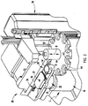
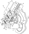
- FIG. 1 there is shown an analyzer 10, such as a Model No. CS600, commercially available from Leco Corporation of St. Joseph, Michigan.
- the analyzer includes an induction furnace 11 and the crucible loading/unloading shuttle assembly 20 of the present invention.
- Induction furnace 11 includes a crucible-holding pedestal 12, which moves vertically upwardly and downwardly as indicated by arrow A in Fig. 3 , to introduce a sample-holding crucible 14 into the furnace for the combustion of and analysis of a specimen held therein.
- the pedestal is shown in its lowered position in Figs. 1 and 3-5 .
- a plurality of crucibles 14 each have preloaded and preweighed samples 13 (shown in phantom in Fig.
- a vertical sample loading station 50 which may include up to six tiers of crucible-holding disks 44, each including ten crucible-holding sockets.
- the disks 44 are mounted in vertically spaced relationship on a vertically extending rotary axle 52 which can be raised and lowered, as shown by arrow B in Figs. 1 and 2 , to position a crucible, such as crucible 14' ( Fig. 2 ) to a position to be picked up by gripper arms 26 of shuttle assembly 20.
- a crucible such as crucible 14' ( Fig. 2 )
- the disk 44 aligned with the shuttle 16 of shuttle assembly 20 rotates to place the next crucible in position to be picked up.
- the shaft 52 is raised by a hydraulic, electric, or pneumatic cylinder 45 ( Fig. 1 ) to position the next fully loaded disk 44 in position to dispense crucibles to shuttle 16.
- the shuttle assembly 20 includes, as best seen in Figs. 2-5 and 7 , a shuttle 16 with a rotary head 22 to which opposed pairs 24, 26 of spring-loaded, curved facing opposed gripping arms are mounted.
- Each pair of arms includes arms 25, 27 (best seen in Fig. 7 ), which are curved to circumscribe opposite sides of a cylindrical crucible 14 to hold crucibles in the shuttle 16 as it linearly moves between the sample loading station 50 in a direction indicated by arrow C in Figs. 1 and 2 toward and away from furnace pedestal 12.
- Each of the arms 25, 27 are pivotally mounted to the top 121 of housing 21 ( Fig. 8A ) of rotary head 22 by pivot pins 23 ( Figs. 7 and 8 ).
- Springs 23' are coupled between each arm 25, 27 over posts 29 at a location spaced from their pivot connection to housing 21 of rotary head 22 to urge arms 25, 27 together for gripping the crucibles. The details of the operation of the gripping arms are described below.
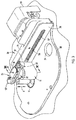
- the shuttle 16 is mounted to a carriage 130 ( Figs 7-10 ) for its linear movement between a new crucible picking position ( Fig. 2 ) to the induction furnace pedestal 12, as shown in Fig. 3 .
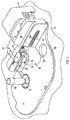
- the gripping arms 25, 27 are sequentially actuated to open and pick up the spent crucible 14'' as shown in Fig 3 whereupon the rotary head 22 rotates, as shown by arrow D in Fig. 4 , to position the newly picked up crucible 14' onto the pedestal 12, as shown in Fig. 5 .
- the shuttle 16 moves from the position shown in Figs. 3-4 to the intermediate position shown in Fig.
- a sample loaded new crucible 14' such as shown in Fig. 2 is picked up by the pair of arms 26 which are opened as described below as the shuttle 16 moves to the loading station 50 to pick up a new sample-holding crucible 14'.
- the arms are then closed to grip the crucible, and disk 44 is lowered to eliminate any contact between crucible 14' and disk 44.
- the crucible is removed from the slotted holding aperture 43 ( Fig. 2 ) in the crucible-holding disk 44 of loading station 50.
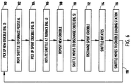
- the shuttle then moves toward the pedestal 12 as seen by block 102 in Fig 6 and as it approaches the pedestal with the arms 24 facing the pedestal, the arms are opened to circumscribe a spent crucible on the pedestal which has been lowered automatically from the furnace 11 after an analysis has been completed.
- the arms 24 then close around the spent crucible 14'' and the carriage 130, and rotary head 22 is raised, as described below, to lift the spent crucible 14'' off of the pedestal 12 as shown by block 104.
- the rotary head 22 of shuttle 16 is then rotated 180°, as illustrated in Fig. 4 and represented by block 106.
- the new crucible 14' is aligned over the pedestal 12 and the rotary head and carriage is lowered to place the crucible 14' on the pedestal at which time arms 26 are opened to deposit the new crucible on the pedestal as shown by block 108.
- the shuttle moves to align the spent crucible 14'' over the discharge chute 28 in base plate 58.
- the pair of arms 24 are then opened to drop crucible 14'' down chute 28 for disposal as seen by block 112.
- the rotary head 22 of shuttle 16 is then rotated 180° again to position the pair of arms 26 in a position facing crucible loading station 50 as seen by block 114 and the arms are opened as the shuttle moves to the crucible loading station as shown by block 116 into the position shown in Fig. 2 .
- the crucible handling sequence is then repeated until all of the crucibles holding samples to be analyzed have been sequentially introduced into the analyzer 10 and an analysis run on the samples.
- the sequence shown in Fig. 6 is programmed into the microprocessor 72 which is part of the control circuit 70 described below in conjunction with Fig. 13 .
- the pairs of gripper arms 24 and 26, each comprising arms 25 and 27, are opened against the force of tension springs 23' holding the arms in a crucible-holding position (shown in Figs. 3 and 4 ) by pneumatically actuated, conical actuator pistons 100, as seen in Fig. 7 and best seen in Figs. 8 and 8A .
- Springs 23' have ends fitted over posts 29 in arms 25 and 27, as best seen in Fig. 7 , to place them in tension.
- Pistons 100 extend between the pivot arms 25 and 27 at a location between the pivot pins 23 and the spring-holding posts 29.
- Pistons 100 have a body 102 which is disk shaped and has a peripheral sealing o-ring 109 to movably and sealably mount the pistons within pneumatic cylinders 107 in the rotary head 22.
- the top 121 ( Figs. 8 and 8A ) of rotary head 22 includes a removable cover 105 enclosing pistons 100.
- Cover 105 has apertures 106 which allow the integral conical tips 103 on the upper side of pistons 100 to extend through head 22, when actuated, to urge pairs of arms 24, 26 to an open crucible releasing position. Tips 103, as seen in Fig. 8A , engage the inner edges 31 of arms 25, 27 acting as a wedge to open the arms to a crucible receiving or releasing position.
- Pneumatic pressure is selectively applied to each of the piston cylinders 107 and pistons 100 by means of controlled supply lines 108, 110 ( Fig 8 ). Pistons 100 are returned to a lowered position by compression springs 101 extending between cover 105 ( Figs. 8 and 8A ) and the body 102 of the pistons.
- the pneumatic connection to the pistons 100, as well as the electrical coupling to a rotary actuator 120 (discussed below), is made by a pneumatic and electrical flexible umbilical 46 ( Figs. 9 and 10 ), which is coupled at one end to shuttle 16 to provide electrical control signals to a rotary actuator 120 and pneumatic pressure individually to pistons 100.
- Umbilical 46 is allowed to move with the shuttle and is held in an out-of-the-way position from the shuttle drive screw 134 by means of a horizontally extending guide rail 112, as seen in Figs. 9 and 10 .
- the fixed end of umbilical 46 is coupled to housing 54 by a mounting block 74.
- the electrical and pneumatic conduits in umbilical 46 are then conventionally coupled to the pneumatic and electrical supplies.
- a rotary actuator 120 having a vertically extending rotary drive shaft 122 ( Figs. 8-10 ) coupled to head 22 for reversibly rotating head 22 of shuttle 16 through an arc of 180°.
- the rotary actuator 120 rotates the rotary head 22 180° in one direction and then reverses direction, such that one pair of gripping arms 26 always handles a new crucible, while the opposite pair of gripping arms 24 handle the contaminated or spent crucibles.
- the pivoting connections 23 of the pairs of arms 24, 26 are protected by a cover 36 ( Figs. 2-5 ) by a fastener 37 extending into a vertical post 38, in turn, threaded into a center threaded socket 39 of rotary head 22 ( Fig. 8 ).
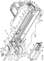
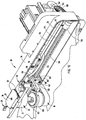
- the shuttle 16 is mounted to a carriage 130 having a polymeric guide block 132 mounted within carriage mounting plate 133 ( Fig. 9 ).
- the lower surface of carriage mounting plate 133 includes a Teflon ® pad 137 which slides along the floor 42 of housing 54.
- the rotating drive screw 134 is surrounded by an elongated guide 144 secured to back wall 55 of housing 54 by fasteners 41.
- Guide 144 has an internal bore for receiving drive screw 134 and rotatably supporting the drive screw along its length.
- the guide 144 also externally slideably receives guide block 132 (as best seen in Fig.
- the guide block surrounds linear drive screw 134 supported within housing 54 at an end opposite guide block 132 by bearing 135 supported on the back wall 55 of housing 54.
- the guide block includes a drive nut 134' ( Fig. 9A ), which drives block 132 and carriage 130 secured thereto by fasteners 141 ( Fig. 9 ) to move the shuttle 16.
- Elements 132, 134, 135, and 144 can be a commercially available device, such as a rapid drive screw, available from Kerk Motion Products, Inc.
- the end of drive screw 134 extends through bearing 135 and is coupled to a gear 136 rotatably driven by a toothed drive belt 138 (best seen in Fig. 9 ).
- Belt 138 extends through a slot 139 ( Fig. 11 ) in housing 54 and is coupled to a reversible drive motor 140 through a gear 142 for the reversible rotation of drive screw 134, resulting in the linear movement of carriage 130 between the pedestal 12 and the sample loader 50.
- the housing 54 for the shuttle assembly 20 includes a front cover plate 56 ( Figs 1, 3-5, and 7 ) with a horizontally extending slot 57 to allow an arm 131 (best seen in Fig. 9 ) coupling shuttle 16 to carriage plate 133 to engage the drive screw 134 throughout the range of movement of the shuttle 16.
- the shuttle assembly 20, including shuttle 16 with its rotary head 22, gripping arm pairs 24, 26, the shuttle drive mechanism within housing 54, and motor 140, is pivotally mounted to a fixed base plate 58 to be pivotally raised and lowered in a direction indicated by arrow E in Fig. 11 for lifting and placing a crucible from the pairs of arms 24, 26 onto and from the pedestal 12.
- the mounting housing 54, within which carriage 130 and its drive mechanism are mounted are pivotally mounted about a pivot axle 150 ( Fig. 12 ).
- Axle 150 includes a section 151 which extends through an aperture 152 in a mounting block 154.
- Block 154 is secured by fasteners 156 to the lower surface 56 of plate 58 adjacent an aperture 59 in plate 58.
- Axle 150 has an end 153 which extends into a threaded aperture 162 in a T-shaped pivot block 160 which is secure to the outer bottom surface 62 of housing 54 by fasteners 164 extending into threaded sockets 64.
- Block 160 extends through aperture 59 when housing 54 is attached to base plate 58.
- Aperture 162 in block 160 aligns with aperture 152 in adjacent block 154.
- a linear actuator 170 is mounted in spaced relationship to pivot pin 150 and has a linearly movable shaft 172 which engages the lower surface 62 of housing 54 through opening 53 in base plate 58.
- Actuator 170 is secured to the underside 56 of plate 58 by a mounting bracket 174 and threaded fasteners 176 ( Fig. 12 ).
- housing 54 pivots upwardly raising the carriage 130 and shutter 16 with gripping arm pairs 24 and 26 upwardly a distance sufficient to lift a crucible off of the pedestal 12.
- the rotating head 22 lifts to pick up a spent crucible and rotates and then lowers to deposit a new crucible on pedestal 12. It then moves and opens to discharge the spent crucible into discharge chute 28.
- Plate 58 as seen in Figs. 3 , 4 , 11 , and 12 , includes a slotted aperture 15 for surrounding the furnace pedestal 12 and is secured to the frame 18 ( Fig. 1 ) of furnace 11 in a conventional manner.
- Motor 140 is enclosed by a suitable cover 32 ( Figs. 3-5, 10, and 11 ).
- Fig. 13 is a block electrical diagram of a control circuit 70 for controlling the shuttle assembly 20 in its sequence of operation as described above with reference to Fig. 6 .
- Circuit 70 includes a microprocessor 72 and suitable memory and interface circuits which couple to the drive motor 140 and linear actuator 170 for raising, lowering, and transporting crucibles.
- Circuit 70 also provides timed signals to rotary actuator 120 to rotate the rotary head 22 of shuttle 16.
- Microprocessor 72 also actuates the solenoid valves 71 and 73 for actuating the pneumatic supply to control pistons 100
- control circuit 70 can be incorporated into the overall control for the instrument 10 and furnace 11 with which the crucible loading and unloading system is mounted including the control of the sample loading station 50.
- sample-holding crucibles can be picked up from a loading station, transported to the induction furnace pedestal whereupon a spent crucible is picked up, the assembly rotated to deposit a new crucible onto the induction furnace pedestal and moved to an intermediate position for discharging the spent crucible and subsequently rotated and moved again to the loading station.
- the throughput of sample-holding crucibles is greatly improved.
- This mechanism can also be used for moving crucibles or other articles between first and second positions.
- a similar crucible handling assembly can be used to load crucibles onto station 50 from a sample weighing balance.
Landscapes
- Engineering & Computer Science (AREA)
- Mechanical Engineering (AREA)
- Health & Medical Sciences (AREA)
- General Engineering & Computer Science (AREA)
- Chemical & Material Sciences (AREA)
- Pathology (AREA)
- Physics & Mathematics (AREA)
- Life Sciences & Earth Sciences (AREA)
- Robotics (AREA)
- Analytical Chemistry (AREA)
- Biochemistry (AREA)
- General Health & Medical Sciences (AREA)
- General Physics & Mathematics (AREA)
- Immunology (AREA)
- Clinical Laboratory Science (AREA)
- Sampling And Sample Adjustment (AREA)
- Investigating Or Analyzing Non-Biological Materials By The Use Of Chemical Means (AREA)
- Automatic Analysis And Handling Materials Therefor (AREA)
Applications Claiming Priority (2)
| Application Number | Priority Date | Filing Date | Title |
|---|---|---|---|
| US91132007P | 2007-04-12 | 2007-04-12 | |
| US12/055,880 US8323565B2 (en) | 2007-04-12 | 2008-03-26 | Crucible shuttle assembly and method of operation |
Publications (3)
| Publication Number | Publication Date |
|---|---|
| EP1980858A2 EP1980858A2 (en) | 2008-10-15 |
| EP1980858A3 EP1980858A3 (en) | 2014-09-24 |
| EP1980858B1 true EP1980858B1 (en) | 2016-03-30 |
Family
ID=39642716
Family Applications (1)
| Application Number | Title | Priority Date | Filing Date |
|---|---|---|---|
| EP08103244.3A Not-in-force EP1980858B1 (en) | 2007-04-12 | 2008-03-31 | Crucible shuttle assembly and method of operation |
Country Status (3)
| Country | Link |
|---|---|
| US (3) | US8323565B2 (enExample) |
| EP (1) | EP1980858B1 (enExample) |
| JP (1) | JP5027719B2 (enExample) |
Families Citing this family (19)
| Publication number | Priority date | Publication date | Assignee | Title |
|---|---|---|---|---|
| US8323565B2 (en) | 2007-04-12 | 2012-12-04 | Leco Corporation | Crucible shuttle assembly and method of operation |
| EP2078961B1 (de) * | 2008-01-08 | 2020-04-08 | Liconic Ag | Vorrichtung zum Manipulieren von Laborproben |
| WO2012044816A2 (en) * | 2010-09-30 | 2012-04-05 | Gt Advanced Technologies Inc. | Method and system for centering a crucible in furnace |
| US8592695B2 (en) * | 2010-11-30 | 2013-11-26 | Jose Maria Las Navas Garcia | Stackable crucible, a system using a stackable crucible, and a method of using a stackable crucible |
| WO2013016035A1 (en) * | 2011-07-22 | 2013-01-31 | Constitution Medical, Inc. | Sample transport systems and methods |
| HU228711B1 (en) * | 2011-08-22 | 2013-05-28 | Diagon Kft | Method and apparatus for feeding cuvetta comprising assay and reagent |
| CN102419378B (zh) * | 2011-11-25 | 2013-07-03 | 长沙开元仪器股份有限公司 | 智能移样装置 |
| EP2951519B1 (en) * | 2013-01-31 | 2018-08-29 | IMP Group (Pty) Ltd. | A furnace for preparing fused (homogenised) samples for sample analysis |
| USD771167S1 (en) | 2013-08-21 | 2016-11-08 | A.L.M.T. Corp. | Crucible |
| JP6149805B2 (ja) * | 2014-06-05 | 2017-06-21 | 株式会社ダイフク | 搬送装置 |
| CN104793005A (zh) * | 2015-04-02 | 2015-07-22 | 常州大学 | 空间三自由度的坩埚输送机器人 |
| EP3270166A1 (de) * | 2016-07-11 | 2018-01-17 | Siemens Healthcare Diagnostics Products GmbH | Greifvorrichtung zum transport von flüssigkeitsbehältern in einem automatischen analysegerät |
| KR101858848B1 (ko) * | 2016-12-12 | 2018-05-17 | 주식회사 포스코 | 도가니 이송장치 |
| KR101867718B1 (ko) * | 2016-12-14 | 2018-06-14 | 주식회사 포스코 | 도가니 이송장치 |
| CN107571274A (zh) * | 2017-08-16 | 2018-01-12 | 洛阳理工学院 | 一种用于环形加热炉装取料装置的夹料钳 |
| CN110238811B (zh) * | 2019-06-14 | 2020-09-29 | 温州大学激光与光电智能制造研究院 | 智能送料机器人 |
| JP7326113B2 (ja) | 2019-10-31 | 2023-08-15 | 株式会社日立ハイテク | 検体容器把持装置及び検体搬送装置、接続装置 |
| CN111996584A (zh) * | 2020-07-13 | 2020-11-27 | 大同新成新材料股份有限公司 | 一种单晶炉半导体石墨坩埚提升装置 |
| CN113200340A (zh) * | 2021-03-31 | 2021-08-03 | 山东华滋自动化技术股份有限公司 | 一种盘类件用上料装置 |
Family Cites Families (27)
| Publication number | Priority date | Publication date | Assignee | Title |
|---|---|---|---|---|
| US4238450A (en) * | 1979-02-21 | 1980-12-09 | Leco Corporation | Crucible loading-unloading system |
| JPS5848858A (ja) * | 1981-09-17 | 1983-03-22 | Horiba Ltd | 自動金属分析装置 |
| US4573910A (en) * | 1982-03-05 | 1986-03-04 | Leco Corporation | Carbon, hydrogen, and nitrogen analyzer |
| JPS61189457A (ja) * | 1985-02-19 | 1986-08-23 | Nippon Kokan Kk <Nkk> | 石炭類自動工業分析用ロボツトハンド |
| GB2185458A (en) | 1986-01-13 | 1987-07-22 | Mars Inc | Gripper mechanism |
| US5585068A (en) * | 1990-02-20 | 1996-12-17 | Biochemical Diagnostics, Inc. | Apparatus for automatically separating a compound from a plurality of discrete liquid specimens |
| US5314662A (en) * | 1993-03-08 | 1994-05-24 | Leco Corporation | Sample autoloader for use with an analytical combustion furnace |
| JPH0751559A (ja) * | 1993-08-20 | 1995-02-28 | Rigoushiya:Kk | 液体試料の分配秤量装置 |
| US5441891A (en) * | 1994-05-26 | 1995-08-15 | Burkovich; Robert A. | Transfer mechanism within an incubator |
| US5948360A (en) | 1994-07-11 | 1999-09-07 | Tekmar Company | Autosampler with robot arm |
| JPH1048194A (ja) * | 1996-08-03 | 1998-02-20 | Horiba Ltd | 元素分析装置 |
| JPH1048200A (ja) * | 1996-08-03 | 1998-02-20 | Horiba Ltd | 元素分析装置 |
| JP3616464B2 (ja) * | 1996-08-03 | 2005-02-02 | 株式会社堀場製作所 | 元素分析装置 |
| US6024925A (en) | 1997-01-23 | 2000-02-15 | Sequenom, Inc. | Systems and methods for preparing low volume analyte array elements |
| US6117391A (en) * | 1998-06-18 | 2000-09-12 | Bayer Corporation | Cup handling subsystem for an automated clinical chemistry analyzer system |
| FI113703B (fi) * | 1999-03-12 | 2004-05-31 | Innotrac Diagnostics Oy | Diagnostinen mittauslaite |
| US7390458B2 (en) | 2000-10-13 | 2008-06-24 | Irm Llc | High throughput processing system and method of using |
| US6592324B2 (en) | 2001-02-26 | 2003-07-15 | Irm, Llc | Gripper mechanism |
| US20030164200A1 (en) | 2001-03-16 | 2003-09-04 | American Controls, Inc. | Assembly line fluid filling system and method |
| JP4342951B2 (ja) * | 2002-03-11 | 2009-10-14 | レコ コーポレイション | 坩堝と試料を自動的に装填するシステム及び方法 |
| ES2372387T3 (es) | 2003-05-30 | 2012-01-19 | Moffett Research And Development Limited | Una carretilla elevadora montada en camión con mástil de elevación libre de doble efecto. |
| US7695239B2 (en) * | 2003-07-14 | 2010-04-13 | Fortrend Engineering Corporation | End effector gripper arms having corner grippers which reorient reticle during transfer |
| US7694583B2 (en) | 2005-05-05 | 2010-04-13 | Control Gaging, Inc. | Gripper gage assembly |
| JP5119377B2 (ja) * | 2005-09-26 | 2013-01-16 | キアゲン ゲゼルシャフト ミット ベシュレンクテル ハフツング | 生物試料を処理するための装置 |
| TWI274034B (en) * | 2006-03-15 | 2007-02-21 | Mjc Probe Inc | Multi-directional gripping apparatus |
| US8657550B2 (en) | 2007-04-12 | 2014-02-25 | Leco Corporation | Crucible shuttle assembly with linearly moving carriage |
| US8323565B2 (en) | 2007-04-12 | 2012-12-04 | Leco Corporation | Crucible shuttle assembly and method of operation |
-
2008
- 2008-03-26 US US12/055,880 patent/US8323565B2/en active Active
- 2008-03-31 EP EP08103244.3A patent/EP1980858B1/en not_active Not-in-force
- 2008-04-11 JP JP2008103120A patent/JP5027719B2/ja not_active Expired - Fee Related
-
2012
- 2012-09-12 US US13/611,855 patent/US9039342B2/en active Active
-
2015
- 2015-01-15 US US14/597,820 patent/US9470701B2/en active Active
Also Published As
| Publication number | Publication date |
|---|---|
| US20130004277A1 (en) | 2013-01-03 |
| US20080253870A1 (en) | 2008-10-16 |
| EP1980858A2 (en) | 2008-10-15 |
| EP1980858A3 (en) | 2014-09-24 |
| US9470701B2 (en) | 2016-10-18 |
| JP5027719B2 (ja) | 2012-09-19 |
| US9039342B2 (en) | 2015-05-26 |
| US8323565B2 (en) | 2012-12-04 |
| JP2008292465A (ja) | 2008-12-04 |
| US20150125247A1 (en) | 2015-05-07 |
Similar Documents
| Publication | Publication Date | Title |
|---|---|---|
| EP1980858B1 (en) | Crucible shuttle assembly and method of operation | |
| EP1455175B1 (en) | Mixed sample moisture or ash analyzer | |
| US8657550B2 (en) | Crucible shuttle assembly with linearly moving carriage | |
| EP0615127B1 (en) | Sample autoloader | |
| CN102398267B (zh) | 手和机器人 | |
| JP2002536667A (ja) | 形状記憶金属アクチュエータからなるグリッパーを備えた自動サンプリング器 | |
| CA2539935A1 (en) | High throughput automated seed analysis system | |
| JP2008292465A5 (enExample) | ||
| WO2005073108A1 (en) | Slide feeder with air bearing conveyor | |
| EA006151B1 (ru) | Манипулятор, печь и способ обработки изделия в печи в процессе осуществления способа количественного анализа | |
| CN101868731A (zh) | 用来封闭生物材料容器的设备 | |
| US8910687B2 (en) | Device for placing histological and biological samples | |
| CN111157332A (zh) | 一种用于全自动钢筋拉伸试验试件的储供料仓 | |
| CN115321169A (zh) | 一种料仓输送结构 | |
| CN109603950B (zh) | 一种试剂瓶夹持组件、自动加载机构及其加载方法 | |
| JP3873982B2 (ja) | 蓋付きマイクロプレートの供給装置 | |
| JP3873983B2 (ja) | マイクロプレートの供給装置 | |
| US20260009744A1 (en) | Sample changer for x-ray devices | |
| EP4675264A1 (en) | Sample changer for x-ray devices | |
| CN218917247U (zh) | 一种用于岩石热解综合分析的自动进样装置 | |
| CN223229621U (zh) | 一种水泥胶砂试件存储传输装置 | |
| JP7292098B2 (ja) | 検体用トレイと検体検査自動化システム | |
| CN209835583U (zh) | 容器换盖设备 | |
| CN210401117U (zh) | 煤炭水分分析系统 | |
| GB2080232A (en) | Crucible loading-unloading apparatus |
Legal Events
| Date | Code | Title | Description |
|---|---|---|---|
| PUAI | Public reference made under article 153(3) epc to a published international application that has entered the european phase |
Free format text: ORIGINAL CODE: 0009012 |
|
| AK | Designated contracting states |
Kind code of ref document: A2 Designated state(s): AT BE BG CH CY CZ DE DK EE ES FI FR GB GR HR HU IE IS IT LI LT LU LV MC MT NL NO PL PT RO SE SI SK TR |
|
| AX | Request for extension of the european patent |
Extension state: AL BA MK RS |
|
| PUAL | Search report despatched |
Free format text: ORIGINAL CODE: 0009013 |
|
| AK | Designated contracting states |
Kind code of ref document: A3 Designated state(s): AT BE BG CH CY CZ DE DK EE ES FI FR GB GR HR HU IE IS IT LI LT LU LV MC MT NL NO PL PT RO SE SI SK TR |
|
| AX | Request for extension of the european patent |
Extension state: AL BA MK RS |
|
| RIC1 | Information provided on ipc code assigned before grant |
Ipc: G01N 35/04 20060101AFI20140820BHEP Ipc: B25J 15/00 20060101ALI20140820BHEP Ipc: G01N 35/00 20060101ALI20140820BHEP Ipc: G01N 33/20 20060101ALI20140820BHEP Ipc: B65G 47/00 20060101ALI20140820BHEP Ipc: F27D 3/00 20060101ALI20140820BHEP |
|
| 17P | Request for examination filed |
Effective date: 20150310 |
|
| RBV | Designated contracting states (corrected) |
Designated state(s): AT BE BG CH CY CZ DE DK EE ES FI FR GB GR HR HU IE IS IT LI LT LU LV MC MT NL NO PL PT RO SE SI SK TR |
|
| RBV | Designated contracting states (corrected) |
Designated state(s): AT BE BG CH CY CZ DE DK EE ES FI FR GB GR HR HU IE IS IT LI LT LU LV MC MT NL NO PL PT RO SE SI SK TR |
|
| AKX | Designation fees paid |
Designated state(s): AT BE BG CH CY CZ DE DK EE ES FI FR GB GR HR HU IE IS IT LI LT LU LV MC MT NL NO PL PT RO SE SI SK TR |
|
| AXX | Extension fees paid |
Extension state: RS Extension state: AL Extension state: MK Extension state: BA |
|
| GRAP | Despatch of communication of intention to grant a patent |
Free format text: ORIGINAL CODE: EPIDOSNIGR1 |
|
| INTG | Intention to grant announced |
Effective date: 20151001 |
|
| GRAS | Grant fee paid |
Free format text: ORIGINAL CODE: EPIDOSNIGR3 |
|
| GRAA | (expected) grant |
Free format text: ORIGINAL CODE: 0009210 |
|
| AK | Designated contracting states |
Kind code of ref document: B1 Designated state(s): AT BE BG CH CY CZ DE DK EE ES FI FR GB GR HR HU IE IS IT LI LT LU LV MC MT NL NO PL PT RO SE SI SK TR |
|
| REG | Reference to a national code |
Ref country code: GB Ref legal event code: FG4D |
|
| REG | Reference to a national code |
Ref country code: CH Ref legal event code: EP |
|
| REG | Reference to a national code |
Ref country code: AT Ref legal event code: REF Ref document number: 785945 Country of ref document: AT Kind code of ref document: T Effective date: 20160415 |
|
| REG | Reference to a national code |
Ref country code: IE Ref legal event code: FG4D |
|
| REG | Reference to a national code |
Ref country code: DE Ref legal event code: R096 Ref document number: 602008043142 Country of ref document: DE |
|
| REG | Reference to a national code |
Ref country code: LT Ref legal event code: MG4D |
|
| PG25 | Lapsed in a contracting state [announced via postgrant information from national office to epo] |
Ref country code: FI Free format text: LAPSE BECAUSE OF FAILURE TO SUBMIT A TRANSLATION OF THE DESCRIPTION OR TO PAY THE FEE WITHIN THE PRESCRIBED TIME-LIMIT Effective date: 20160330 Ref country code: HR Free format text: LAPSE BECAUSE OF FAILURE TO SUBMIT A TRANSLATION OF THE DESCRIPTION OR TO PAY THE FEE WITHIN THE PRESCRIBED TIME-LIMIT Effective date: 20160330 Ref country code: NO Free format text: LAPSE BECAUSE OF FAILURE TO SUBMIT A TRANSLATION OF THE DESCRIPTION OR TO PAY THE FEE WITHIN THE PRESCRIBED TIME-LIMIT Effective date: 20160630 Ref country code: GR Free format text: LAPSE BECAUSE OF FAILURE TO SUBMIT A TRANSLATION OF THE DESCRIPTION OR TO PAY THE FEE WITHIN THE PRESCRIBED TIME-LIMIT Effective date: 20160701 |
|
| REG | Reference to a national code |
Ref country code: NL Ref legal event code: MP Effective date: 20160330 |
|
| REG | Reference to a national code |
Ref country code: AT Ref legal event code: MK05 Ref document number: 785945 Country of ref document: AT Kind code of ref document: T Effective date: 20160330 |
|
| PG25 | Lapsed in a contracting state [announced via postgrant information from national office to epo] |
Ref country code: LT Free format text: LAPSE BECAUSE OF FAILURE TO SUBMIT A TRANSLATION OF THE DESCRIPTION OR TO PAY THE FEE WITHIN THE PRESCRIBED TIME-LIMIT Effective date: 20160330 Ref country code: SE Free format text: LAPSE BECAUSE OF FAILURE TO SUBMIT A TRANSLATION OF THE DESCRIPTION OR TO PAY THE FEE WITHIN THE PRESCRIBED TIME-LIMIT Effective date: 20160330 Ref country code: BE Free format text: LAPSE BECAUSE OF NON-PAYMENT OF DUE FEES Effective date: 20160331 Ref country code: LV Free format text: LAPSE BECAUSE OF FAILURE TO SUBMIT A TRANSLATION OF THE DESCRIPTION OR TO PAY THE FEE WITHIN THE PRESCRIBED TIME-LIMIT Effective date: 20160330 |
|
| PG25 | Lapsed in a contracting state [announced via postgrant information from national office to epo] |
Ref country code: NL Free format text: LAPSE BECAUSE OF FAILURE TO SUBMIT A TRANSLATION OF THE DESCRIPTION OR TO PAY THE FEE WITHIN THE PRESCRIBED TIME-LIMIT Effective date: 20160330 |
|
| PG25 | Lapsed in a contracting state [announced via postgrant information from national office to epo] |
Ref country code: PL Free format text: LAPSE BECAUSE OF FAILURE TO SUBMIT A TRANSLATION OF THE DESCRIPTION OR TO PAY THE FEE WITHIN THE PRESCRIBED TIME-LIMIT Effective date: 20160330 Ref country code: IS Free format text: LAPSE BECAUSE OF FAILURE TO SUBMIT A TRANSLATION OF THE DESCRIPTION OR TO PAY THE FEE WITHIN THE PRESCRIBED TIME-LIMIT Effective date: 20160730 Ref country code: EE Free format text: LAPSE BECAUSE OF FAILURE TO SUBMIT A TRANSLATION OF THE DESCRIPTION OR TO PAY THE FEE WITHIN THE PRESCRIBED TIME-LIMIT Effective date: 20160330 |
|
| REG | Reference to a national code |
Ref country code: CH Ref legal event code: PL |
|
| PG25 | Lapsed in a contracting state [announced via postgrant information from national office to epo] |
Ref country code: SK Free format text: LAPSE BECAUSE OF FAILURE TO SUBMIT A TRANSLATION OF THE DESCRIPTION OR TO PAY THE FEE WITHIN THE PRESCRIBED TIME-LIMIT Effective date: 20160330 Ref country code: ES Free format text: LAPSE BECAUSE OF FAILURE TO SUBMIT A TRANSLATION OF THE DESCRIPTION OR TO PAY THE FEE WITHIN THE PRESCRIBED TIME-LIMIT Effective date: 20160330 Ref country code: RO Free format text: LAPSE BECAUSE OF FAILURE TO SUBMIT A TRANSLATION OF THE DESCRIPTION OR TO PAY THE FEE WITHIN THE PRESCRIBED TIME-LIMIT Effective date: 20160330 Ref country code: PT Free format text: LAPSE BECAUSE OF FAILURE TO SUBMIT A TRANSLATION OF THE DESCRIPTION OR TO PAY THE FEE WITHIN THE PRESCRIBED TIME-LIMIT Effective date: 20160801 Ref country code: CZ Free format text: LAPSE BECAUSE OF FAILURE TO SUBMIT A TRANSLATION OF THE DESCRIPTION OR TO PAY THE FEE WITHIN THE PRESCRIBED TIME-LIMIT Effective date: 20160330 Ref country code: AT Free format text: LAPSE BECAUSE OF FAILURE TO SUBMIT A TRANSLATION OF THE DESCRIPTION OR TO PAY THE FEE WITHIN THE PRESCRIBED TIME-LIMIT Effective date: 20160330 |
|
| REG | Reference to a national code |
Ref country code: IE Ref legal event code: MM4A |
|
| PG25 | Lapsed in a contracting state [announced via postgrant information from national office to epo] |
Ref country code: IT Free format text: LAPSE BECAUSE OF FAILURE TO SUBMIT A TRANSLATION OF THE DESCRIPTION OR TO PAY THE FEE WITHIN THE PRESCRIBED TIME-LIMIT Effective date: 20160330 Ref country code: BE Free format text: LAPSE BECAUSE OF FAILURE TO SUBMIT A TRANSLATION OF THE DESCRIPTION OR TO PAY THE FEE WITHIN THE PRESCRIBED TIME-LIMIT Effective date: 20160330 |
|
| REG | Reference to a national code |
Ref country code: DE Ref legal event code: R097 Ref document number: 602008043142 Country of ref document: DE |
|
| PG25 | Lapsed in a contracting state [announced via postgrant information from national office to epo] |
Ref country code: LI Free format text: LAPSE BECAUSE OF NON-PAYMENT OF DUE FEES Effective date: 20160331 Ref country code: DK Free format text: LAPSE BECAUSE OF FAILURE TO SUBMIT A TRANSLATION OF THE DESCRIPTION OR TO PAY THE FEE WITHIN THE PRESCRIBED TIME-LIMIT Effective date: 20160330 Ref country code: IE Free format text: LAPSE BECAUSE OF NON-PAYMENT OF DUE FEES Effective date: 20160331 Ref country code: CH Free format text: LAPSE BECAUSE OF NON-PAYMENT OF DUE FEES Effective date: 20160331 |
|
| PLBE | No opposition filed within time limit |
Free format text: ORIGINAL CODE: 0009261 |
|
| STAA | Information on the status of an ep patent application or granted ep patent |
Free format text: STATUS: NO OPPOSITION FILED WITHIN TIME LIMIT |
|
| GBPC | Gb: european patent ceased through non-payment of renewal fee |
Effective date: 20160630 |
|
| 26N | No opposition filed |
Effective date: 20170103 |
|
| REG | Reference to a national code |
Ref country code: FR Ref legal event code: ST Effective date: 20170203 |
|
| PG25 | Lapsed in a contracting state [announced via postgrant information from national office to epo] |
Ref country code: FR Free format text: LAPSE BECAUSE OF NON-PAYMENT OF DUE FEES Effective date: 20160530 |
|
| PG25 | Lapsed in a contracting state [announced via postgrant information from national office to epo] |
Ref country code: SI Free format text: LAPSE BECAUSE OF FAILURE TO SUBMIT A TRANSLATION OF THE DESCRIPTION OR TO PAY THE FEE WITHIN THE PRESCRIBED TIME-LIMIT Effective date: 20160330 Ref country code: GB Free format text: LAPSE BECAUSE OF NON-PAYMENT OF DUE FEES Effective date: 20160630 |
|
| PG25 | Lapsed in a contracting state [announced via postgrant information from national office to epo] |
Ref country code: MT Free format text: LAPSE BECAUSE OF FAILURE TO SUBMIT A TRANSLATION OF THE DESCRIPTION OR TO PAY THE FEE WITHIN THE PRESCRIBED TIME-LIMIT Effective date: 20160330 |
|
| PG25 | Lapsed in a contracting state [announced via postgrant information from national office to epo] |
Ref country code: HU Free format text: LAPSE BECAUSE OF FAILURE TO SUBMIT A TRANSLATION OF THE DESCRIPTION OR TO PAY THE FEE WITHIN THE PRESCRIBED TIME-LIMIT; INVALID AB INITIO Effective date: 20080331 Ref country code: CY Free format text: LAPSE BECAUSE OF FAILURE TO SUBMIT A TRANSLATION OF THE DESCRIPTION OR TO PAY THE FEE WITHIN THE PRESCRIBED TIME-LIMIT Effective date: 20160330 |
|
| PG25 | Lapsed in a contracting state [announced via postgrant information from national office to epo] |
Ref country code: MC Free format text: LAPSE BECAUSE OF FAILURE TO SUBMIT A TRANSLATION OF THE DESCRIPTION OR TO PAY THE FEE WITHIN THE PRESCRIBED TIME-LIMIT Effective date: 20160330 Ref country code: LU Free format text: LAPSE BECAUSE OF NON-PAYMENT OF DUE FEES Effective date: 20160331 Ref country code: TR Free format text: LAPSE BECAUSE OF FAILURE TO SUBMIT A TRANSLATION OF THE DESCRIPTION OR TO PAY THE FEE WITHIN THE PRESCRIBED TIME-LIMIT Effective date: 20160330 |
|
| PG25 | Lapsed in a contracting state [announced via postgrant information from national office to epo] |
Ref country code: BG Free format text: LAPSE BECAUSE OF FAILURE TO SUBMIT A TRANSLATION OF THE DESCRIPTION OR TO PAY THE FEE WITHIN THE PRESCRIBED TIME-LIMIT Effective date: 20160330 |
|
| PGFP | Annual fee paid to national office [announced via postgrant information from national office to epo] |
Ref country code: DE Payment date: 20220210 Year of fee payment: 15 |
|
| REG | Reference to a national code |
Ref country code: DE Ref legal event code: R119 Ref document number: 602008043142 Country of ref document: DE |
|
| PG25 | Lapsed in a contracting state [announced via postgrant information from national office to epo] |
Ref country code: DE Free format text: LAPSE BECAUSE OF NON-PAYMENT OF DUE FEES Effective date: 20231003 |