EP1974893A2 - Apparareil pour thermoformer des pièces avec imprimees à la surface - Google Patents
Apparareil pour thermoformer des pièces avec imprimees à la surface Download PDFInfo
- Publication number
- EP1974893A2 EP1974893A2 EP08012435A EP08012435A EP1974893A2 EP 1974893 A2 EP1974893 A2 EP 1974893A2 EP 08012435 A EP08012435 A EP 08012435A EP 08012435 A EP08012435 A EP 08012435A EP 1974893 A2 EP1974893 A2 EP 1974893A2
- Authority
- EP
- European Patent Office
- Prior art keywords
- mold
- mold half
- vacuum
- layer
- heating
- Prior art date
- Legal status (The legal status is an assumption and is not a legal conclusion. Google has not performed a legal analysis and makes no representation as to the accuracy of the status listed.)
- Withdrawn
Links
Images


Classifications
-
- B—PERFORMING OPERATIONS; TRANSPORTING
- B29—WORKING OF PLASTICS; WORKING OF SUBSTANCES IN A PLASTIC STATE IN GENERAL
- B29C—SHAPING OR JOINING OF PLASTICS; SHAPING OF MATERIAL IN A PLASTIC STATE, NOT OTHERWISE PROVIDED FOR; AFTER-TREATMENT OF THE SHAPED PRODUCTS, e.g. REPAIRING
- B29C59/00—Surface shaping of articles, e.g. embossing; Apparatus therefor
- B29C59/02—Surface shaping of articles, e.g. embossing; Apparatus therefor by mechanical means, e.g. pressing
- B29C59/026—Surface shaping of articles, e.g. embossing; Apparatus therefor by mechanical means, e.g. pressing of layered or coated substantially flat surfaces
-
- B—PERFORMING OPERATIONS; TRANSPORTING
- B29—WORKING OF PLASTICS; WORKING OF SUBSTANCES IN A PLASTIC STATE IN GENERAL
- B29C—SHAPING OR JOINING OF PLASTICS; SHAPING OF MATERIAL IN A PLASTIC STATE, NOT OTHERWISE PROVIDED FOR; AFTER-TREATMENT OF THE SHAPED PRODUCTS, e.g. REPAIRING
- B29C37/00—Component parts, details, accessories or auxiliary operations, not covered by group B29C33/00 or B29C35/00
- B29C37/0025—Applying surface layers, e.g. coatings, decorative layers, printed layers, to articles during shaping, e.g. in-mould printing
- B29C37/0028—In-mould coating, e.g. by introducing the coating material into the mould after forming the article
- B29C37/0032—In-mould coating, e.g. by introducing the coating material into the mould after forming the article the coating being applied upon the mould surface before introducing the moulding compound, e.g. applying a gelcoat
-
- B—PERFORMING OPERATIONS; TRANSPORTING
- B29—WORKING OF PLASTICS; WORKING OF SUBSTANCES IN A PLASTIC STATE IN GENERAL
- B29C—SHAPING OR JOINING OF PLASTICS; SHAPING OF MATERIAL IN A PLASTIC STATE, NOT OTHERWISE PROVIDED FOR; AFTER-TREATMENT OF THE SHAPED PRODUCTS, e.g. REPAIRING
- B29C43/00—Compression moulding, i.e. applying external pressure to flow the moulding material; Apparatus therefor
- B29C43/02—Compression moulding, i.e. applying external pressure to flow the moulding material; Apparatus therefor of articles of definite length, i.e. discrete articles
- B29C43/18—Compression moulding, i.e. applying external pressure to flow the moulding material; Apparatus therefor of articles of definite length, i.e. discrete articles incorporating preformed parts or layers, e.g. compression moulding around inserts or for coating articles
- B29C43/183—Compression moulding, i.e. applying external pressure to flow the moulding material; Apparatus therefor of articles of definite length, i.e. discrete articles incorporating preformed parts or layers, e.g. compression moulding around inserts or for coating articles the preformed layer being a lining, e.g. shaped in the mould before compression moulding, or a preformed shell adapted to the shape of the mould
-
- B—PERFORMING OPERATIONS; TRANSPORTING
- B29—WORKING OF PLASTICS; WORKING OF SUBSTANCES IN A PLASTIC STATE IN GENERAL
- B29C—SHAPING OR JOINING OF PLASTICS; SHAPING OF MATERIAL IN A PLASTIC STATE, NOT OTHERWISE PROVIDED FOR; AFTER-TREATMENT OF THE SHAPED PRODUCTS, e.g. REPAIRING
- B29C43/00—Compression moulding, i.e. applying external pressure to flow the moulding material; Apparatus therefor
- B29C43/32—Component parts, details or accessories; Auxiliary operations
- B29C43/36—Moulds for making articles of definite length, i.e. discrete articles
-
- B—PERFORMING OPERATIONS; TRANSPORTING
- B29—WORKING OF PLASTICS; WORKING OF SUBSTANCES IN A PLASTIC STATE IN GENERAL
- B29C—SHAPING OR JOINING OF PLASTICS; SHAPING OF MATERIAL IN A PLASTIC STATE, NOT OTHERWISE PROVIDED FOR; AFTER-TREATMENT OF THE SHAPED PRODUCTS, e.g. REPAIRING
- B29C51/00—Shaping by thermoforming, i.e. shaping sheets or sheet like preforms after heating, e.g. shaping sheets in matched moulds or by deep-drawing; Apparatus therefor
- B29C51/14—Shaping by thermoforming, i.e. shaping sheets or sheet like preforms after heating, e.g. shaping sheets in matched moulds or by deep-drawing; Apparatus therefor using multilayered preforms or sheets
-
- B—PERFORMING OPERATIONS; TRANSPORTING
- B29—WORKING OF PLASTICS; WORKING OF SUBSTANCES IN A PLASTIC STATE IN GENERAL
- B29C—SHAPING OR JOINING OF PLASTICS; SHAPING OF MATERIAL IN A PLASTIC STATE, NOT OTHERWISE PROVIDED FOR; AFTER-TREATMENT OF THE SHAPED PRODUCTS, e.g. REPAIRING
- B29C51/00—Shaping by thermoforming, i.e. shaping sheets or sheet like preforms after heating, e.g. shaping sheets in matched moulds or by deep-drawing; Apparatus therefor
- B29C51/26—Component parts, details or accessories; Auxiliary operations
- B29C51/42—Heating or cooling
- B29C51/421—Heating or cooling of preforms, specially adapted for thermoforming
- B29C51/422—Heating or cooling of preforms, specially adapted for thermoforming to produce a temperature differential
- B29C51/423—Heating or cooling of preforms, specially adapted for thermoforming to produce a temperature differential through the thickness of the preform
-
- B—PERFORMING OPERATIONS; TRANSPORTING
- B29—WORKING OF PLASTICS; WORKING OF SUBSTANCES IN A PLASTIC STATE IN GENERAL
- B29C—SHAPING OR JOINING OF PLASTICS; SHAPING OF MATERIAL IN A PLASTIC STATE, NOT OTHERWISE PROVIDED FOR; AFTER-TREATMENT OF THE SHAPED PRODUCTS, e.g. REPAIRING
- B29C43/00—Compression moulding, i.e. applying external pressure to flow the moulding material; Apparatus therefor
- B29C43/32—Component parts, details or accessories; Auxiliary operations
- B29C43/34—Feeding the material to the mould or the compression means
- B29C2043/3405—Feeding the material to the mould or the compression means using carrying means
- B29C2043/3411—Feeding the material to the mould or the compression means using carrying means mounted onto arms, e.g. grippers, fingers, clamping frame, suction means
-
- B—PERFORMING OPERATIONS; TRANSPORTING
- B29—WORKING OF PLASTICS; WORKING OF SUBSTANCES IN A PLASTIC STATE IN GENERAL
- B29C—SHAPING OR JOINING OF PLASTICS; SHAPING OF MATERIAL IN A PLASTIC STATE, NOT OTHERWISE PROVIDED FOR; AFTER-TREATMENT OF THE SHAPED PRODUCTS, e.g. REPAIRING
- B29C43/00—Compression moulding, i.e. applying external pressure to flow the moulding material; Apparatus therefor
- B29C43/32—Component parts, details or accessories; Auxiliary operations
- B29C43/36—Moulds for making articles of definite length, i.e. discrete articles
- B29C2043/3602—Moulds for making articles of definite length, i.e. discrete articles with means for positioning, fastening or clamping the material to be formed or preforms inside the mould
-
- B—PERFORMING OPERATIONS; TRANSPORTING
- B29—WORKING OF PLASTICS; WORKING OF SUBSTANCES IN A PLASTIC STATE IN GENERAL
- B29C—SHAPING OR JOINING OF PLASTICS; SHAPING OF MATERIAL IN A PLASTIC STATE, NOT OTHERWISE PROVIDED FOR; AFTER-TREATMENT OF THE SHAPED PRODUCTS, e.g. REPAIRING
- B29C2791/00—Shaping characteristics in general
- B29C2791/001—Shaping in several steps
-
- B—PERFORMING OPERATIONS; TRANSPORTING
- B29—WORKING OF PLASTICS; WORKING OF SUBSTANCES IN A PLASTIC STATE IN GENERAL
- B29C—SHAPING OR JOINING OF PLASTICS; SHAPING OF MATERIAL IN A PLASTIC STATE, NOT OTHERWISE PROVIDED FOR; AFTER-TREATMENT OF THE SHAPED PRODUCTS, e.g. REPAIRING
- B29C2791/00—Shaping characteristics in general
- B29C2791/004—Shaping under special conditions
- B29C2791/006—Using vacuum
-
- B—PERFORMING OPERATIONS; TRANSPORTING
- B29—WORKING OF PLASTICS; WORKING OF SUBSTANCES IN A PLASTIC STATE IN GENERAL
- B29C—SHAPING OR JOINING OF PLASTICS; SHAPING OF MATERIAL IN A PLASTIC STATE, NOT OTHERWISE PROVIDED FOR; AFTER-TREATMENT OF THE SHAPED PRODUCTS, e.g. REPAIRING
- B29C2791/00—Shaping characteristics in general
- B29C2791/004—Shaping under special conditions
- B29C2791/007—Using fluid under pressure
-
- B—PERFORMING OPERATIONS; TRANSPORTING
- B29—WORKING OF PLASTICS; WORKING OF SUBSTANCES IN A PLASTIC STATE IN GENERAL
- B29C—SHAPING OR JOINING OF PLASTICS; SHAPING OF MATERIAL IN A PLASTIC STATE, NOT OTHERWISE PROVIDED FOR; AFTER-TREATMENT OF THE SHAPED PRODUCTS, e.g. REPAIRING
- B29C2949/00—Indexing scheme relating to blow-moulding
- B29C2949/30—Preforms or parisons made of several components
- B29C2949/3086—Interaction between two or more components, e.g. type of or lack of bonding
- B29C2949/3094—Interaction between two or more components, e.g. type of or lack of bonding preform having at least partially loose components, e.g. at least partially loose layers
-
- B—PERFORMING OPERATIONS; TRANSPORTING
- B29—WORKING OF PLASTICS; WORKING OF SUBSTANCES IN A PLASTIC STATE IN GENERAL
- B29C—SHAPING OR JOINING OF PLASTICS; SHAPING OF MATERIAL IN A PLASTIC STATE, NOT OTHERWISE PROVIDED FOR; AFTER-TREATMENT OF THE SHAPED PRODUCTS, e.g. REPAIRING
- B29C43/00—Compression moulding, i.e. applying external pressure to flow the moulding material; Apparatus therefor
-
- B—PERFORMING OPERATIONS; TRANSPORTING
- B29—WORKING OF PLASTICS; WORKING OF SUBSTANCES IN A PLASTIC STATE IN GENERAL
- B29C—SHAPING OR JOINING OF PLASTICS; SHAPING OF MATERIAL IN A PLASTIC STATE, NOT OTHERWISE PROVIDED FOR; AFTER-TREATMENT OF THE SHAPED PRODUCTS, e.g. REPAIRING
- B29C51/00—Shaping by thermoforming, i.e. shaping sheets or sheet like preforms after heating, e.g. shaping sheets in matched moulds or by deep-drawing; Apparatus therefor
- B29C51/16—Lining or labelling
-
- B—PERFORMING OPERATIONS; TRANSPORTING
- B29—WORKING OF PLASTICS; WORKING OF SUBSTANCES IN A PLASTIC STATE IN GENERAL
- B29C—SHAPING OR JOINING OF PLASTICS; SHAPING OF MATERIAL IN A PLASTIC STATE, NOT OTHERWISE PROVIDED FOR; AFTER-TREATMENT OF THE SHAPED PRODUCTS, e.g. REPAIRING
- B29C51/00—Shaping by thermoforming, i.e. shaping sheets or sheet like preforms after heating, e.g. shaping sheets in matched moulds or by deep-drawing; Apparatus therefor
- B29C51/26—Component parts, details or accessories; Auxiliary operations
- B29C51/261—Handling means, e.g. transfer means, feeding means
- B29C51/262—Clamping means for the sheets, e.g. clamping frames
-
- B—PERFORMING OPERATIONS; TRANSPORTING
- B29—WORKING OF PLASTICS; WORKING OF SUBSTANCES IN A PLASTIC STATE IN GENERAL
- B29K—INDEXING SCHEME ASSOCIATED WITH SUBCLASSES B29B, B29C OR B29D, RELATING TO MOULDING MATERIALS OR TO MATERIALS FOR MOULDS, REINFORCEMENTS, FILLERS OR PREFORMED PARTS, e.g. INSERTS
- B29K2105/00—Condition, form or state of moulded material or of the material to be shaped
- B29K2105/04—Condition, form or state of moulded material or of the material to be shaped cellular or porous
-
- B—PERFORMING OPERATIONS; TRANSPORTING
- B29—WORKING OF PLASTICS; WORKING OF SUBSTANCES IN A PLASTIC STATE IN GENERAL
- B29L—INDEXING SCHEME ASSOCIATED WITH SUBCLASS B29C, RELATING TO PARTICULAR ARTICLES
- B29L2009/00—Layered products
- B29L2009/001—Layered products the layers being loose
-
- B—PERFORMING OPERATIONS; TRANSPORTING
- B29—WORKING OF PLASTICS; WORKING OF SUBSTANCES IN A PLASTIC STATE IN GENERAL
- B29L—INDEXING SCHEME ASSOCIATED WITH SUBCLASS B29C, RELATING TO PARTICULAR ARTICLES
- B29L2031/00—Other particular articles
- B29L2031/30—Vehicles, e.g. ships or aircraft, or body parts thereof
- B29L2031/3005—Body finishings
- B29L2031/3041—Trim panels
Definitions
- the invention relates to an apparatus for producing molded parts such as interior equipment parts for motor vehicles, wherein the parts have a molded surface structure in the manner of an embossing, grain or the like.
- an object of the invention to provide an apparatus for producing a molded article having a surface structure which has exactly the desired surface structure without distortions and has no restrictions on the type of surface structure and can be used to obtain synthetic leather grain, synthetic wood grain, Patterns of spotting, and stripes or the like, raised projections, indentations, artificial stitching, text, logos and the like with great detail, accuracy and manufacturability.
- the desired surface structure should be introduced into the surface of a molded part during its molding, without additional work steps or effort to achieve this surface structure are required.
- the structured topcoat materials which are also used in combination with substantially any back support material or substrate, should be readily recyclable.
- the invention aims to avoid or circumvent the disadvantages of the prior art and to achieve additional advantages, as can be seen from this description.
- Such a device can be used to produce a three-dimensional contoured molded article comprising a substrate and a cover layer laminated thereon comprising a skin and a carrier adhered to the substrate or connected with it.
- the skin is provided with a surface structure that is uniformly and steadily applied without distortion in the area of the three-dimensionally contoured surface of the molding.
- the apparatus for producing the molded article having the molded-in surface structure has a molding tool for the front side and a molding tool for the back side, wherein the first molding tool is an upper mold or an upper mold half and the second mold is a lower mold half.
- the upper mold half has a molding surface. This means she is with a desired contour machined, then finely polished or abraded and then provided by mechanical engraving, embossing, milling, etching or the like with a structural surface.
- This structure is an exact, negative image of the desired surface structure of the molded part to be produced.
- the upper mold half includes a vacuum chamber connected to a vacuum source and very fine vacuum bores extending from the vacuum chamber through the upper mold half.
- These vacuum bores have in particular mechanically drilled sections and laser drilled sections, which open from the mechanically drilled sections in the surface of the mold half.
- the laser drilled bore sections have openings with a diameter of less than 0.5 mm, in particular less than 0.3 mm and especially about 0.2 mm.
- Both the upper mold half and the lower mold half are tempered by means of cooling water or cooling oil or the like, which flows through cooling channels, for example, to keep the molds at a temperature of 50 ° to 60 ° C.
- the exact height of the necessary temperature depends on the materials used, the working speed and the respective process status.
- the second or lower mold half is substantially conformed to the upper mold half leaving a suitable mold gap therebetween.
- the lower mold half is movable relative to the upper mold half.
- one of the molds is movable relative to the other or both molds are each movable relative to the other.
- the lower mold half has distribution channels for the pressure medium and holes for the pressure medium, which are connected via an air line with a pressure medium source such as compressed air with a pressure in the range of 1 to 30 bar. Air holes are provided in all surfaces of the lower mold surface to allow a uniform distribution of the pressure medium ensure, with at least one air duct connects the air line with the air holes.
- a pressure medium source such as compressed air with a pressure in the range of 1 to 30 bar.
- Air holes are provided in all surfaces of the lower mold surface to allow a uniform distribution of the pressure medium ensure, with at least one air duct connects the air line with the air holes.
- An elastically mounted, circumferential sealing frame forms a seal between the upper mold half and the lower mold half along the periphery.
- the sealing frame connected to the second mold half extends closed along the edge of the second mold half, so that an airtight seal between the first, upper mold half and the second, lower mold half is formed when the mold halves occupy their closed position.
- the sealing frame is preferably mounted to the lower mold half via a resilient connection such as a spring-loaded slide assembly: the seal frame may also act as a mechanical stop limiting the closing movement of the molds to reliably maintain a desired gap therebetween.
- Either the upper mold half or the lower mold half may be formed as a die-like shape, while the corresponding counter-mold is formed as a custom patrizenartige shape.
- either the upper mold half or the lower mold half may be considered as a negative mold or the positive mold, and each of these molds may be the upper mold or the lower mold.
- the upper mold half is the upper mold
- the lower mold half is the lower mold.
- This mold arrangement corresponds to the cover layer being oriented with the support on the underside, which carries the molten skin material on its upper side. This is particularly necessary for larger moldings because reversing this "top down" arrangement would allow the molten skin material to flow or drip down from the foam padding acting as a carrier.
- the "top down” arrangement can be successfully designed for smaller parts to be molded.
- the device according to the invention preferably comprises a heating device.
- This heater has different heating elements, preferably on the one hand radiant heater, such as infrared radiator, at the top for heating the upper skin material (for example, about 200 ° C) and, on the other hand, a liquid-cooled metal tempering plate at the bottom to assist and maintain the substrate at a lower temperature (eg, about 100 ° -140 ° C).
- radiant heater such as infrared radiator
- a liquid-cooled metal tempering plate at the bottom to assist and maintain the substrate at a lower temperature (eg, about 100 ° -140 ° C).
- the term "about” with reference to temperatures here means +/- 5 ° C., as far as there is no other task.
- the cover layer is supported by a tenter, a clamp frame, a cloth frame or the like.
- This frame can carry the cover layer or its layers into the heating device and then from there into the device for producing the molded parts. In principle, however, another carrying device can transport the layers into the heating device.
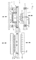
- the device according to the invention Fig. 1 comprises a molding device 1 for producing molded parts with a heating device 50 and a transfer carriage for a cover layer.
- the transfer carriage consists primarily of a clamping frame 60, which holds and carries the two already connected layers or two initially only superimposed layers cover layer 20.
- the cover layer 20 comprises a skin 21 on a foam serving as a carrier 22.
- the clamping frame 60 moves along rails 61 into the heating device 50. It holds the cover layer 20 while it is being heated in the heating device 50 and lies on the temperature control plate 54. Then, the stenter moves along the rails 61 to transport the heated cover layer 20 into the former 1.
- the heating device 50 comprises radiant heaters or an infrared radiator arrangement 52, which is arranged above the plane of the clamping frame 60. It also comprises a tempering plate 54, which is arranged in the plane of the clamping frame 60 during the heating process.
- the tempering plate 54 is for example a metal plate which is tempered by means of liquid in channels 56 such that the carrier 22 reaches the desired temperature.
- the infrared radiator arrangement 52 and / or the Tempering 54 are each movable in the vertical direction to the plane of the clamping frame 60 and away from it, as indicated by double arrows. For this serve in principle known, in Fig. 1 not shown devices such as hydraulic or pneumatic cylinders.
- the skin 21 of the cover layer 20 is heated in the heating device 50 so strongly that it becomes doughy or even molten or even molten.
- the degree of viscosity is selected as a function of the material in such a way that a surface structure 21 'can be pressed or impressed in a subsequent working step and then fixed by cooling.
- the skin 21 lies either on the foam layer serving as a carrier 22, or a foam mat forms the underside of the skin 21.
- the material used for the foam for example, is a chemically cross-linked polyurethane. Due to the chemical cross-linking, this material has almost thermosetting properties and is able to withstand high temperatures, so that it is even more than 200 ° C resistant.
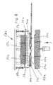
- the molding apparatus 1 comprises a molding tool 2 for forming a front side and a molding tool 3 for forming a back side of a product and in particular the cover layer 20 or a molding 40.
- the molding tool 2 is a female mold, that of a head plate or a carrier 4 is worn while the mold 3 is a patrizeniano lower mold.
- the relative movement between the molds can be achieved by any known mechanism, including hydraulic cylinders, pneumatic cylinders, mechanical drives such as spindle drives, and the like.
- either the mold 2 or the mold 3 may be the upper mold or the lower mold as well as the patrike-like mold or the female mold.
- the mold 2 is preferably the upper mold.
- the molding tool 2 comprises an upper mold half 5 having a surface 5 'which is machined, polished and provided with a surface structure by engraving, etching or the like as described above. This surface structure is provided on one or more selected surface areas or on the entirety of the surface 5 '.
- the mold half 5 is preferably a solid steel mold that is easy to manufacture, machine, polish and engrave or etch by known forming and metalworking techniques. Such a steel mold offers a high inherent strength, a long usable life and allows the provision of a large range of different surface structures in its surface 5 '.
- the upper mold half 5 may be an electroplated zinc mold surface that can be made faster and cheaper (for example, for mold series having a smaller number of parts to be molded) but has a shorter useful life.
- Such a galvanically produced zinc mold may be perforated or made porous by chemical etching or a machining process to provide a continuous suction vacuum.
- the mold 2 includes a vacuum space or chamber 6 having at least one vacuum channel 7 connected to a suitable vacuum source (not shown) adapted to create a slight vacuum, much less than 1 bar below atmospheric pressure, and more particularly less than 0.5 bar below Atmospheric pressure or even less than 0.3 bar (for example 0.05 to 0.3 bar) under atmospheric pressure, and more preferably about 0.1 bar below atmospheric pressure.
- the vacuum channel 7 can also serve as a passive ventilation duct or it can optionally have the mold 2 additionally a vent channel 8.
- a plurality of openings for generating a negative pressure comprises vacuum holes 9 which extend through the upper mold half 5. They communicate with the vacuum chamber 6 and extend through the surface 5 '.
- Each of these vacuum holes 9 in the solid steel mold half 5 consists of a mechanically drilled hole section 9A and a laser drilled hole section 9B.
- the mechanically drilled bore portion 9A can have any suitable diameter, for example 3 to 5 mm, while the laser drilled bore portion 95 has a very fine diameter, for example less than 0.5 mm, or even less than 0.3 mm, and in some cases about 0 , 2 mm.
- Such a combined structure of the vacuum wells 9 efficiently combines the advantages of fast and economical mechanical drilling with the advantages of a small diameter bore made by laser drilling.
- the diameter of the laser drilled bore portion 9B is selected so that the molten skin material is prevented from entering or being sucked into these vacuum wells 9 to prevent the formation of undesirable nodules and spots or other imperfections on the finished surface of the molding.
- the vacuum holes 9 are formed or etched by chemical means with the required small diameter through the mold.
- the numerous vacuum bores 9 are distributed and arranged in a pattern, for example, at intervals of 30 to 40 mm from each other across the entire relevant surface 5 ', to which a vacuum is applied to uniform application of the vacuum and the venting and removal of any trapped To ensure exhaust air.
- the mold half 5 further includes cooling channels 10 through which a tempering liquid such as water or oil can flow to temper the mold half 5 to a constant and uniform temperature suitable for cooling and solidifying the molded part at a suitable rate, for example one Mold temperature in the range of 45 to 60 ° C and especially about 50 ° C.
- a tempering liquid such as water or oil
- the mold 3 comprises a second mold half 11 having a second surface 11 'generally configured to mate with the upper mold half 5 leaving a suitable gap (eg, about 4 mm) therebetween, as described below.
- the mold 3 is provided with an air space or air passage 12 which is connected to an air duct 13 and opens with air holes 14 in different planes or portions of its surface 11 '.
- the line 13 may be with a compressed air source for example, initially 100 ° C hot air or with another pressure medium such as steam, another gas or a liquid at a pressure of 1 to 30 bar, in particular from 6 to 30 bar and especially from 5 up to 20 bar, are connected.
- the air holes 14 may be formed of mechanically drilled holes of suitable diameter and are distributed over the surface 11 'of the lower mold or the lower mold half 11, to ensure a uniform distribution of the compressed air or the other pressure medium in the molding process.
- the air holes 14 may have mechanically drilled portions and laser drilled portions, as is the case with the vacuum holes 9 in the upper mold half 5 and upper mold 5, respectively.
- Such a configuration allows the application of either a pressure medium or a vacuum via the air duct 13 and then through the air holes 14.
- the apparatus can be operated in a first molding stage with vacuum applied through the upper mold half 5 and with pressure passing through the lower mold half 11 is applied to form two cover layers located on opposite sides of a substrate and laminated together, wherein the skin of the cover layers on both opposite sides of the molded part according to the invention are provided with a surface structure.
- the surface 11 is similar to the surface 5 'provided with a surface structure.
- the mold half 5 and the mold half 11 is provided with cooling channels 15 through which a bath liquid can be circulated to keep the mold half 11 at a gleichfflef3igei and constant temperature, which is for example in the range of 45 ° to 60 ° C.
- the apparatus 1 further comprises a circumferentially circumferential sealing frame 16 which serves to provide an airtight high pressure seal between the lower mold half 11 and the upper mold half 5 along its circumference to hold a pressurized pressure medium in the mold gap, as described below becomes.
- the sealing frame 16 is preferably resiliently mounted on the mold 3 or on the lower mold 3, so that it with this in the direction of the Forming tool 2 moves until a sealing member 17 presses against the cover layer and seals (as will be described below).
- an elastic spring means 18 such as a spring, a pneumatic cylinder or the like provides a predetermined force to firmly hold the sealing member 17 against the upper mold half 5 with the cover layer 20 sandwiched therebetween.
- the sealing frame 16 may be configured to receive or cooperate with the clamping frame 60 to achieve the required airtight seal.
- Fig. 1 shows an initial stage in operating the device according to the invention.
- a cover layer 20 having a skin 21 and a support 22 was heated in the heater 50 (as indicated by dashed lines) and then transported by means of the tenter 60 along a flat horizontal plane, along the rails 61, between the mold half 5 and the mold half 11 to be positioned.
- the cover layer 20 is supported and held at its peripheral edges by the tenter 60 or, alternatively, any other known means.
- the heated cover layer 20 can be easily placed on the second mold half 11 even with smaller formats.
- the skin 21 is a thermoplastic film
- the backing 22 is a closed-cell or substantially closed-cell polymeric foam which is preferably air-impermeable over its thickness.
- the cover layer 20 is a conventional known back-foamed thermoplastic polyolefin (TPO) film.
- the skin 21 is preferably a polypropylene film or a polyethylene film, but may alternatively be a film of polyvinyl chloride.
- the carrier 22 may be made of the same polymeric material as the skin 21 (e.g. Polypropylene) but in a foamed state, or it may be a different polymer material (eg, polyurethane), which preferably has a higher melting point than that of skin 21 (or no actual melting temperature due to crosslinking).
- a preferred general combination is a meltable thermoplastic skin 21 on a non-melting, thermoset, or higher temperature melting thermoplastic carrier 22.
- the cover layer 20 was preheated by means of a heater, for example by means of the illustrated infrared radiator arrangement 52, to heat the skin 21 (for example to about 200 ° C) while the support 22 rests on the temperature control plate 54 so that the support is kept relatively cold becomes (for example, below about 160 ° C or specifically about 140 ° C or lower) so that it does not melt.
- the cover layer 20 has been heated so that the skin 21 reaches at least its melting temperature (and with sufficient residual heat so that it remains molten until it is formed in the subsequent step) while the backing 22 reaches a temperature at which it is moldable , but the temperature is below the melting temperature of the carrier 22.
- the skin 21 has been substantially or completely melted into a viscous state so that it can uniformly adhere to and be carried by the carrier 22, which maintains its firm, foamable state.
- the carrier 22 is not softened to a state in which it is unable to provide tension and support for the molten material of the skin 21.
- the cover layer 20 is preferably oriented as shown with the skin 21 disposed on the top of the bottomed support 22. *** " Therefore, the molten skin can not drip or drain from the carrier 22.
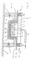
- the mold half 11 After the heated cover layer 20 as in Fig. 1 is arranged between the mold half 5 and the mold half 11, the mold half 11 is moved upward and / or the mold half 5 is moved downward, so that the mold half 11 and its surface 11 ', the cover layer 20 relative to the surface 5' of the mold half 5 in deformed a shaped contour, as it essentially Fig. 2 shows.
- the mold half 11 engages the somewhat cooler, unmelted carrier 22 and performs a deep drawing step in a first operation. In this case, the molten skin 21 may already be pressed against the structured surface 5 '. Further, the sealing frame 16 is pressed against the mold half 5 and forms an airtight seal along the circumference of the cover layer 20.
- the air passively from the space between the cover layer 20 and the surface 5 'through the vacuum holes 9 and through the vacuum channel. 7 or escape the vent channel 8. It is not necessary, but optionally possible, to apply a vacuum through the vacuum channel 7 at this stage. It is preferred that no vacuum be generated at this stage to reduce the energy expenditure in view of the rather large volume of air.
- the mold half 11 has moved upwards in an end position relative to the mold half 5, wherein a defined mold gap 23 between the surface 5 'and the surface 11' remains.
- This mold gap 23 is secured by the circumferential sealing frame 16 or another element which acts as a stop for the movement of the mold half 11 relative to the mold half 5.
- the mold gap 23 has a dual function and dimensions such that it is capable of receiving the cover layer 20 and forming an air gap 24 between the two surfaces 5 'and 11'.
- the air gap 24 is preferably sized (for example, 4 mm) to correspond to the thickness of the substrate 30, which is formed in another step, as will be described later.
- the sealing elements 17 of the peripheral sealing frame 16 had been applied to the edge of the carrier 22 to form an effective seal against high pressure, wherein the sealing elements press the cover layer 20 against an edge of the upper mold half 5.
- the elastically resilient suspension device 18 holds like a spring, the predetermined sealing pressure or the sealing force upright.
- a pressure medium preferably compressed air, is introduced through the air duct 13, the air duct 12 and the air holes 14 into the air gap 24 at a significant pressure (for example 6 to 30 bar).
- a slight vacuum or vacuum may be applied through the vacuum channel 7 to remove residual air bubbles while applying a negative pressure through the vacuum holes 9 on the skin 21.
- the pressure medium presses uniformly against the carrier 22, and the final shaping of the cover layer 20 against the surface 5 'is achieved by means of a purely pneumatic blow molding, preferably without direct mechanical mold contact between the surface 11 and the cover layer 20 in this method step.
- the result is a very uniform and contour-adapted shaping of the cover layer against the surface 5 ', which compensates for any tolerances or deviations or the like between the two forms.
- the carrier 22 is not (or substantially not) permeable to air, it acts as a buffer or intermediate layer and uniformly distributes the molding pressure to the skin 21. Thereby, the molten skin is uniformly pressed and formed against the structured surface 5 '.
- the negative pressure that can be applied through the vacuum holes 9 ensures that no air pockets trapped between the skin 21 and the surface 5 'remain the skin 21 is held firmly in a predetermined, aligned position relative to the surface 5 '.
- the cover layer 20 with the substantially molten skin 21 in a viscous-liquid state and at a temperature above its melting point in the device 1 was arranged.
- the cover layer 20 is deformed against the structured surface 5 'by pressure, there will be an exact inverse or inverse pattern of the structure in the molten skin 21. Since the molten skin 21 is in contact with the mold half 5 (which is replaced by the When the cooling channels 10 are cooled to a temperature of about 50 ° C., the molten material of the skin 21 begins to cool and then solidify when it has cooled below the melting temperature.
- the resulting contour and the surface structure of the skin 21 are "frozen” or fixed.
- the preheated carrier 22 is cooled by the tempered mold half 11, so that it becomes stiffer and maintains the shaped contour.
- the supply of pressure medium through the air duct 13 is interrupted, while the application of negative pressure through the vacuum channel 7 and the vacuum holes 9 is preferably continued to keep the molded cover layer 20 in a fixed position in the mold half 5.
- the cooling and solidification of the cover layer 20 continues.
- the device 1 is opened, for which purpose the mold half 11 is moved downward and / or the mold half 5 upwards.
- the finished, molded and patterned cover layer 20 and may later be applied to a desired substrate or part in a separate process as cover skin.
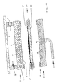
- the cover layer 20 may be further held by vacuum on the mold half 5, and a substrate 30 may be molded directly onto the back side of the preformed cover layer 20 in the same device 1.
- the substrate material 30 between the mold half 11 and the mold half 5, namely between the mold half 11 and the carrier 22 of the cover layer 20 is inserted.
- This substrate material 30 is preferably a preheated layer of a composite material of polyolefin fibers, for example polypropylene fibers and natural fibers or glass fibers or polyester fibers or the like, or a polyurethane foam preheated by known means and carried into the device by known means or is placed in it.
- the mold apparatus 1 is closed, with the mold 3 being moved upwards for one back and / or the mold 2, so that the mold half 11 presses and molds the substrate 30 against the back side of the carrier 22 of the previously formed cover layer 20.
- the molding can be performed completely mechanically, that is, without requiring a pressure medium supplied through the air duct 13, but alternatively, it is advantageous to again introduce a pressure medium through the air duct 13 to apply a uniform molding pressure to the substrate 30, which results in an adjustment or compensation for any deviations or tolerances in the shape contours.
- the preheated and at least partially melted polyolefin fibers of the substrate 30 undergo fusion bonding with the still hot or still hot backing 22 of the cover layer 20 such that the substrate 30 is integral with the cover layer 20 is connected without any intermediate adhesive or the like is required.
- the substrate 30 has been mechanically formed and deformed into the required three-dimensionally contoured configuration, while the substrate material 30 now occupies the portion of the mold gap 23 previously occupied by the air gap 24 in the forming step Fig. 2 was.
- the entire molding process can be carried out with its sequence of steps for forming and applying a surface structure to the cover layer 20 and then molding and laminating the substrate 30 onto the cover layer 20 with a single set of molding tools in a single device 1 two consecutive molding stages, without requiring any reorientation or repositioning of the molds or other equipment and without having to move the molded part to another apparatus for any required process step.
- Fig. 4 schematically the enlarged result of according to Fig. 2 carried out first stage of molding. Namely, both the surface structure of the surface 5 'and the resulting surface structure 21' of the skin 21 of the cover layer 20 are enlarged to clearly illustrate that the resulting surface structure 21 'of the skin 21 is the exact undistorted negative image or inverse surface texture is, which was embossed or pressed into the surface 5 'of the mold half 5.
- Fig. 5 an enlarged schematic detail of the result from the implementation of the second shaping stage according to Fig. 3 .
- the cover layer 20 retains its surface structure 21 'and contour while a substrate material 30 has been formed and laminated on its back surface.
- the substrate material 30 is formed into the required three-dimensionally contoured shape and molded while being laminated and adhered to the support 22 of the cover layer 20.
- the pressure medium itself is a foaming polymer resin, which is introduced in liquid form into the mold gap, for example by injection through corresponding injection channels in the mold stage according to Fig. 2 , As a result, this combines the steps of Fig. 2 and Fig. 3 to a single stage.
- foaming polymer resin begins to foam and expands, it produces a corresponding pressure and it acts as a pressure medium, the cover layer 20 against the surface 5 'in the molding stage according to Fig. 2 pushes as described above. Then, when the foaming polymer resin cools and hardens or cures, being in contact with the tempered mold half 11, it directly forms the substrate 30 as in FIG Fig. 3 shown. Accordingly, backfoaming allows the entire molding process to be performed with a single cycle of opening and firing.
- the substrate 30 and the capping layer 20 are further cooled and somewhat solidified in the step shown in FIG Fig. 3 , which is a consequence of the contact with the mold half 5 and the mold half 11, which are tempered by means of cooling.
- the finished molding 40 shown schematically in FIG Fig. 5 is removed from the mold after the vacuum deposition has been interrupted by the vacuum channel 7.
- the formed cover layer 20 could be used without the substrate lamination according to FIG Fig. 3 be used. In other words, after completing the procedure according to Fig. 2 considered complete.
- the formed and patterned overcoat could be conventionally combined with any conventional substrate or used "as is” in appropriate applications.
- another covering layer may be formed on the opposite surface of the substrate 30, which additional covering layer may also be provided with a surface structure in its skin.
- the cover layer would be preheated in the same way as the cover layer 20, so that its skin is brought to a temperature above the melting temperature while its support has a temperature below the melting point.
- the preheated additional covering layer is introduced into the open mold between the substrate and the lower mold or lower mold half 11, whose surface 11 'has also been provided with a surface structure. Then the mold is closed with a sufficiently large mold gap opening, so that the space for the additional cover layer is present.
- Compressed air is supplied to the vacuum holes 9 while a vacuum is applied through the air holes 14 to substantially conform to the initial molding and the surface structuring method of FIG Fig. 2 perform, but the functions of the upper mold half 5 and the other mold half 11 are interchanged.
- blow molding can not be achieved to the same extent as in the first stage, but the molded surface structure is formed.
- a finished molding 40 can be made having structured surfaces 21 'of the respective skin 21 on opposite sides.
- a modified form of the heater 50 is in the Fig. 6-8 shown. Basically, the same parts have the same reference numerals and in addition the letter index a as in the heater 50 according to Fig. 1 on.
- the heating device 50a is used for heating a cover layer 20a, which consists of a subsequently designated as skin 21 a decorative layer and a second, serving as a support for the highly heated skin 21 a supporting layer.
- Characteristic of the heating device 50a in comparison with the other heating device 50 is an additionally provided protective hood 70a, which ensures that the two-layer covering layer 20a is in a closed chamber 71a when heated. The heating zone is thus encapsulated during the heating process.
- different heating elements are provided with different objectives.
- these are radiant heaters and, in particular, infrared radiators 53a on a ceiling element 55a which terminates the chamber 71a on the one hand and a contact heater with a contact surface in the form of a tempering plate 54a on the other hand.
- the temperature control plate 54a contacts the cover layer 20a from below.
- the protective hood 70a comprises side walls 57a, which can be arranged on all sides.
- intermediate pieces 58a are provided which bridge the free space between the side walls 57a and the ceiling element 55a.
- the intermediate pieces 58a are rigidly connected to the ceiling member 55a of the heater 50a.
- the side walls 57a are movable up and down relative to the intermediate pieces 58a. This makes it possible to open the chamber 71 a and close. To a two-ply or consisting of two individual layers cover layer 20a in the chamber 71 a, it must be opened. In order to heat the skin 21 a to the required extent and uniformly or to heat in a doughy or almost liquid state, the side walls 57 a of the protective cover 70 a are lowered until the chamber 71 a is closed. To remove the cover layer 20a by means of the clamping frame 60a, the chamber 71a is then opened again, as in Fig. 6 is shown.
- drive means 59a are provided, which may be pneumatic or hydraulic drives.
- the protective hood 70a or closed during the heating chamber 71 a are used to produce a uniform temperature distribution, but also expediently provided temperature sensor 62a in the interior of the chamber 71 a. At least two temperature sensors 62a are arranged between the infrared radiators 53a and with the aid of a control, which is of no interest here, it is possible, if appropriate, to throttle various radiant heaters or to increase their effect.
- the cover layer 20a consists of two layers 21a and 22a.
- the melting points of the materials of these two layers 21 a and 22 a are different.
- the one serving as a decorative layer 21 a position has a lower melting point compared to the other, serving as a carrier 22 a position.
- the tempering plate 54a is provided, and ensures that the sheet serving as the carrier 22a is kept at a sufficiently low temperature during the heating operation so as to maintain sufficient stability and strength to carry and transport the other sheet 21a despite its heating and softening.
- the degree of softening of serving as skin or decorative layer layer 21 a may be different according to the requirements. There must be a thermoplastic connection with the carrier 22a and a surface structuring or the like by a printing and embossing process must be possible in principle. Both serving as a decorative layer layer 21 a and serving as a support layer 22 a may be plastic films.
- the material used for the support layer 22a is in particular a chemically crosslinked, closed-cell plastic foam. Either the softening temperature thereof is substantially higher than that of the highly heated decorative layer 21a, or the temperature control for the support layer 22a in the heater 50a is selected such that the support layer 22a maintains sufficient stability and strength to serve as a support for the softened, doughy, viscous or to serve molten skin 21a.
- the temperature control in the heating device 50, 50a may therefore be such that the one layer 21, 21a to a temperature of 200 ° C (about 200 ° C) and the other layer 22, 22a to a temperature of 100 ° C (about 100 ° C) is heated.
- the tempering plate 54, 54a then preferably has a temperature of about 80 ° C to 90 ° C.
- a deep drawing step and then only pressure with the aid of a flow medium are used.
- a vacuum or underpressure is applied in the device 1 only when the skin 21, 21a has hardened sufficiently to prevent the skin from slipping out of the contour, and it is preferred that the backing is pressed against a substrate of, for example, only in a further step 200 ° C hot polypropylene natural fiber mixture.
- the foam has not only a function as a carrier material, but also as a bridge in the negative pressure in the Device 1. It helps to prevent the skin from being sucked into the laser drilled bore sections 98.
- multi-layer molded parts 40 and in particular interior trim parts for motor vehicles can be produced, wherein first a semi-finished product / intermediate product by deep drawing and back-pressing with a flow medium, d. H. in particular with compressed air in a mold gap 23 between two mold halves 5, 11 can be prepared and that then a substrate 30 is applied to the semifinished product that the mold gap 23 is filled with the substrate material, so that the semifinished product for the production of the final product mold halves 5, 11 does not have to be removed.
Applications Claiming Priority (2)
| Application Number | Priority Date | Filing Date | Title |
|---|---|---|---|
| US09/929,693 US6749794B2 (en) | 2001-08-13 | 2001-08-13 | Method and apparatus for molding components with molded-in surface texture |
| EP02017847.1A EP1284182B1 (fr) | 2001-08-13 | 2002-08-08 | Procédé pour thermoformer des pièces avec des structures à la surface |
Related Parent Applications (2)
| Application Number | Title | Priority Date | Filing Date |
|---|---|---|---|
| EP02017847.1A Division EP1284182B1 (fr) | 2001-08-13 | 2002-08-08 | Procédé pour thermoformer des pièces avec des structures à la surface |
| EP02017847.1A Division-Into EP1284182B1 (fr) | 2001-08-13 | 2002-08-08 | Procédé pour thermoformer des pièces avec des structures à la surface |
Publications (1)
| Publication Number | Publication Date |
|---|---|
| EP1974893A2 true EP1974893A2 (fr) | 2008-10-01 |
Family
ID=25458294
Family Applications (2)
| Application Number | Title | Priority Date | Filing Date |
|---|---|---|---|
| EP02017847.1A Expired - Lifetime EP1284182B1 (fr) | 2001-08-13 | 2002-08-08 | Procédé pour thermoformer des pièces avec des structures à la surface |
| EP08012435A Withdrawn EP1974893A2 (fr) | 2001-08-13 | 2002-08-08 | Apparareil pour thermoformer des pièces avec imprimees à la surface |
Family Applications Before (1)
| Application Number | Title | Priority Date | Filing Date |
|---|---|---|---|
| EP02017847.1A Expired - Lifetime EP1284182B1 (fr) | 2001-08-13 | 2002-08-08 | Procédé pour thermoformer des pièces avec des structures à la surface |
Country Status (5)
| Country | Link |
|---|---|
| US (1) | US6749794B2 (fr) |
| EP (2) | EP1284182B1 (fr) |
| JP (1) | JP4371638B2 (fr) |
| KR (1) | KR20030015155A (fr) |
| ES (1) | ES2526800T3 (fr) |
Cited By (2)
| Publication number | Priority date | Publication date | Assignee | Title |
|---|---|---|---|---|
| CN107150426A (zh) * | 2017-06-30 | 2017-09-12 | 中山市程博工业产品设计有限公司 | 一种使用方便的汽车模具 |
| DE102019204821A1 (de) * | 2019-04-04 | 2020-10-08 | Multivac Sepp Haggenmüller Se & Co. Kg | Formeinsatz für eine Tiefziehverpackungsmaschine und Herstellungsverfahren |
Families Citing this family (111)
| Publication number | Priority date | Publication date | Assignee | Title |
|---|---|---|---|---|
| US6652273B2 (en) * | 2002-01-14 | 2003-11-25 | The Procter & Gamble Company | Apparatus and method for controlling the temperature of manufacturing equipment |
| EP1371476A1 (fr) * | 2002-02-15 | 2003-12-17 | R+S Technik GmbH | Appareil pour la fabrication de habillage intérieur pour véhicules |
| KR100499866B1 (ko) * | 2002-12-18 | 2005-07-07 | 한국과학기술원 | 요철모양의 금형을 이용한 mcp 제작 방법 및 장치 |
| DE10301712B4 (de) * | 2003-01-13 | 2004-11-04 | Sai Automotive Sal Gmbh | Verfahren zum Herstellen von hinterspritzten Kunststoffformteilen |
| US20040209123A1 (en) * | 2003-04-17 | 2004-10-21 | Bajorek Christopher H. | Method of fabricating a discrete track recording disk using a bilayer resist for metal lift-off |
| DE10328046A1 (de) * | 2003-06-23 | 2005-01-13 | Arvinmeritor Gmbh | Verfahren zum Herstellen eines Kunststoffverbundbauteils, insbesondere eines Karosserieanbauteils |
| DE10333161A1 (de) † | 2003-07-22 | 2005-02-24 | Findlay Industries Deutschland Gmbh | Innenausstattungskomponenten von Kraftfahrzeugen mit einem definierten Oberflächenprofil |
| US7922956B1 (en) * | 2003-11-05 | 2011-04-12 | Leon Plastics, Inc. | Vehicular trim component and cover with simulated stitch and/or seam thereon |
| US20050151282A1 (en) * | 2004-01-13 | 2005-07-14 | Harper Bruce M. | Workpiece handler and alignment assembly |
| US7329114B2 (en) * | 2004-01-20 | 2008-02-12 | Komag, Inc. | Isothermal imprint embossing system |
| US7686606B2 (en) * | 2004-01-20 | 2010-03-30 | Wd Media, Inc. | Imprint embossing alignment system |
| US20050183897A1 (en) * | 2004-02-24 | 2005-08-25 | Lear Corporation | Two-shot co-injected automotive interior trim assembly and method |
| NO323512B1 (no) * | 2004-04-07 | 2007-06-04 | Crescendo As | Stopeform for framstilling av en hjelmfôring. |
| US20060062970A1 (en) * | 2004-04-19 | 2006-03-23 | Martin James N | Embossed headliner and method of making same |
| US20080169678A1 (en) * | 2004-04-30 | 2008-07-17 | Kyoraku Co., Ltd. | Interior Finishing Panel for Vehicle and Method of Manufacturing the Same |
| US7699595B2 (en) * | 2004-07-19 | 2010-04-20 | R + S Technik Gmbh | Method and apparatus for molding a laminated trim component without use of slip frame |
| US20060027036A1 (en) * | 2004-08-05 | 2006-02-09 | Biggs Todd L | Methods and apparatuses for imprinting substrates |
| US7156437B2 (en) * | 2004-10-19 | 2007-01-02 | Lear Corporation | Automotive trim part with applique and method of making same |
| US7458631B2 (en) * | 2004-10-19 | 2008-12-02 | International Automotive Components Group North America, Inc. | Automotive armrest with soft feel and method of making the same |
| US20060082175A1 (en) * | 2004-10-19 | 2006-04-20 | Cowelchuk Glenn A | Automotive trim part with multi-feel cover and method of making the same |
| US20060082179A1 (en) * | 2004-10-19 | 2006-04-20 | Depue Todd L | Automotive trim assembly having impact countermeasures and method of making the same |
| US7478854B2 (en) * | 2004-10-19 | 2009-01-20 | International Automotive Components Group North America, Inc. | Automotive handle with soft feel and method of making the same |
| US20060082109A1 (en) * | 2004-10-20 | 2006-04-20 | Hier Michael J | Method of making an automotive trim assembly having an integrated airbag door |
| US7458604B2 (en) * | 2004-10-20 | 2008-12-02 | International Automotive Components Group North America, Inc. | Automotive trim assembly having an integrated airbag door |
| US20060099395A1 (en) * | 2004-11-09 | 2006-05-11 | Cowelchuk Glenn A | Automotive interior trim assembly and method |
| US20060097544A1 (en) * | 2004-11-09 | 2006-05-11 | Cowelchuk Glenn A | Automotive interior trim assembly and method |
| US7108312B2 (en) * | 2004-11-09 | 2006-09-19 | Lear Corporation | Vehicle door trim bolster with multi-feel cover and method of making the same |
| US7192074B2 (en) * | 2004-11-10 | 2007-03-20 | Lear Corporation | Automotive compartment having an integrated spring mechanism and method of making the same |
| US7332207B2 (en) * | 2004-12-15 | 2008-02-19 | Visteon Global Technologies, Inc. | Component for a vehicle interior and a method of assembly |
| US20060151097A1 (en) * | 2005-01-13 | 2006-07-13 | Bennett Norman H | Method of making a non-carpeted floor covering |
| FR2880838B1 (fr) * | 2005-01-19 | 2009-03-13 | Visteon Global Tech Inc | Procede de fabrication d'un panneau composite avec une peau decorative et panneau correspondant |
| EP1704979A1 (fr) * | 2005-03-22 | 2006-09-27 | ArvinMeritor GmbH | Moule de thermoformage ou de moussage in situ de feuilles et procédé de fabrication d'un element composite |
| JP2007069355A (ja) * | 2005-09-02 | 2007-03-22 | Toyota Motor Corp | 成形金型 |
| US20070134485A1 (en) * | 2005-12-08 | 2007-06-14 | Collins Daniel J | Blow molded articles having capped or inserted thermoplastic vulcanizate foam surfaces |
| US20070202327A1 (en) * | 2005-12-19 | 2007-08-30 | Alberto Baban | Synthetic cork with a natural cork appearance and method of making it |
| AT503268B1 (de) * | 2006-02-20 | 2008-07-15 | Greiner Perfoam Gmbh | Verfahren zur herstellung eines mehrlagigen bauteils |
| DE102006022263B4 (de) * | 2006-05-11 | 2008-04-03 | Uhlmann Pac-Systeme Gmbh & Co. Kg | Heizstation |
| KR100783617B1 (ko) * | 2006-05-18 | 2007-12-10 | 덕양산업 주식회사 | 미세발포 시트를 적용한 다층구조의 인스트루먼트 판넬 및 그 제조방법 |
| DE102006026063B4 (de) * | 2006-06-03 | 2020-02-27 | Kraussmaffei Technologies Gmbh | Verfahren zur Herstellung von beschichteten Verbund-Kunststoffformteilen und Spritzgießmaschine hierfür |
| US8794951B2 (en) * | 2006-12-01 | 2014-08-05 | Tanazawa Hallosha Co., Ltd. | Mold for resin molding, method for manufacturing mold for resin molding, and resin molded product |
| DE102007009384B4 (de) * | 2007-02-20 | 2020-11-26 | Faurecia Innenraum Systeme Gmbh | Verfahren zum Hinterspritzen einer Folie |
| KR100815497B1 (ko) | 2007-04-18 | 2008-03-20 | 한일이화주식회사 | 차량용 트렁크모듈 부품의 제조장치 및 방법 |
| DE102007046472B4 (de) * | 2007-09-28 | 2013-12-24 | Bayer Materialscience Aktiengesellschaft | Verfahren zur Herstellung eines tiefgezogenen Folienteils aus Polycarbonat oder aus Polymethylmethacrylat |
| WO2009070757A1 (fr) * | 2007-11-26 | 2009-06-04 | International Automotive Components Group North America, Inc. | Application de faux bois en 3d |
| JP5025549B2 (ja) | 2008-03-31 | 2012-09-12 | キョーラク株式会社 | 発泡ブロー成形品およびその製造方法 |
| US8012290B2 (en) * | 2008-06-30 | 2011-09-06 | Herbert Olbrich Gmbh & Co. Kg | Method and apparatus for producing a three-dimensionally molded, laminated article with transfer-printed surface decoration |
| CN101618597A (zh) * | 2008-07-04 | 2010-01-06 | 深圳富泰宏精密工业有限公司 | 吸塑模具及其抽气孔打孔装置 |
| ATE494129T1 (de) * | 2008-10-24 | 2011-01-15 | Faurecia Innenraum Sys Gmbh | Verfahren zum herstellen eine formhaut |
| JP5253103B2 (ja) * | 2008-11-17 | 2013-07-31 | 日産自動車株式会社 | 車両用内装部品 |
| DE102009031453A1 (de) * | 2009-07-02 | 2011-01-05 | Werner Beuerlein | Gussform mit Entlüfter |
| WO2011030938A1 (fr) * | 2009-09-10 | 2011-03-17 | (주)엘지하우시스 | Procédé de moulage à l'aide de pression d'eau ou de pression de vapeur et dispositif de moulage |
| ES2388554T3 (es) * | 2009-10-14 | 2012-10-16 | Abb Technology Ag | Actuador magnético biestable para un disyuntor de media tensión |
| US8496466B1 (en) | 2009-11-06 | 2013-07-30 | WD Media, LLC | Press system with interleaved embossing foil holders for nano-imprinting of recording media |
| US9330685B1 (en) | 2009-11-06 | 2016-05-03 | WD Media, LLC | Press system for nano-imprinting of recording media with a two step pressing method |
| US8402638B1 (en) | 2009-11-06 | 2013-03-26 | Wd Media, Inc. | Press system with embossing foil free to expand for nano-imprinting of recording media |
| US20110204611A1 (en) * | 2010-02-18 | 2011-08-25 | Daimler Trucks North America Llc | Fiber reinforced polymer frame rail |
| JP5619449B2 (ja) * | 2010-03-26 | 2014-11-05 | 株式会社浅野研究所 | 差圧成形装置、及び、差圧成形シート製造方法 |
| JP5349403B2 (ja) * | 2010-05-17 | 2013-11-20 | テクノポリマー株式会社 | 光照射成形装置及び方法 |
| US20120104641A1 (en) | 2010-11-02 | 2012-05-03 | Honeywell International Inc. | Apparatus for pitch densification |
| US20120104659A1 (en) * | 2010-11-02 | 2012-05-03 | Honeywell International Inc. | Apparatus for pitch densification |
| CA2854615C (fr) * | 2010-11-05 | 2017-01-24 | Lightweight Labs, Llc | Systeme et procede de traitement et de consolidation thermiques |
| US20120153528A1 (en) | 2010-12-17 | 2012-06-21 | Honeywell International Inc. | Apparatus for carbon fiber processing and pitch densification |
| KR101268789B1 (ko) * | 2010-12-29 | 2013-05-29 | (주)엘지하우시스 | 진공 금형 및 이를 이용한 진공 성형방법 |
| FR2978948B1 (fr) * | 2011-08-09 | 2015-05-15 | Faurecia Interieur Ind | Procede de realisation d'un element de garnissage comprenant une zone de decor d'aspect particulier |
| CN104023942A (zh) * | 2012-01-11 | 2014-09-03 | Scivax股份有限公司 | 成型方法和成型装置 |
| DE102012006034A1 (de) * | 2012-03-27 | 2013-10-02 | Mbb Fertigungstechnik Gmbh | Verfahren zur Herstellung eines im Wesentlichen schalenförmigen, faserverstärkten Kunststoffteils |
| DE102012222000A1 (de) * | 2012-11-30 | 2014-06-05 | Hp Pelzer Holding Gmbh | Herstellung wenigstens zweilagiger Bauteile |
| JP6364684B2 (ja) * | 2012-12-06 | 2018-08-01 | Scivax株式会社 | ローラ式加圧装置、インプリント装置、ローラ式加圧方法 |
| EP2956498B1 (fr) * | 2013-02-12 | 2023-10-11 | Fraunhofer-Gesellschaft zur Förderung der angewandten Forschung e.V. | Feuilles de séparation siliconées ayant une excellente propriété à l'emboutissage sous vide |
| CN105209233A (zh) * | 2013-03-15 | 2015-12-30 | 赫尔曼米勒有限公司 | 具有纹理化表面的颗粒泡沫部件 |
| US9821509B2 (en) * | 2013-07-29 | 2017-11-21 | Faurecia Innenraum Systeme Gmbh | Method and device for producing an interior covering part |
| TW201507814A (zh) * | 2013-08-16 | 2015-03-01 | San Fang Chemical Industry Co | 製造硏磨墊及硏磨裝置之方法 |
| US11135760B2 (en) | 2013-08-20 | 2021-10-05 | Sabic Global Technologies B.V. | Process for forming articles from extruded polymer sheet |
| WO2015065413A1 (fr) * | 2013-10-31 | 2015-05-07 | Hewlett-Packard Development Company, L.P. | Film texturé sur un substrat |
| DE102014202357A1 (de) | 2014-02-10 | 2015-08-13 | Bayerische Motoren Werke Aktiengesellschaft | Verfahren zur Herstellung eines Verbundbauteils und Verbundbauteil |
| WO2015186736A1 (fr) * | 2014-06-03 | 2015-12-10 | Scivax株式会社 | Dispositif de mise sous pression du type à rouleaux, dispositif d'impression, et procédé de mise sous pression du type à rouleaux |
| CN104309104A (zh) * | 2014-08-26 | 2015-01-28 | 金兴汽车内饰股份有限公司 | 汽车仪表板表皮阴模真空成型工艺 |
| DE102014219396A1 (de) * | 2014-09-25 | 2016-03-31 | Adidas Ag | Herstellungsverfahren für eine äußere Schicht für ein Paneel eines Balls |
| CN104441587B (zh) * | 2014-12-05 | 2017-02-01 | 瑞安市博诚机械有限公司 | 一种塑料杯盖热成型机 |
| US9944526B2 (en) | 2015-05-13 | 2018-04-17 | Honeywell International Inc. | Carbon fiber preforms |
| US10302163B2 (en) | 2015-05-13 | 2019-05-28 | Honeywell International Inc. | Carbon-carbon composite component with antioxidant coating |
| US10131113B2 (en) | 2015-05-13 | 2018-11-20 | Honeywell International Inc. | Multilayered carbon-carbon composite |
| US10076856B2 (en) | 2015-06-15 | 2018-09-18 | International Automotive Components Group North America, Inc. | Manufacture of an article having a decorative cover sheet overlying a substrate |
| US10035305B2 (en) | 2015-06-30 | 2018-07-31 | Honeywell International Inc. | Method of making carbon fiber preforms |
| US10737423B2 (en) * | 2015-08-28 | 2020-08-11 | The Boeing Company | Systems and methods for sealant injection molding |
| US10022890B2 (en) | 2015-09-15 | 2018-07-17 | Honeywell International Inc. | In situ carbonization of a resin to form a carbon-carbon composite |
| KR101771653B1 (ko) | 2015-11-19 | 2017-08-25 | 한국신발피혁연구원 | 솔리드 성형재료의 가변압 발포 성형방법 |
| US10300631B2 (en) | 2015-11-30 | 2019-05-28 | Honeywell International Inc. | Carbon fiber preforms |
| ES2615331B1 (es) * | 2015-12-03 | 2018-03-13 | Mecánica Y Tecnología Alimentaria, S.L. | Tapa para envases de producto dosificado en caliente y dispositivo para su fabricación |
| US10828822B2 (en) | 2016-08-04 | 2020-11-10 | The Boeing Company | Method for fabricating thermoplastic sandwich structural panel using thermoforming and compression molding |
| US10207434B2 (en) * | 2016-08-04 | 2019-02-19 | The Boeing Company | In-mold apparatus and method for decorative application |
| SE540754C2 (en) | 2016-11-30 | 2018-10-30 | Ikea Supply Ag | Molding of fiber blanks into three-dimensional fiber block |
| KR20180064605A (ko) * | 2016-12-05 | 2018-06-15 | 삼성디스플레이 주식회사 | 레이저 가공용 워크 테이블 및 이의 동작 방법 |
| GB2561334B (en) * | 2017-02-23 | 2022-05-18 | Auxetic Performance Ltd | A method of fabricating a workpiece made of fibres and resin |
| DE102017103943A1 (de) * | 2017-02-24 | 2018-08-30 | Auria Solutions Uk I Ltd. | Verkleidungsteil für ein Kraftfahrzeug, Verfahren und Vorrichtung zu seiner Herstellung |
| DE102017214376A1 (de) * | 2017-08-17 | 2019-02-21 | Bayerische Motoren Werke Aktiengesellschaft | Verdeckanordnung für ein Kraftfahrzeug |
| DE102017118960B4 (de) * | 2017-08-18 | 2019-07-11 | Werkzeugbau Siegfried Hofmann Gmbh | Schäumwerkzeug |
| KR102377731B1 (ko) | 2017-10-12 | 2022-03-23 | 현대자동차주식회사 | 차량용 내장재의 성형장치 및 성형방법 |
| US11351703B2 (en) * | 2018-05-30 | 2022-06-07 | The Boeing Company | Matched compression die apparatus |
| JP7396613B2 (ja) * | 2018-05-31 | 2023-12-12 | 地方独立行政法人東京都立産業技術研究センター | 積層造形装置、三次元形状造形物に対する加工方法、三次元形状造形物及び金型 |
| CA3109221A1 (fr) * | 2018-12-19 | 2020-06-25 | Spartan Mat Llc | Systeme de tapis de traction et son procede de fabrication |
| CN109435109A (zh) * | 2018-12-30 | 2019-03-08 | 大连銮艺精密模塑制造有限公司 | 塑料产品精密修整加工治具 |
| US11518160B2 (en) * | 2019-08-29 | 2022-12-06 | Inteva Products, Llc | Method for non-contact adhesive activation and wrapping of a decorative skin to a part having curved surfaces and a part formed by the method |
| US11040664B2 (en) * | 2019-09-09 | 2021-06-22 | Ford Global Technologies, Llc | Support member for vehicle center console lid |
| CN112372995A (zh) * | 2020-10-26 | 2021-02-19 | 东莞市中鼎塑料制品有限公司 | 一种tpu高低温膜复合布的加工方法 |
| IT202000027227A1 (it) * | 2020-11-13 | 2022-05-13 | Persico Spa | Processo di stampaggio di un prodotto composito per rivestimenti |
| DE102020134732A1 (de) | 2020-12-22 | 2022-06-23 | Liebherr-Hausgeräte Ochsenhausen GmbH | Thermoformteil |
| CN113400549B (zh) * | 2021-05-30 | 2022-09-16 | 湖北三江航天江河化工科技有限公司 | 一种异形绝热套模压模具及其操作方法 |
| CN114851525A (zh) * | 2022-03-28 | 2022-08-05 | 南昌航空大学 | 一种pmi泡沫真空热吸成型设备及运行方式 |
| FR3135914A1 (fr) * | 2022-05-30 | 2023-12-01 | Faurecia Interieur Industrie | Procédé de texturisation et de thermoformage d’un film d’aspect de pièce d’habillage |
| WO2024018496A1 (fr) * | 2022-07-20 | 2024-01-25 | Persico S.P.A. | Procédé de revêtement d'un substrat préformé |
Family Cites Families (36)
| Publication number | Priority date | Publication date | Assignee | Title |
|---|---|---|---|---|
| US3676537A (en) * | 1965-11-18 | 1972-07-11 | Thomas W Winstead | Continuous method of extruding and thero-forming skin-covered foamed thermoplastic articles |
| US4036675A (en) * | 1974-06-24 | 1977-07-19 | Owens-Illinois, Inc. | Film-lined foam plastic receptacles and laminated materials and methods for making the same |
| US4167595A (en) | 1975-01-08 | 1979-09-11 | Alkor Gesellschaft Mit Beschrankter Haftung Kunststoffverkauf | Method of printing on plastic foil |
| CH626388A5 (fr) | 1976-12-31 | 1981-11-13 | Alkor Gmbh | |
| DE2910234C2 (de) | 1979-03-15 | 1983-05-26 | Alkor GmbH Kunststoffverkauf, 8000 München | Verfahren zur Herstellung eines Formkörpers aus einer Trägerplatte mit einer Dekorschicht |
| EP0016438B1 (fr) | 1979-03-15 | 1984-06-20 | Alkor Gmbh Kunststoffe | Procédé de fabrication d'un substrat flogué |
| US4751141A (en) | 1981-01-12 | 1988-06-14 | Alkor Gmbh Kunststoffverkauf | Process for the manufacture and use of a polypropylene foil with improved adhesion |
| JPS59232818A (ja) | 1983-06-16 | 1984-12-27 | Tokyo Seat Kk | 圧空金型成形方法 |
| DE3429523A1 (de) | 1984-08-10 | 1986-02-20 | Alkor GmbH Kunststoffe, 8000 München | Schaumlaminatfolie oder -bahn |
| US4921561A (en) * | 1984-10-18 | 1990-05-01 | Honda Giken Kogyo Kabushiki Kaisha | Process for manufacturing embossed articles of synthetic resin |
| EP0213441B1 (fr) | 1985-08-24 | 1991-04-10 | Alkor Gmbh Kunststoffe | Feuille pour meuble |
| US4740417A (en) * | 1986-07-22 | 1988-04-26 | Cone Mills Corporation | Thermoplastic vacuum molding method and article produced thereby |
| DE3723021A1 (de) | 1987-07-11 | 1989-01-19 | Alkor Gmbh | Verfahren und vorrichtung zur herstellung von formteilen oder gegenstaenden |
| DE3714365A1 (de) | 1987-04-30 | 1988-11-17 | Alkor Gmbh | Verfahren und vorrichtung zur herstellung von formteilen oder gegenstaenden aus thermoverformbaren kunststoffolien |
| DE8706204U1 (fr) | 1987-04-30 | 1988-09-01 | Alkor Gmbh Kunststoffe, 8000 Muenchen, De | |
| DE3714367A1 (de) | 1987-04-30 | 1988-11-10 | Alkor Gmbh | Verfahren und vorrichtung zur herstellung von formteilen oder gegenstaenden aus thermoverformbaren kunststoffbahnen |
| DE3714366A1 (de) | 1987-04-30 | 1988-11-10 | Alkor Gmbh | Verfahren zur herstellung von formteilen oder gegenstaenden aus thermoverformbaren kunststoffolien, thermoverformbaren kunststoffhaltigen bahnen oder kunststoffplatten |
| DE8709582U1 (fr) | 1987-07-11 | 1988-11-10 | Alkor Gmbh Kunststoffe, 8000 Muenchen, De | |
| DE3834648A1 (de) | 1988-10-11 | 1990-04-19 | Alkor Gmbh | Verfahren und vorrichtung zur herstellung von formteilen oder gegenstaenden fuer kraftfahrzeuge |
| DE3834608A1 (de) | 1988-10-11 | 1990-04-19 | Alkor Gmbh | Verfahren zur herstellung von formteilen oder gegenstaenden fuer kraftfahrzeuge oder kraftfahrzeuginnenverkleidungen |
| DE3834620A1 (de) | 1988-10-11 | 1990-04-12 | Alkor Gmbh | Verfahren und vorrichtung sowie kunststoffolienbahn zur herstellung von formteilen oder gegenstaenden |
| DE3834607C2 (de) | 1988-10-11 | 1997-12-11 | Alkor Gmbh | Verfahren zur Herstellung von Gegenständen aus thermoverformbaren Kunststoffolien |
| DE4007877C2 (de) | 1990-03-13 | 1998-02-26 | Alkor Gmbh | Verfahren zur Herstellung von geprägten, narbstabilen, thermoverformbaren, vorzugsweise tiefziehfähigen Kunststoffolien |
| DE4007876C2 (de) | 1990-03-13 | 1998-02-12 | Alkor Gmbh | Verfahren zur Herstellung von geprägten, narbstabilen, thermoverformbaren, tiefziehfähigen Kunststoffolien |
| DE4010441C2 (de) | 1990-03-31 | 1994-10-20 | Roeder & Spengler Stanz | Vorrichtung zum Herstellen eines Formteils aus einem verformbaren Werkstück |
| DE4030477C2 (de) | 1990-09-26 | 1999-12-02 | Alkor Gmbh | Verfahren und Vorrichtung zur Herstellung von Formteilen oder Gegenständen |
| US5702810A (en) | 1992-03-10 | 1997-12-30 | Mitsubishi Chemical Corporation | Cushioning composite molded article and a process for production thereof |
| DE59403431D1 (de) | 1993-06-21 | 1997-08-28 | Alkor Gmbh | Tiefziehfähige Folie, Verfahren zu deren Herstellung und Verwendung derselben |
| DE19530757A1 (de) | 1995-08-22 | 1997-02-27 | Alkor Gmbh | Verfahren und Vorrichtung zur Herstellung von zwei- oder mehrfarbigen Schalttafelfolien, Armaturenbrettfolien oder daraus hergestellte Armaturenbretter für Kraftfahrzeuge |
| US5913996A (en) * | 1996-05-28 | 1999-06-22 | Tokyo Seat Co., Ltd. | Method of and apparatus for fabricating interior element for automotive vehicle |
| US5976289A (en) | 1996-12-13 | 1999-11-02 | Toyo Tire & Rubber Co., Ltd. | Method of fabricating instrument panel |
| US5976288A (en) * | 1997-01-10 | 1999-11-02 | Ekendahl; Lars O. | Method of forming a molded, multi-layer structure |
| US6136415A (en) | 1997-05-27 | 2000-10-24 | R + S Technik Gmbh | Vehicle interior trim panel with a soft-touch foam layer, and a method and apparatus for making the same |
| US5863064A (en) * | 1997-08-14 | 1999-01-26 | Textron Autmotive Company Inc. | Skin for automotive air bag cover panel formed by casting different plastic materials |
| US6333094B1 (en) | 1998-09-19 | 2001-12-25 | Alkor Gmbh Kunststoffe | Multilayer thermoformable composite synthetic veneer film for furniture and process for producing same |
| DE19959654A1 (de) | 1999-12-10 | 2001-06-21 | Findlay Ind Deutschland Gmbh | Verfahren zur Herstellung von Innenausstattungskomponenten von Kraftfahrzeugen |
-
2001
- 2001-08-13 US US09/929,693 patent/US6749794B2/en not_active Expired - Lifetime
-
2002
- 2002-08-08 EP EP02017847.1A patent/EP1284182B1/fr not_active Expired - Lifetime
- 2002-08-08 ES ES02017847.1T patent/ES2526800T3/es not_active Expired - Lifetime
- 2002-08-08 EP EP08012435A patent/EP1974893A2/fr not_active Withdrawn
- 2002-08-12 JP JP2002234766A patent/JP4371638B2/ja not_active Expired - Fee Related
- 2002-08-13 KR KR1020020047934A patent/KR20030015155A/ko not_active Application Discontinuation
Cited By (2)
| Publication number | Priority date | Publication date | Assignee | Title |
|---|---|---|---|---|
| CN107150426A (zh) * | 2017-06-30 | 2017-09-12 | 中山市程博工业产品设计有限公司 | 一种使用方便的汽车模具 |
| DE102019204821A1 (de) * | 2019-04-04 | 2020-10-08 | Multivac Sepp Haggenmüller Se & Co. Kg | Formeinsatz für eine Tiefziehverpackungsmaschine und Herstellungsverfahren |
Also Published As
| Publication number | Publication date |
|---|---|
| ES2526800T3 (es) | 2015-01-15 |
| JP4371638B2 (ja) | 2009-11-25 |
| US20030030188A1 (en) | 2003-02-13 |
| EP1284182A3 (fr) | 2003-04-09 |
| US6749794B2 (en) | 2004-06-15 |
| KR20030015155A (ko) | 2003-02-20 |
| EP1284182A2 (fr) | 2003-02-19 |
| JP2003117992A (ja) | 2003-04-23 |
| EP1284182B1 (fr) | 2014-11-26 |
Similar Documents
| Publication | Publication Date | Title |
|---|---|---|
| EP1284182B1 (fr) | Procédé pour thermoformer des pièces avec des structures à la surface | |
| DE69833439T2 (de) | Verfahren und gerät zum herstellen eines geformten gegenstandes | |
| EP0320925B1 (fr) | Procédé de fabrication de pièces moulées en matière plastique à revêtement de surface à estampage décoratif | |
| DE3743881A1 (de) | Geformte verbundplatten | |
| EP1287961A2 (fr) | Elément de revêtement ainsi que procédé et dispositif de fabrication d'un élément de revêtement multicouche | |
| DE10100745A1 (de) | In der Form laminiertes Bauteil und Verfahren zu seiner Herstellung | |
| DE3840542C1 (en) | Process for producing a thin-walled, thermoformed plastic moulding and its use | |
| DE3607647C2 (fr) | ||
| DE102006024263A1 (de) | Kunststoffformteil mit einer dekorativen thermoplastischen Schicht | |
| DE4337697C1 (de) | Verfahren zur Herstellung von formstabilen, kaschierten Formteilen, wie Innenverkleidungen von Kraftfahrzeugen | |
| WO2008113446A1 (fr) | Composant, en particulier élément de garniture interne, et procédé de fabrication dudit composant | |
| WO2010051866A1 (fr) | Procédé et dispositif de fabrication d'une pièce de forme avec surface décorée | |
| EP1235679B1 (fr) | Procede de fabrication de composants d'equipement interieur de vehicules motorises et produit correspondant | |
| DE60025973T2 (de) | Formteil sowie Verfahren zu seiner Herstellung | |
| EP0543085A1 (fr) | Procédé et dispositif pour fabriquer des objets moulés stratifiés | |
| WO2008101739A2 (fr) | Procédé et moule pour produire un élément grainé | |
| DE3844584A1 (de) | Verfahren zur herstellung eines duennwandigen, tiefgezogenen kunststoff-formteils und das erhaltene kunststoff-formteil | |
| DE3108571C2 (de) | Verfahren zum Herstellen eines aus einem Träger und aus einer auf dem Träger angeordneten Deckschicht bestehenden Verbundkörpers sowie Vorrichtung zur Durchführung des Verfahrens | |
| DE102004019293A1 (de) | Verfahren zur Formung von Kunstoffplatten | |
| DE102018212610A1 (de) | Verfahren zur Herstellung eines mehrschichtigen Kunststoffbauteils | |
| EP1843889B1 (fr) | Procede et dispositif pour produire un film plastique thermoforme pourvu d'un grainage de surface | |
| EP1147875A2 (fr) | Procédé pour recouvrir la surface profilée d'une pièce support devant être revêtue avec un matériau décoratif | |
| DE19749106A1 (de) | Verfahren zum Prägen von Materialien | |
| DE4210066C1 (en) | Fabric clip mounting - has injection moulding appts. to shape plastics component and be bonded to fabric at defined location within assembly | |
| DE19843425A1 (de) | Verfahren zur Herstellung einer kontaktlosen Chipkarte |
Legal Events
| Date | Code | Title | Description |
|---|---|---|---|
| PUAI | Public reference made under article 153(3) epc to a published international application that has entered the european phase |
Free format text: ORIGINAL CODE: 0009012 |
|
| AC | Divisional application: reference to earlier application |
Ref document number: 1284182 Country of ref document: EP Kind code of ref document: P |
|
| AK | Designated contracting states |
Kind code of ref document: A2 Designated state(s): AT BE BG CH CY CZ DE DK EE ES FI FR GB GR IE IT LI LU MC NL PT SE SK TR |
|
| AX | Request for extension of the european patent |
Extension state: AL LT LV MK RO SI |
|
| RIN1 | Information on inventor provided before grant (corrected) |
Inventor name: SPENGLER, ERNST MAXIMILIAN |
|
| RAP1 | Party data changed (applicant data changed or rights of an application transferred) |
Owner name: OLBRICH GMBH |
|
| RIC1 | Information provided on ipc code assigned before grant |
Ipc: B29C 59/02 20060101AFI20151215BHEP Ipc: B29C 51/42 20060101ALI20151215BHEP Ipc: B29L 9/00 20060101ALN20151215BHEP Ipc: B29C 51/16 20060101ALN20151215BHEP Ipc: B29C 43/34 20060101ALN20151215BHEP Ipc: B29C 43/36 20060101ALN20151215BHEP Ipc: B29K 105/04 20060101ALN20151215BHEP Ipc: B29L 31/30 20060101ALN20151215BHEP Ipc: B29C 43/00 20060101ALN20151215BHEP Ipc: B29C 51/14 20060101ALI20151215BHEP Ipc: B29C 37/00 20060101ALI20151215BHEP Ipc: B29C 51/30 20060101ALI20151215BHEP |
|
| STAA | Information on the status of an ep patent application or granted ep patent |
Free format text: STATUS: THE APPLICATION HAS BEEN WITHDRAWN |
|
| 18W | Application withdrawn |
Effective date: 20160226 |