EP1974893A2 - Apparatus for forming parts with patterns on its surface - Google Patents
Apparatus for forming parts with patterns on its surface Download PDFInfo
- Publication number
- EP1974893A2 EP1974893A2 EP08012435A EP08012435A EP1974893A2 EP 1974893 A2 EP1974893 A2 EP 1974893A2 EP 08012435 A EP08012435 A EP 08012435A EP 08012435 A EP08012435 A EP 08012435A EP 1974893 A2 EP1974893 A2 EP 1974893A2
- Authority
- EP
- European Patent Office
- Prior art keywords
- mold
- mold half
- vacuum
- layer
- heating
- Prior art date
- Legal status (The legal status is an assumption and is not a legal conclusion. Google has not performed a legal analysis and makes no representation as to the accuracy of the status listed.)
- Withdrawn
Links
Images


Classifications
-
- B—PERFORMING OPERATIONS; TRANSPORTING
- B29—WORKING OF PLASTICS; WORKING OF SUBSTANCES IN A PLASTIC STATE IN GENERAL
- B29C—SHAPING OR JOINING OF PLASTICS; SHAPING OF MATERIAL IN A PLASTIC STATE, NOT OTHERWISE PROVIDED FOR; AFTER-TREATMENT OF THE SHAPED PRODUCTS, e.g. REPAIRING
- B29C59/00—Surface shaping of articles, e.g. embossing; Apparatus therefor
- B29C59/02—Surface shaping of articles, e.g. embossing; Apparatus therefor by mechanical means, e.g. pressing
- B29C59/026—Surface shaping of articles, e.g. embossing; Apparatus therefor by mechanical means, e.g. pressing of layered or coated substantially flat surfaces
-
- B—PERFORMING OPERATIONS; TRANSPORTING
- B29—WORKING OF PLASTICS; WORKING OF SUBSTANCES IN A PLASTIC STATE IN GENERAL
- B29C—SHAPING OR JOINING OF PLASTICS; SHAPING OF MATERIAL IN A PLASTIC STATE, NOT OTHERWISE PROVIDED FOR; AFTER-TREATMENT OF THE SHAPED PRODUCTS, e.g. REPAIRING
- B29C37/00—Component parts, details, accessories or auxiliary operations, not covered by group B29C33/00 or B29C35/00
- B29C37/0025—Applying surface layers, e.g. coatings, decorative layers, printed layers, to articles during shaping, e.g. in-mould printing
- B29C37/0028—In-mould coating, e.g. by introducing the coating material into the mould after forming the article
- B29C37/0032—In-mould coating, e.g. by introducing the coating material into the mould after forming the article the coating being applied upon the mould surface before introducing the moulding compound, e.g. applying a gelcoat
-
- B—PERFORMING OPERATIONS; TRANSPORTING
- B29—WORKING OF PLASTICS; WORKING OF SUBSTANCES IN A PLASTIC STATE IN GENERAL
- B29C—SHAPING OR JOINING OF PLASTICS; SHAPING OF MATERIAL IN A PLASTIC STATE, NOT OTHERWISE PROVIDED FOR; AFTER-TREATMENT OF THE SHAPED PRODUCTS, e.g. REPAIRING
- B29C43/00—Compression moulding, i.e. applying external pressure to flow the moulding material; Apparatus therefor
- B29C43/02—Compression moulding, i.e. applying external pressure to flow the moulding material; Apparatus therefor of articles of definite length, i.e. discrete articles
- B29C43/18—Compression moulding, i.e. applying external pressure to flow the moulding material; Apparatus therefor of articles of definite length, i.e. discrete articles incorporating preformed parts or layers, e.g. compression moulding around inserts or for coating articles
- B29C43/183—Compression moulding, i.e. applying external pressure to flow the moulding material; Apparatus therefor of articles of definite length, i.e. discrete articles incorporating preformed parts or layers, e.g. compression moulding around inserts or for coating articles the preformed layer being a lining, e.g. shaped in the mould before compression moulding, or a preformed shell adapted to the shape of the mould
-
- B—PERFORMING OPERATIONS; TRANSPORTING
- B29—WORKING OF PLASTICS; WORKING OF SUBSTANCES IN A PLASTIC STATE IN GENERAL
- B29C—SHAPING OR JOINING OF PLASTICS; SHAPING OF MATERIAL IN A PLASTIC STATE, NOT OTHERWISE PROVIDED FOR; AFTER-TREATMENT OF THE SHAPED PRODUCTS, e.g. REPAIRING
- B29C43/00—Compression moulding, i.e. applying external pressure to flow the moulding material; Apparatus therefor
- B29C43/32—Component parts, details or accessories; Auxiliary operations
- B29C43/36—Moulds for making articles of definite length, i.e. discrete articles
-
- B—PERFORMING OPERATIONS; TRANSPORTING
- B29—WORKING OF PLASTICS; WORKING OF SUBSTANCES IN A PLASTIC STATE IN GENERAL
- B29C—SHAPING OR JOINING OF PLASTICS; SHAPING OF MATERIAL IN A PLASTIC STATE, NOT OTHERWISE PROVIDED FOR; AFTER-TREATMENT OF THE SHAPED PRODUCTS, e.g. REPAIRING
- B29C51/00—Shaping by thermoforming, i.e. shaping sheets or sheet like preforms after heating, e.g. shaping sheets in matched moulds or by deep-drawing; Apparatus therefor
- B29C51/14—Shaping by thermoforming, i.e. shaping sheets or sheet like preforms after heating, e.g. shaping sheets in matched moulds or by deep-drawing; Apparatus therefor using multilayered preforms or sheets
-
- B—PERFORMING OPERATIONS; TRANSPORTING
- B29—WORKING OF PLASTICS; WORKING OF SUBSTANCES IN A PLASTIC STATE IN GENERAL
- B29C—SHAPING OR JOINING OF PLASTICS; SHAPING OF MATERIAL IN A PLASTIC STATE, NOT OTHERWISE PROVIDED FOR; AFTER-TREATMENT OF THE SHAPED PRODUCTS, e.g. REPAIRING
- B29C51/00—Shaping by thermoforming, i.e. shaping sheets or sheet like preforms after heating, e.g. shaping sheets in matched moulds or by deep-drawing; Apparatus therefor
- B29C51/26—Component parts, details or accessories; Auxiliary operations
- B29C51/42—Heating or cooling
- B29C51/421—Heating or cooling of preforms, specially adapted for thermoforming
- B29C51/422—Heating or cooling of preforms, specially adapted for thermoforming to produce a temperature differential
- B29C51/423—Heating or cooling of preforms, specially adapted for thermoforming to produce a temperature differential through the thickness of the preform
-
- B—PERFORMING OPERATIONS; TRANSPORTING
- B29—WORKING OF PLASTICS; WORKING OF SUBSTANCES IN A PLASTIC STATE IN GENERAL
- B29C—SHAPING OR JOINING OF PLASTICS; SHAPING OF MATERIAL IN A PLASTIC STATE, NOT OTHERWISE PROVIDED FOR; AFTER-TREATMENT OF THE SHAPED PRODUCTS, e.g. REPAIRING
- B29C43/00—Compression moulding, i.e. applying external pressure to flow the moulding material; Apparatus therefor
- B29C43/32—Component parts, details or accessories; Auxiliary operations
- B29C43/34—Feeding the material to the mould or the compression means
- B29C2043/3405—Feeding the material to the mould or the compression means using carrying means
- B29C2043/3411—Feeding the material to the mould or the compression means using carrying means mounted onto arms, e.g. grippers, fingers, clamping frame, suction means
-
- B—PERFORMING OPERATIONS; TRANSPORTING
- B29—WORKING OF PLASTICS; WORKING OF SUBSTANCES IN A PLASTIC STATE IN GENERAL
- B29C—SHAPING OR JOINING OF PLASTICS; SHAPING OF MATERIAL IN A PLASTIC STATE, NOT OTHERWISE PROVIDED FOR; AFTER-TREATMENT OF THE SHAPED PRODUCTS, e.g. REPAIRING
- B29C43/00—Compression moulding, i.e. applying external pressure to flow the moulding material; Apparatus therefor
- B29C43/32—Component parts, details or accessories; Auxiliary operations
- B29C43/36—Moulds for making articles of definite length, i.e. discrete articles
- B29C2043/3602—Moulds for making articles of definite length, i.e. discrete articles with means for positioning, fastening or clamping the material to be formed or preforms inside the mould
-
- B—PERFORMING OPERATIONS; TRANSPORTING
- B29—WORKING OF PLASTICS; WORKING OF SUBSTANCES IN A PLASTIC STATE IN GENERAL
- B29C—SHAPING OR JOINING OF PLASTICS; SHAPING OF MATERIAL IN A PLASTIC STATE, NOT OTHERWISE PROVIDED FOR; AFTER-TREATMENT OF THE SHAPED PRODUCTS, e.g. REPAIRING
- B29C2791/00—Shaping characteristics in general
- B29C2791/001—Shaping in several steps
-
- B—PERFORMING OPERATIONS; TRANSPORTING
- B29—WORKING OF PLASTICS; WORKING OF SUBSTANCES IN A PLASTIC STATE IN GENERAL
- B29C—SHAPING OR JOINING OF PLASTICS; SHAPING OF MATERIAL IN A PLASTIC STATE, NOT OTHERWISE PROVIDED FOR; AFTER-TREATMENT OF THE SHAPED PRODUCTS, e.g. REPAIRING
- B29C2791/00—Shaping characteristics in general
- B29C2791/004—Shaping under special conditions
- B29C2791/006—Using vacuum
-
- B—PERFORMING OPERATIONS; TRANSPORTING
- B29—WORKING OF PLASTICS; WORKING OF SUBSTANCES IN A PLASTIC STATE IN GENERAL
- B29C—SHAPING OR JOINING OF PLASTICS; SHAPING OF MATERIAL IN A PLASTIC STATE, NOT OTHERWISE PROVIDED FOR; AFTER-TREATMENT OF THE SHAPED PRODUCTS, e.g. REPAIRING
- B29C2791/00—Shaping characteristics in general
- B29C2791/004—Shaping under special conditions
- B29C2791/007—Using fluid under pressure
-
- B—PERFORMING OPERATIONS; TRANSPORTING
- B29—WORKING OF PLASTICS; WORKING OF SUBSTANCES IN A PLASTIC STATE IN GENERAL
- B29C—SHAPING OR JOINING OF PLASTICS; SHAPING OF MATERIAL IN A PLASTIC STATE, NOT OTHERWISE PROVIDED FOR; AFTER-TREATMENT OF THE SHAPED PRODUCTS, e.g. REPAIRING
- B29C2949/00—Indexing scheme relating to blow-moulding
- B29C2949/30—Preforms or parisons made of several components
- B29C2949/3086—Interaction between two or more components, e.g. type of or lack of bonding
- B29C2949/3094—Interaction between two or more components, e.g. type of or lack of bonding preform having at least partially loose components, e.g. at least partially loose layers
-
- B—PERFORMING OPERATIONS; TRANSPORTING
- B29—WORKING OF PLASTICS; WORKING OF SUBSTANCES IN A PLASTIC STATE IN GENERAL
- B29C—SHAPING OR JOINING OF PLASTICS; SHAPING OF MATERIAL IN A PLASTIC STATE, NOT OTHERWISE PROVIDED FOR; AFTER-TREATMENT OF THE SHAPED PRODUCTS, e.g. REPAIRING
- B29C43/00—Compression moulding, i.e. applying external pressure to flow the moulding material; Apparatus therefor
-
- B—PERFORMING OPERATIONS; TRANSPORTING
- B29—WORKING OF PLASTICS; WORKING OF SUBSTANCES IN A PLASTIC STATE IN GENERAL
- B29C—SHAPING OR JOINING OF PLASTICS; SHAPING OF MATERIAL IN A PLASTIC STATE, NOT OTHERWISE PROVIDED FOR; AFTER-TREATMENT OF THE SHAPED PRODUCTS, e.g. REPAIRING
- B29C51/00—Shaping by thermoforming, i.e. shaping sheets or sheet like preforms after heating, e.g. shaping sheets in matched moulds or by deep-drawing; Apparatus therefor
- B29C51/16—Lining or labelling
-
- B—PERFORMING OPERATIONS; TRANSPORTING
- B29—WORKING OF PLASTICS; WORKING OF SUBSTANCES IN A PLASTIC STATE IN GENERAL
- B29C—SHAPING OR JOINING OF PLASTICS; SHAPING OF MATERIAL IN A PLASTIC STATE, NOT OTHERWISE PROVIDED FOR; AFTER-TREATMENT OF THE SHAPED PRODUCTS, e.g. REPAIRING
- B29C51/00—Shaping by thermoforming, i.e. shaping sheets or sheet like preforms after heating, e.g. shaping sheets in matched moulds or by deep-drawing; Apparatus therefor
- B29C51/26—Component parts, details or accessories; Auxiliary operations
- B29C51/261—Handling means, e.g. transfer means, feeding means
- B29C51/262—Clamping means for the sheets, e.g. clamping frames
-
- B—PERFORMING OPERATIONS; TRANSPORTING
- B29—WORKING OF PLASTICS; WORKING OF SUBSTANCES IN A PLASTIC STATE IN GENERAL
- B29K—INDEXING SCHEME ASSOCIATED WITH SUBCLASSES B29B, B29C OR B29D, RELATING TO MOULDING MATERIALS OR TO MATERIALS FOR MOULDS, REINFORCEMENTS, FILLERS OR PREFORMED PARTS, e.g. INSERTS
- B29K2105/00—Condition, form or state of moulded material or of the material to be shaped
- B29K2105/04—Condition, form or state of moulded material or of the material to be shaped cellular or porous
-
- B—PERFORMING OPERATIONS; TRANSPORTING
- B29—WORKING OF PLASTICS; WORKING OF SUBSTANCES IN A PLASTIC STATE IN GENERAL
- B29L—INDEXING SCHEME ASSOCIATED WITH SUBCLASS B29C, RELATING TO PARTICULAR ARTICLES
- B29L2009/00—Layered products
- B29L2009/001—Layered products the layers being loose
-
- B—PERFORMING OPERATIONS; TRANSPORTING
- B29—WORKING OF PLASTICS; WORKING OF SUBSTANCES IN A PLASTIC STATE IN GENERAL
- B29L—INDEXING SCHEME ASSOCIATED WITH SUBCLASS B29C, RELATING TO PARTICULAR ARTICLES
- B29L2031/00—Other particular articles
- B29L2031/30—Vehicles, e.g. ships or aircraft, or body parts thereof
- B29L2031/3005—Body finishings
- B29L2031/3041—Trim panels
Definitions
- the invention relates to an apparatus for producing molded parts such as interior equipment parts for motor vehicles, wherein the parts have a molded surface structure in the manner of an embossing, grain or the like.
- an object of the invention to provide an apparatus for producing a molded article having a surface structure which has exactly the desired surface structure without distortions and has no restrictions on the type of surface structure and can be used to obtain synthetic leather grain, synthetic wood grain, Patterns of spotting, and stripes or the like, raised projections, indentations, artificial stitching, text, logos and the like with great detail, accuracy and manufacturability.
- the desired surface structure should be introduced into the surface of a molded part during its molding, without additional work steps or effort to achieve this surface structure are required.
- the structured topcoat materials which are also used in combination with substantially any back support material or substrate, should be readily recyclable.
- the invention aims to avoid or circumvent the disadvantages of the prior art and to achieve additional advantages, as can be seen from this description.
- Such a device can be used to produce a three-dimensional contoured molded article comprising a substrate and a cover layer laminated thereon comprising a skin and a carrier adhered to the substrate or connected with it.
- the skin is provided with a surface structure that is uniformly and steadily applied without distortion in the area of the three-dimensionally contoured surface of the molding.
- the apparatus for producing the molded article having the molded-in surface structure has a molding tool for the front side and a molding tool for the back side, wherein the first molding tool is an upper mold or an upper mold half and the second mold is a lower mold half.
- the upper mold half has a molding surface. This means she is with a desired contour machined, then finely polished or abraded and then provided by mechanical engraving, embossing, milling, etching or the like with a structural surface.
- This structure is an exact, negative image of the desired surface structure of the molded part to be produced.
- the upper mold half includes a vacuum chamber connected to a vacuum source and very fine vacuum bores extending from the vacuum chamber through the upper mold half.
- These vacuum bores have in particular mechanically drilled sections and laser drilled sections, which open from the mechanically drilled sections in the surface of the mold half.
- the laser drilled bore sections have openings with a diameter of less than 0.5 mm, in particular less than 0.3 mm and especially about 0.2 mm.
- Both the upper mold half and the lower mold half are tempered by means of cooling water or cooling oil or the like, which flows through cooling channels, for example, to keep the molds at a temperature of 50 ° to 60 ° C.
- the exact height of the necessary temperature depends on the materials used, the working speed and the respective process status.
- the second or lower mold half is substantially conformed to the upper mold half leaving a suitable mold gap therebetween.
- the lower mold half is movable relative to the upper mold half.
- one of the molds is movable relative to the other or both molds are each movable relative to the other.
- the lower mold half has distribution channels for the pressure medium and holes for the pressure medium, which are connected via an air line with a pressure medium source such as compressed air with a pressure in the range of 1 to 30 bar. Air holes are provided in all surfaces of the lower mold surface to allow a uniform distribution of the pressure medium ensure, with at least one air duct connects the air line with the air holes.
- a pressure medium source such as compressed air with a pressure in the range of 1 to 30 bar.
- Air holes are provided in all surfaces of the lower mold surface to allow a uniform distribution of the pressure medium ensure, with at least one air duct connects the air line with the air holes.
- An elastically mounted, circumferential sealing frame forms a seal between the upper mold half and the lower mold half along the periphery.
- the sealing frame connected to the second mold half extends closed along the edge of the second mold half, so that an airtight seal between the first, upper mold half and the second, lower mold half is formed when the mold halves occupy their closed position.
- the sealing frame is preferably mounted to the lower mold half via a resilient connection such as a spring-loaded slide assembly: the seal frame may also act as a mechanical stop limiting the closing movement of the molds to reliably maintain a desired gap therebetween.
- Either the upper mold half or the lower mold half may be formed as a die-like shape, while the corresponding counter-mold is formed as a custom patrizenartige shape.
- either the upper mold half or the lower mold half may be considered as a negative mold or the positive mold, and each of these molds may be the upper mold or the lower mold.
- the upper mold half is the upper mold
- the lower mold half is the lower mold.
- This mold arrangement corresponds to the cover layer being oriented with the support on the underside, which carries the molten skin material on its upper side. This is particularly necessary for larger moldings because reversing this "top down" arrangement would allow the molten skin material to flow or drip down from the foam padding acting as a carrier.
- the "top down” arrangement can be successfully designed for smaller parts to be molded.
- the device according to the invention preferably comprises a heating device.
- This heater has different heating elements, preferably on the one hand radiant heater, such as infrared radiator, at the top for heating the upper skin material (for example, about 200 ° C) and, on the other hand, a liquid-cooled metal tempering plate at the bottom to assist and maintain the substrate at a lower temperature (eg, about 100 ° -140 ° C).
- radiant heater such as infrared radiator
- a liquid-cooled metal tempering plate at the bottom to assist and maintain the substrate at a lower temperature (eg, about 100 ° -140 ° C).
- the term "about” with reference to temperatures here means +/- 5 ° C., as far as there is no other task.
- the cover layer is supported by a tenter, a clamp frame, a cloth frame or the like.
- This frame can carry the cover layer or its layers into the heating device and then from there into the device for producing the molded parts. In principle, however, another carrying device can transport the layers into the heating device.
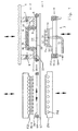
- the device according to the invention Fig. 1 comprises a molding device 1 for producing molded parts with a heating device 50 and a transfer carriage for a cover layer.
- the transfer carriage consists primarily of a clamping frame 60, which holds and carries the two already connected layers or two initially only superimposed layers cover layer 20.
- the cover layer 20 comprises a skin 21 on a foam serving as a carrier 22.
- the clamping frame 60 moves along rails 61 into the heating device 50. It holds the cover layer 20 while it is being heated in the heating device 50 and lies on the temperature control plate 54. Then, the stenter moves along the rails 61 to transport the heated cover layer 20 into the former 1.
- the heating device 50 comprises radiant heaters or an infrared radiator arrangement 52, which is arranged above the plane of the clamping frame 60. It also comprises a tempering plate 54, which is arranged in the plane of the clamping frame 60 during the heating process.
- the tempering plate 54 is for example a metal plate which is tempered by means of liquid in channels 56 such that the carrier 22 reaches the desired temperature.
- the infrared radiator arrangement 52 and / or the Tempering 54 are each movable in the vertical direction to the plane of the clamping frame 60 and away from it, as indicated by double arrows. For this serve in principle known, in Fig. 1 not shown devices such as hydraulic or pneumatic cylinders.
- the skin 21 of the cover layer 20 is heated in the heating device 50 so strongly that it becomes doughy or even molten or even molten.
- the degree of viscosity is selected as a function of the material in such a way that a surface structure 21 'can be pressed or impressed in a subsequent working step and then fixed by cooling.
- the skin 21 lies either on the foam layer serving as a carrier 22, or a foam mat forms the underside of the skin 21.
- the material used for the foam for example, is a chemically cross-linked polyurethane. Due to the chemical cross-linking, this material has almost thermosetting properties and is able to withstand high temperatures, so that it is even more than 200 ° C resistant.
- the molding apparatus 1 comprises a molding tool 2 for forming a front side and a molding tool 3 for forming a back side of a product and in particular the cover layer 20 or a molding 40.
- the molding tool 2 is a female mold, that of a head plate or a carrier 4 is worn while the mold 3 is a patrizeniano lower mold.
- the relative movement between the molds can be achieved by any known mechanism, including hydraulic cylinders, pneumatic cylinders, mechanical drives such as spindle drives, and the like.
- either the mold 2 or the mold 3 may be the upper mold or the lower mold as well as the patrike-like mold or the female mold.
- the mold 2 is preferably the upper mold.
- the molding tool 2 comprises an upper mold half 5 having a surface 5 'which is machined, polished and provided with a surface structure by engraving, etching or the like as described above. This surface structure is provided on one or more selected surface areas or on the entirety of the surface 5 '.
- the mold half 5 is preferably a solid steel mold that is easy to manufacture, machine, polish and engrave or etch by known forming and metalworking techniques. Such a steel mold offers a high inherent strength, a long usable life and allows the provision of a large range of different surface structures in its surface 5 '.
- the upper mold half 5 may be an electroplated zinc mold surface that can be made faster and cheaper (for example, for mold series having a smaller number of parts to be molded) but has a shorter useful life.
- Such a galvanically produced zinc mold may be perforated or made porous by chemical etching or a machining process to provide a continuous suction vacuum.
- the mold 2 includes a vacuum space or chamber 6 having at least one vacuum channel 7 connected to a suitable vacuum source (not shown) adapted to create a slight vacuum, much less than 1 bar below atmospheric pressure, and more particularly less than 0.5 bar below Atmospheric pressure or even less than 0.3 bar (for example 0.05 to 0.3 bar) under atmospheric pressure, and more preferably about 0.1 bar below atmospheric pressure.
- the vacuum channel 7 can also serve as a passive ventilation duct or it can optionally have the mold 2 additionally a vent channel 8.
- a plurality of openings for generating a negative pressure comprises vacuum holes 9 which extend through the upper mold half 5. They communicate with the vacuum chamber 6 and extend through the surface 5 '.
- Each of these vacuum holes 9 in the solid steel mold half 5 consists of a mechanically drilled hole section 9A and a laser drilled hole section 9B.
- the mechanically drilled bore portion 9A can have any suitable diameter, for example 3 to 5 mm, while the laser drilled bore portion 95 has a very fine diameter, for example less than 0.5 mm, or even less than 0.3 mm, and in some cases about 0 , 2 mm.
- Such a combined structure of the vacuum wells 9 efficiently combines the advantages of fast and economical mechanical drilling with the advantages of a small diameter bore made by laser drilling.
- the diameter of the laser drilled bore portion 9B is selected so that the molten skin material is prevented from entering or being sucked into these vacuum wells 9 to prevent the formation of undesirable nodules and spots or other imperfections on the finished surface of the molding.
- the vacuum holes 9 are formed or etched by chemical means with the required small diameter through the mold.
- the numerous vacuum bores 9 are distributed and arranged in a pattern, for example, at intervals of 30 to 40 mm from each other across the entire relevant surface 5 ', to which a vacuum is applied to uniform application of the vacuum and the venting and removal of any trapped To ensure exhaust air.
- the mold half 5 further includes cooling channels 10 through which a tempering liquid such as water or oil can flow to temper the mold half 5 to a constant and uniform temperature suitable for cooling and solidifying the molded part at a suitable rate, for example one Mold temperature in the range of 45 to 60 ° C and especially about 50 ° C.
- a tempering liquid such as water or oil
- the mold 3 comprises a second mold half 11 having a second surface 11 'generally configured to mate with the upper mold half 5 leaving a suitable gap (eg, about 4 mm) therebetween, as described below.
- the mold 3 is provided with an air space or air passage 12 which is connected to an air duct 13 and opens with air holes 14 in different planes or portions of its surface 11 '.
- the line 13 may be with a compressed air source for example, initially 100 ° C hot air or with another pressure medium such as steam, another gas or a liquid at a pressure of 1 to 30 bar, in particular from 6 to 30 bar and especially from 5 up to 20 bar, are connected.
- the air holes 14 may be formed of mechanically drilled holes of suitable diameter and are distributed over the surface 11 'of the lower mold or the lower mold half 11, to ensure a uniform distribution of the compressed air or the other pressure medium in the molding process.
- the air holes 14 may have mechanically drilled portions and laser drilled portions, as is the case with the vacuum holes 9 in the upper mold half 5 and upper mold 5, respectively.
- Such a configuration allows the application of either a pressure medium or a vacuum via the air duct 13 and then through the air holes 14.
- the apparatus can be operated in a first molding stage with vacuum applied through the upper mold half 5 and with pressure passing through the lower mold half 11 is applied to form two cover layers located on opposite sides of a substrate and laminated together, wherein the skin of the cover layers on both opposite sides of the molded part according to the invention are provided with a surface structure.
- the surface 11 is similar to the surface 5 'provided with a surface structure.
- the mold half 5 and the mold half 11 is provided with cooling channels 15 through which a bath liquid can be circulated to keep the mold half 11 at a gleichfflef3igei and constant temperature, which is for example in the range of 45 ° to 60 ° C.
- the apparatus 1 further comprises a circumferentially circumferential sealing frame 16 which serves to provide an airtight high pressure seal between the lower mold half 11 and the upper mold half 5 along its circumference to hold a pressurized pressure medium in the mold gap, as described below becomes.
- the sealing frame 16 is preferably resiliently mounted on the mold 3 or on the lower mold 3, so that it with this in the direction of the Forming tool 2 moves until a sealing member 17 presses against the cover layer and seals (as will be described below).
- an elastic spring means 18 such as a spring, a pneumatic cylinder or the like provides a predetermined force to firmly hold the sealing member 17 against the upper mold half 5 with the cover layer 20 sandwiched therebetween.
- the sealing frame 16 may be configured to receive or cooperate with the clamping frame 60 to achieve the required airtight seal.
- Fig. 1 shows an initial stage in operating the device according to the invention.
- a cover layer 20 having a skin 21 and a support 22 was heated in the heater 50 (as indicated by dashed lines) and then transported by means of the tenter 60 along a flat horizontal plane, along the rails 61, between the mold half 5 and the mold half 11 to be positioned.
- the cover layer 20 is supported and held at its peripheral edges by the tenter 60 or, alternatively, any other known means.
- the heated cover layer 20 can be easily placed on the second mold half 11 even with smaller formats.
- the skin 21 is a thermoplastic film
- the backing 22 is a closed-cell or substantially closed-cell polymeric foam which is preferably air-impermeable over its thickness.
- the cover layer 20 is a conventional known back-foamed thermoplastic polyolefin (TPO) film.
- the skin 21 is preferably a polypropylene film or a polyethylene film, but may alternatively be a film of polyvinyl chloride.
- the carrier 22 may be made of the same polymeric material as the skin 21 (e.g. Polypropylene) but in a foamed state, or it may be a different polymer material (eg, polyurethane), which preferably has a higher melting point than that of skin 21 (or no actual melting temperature due to crosslinking).
- a preferred general combination is a meltable thermoplastic skin 21 on a non-melting, thermoset, or higher temperature melting thermoplastic carrier 22.
- the cover layer 20 was preheated by means of a heater, for example by means of the illustrated infrared radiator arrangement 52, to heat the skin 21 (for example to about 200 ° C) while the support 22 rests on the temperature control plate 54 so that the support is kept relatively cold becomes (for example, below about 160 ° C or specifically about 140 ° C or lower) so that it does not melt.
- the cover layer 20 has been heated so that the skin 21 reaches at least its melting temperature (and with sufficient residual heat so that it remains molten until it is formed in the subsequent step) while the backing 22 reaches a temperature at which it is moldable , but the temperature is below the melting temperature of the carrier 22.
- the skin 21 has been substantially or completely melted into a viscous state so that it can uniformly adhere to and be carried by the carrier 22, which maintains its firm, foamable state.
- the carrier 22 is not softened to a state in which it is unable to provide tension and support for the molten material of the skin 21.
- the cover layer 20 is preferably oriented as shown with the skin 21 disposed on the top of the bottomed support 22. *** " Therefore, the molten skin can not drip or drain from the carrier 22.
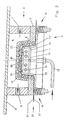
- the mold half 11 After the heated cover layer 20 as in Fig. 1 is arranged between the mold half 5 and the mold half 11, the mold half 11 is moved upward and / or the mold half 5 is moved downward, so that the mold half 11 and its surface 11 ', the cover layer 20 relative to the surface 5' of the mold half 5 in deformed a shaped contour, as it essentially Fig. 2 shows.
- the mold half 11 engages the somewhat cooler, unmelted carrier 22 and performs a deep drawing step in a first operation. In this case, the molten skin 21 may already be pressed against the structured surface 5 '. Further, the sealing frame 16 is pressed against the mold half 5 and forms an airtight seal along the circumference of the cover layer 20.
- the air passively from the space between the cover layer 20 and the surface 5 'through the vacuum holes 9 and through the vacuum channel. 7 or escape the vent channel 8. It is not necessary, but optionally possible, to apply a vacuum through the vacuum channel 7 at this stage. It is preferred that no vacuum be generated at this stage to reduce the energy expenditure in view of the rather large volume of air.
- the mold half 11 has moved upwards in an end position relative to the mold half 5, wherein a defined mold gap 23 between the surface 5 'and the surface 11' remains.
- This mold gap 23 is secured by the circumferential sealing frame 16 or another element which acts as a stop for the movement of the mold half 11 relative to the mold half 5.
- the mold gap 23 has a dual function and dimensions such that it is capable of receiving the cover layer 20 and forming an air gap 24 between the two surfaces 5 'and 11'.
- the air gap 24 is preferably sized (for example, 4 mm) to correspond to the thickness of the substrate 30, which is formed in another step, as will be described later.
- the sealing elements 17 of the peripheral sealing frame 16 had been applied to the edge of the carrier 22 to form an effective seal against high pressure, wherein the sealing elements press the cover layer 20 against an edge of the upper mold half 5.
- the elastically resilient suspension device 18 holds like a spring, the predetermined sealing pressure or the sealing force upright.
- a pressure medium preferably compressed air, is introduced through the air duct 13, the air duct 12 and the air holes 14 into the air gap 24 at a significant pressure (for example 6 to 30 bar).
- a slight vacuum or vacuum may be applied through the vacuum channel 7 to remove residual air bubbles while applying a negative pressure through the vacuum holes 9 on the skin 21.
- the pressure medium presses uniformly against the carrier 22, and the final shaping of the cover layer 20 against the surface 5 'is achieved by means of a purely pneumatic blow molding, preferably without direct mechanical mold contact between the surface 11 and the cover layer 20 in this method step.
- the result is a very uniform and contour-adapted shaping of the cover layer against the surface 5 ', which compensates for any tolerances or deviations or the like between the two forms.
- the carrier 22 is not (or substantially not) permeable to air, it acts as a buffer or intermediate layer and uniformly distributes the molding pressure to the skin 21. Thereby, the molten skin is uniformly pressed and formed against the structured surface 5 '.
- the negative pressure that can be applied through the vacuum holes 9 ensures that no air pockets trapped between the skin 21 and the surface 5 'remain the skin 21 is held firmly in a predetermined, aligned position relative to the surface 5 '.
- the cover layer 20 with the substantially molten skin 21 in a viscous-liquid state and at a temperature above its melting point in the device 1 was arranged.
- the cover layer 20 is deformed against the structured surface 5 'by pressure, there will be an exact inverse or inverse pattern of the structure in the molten skin 21. Since the molten skin 21 is in contact with the mold half 5 (which is replaced by the When the cooling channels 10 are cooled to a temperature of about 50 ° C., the molten material of the skin 21 begins to cool and then solidify when it has cooled below the melting temperature.
- the resulting contour and the surface structure of the skin 21 are "frozen” or fixed.
- the preheated carrier 22 is cooled by the tempered mold half 11, so that it becomes stiffer and maintains the shaped contour.
- the supply of pressure medium through the air duct 13 is interrupted, while the application of negative pressure through the vacuum channel 7 and the vacuum holes 9 is preferably continued to keep the molded cover layer 20 in a fixed position in the mold half 5.
- the cooling and solidification of the cover layer 20 continues.
- the device 1 is opened, for which purpose the mold half 11 is moved downward and / or the mold half 5 upwards.
- the finished, molded and patterned cover layer 20 and may later be applied to a desired substrate or part in a separate process as cover skin.
- the cover layer 20 may be further held by vacuum on the mold half 5, and a substrate 30 may be molded directly onto the back side of the preformed cover layer 20 in the same device 1.
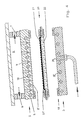
- the substrate material 30 between the mold half 11 and the mold half 5, namely between the mold half 11 and the carrier 22 of the cover layer 20 is inserted.
- This substrate material 30 is preferably a preheated layer of a composite material of polyolefin fibers, for example polypropylene fibers and natural fibers or glass fibers or polyester fibers or the like, or a polyurethane foam preheated by known means and carried into the device by known means or is placed in it.
- the mold apparatus 1 is closed, with the mold 3 being moved upwards for one back and / or the mold 2, so that the mold half 11 presses and molds the substrate 30 against the back side of the carrier 22 of the previously formed cover layer 20.
- the molding can be performed completely mechanically, that is, without requiring a pressure medium supplied through the air duct 13, but alternatively, it is advantageous to again introduce a pressure medium through the air duct 13 to apply a uniform molding pressure to the substrate 30, which results in an adjustment or compensation for any deviations or tolerances in the shape contours.
- the preheated and at least partially melted polyolefin fibers of the substrate 30 undergo fusion bonding with the still hot or still hot backing 22 of the cover layer 20 such that the substrate 30 is integral with the cover layer 20 is connected without any intermediate adhesive or the like is required.
- the substrate 30 has been mechanically formed and deformed into the required three-dimensionally contoured configuration, while the substrate material 30 now occupies the portion of the mold gap 23 previously occupied by the air gap 24 in the forming step Fig. 2 was.
- the entire molding process can be carried out with its sequence of steps for forming and applying a surface structure to the cover layer 20 and then molding and laminating the substrate 30 onto the cover layer 20 with a single set of molding tools in a single device 1 two consecutive molding stages, without requiring any reorientation or repositioning of the molds or other equipment and without having to move the molded part to another apparatus for any required process step.
- Fig. 4 schematically the enlarged result of according to Fig. 2 carried out first stage of molding. Namely, both the surface structure of the surface 5 'and the resulting surface structure 21' of the skin 21 of the cover layer 20 are enlarged to clearly illustrate that the resulting surface structure 21 'of the skin 21 is the exact undistorted negative image or inverse surface texture is, which was embossed or pressed into the surface 5 'of the mold half 5.
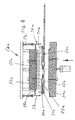
- Fig. 5 an enlarged schematic detail of the result from the implementation of the second shaping stage according to Fig. 3 .
- the cover layer 20 retains its surface structure 21 'and contour while a substrate material 30 has been formed and laminated on its back surface.
- the substrate material 30 is formed into the required three-dimensionally contoured shape and molded while being laminated and adhered to the support 22 of the cover layer 20.
- the pressure medium itself is a foaming polymer resin, which is introduced in liquid form into the mold gap, for example by injection through corresponding injection channels in the mold stage according to Fig. 2 , As a result, this combines the steps of Fig. 2 and Fig. 3 to a single stage.
- foaming polymer resin begins to foam and expands, it produces a corresponding pressure and it acts as a pressure medium, the cover layer 20 against the surface 5 'in the molding stage according to Fig. 2 pushes as described above. Then, when the foaming polymer resin cools and hardens or cures, being in contact with the tempered mold half 11, it directly forms the substrate 30 as in FIG Fig. 3 shown. Accordingly, backfoaming allows the entire molding process to be performed with a single cycle of opening and firing.
- the substrate 30 and the capping layer 20 are further cooled and somewhat solidified in the step shown in FIG Fig. 3 , which is a consequence of the contact with the mold half 5 and the mold half 11, which are tempered by means of cooling.
- the finished molding 40 shown schematically in FIG Fig. 5 is removed from the mold after the vacuum deposition has been interrupted by the vacuum channel 7.
- the formed cover layer 20 could be used without the substrate lamination according to FIG Fig. 3 be used. In other words, after completing the procedure according to Fig. 2 considered complete.
- the formed and patterned overcoat could be conventionally combined with any conventional substrate or used "as is” in appropriate applications.
- another covering layer may be formed on the opposite surface of the substrate 30, which additional covering layer may also be provided with a surface structure in its skin.
- the cover layer would be preheated in the same way as the cover layer 20, so that its skin is brought to a temperature above the melting temperature while its support has a temperature below the melting point.
- the preheated additional covering layer is introduced into the open mold between the substrate and the lower mold or lower mold half 11, whose surface 11 'has also been provided with a surface structure. Then the mold is closed with a sufficiently large mold gap opening, so that the space for the additional cover layer is present.
- Compressed air is supplied to the vacuum holes 9 while a vacuum is applied through the air holes 14 to substantially conform to the initial molding and the surface structuring method of FIG Fig. 2 perform, but the functions of the upper mold half 5 and the other mold half 11 are interchanged.
- blow molding can not be achieved to the same extent as in the first stage, but the molded surface structure is formed.
- a finished molding 40 can be made having structured surfaces 21 'of the respective skin 21 on opposite sides.
- a modified form of the heater 50 is in the Fig. 6-8 shown. Basically, the same parts have the same reference numerals and in addition the letter index a as in the heater 50 according to Fig. 1 on.
- the heating device 50a is used for heating a cover layer 20a, which consists of a subsequently designated as skin 21 a decorative layer and a second, serving as a support for the highly heated skin 21 a supporting layer.
- Characteristic of the heating device 50a in comparison with the other heating device 50 is an additionally provided protective hood 70a, which ensures that the two-layer covering layer 20a is in a closed chamber 71a when heated. The heating zone is thus encapsulated during the heating process.
- different heating elements are provided with different objectives.
- these are radiant heaters and, in particular, infrared radiators 53a on a ceiling element 55a which terminates the chamber 71a on the one hand and a contact heater with a contact surface in the form of a tempering plate 54a on the other hand.
- the temperature control plate 54a contacts the cover layer 20a from below.
- the protective hood 70a comprises side walls 57a, which can be arranged on all sides.
- intermediate pieces 58a are provided which bridge the free space between the side walls 57a and the ceiling element 55a.
- the intermediate pieces 58a are rigidly connected to the ceiling member 55a of the heater 50a.
- the side walls 57a are movable up and down relative to the intermediate pieces 58a. This makes it possible to open the chamber 71 a and close. To a two-ply or consisting of two individual layers cover layer 20a in the chamber 71 a, it must be opened. In order to heat the skin 21 a to the required extent and uniformly or to heat in a doughy or almost liquid state, the side walls 57 a of the protective cover 70 a are lowered until the chamber 71 a is closed. To remove the cover layer 20a by means of the clamping frame 60a, the chamber 71a is then opened again, as in Fig. 6 is shown.
- drive means 59a are provided, which may be pneumatic or hydraulic drives.
- the protective hood 70a or closed during the heating chamber 71 a are used to produce a uniform temperature distribution, but also expediently provided temperature sensor 62a in the interior of the chamber 71 a. At least two temperature sensors 62a are arranged between the infrared radiators 53a and with the aid of a control, which is of no interest here, it is possible, if appropriate, to throttle various radiant heaters or to increase their effect.
- the cover layer 20a consists of two layers 21a and 22a.
- the melting points of the materials of these two layers 21 a and 22 a are different.
- the one serving as a decorative layer 21 a position has a lower melting point compared to the other, serving as a carrier 22 a position.
- the tempering plate 54a is provided, and ensures that the sheet serving as the carrier 22a is kept at a sufficiently low temperature during the heating operation so as to maintain sufficient stability and strength to carry and transport the other sheet 21a despite its heating and softening.
- the degree of softening of serving as skin or decorative layer layer 21 a may be different according to the requirements. There must be a thermoplastic connection with the carrier 22a and a surface structuring or the like by a printing and embossing process must be possible in principle. Both serving as a decorative layer layer 21 a and serving as a support layer 22 a may be plastic films.
- the material used for the support layer 22a is in particular a chemically crosslinked, closed-cell plastic foam. Either the softening temperature thereof is substantially higher than that of the highly heated decorative layer 21a, or the temperature control for the support layer 22a in the heater 50a is selected such that the support layer 22a maintains sufficient stability and strength to serve as a support for the softened, doughy, viscous or to serve molten skin 21a.
- the temperature control in the heating device 50, 50a may therefore be such that the one layer 21, 21a to a temperature of 200 ° C (about 200 ° C) and the other layer 22, 22a to a temperature of 100 ° C (about 100 ° C) is heated.
- the tempering plate 54, 54a then preferably has a temperature of about 80 ° C to 90 ° C.
- a deep drawing step and then only pressure with the aid of a flow medium are used.
- a vacuum or underpressure is applied in the device 1 only when the skin 21, 21a has hardened sufficiently to prevent the skin from slipping out of the contour, and it is preferred that the backing is pressed against a substrate of, for example, only in a further step 200 ° C hot polypropylene natural fiber mixture.
- the foam has not only a function as a carrier material, but also as a bridge in the negative pressure in the Device 1. It helps to prevent the skin from being sucked into the laser drilled bore sections 98.
- multi-layer molded parts 40 and in particular interior trim parts for motor vehicles can be produced, wherein first a semi-finished product / intermediate product by deep drawing and back-pressing with a flow medium, d. H. in particular with compressed air in a mold gap 23 between two mold halves 5, 11 can be prepared and that then a substrate 30 is applied to the semifinished product that the mold gap 23 is filled with the substrate material, so that the semifinished product for the production of the final product mold halves 5, 11 does not have to be removed.
Abstract
Description
Die Erfindung betrifft eine Vorrichtung zum Herstellen von Formteilen wie Innenaustattungsteilen für Kraftfahrzeuge, wobei die Teile eine eingeformte Oberflächenstruktur nach Art einer Prägung, Narbung oder dergleichen aufweisen.The invention relates to an apparatus for producing molded parts such as interior equipment parts for motor vehicles, wherein the parts have a molded surface structure in the manner of an embossing, grain or the like.
Auf verschiedenen technischen Gebieten und insbesondere bei den Herstellern von Kraftfahrzeugen besteht eine ständig wachsende Nachfrage nach verschiedenen, geformten Bauteilen, die eine Oberflächenstruktur aufweisen, die in oder auf die Oberfläche solcher Teile geformt wird. Beispielsweise werden zunehmend Innenausstattungsteile für Kraftfahrzeuge benötigt wie Dachverkleidungen, Türverkleidungseinsätze, Säulenabdeckungen, Konsolen, Ablagefächer, Armaturenbretter und dergleichen, die eine Oberflächenstruktur wie eine künstliche Ledernarbung, eine künstliche holzähnliche Maserung, ein getüpfeltes, mit Linien versehenes oder ähnliches Muster, vorgetäuschte Nahtlinien, erhabene Vorsprünge, eingeschnittene Vertiefungen oder sogar eingeformten Text oder Logos aufweisen. Eine solche Oberflächenstruktur verbessert das Aussehen der sichtbaren Oberfläche des Formteils oder verbessert die Oberflächeneigenschaften hinsichtlich der Haptik oder der Griffigkeit oder gibt eine gewünschte Information in Form von Text, Logos oder dergleichen.There is an ever-increasing demand in various technical fields, and in particular among motor vehicle manufacturers, for various molded components which have a surface structure which is formed in or on the surface of such parts. For example, interior trim parts for automobiles such as roof linings, door trim inserts, pillar covers, consoles, storage compartments, instrument panels and the like are increasingly needed, which have a surface structure such as an artificial leather grain, an artificial wood-like grain, a dotted, lined or similar pattern, fake seam lines, raised protrusions , recessed pits or even formed text or logos. Such a surface structure improves the appearance of the visible surface of the molded article, or improves the surface properties in terms of haptics or feel, or gives desired information in the form of text, logos, or the like.
Dementsprechend ist es eine Aufgabe der Erfindung, eine Vorrichtung zum Herstellen eines Formteiles anzugeben, das eine Oberflächenstruktur aufweist, die genau die angestrebte Oberflächenstruktur ohne Verzerrungen aufweist und keinerlei Beschränkungen bezüglich des Typs der Oberflächenstruktur besitzt und verwendet werden kann, um synthetische Ledernarbungen, synthetische Holzmaserungen, Muster von Tüpfelungen, und Streifen oder dergleichen, erhabene Vorsprünge, eingezogene Vertiefungen, künstliche Nahtlinien, Text, Logos und dergleichen mit großem Detail, Genauigkeit und Produzierbarkeit herzustellen. Die erstrebte Oberflächenstruktur soll in die Oberfläche eines Formteils während seiner Formung eingebracht werden, ohne dass zusätzliche Arbeitsschritte oder Aufwand zur Erzielung dieser Oberflächenstruktur erforderlich sind. Die Materialien für die strukturierte Deckschicht, die auch in Kombination mit im wesentlichen jedem in Betracht kommenden rückseitigem Stützmaterial oder Substrat verwendet werden, sollen leicht recycelbar sein. Ferner zielt die Erfindung darauf ab, Nachteile des Standes der Technik zu vermeiden oder zu umgehen sowie zusätzliche Vorteile zu erreichen, wie es sich aus dieser Beschreibung ergibt.Accordingly, it is an object of the invention to provide an apparatus for producing a molded article having a surface structure which has exactly the desired surface structure without distortions and has no restrictions on the type of surface structure and can be used to obtain synthetic leather grain, synthetic wood grain, Patterns of spotting, and stripes or the like, raised projections, indentations, artificial stitching, text, logos and the like with great detail, accuracy and manufacturability. The desired surface structure should be introduced into the surface of a molded part during its molding, without additional work steps or effort to achieve this surface structure are required. The structured topcoat materials, which are also used in combination with substantially any back support material or substrate, should be readily recyclable. Furthermore, the invention aims to avoid or circumvent the disadvantages of the prior art and to achieve additional advantages, as can be seen from this description.
Die vorgenannten Aufgaben werden erfindungsgemäß gelöst mit einer Vorrichtung mit den Merkmalen des Anspruchs 1 oder 2. Mit einer solchen Vorrichtung lässt sich ein dreidimensionales konturiertes Formteil mit einem Substrat und einer darauf laminierten Deckschicht herstellen, die eine Haut und einen Träger umfasst, der am Substrat anhaftet oder damit verbunden ist. Die Haut wird mit einer Oberflächenstruktur versehen, die gleichmäßig und stetig ohne Verzerrung im Bereich der dreidimensional konturierten Fläche des Formteils aufgebracht ist.The aforementioned objects are achieved according to the invention with a device having the features of
Die Vorrichtung zum Herstellen des Formteiles mit der eingeformten Oberflächenstruktur besitzt ein Formwerkzeug für die Vorderseite und ein Formwerkzeug für die Rückseite, wobei es sich bei dem ersten Formwerkzeug um eine Oberform beziehungsweise eine obere Formhälfte und bei dem zweiten Formwerkzeug um eine untere Formhälfte handelt. Die obere Formhälfte hat eine Formfläche. Dies bedeutet, sie ist mit einer gewünschten Kontur bearbeitet, dann feinpoliert oder abgeschliffen sowie danach durch mechanisches Gravieren, Prägen, Fräsen, Ätzen oder dergleichen mit einer Strukturoberfläche versehen. Diese Struktur ist ein exaktes, negatives Abbild der gewünschten Oberflächenstruktur des herzustellenden Formteils.The apparatus for producing the molded article having the molded-in surface structure has a molding tool for the front side and a molding tool for the back side, wherein the first molding tool is an upper mold or an upper mold half and the second mold is a lower mold half. The upper mold half has a molding surface. This means she is with a desired contour machined, then finely polished or abraded and then provided by mechanical engraving, embossing, milling, etching or the like with a structural surface. This structure is an exact, negative image of the desired surface structure of the molded part to be produced.
Die obere Formhälfte umfasst eine mit einer Vakuumquelle verbundene Vakuumkammer und sehr feine Vakuumbohrungen, die sich von der Vakuumkammer durch die obere Formhälfte erstrecken. Diese Vakuumbohrungen weisen insbesondere mechanisch gebohrte Abschnitte und lasergebohrte Abschnitte auf, die von den mechanisch gebohrten Abschnitten ausgehend in der Oberfläche der Formhälfte münden. Die lasergebohrten Bohrungsabschnitte haben Öffnungen mit einem Durchmesser von weniger als 0,5 mm, insbesondere weniger als 0,3 mm und speziell etwa 0,2 mm.The upper mold half includes a vacuum chamber connected to a vacuum source and very fine vacuum bores extending from the vacuum chamber through the upper mold half. These vacuum bores have in particular mechanically drilled sections and laser drilled sections, which open from the mechanically drilled sections in the surface of the mold half. The laser drilled bore sections have openings with a diameter of less than 0.5 mm, in particular less than 0.3 mm and especially about 0.2 mm.
Sowohl die obere Formhälfte wie die untere Formhälfte werden mittels Kühlwasser oder Kühlöl oder dergleichen temperiert, das durch Kühlkanäle strömt, um die Formen beispielsweise auf einer Temperatur von 50° bis 60° C zu halten. Die exakte Höhe der notwendigen Temperatur hängt von den verwendeten Werkstoffen, der Arbeitsgeschwindigkeit und dem jeweiligen Verfahrensstand ab.Both the upper mold half and the lower mold half are tempered by means of cooling water or cooling oil or the like, which flows through cooling channels, for example, to keep the molds at a temperature of 50 ° to 60 ° C. The exact height of the necessary temperature depends on the materials used, the working speed and the respective process status.
Die zweite oder untere Formhälfte ist der oberen Formhälfte im wesentlichen angepasst, wobei ein geeigneter Formspalt dazwischen verbleibt. Die untere Formhälfte ist gegenüber der oberen Formhälfte bewegbar. Namentlich ist eine der Formen gegenüber der anderen bewegbar oder es sind beide Formen jeweils gegenüber der anderen bewegbar.The second or lower mold half is substantially conformed to the upper mold half leaving a suitable mold gap therebetween. The lower mold half is movable relative to the upper mold half. In particular, one of the molds is movable relative to the other or both molds are each movable relative to the other.
Die untere Formhälfte weist Verteilungskanäle für das Druckmedium und Bohrungen für das Druckmedium auf, die über eine Luftleitung mit einer Druckmittelquelle wie Druckluft mit einem Druck im Bereich von 1 bis 30 bar verbunden sind. Luftlöcher sind in allen Flächen der unteren Formfläche vorgesehen, um eine gleichförmige Verteilung des Druckmediums zu gewährleisten, wobei wenigstens ein Luftkanal die Luftleitung mit den Luftlöchern verbindet.The lower mold half has distribution channels for the pressure medium and holes for the pressure medium, which are connected via an air line with a pressure medium source such as compressed air with a pressure in the range of 1 to 30 bar. Air holes are provided in all surfaces of the lower mold surface to allow a uniform distribution of the pressure medium ensure, with at least one air duct connects the air line with the air holes.
Ein elastisch gelagerter, umlaufender Dichtungsrahmen bildet eine Abdichtung zwischen der oberen Formhälfte und der unteren Formhälfte längs der Peripherie. Der mit der zweiten Formhälfte verbundene Dichtungsrahmen erstreckt sich geschlossen längs des Randes der zweiten Formhälfte, so dass eine luftdichte Abdichtung zwischen der ersten, oberen Formhälfte und der zweiten, unteren Formhälfte gebildet wird, wenn die Formhälften ihre Schließstellung einnehmen. Der Dichtungsrahmen ist vorzugsweise an der unteren Formhälfte über eine nachgiebige Verbindung wie eine federbelastete Gleitanordnung montiert: Der Dichtungsrahmen kann auch als mechanischer Anschlag wirken, der die Schließbewegung der Formen begrenzt, um zuverlässig einen gewünschten Spalt dazwischen zu erhalten.An elastically mounted, circumferential sealing frame forms a seal between the upper mold half and the lower mold half along the periphery. The sealing frame connected to the second mold half extends closed along the edge of the second mold half, so that an airtight seal between the first, upper mold half and the second, lower mold half is formed when the mold halves occupy their closed position. The sealing frame is preferably mounted to the lower mold half via a resilient connection such as a spring-loaded slide assembly: the seal frame may also act as a mechanical stop limiting the closing movement of the molds to reliably maintain a desired gap therebetween.
Entweder die obere Formhälfte oder die untere Formhälfte können als matrizenartige Form ausgebildet sein, während die entsprechende Gegenform als angepasste patrizenartige Form ausgebildet ist. In ähnlicher Weise kann entweder die obere Formhälfte oder die untere Formhälfte als Negativform oder die Positivform angesehen werden, und jede dieser Formen kann die Oberform oder die Unterform sein. Vorzugsweise ist die obere Formhälfte die Oberform, während die untere Formhälfte die Unterform ist. Dieser Formanordnung entspricht, dass die Deckschicht mit dem Träger an der Unterseite orientiert ist, die an ihrer Oberseite das geschmolzene Hautmaterial trägt. Dieses ist insbesondere für größere Formteile erforderlich, weil eine Umkehrung dieser Anordnung "Oberseite nach unten" dem geschmolzenen Hautmaterial die Möglichkeit geben würde, von der als Träger wirkenden Schaumpolsterung herab zu strömen oder zu tropfen. Jedoch kann die Anordnung "Oberseite nach unten" mit Erfolg für kleinere zu formende Teile vorgesehen werden.Either the upper mold half or the lower mold half may be formed as a die-like shape, while the corresponding counter-mold is formed as a custom patrizenartige shape. Similarly, either the upper mold half or the lower mold half may be considered as a negative mold or the positive mold, and each of these molds may be the upper mold or the lower mold. Preferably, the upper mold half is the upper mold, while the lower mold half is the lower mold. This mold arrangement corresponds to the cover layer being oriented with the support on the underside, which carries the molten skin material on its upper side. This is particularly necessary for larger moldings because reversing this "top down" arrangement would allow the molten skin material to flow or drip down from the foam padding acting as a carrier. However, the "top down" arrangement can be successfully designed for smaller parts to be molded.
Die erfindungsgemäße Vorrichtung umfasst bevorzugt eine Heizeinrichtung. Diese Heizeinrichtung besitzt unterschiedliche Heizelemente, vorzugsweise einerseits Heizstrahler, z.B. Infrarot-Strahler, an der Oberseite zum Erhitzen des oberen Hautmaterials (beispielsweise auf etwa 200° C) und andererseits eine flüssigkeitsgekühlte Temperierplatte aus Metall an der Unterseite, um das Trägermaterial zu unterstützen und auf einer niedrigeren Temperatur (beispielsweise etwa 100°-140° C) zu halten. Die Angabe "etwa" unter Bezugnahme auf Temperaturen bedeutet hier +/- 5° C., soweit sich keine anderweitig Aufgabe findet.The device according to the invention preferably comprises a heating device. This heater has different heating elements, preferably on the one hand radiant heater, such as infrared radiator, at the top for heating the upper skin material (for example, about 200 ° C) and, on the other hand, a liquid-cooled metal tempering plate at the bottom to assist and maintain the substrate at a lower temperature (eg, about 100 ° -140 ° C). The term "about" with reference to temperatures here means +/- 5 ° C., as far as there is no other task.
Die Deckschicht wird von einem Spannrahmen, einem Klemmrahmen, einem Tuchrahmen oder dergleichen getragen. Dieser Rahmen kann die Deckschicht beziehungsweise ihre Lagen in die Heizeinrichtung und dann von dort in die Vorrichtung zum Herstellen der Formteile tragen. Grundsätzlich kann aber auch eine andere Trageeinrichtung die Lagen in die Heizeinrichtung transportieren.The cover layer is supported by a tenter, a clamp frame, a cloth frame or the like. This frame can carry the cover layer or its layers into the heating device and then from there into the device for producing the molded parts. In principle, however, another carrying device can transport the layers into the heating device.
Zum deutlicheren Verständnis der Erfindung wird diese nachfolgend im Zusammenhang mit Ausführungsbeispielen unter Bezugnahme auf die beigefügten Zeichnungen beschrieben. Es zeigen:
- Fig. 1:
- schematisch einen Schnitt durch eine Vorrichtung mit Heizeinrichtung zum Herstellen der Formteile;
- Fig. 2:
- schematisch einen Schnitt durch die Vorrichtung gemäß
Fig. 1 nach dem Schließen der Formhälften, wenn Druckluft durch die eine Formhälfte und Vakuum durch die andere Formhälfte auf die Deckschicht aufgebracht werden, wobei die Deckschicht zwischen den beiden Formhälften geformt wird; - Fig. 3:
- schematisch einen Schnitt durch die Vorrichtung entsprechend
Fig. 2 während eines weiteren Verfahrensschrittes, bei dem ein Substrat geformt und auf die Rückseite der geformten Deckschicht laminiert wird; - Fig. 4:
- schematisch sowie im größerem Maßstab einen Schnitt durch die zwischen den beiden Formhälften befindliche Deckschicht;
- Fig. 5:
- schematisch einen Schnitt ähnlich dem gemäß
Fig. 4 durch die umgeformte Deckschicht gemäß einem weiteren Verfahrensschritt, in dem ein Substrat auf die Rückseite der Deckschicht laminiert wird; - Fig. 6:
- schematisch sowie zum Teil im Schnitt eine Ansicht einer abgewandelten Heizeinrichtung vor Beginn des Heizvorganges;
- Fig. 7:
- einen Schnitt wie in
Fig. 6 während des Aufheizens der Deckschicht und - Fig. 8:
- eine Prinzipskizze von wesentlichen Merkmalen der Heizeinrichtung in Draufsicht.
- Fig. 1:
- schematically a section through a device with heating device for producing the moldings;
- Fig. 2:
- schematically a section through the device according to
Fig. 1 after closing the mold halves, when compressed air is applied through the one mold half and vacuum through the other mold half to the cover layer, wherein the cover layer is formed between the two mold halves; - 3:
- schematically a section through the device accordingly
Fig. 2 during another process step of forming a substrate and laminating it to the back side of the formed cover layer; - 4:
- schematically and on a larger scale a section through the cover layer located between the two mold halves;
- Fig. 5:
- schematically a section similar to that according to
Fig. 4 by the reformed cover layer according to a further method step, in which a substrate is laminated to the back side of the cover layer; - Fig. 6:
- schematically and partly in section a view of a modified heater before the start of the heating process;
- Fig. 7:
- a cut like in
Fig. 6 during the heating of the cover layer and - Fig. 8:
- a schematic diagram of essential features of the heater in plan view.
Die erfindungsgemäße Vorrichtung gemäß
Die Heizeinrichtung 50 umfasst Heizstrahler beziehungsweise eine Infrarotstrahleranordnung 52, die oberhalb der Ebene des Spannrahmens 60 angeordnet ist. Sie umfasst ferner eine Temperierplatte 54, die während des Heizvorganges in der Ebene des Spannrahmens 60 angeordnet ist. Die Temperierplatte 54 ist beispielsweise eine Metallplatte, die mittels Flüssigkeit in Kanälen 56 derart temperiert wird, dass der Träger 22 die erwünschte Temperatur erreicht. Die Infrarotstrahleranordnung 52 und/oder die Temperierplatte 54 sind jeweils in vertikaler Richtung zu der Ebene des Spannrahmens 60 hin und von diesem weg bewegbar, wie es durch Doppelpfeile angedeutet ist. Hierzu dienen grundsätzlich bekannte, in
Die Haut 21 der Deckschicht 20 wird in der Heizeinrichtung 50 derart stark erwärmt, dass sie teigig beziehungsweise zähflüssig oder sogar schmelzflüssig wird. Der Grad der Viskosität wird in Abhängigkeit von dem Werkstoff derart gewählt, dass eine Oberflächenstruktur 21' in einem nachfolgenden Arbeitsschritt ein gepresst beziehungsweise eingeprägt und dann durch Abkühlung fixiert werden kann. Während des Erhitzens liegt die Haut 21 entweder auf der als Träger 22 dienenden Schaumstoffschicht oder eine Schaumstoffmatte bildet die Unterseite der Haut 21. Als Werkstoff für den Schaumstoff dient zum Beispiel ein chemisch vernetztes Polyurethan. Durch die chemische Vernetzung besitzt dieser Werkstoff nahezu duroplastische Eigenschaften und ist in der Lage, hohen Temperaturen stand zu halten, so dass er sogar noch deutlich über 200° C beständig ist.The
Auf der Schaumstoffmatte liegend beziehungsweise zusammen mit der Schaumstoffmatte wird dann die zum Beispiel aus Polyethylen bestehende Haut 21 in eine geöffnete, aus Oberform und Unterform bestehende Formvorrichtung 1 zum Verformen transportiert.Lying on the foam mat or together with the foam mat then the existing example of
Die Formvorrichtung 1 umfasst ein Formwerkzeug 2 zur Bildung einer Vorderseite und ein Formwerkzeug 3 zur Bildung einer Rückseite eines Produktes und insbesondere der Deckschicht 20 beziehungsweise eines Formteiles 40. Bei dem dargestellten Ausführungsbeispiel ist das Formwerkzeug 2 eine matrizenförmige Oberform, die von einer Kopfplatte oder einem Träger 4 getragen wird, während das Formwerkzeug 3 eine patrizenartige Unterform ist. Entweder eines von beiden oder beide Formwerkzeuge 2 und 3 ist/sind in vertikaler Richtung relativ zueinander bewegbar, wie es schematisch durch Doppelpfeile angedeutet ist.The
Die Relativbewegung zwischen den Formen kann mit irgendeinem bekannten Mechanismus erreicht werden, wozu hydraulische Zylinder, pneumatische Zylinder, mechanische Antriebe wie Spindelantriebe und dergleichen zählen.The relative movement between the molds can be achieved by any known mechanism, including hydraulic cylinders, pneumatic cylinders, mechanical drives such as spindle drives, and the like.
Alternativ kann entweder das Formwerkzeug 2 oder das Formwerkzeug 3 die Oberform oder die Unterform sowie die patrizenartige Form oder die matrizenartige Form sein, Generell ist jedoch vorzugsweise das Formwerkzeug 2 die Oberform.Alternatively, either the
Das Formwerkzeug 2 umfasst eine obere Formhälfte 5 mit einer Oberfläche 5', die bearbeitet, poliert und mit einer Oberflächenstruktur durch Eingravieren, Ätzen oder dergleichen versehen wird, wie es zuvor beschrieben wurde. Diese Oberflächenstruktur ist an einem oder mehreren ausgewählten Flächenbereichen oder an der Gesamtheit der Oberfläche 5' vorgesehen.The
Die Formhälfte 5 ist vorzugsweise eine massive Stahlform, die sich einfach herstellen, bearbeiten, polieren und gravieren oder ätzen lässt, und zwar mittels bekannter Formgebungs- und Metallbearbeitungstechniken. Eine solche Stahlform bietet eine hohe Eigenfestigkeit, eine lange nutzbare Lebensdauer und erlaubt das Vorsehen eines großen Bereichs von unterschiedlichen Oberflächenstrukturen in ihrer Oberfläche 5'. Alternativ kann die obere Formhälfte 5 eine galvanisch hergestellte Zinkformfläche sein, die sich schneller und billiger herstellen lässt (beispielsweise für Formungsserien mit einer kleineren Anzahl von zu formenden Teilen), aber eine kürzere nutzbare Lebensdauer hat. Solch eine galvanisch produzierte Zinkform kann mittels chemischer Ätzung oder einem Bearbeitungsverfahren perforiert oder porös gemacht werden, um ein durchgehendes Saugvakuum aufzubringen.The
Das Formwerkzeug 2 schließt einen Vakuumraum oder eine Vakuumkammer 6 mit wenigstens einem Vakuumkanal 7 ein, der mit einer geeigneten Vakuumquelle (nicht dargestellt) verbunden ist, die dafür ausgelegt ist, ein leichtes Vakuum zu erzeugen, wesentlich weniger als 1 bar unterhalb des Atmosphärendrucks und insbesondere weniger als 0,5 bar unter Atmosphärendruck oder sogar weniger als 0,3 bar (beispielsweise 0,05 bis 0,3 bar) unter Atmosphärendruck, und im besonderen etwa 0,1 bar unter Atmosphärendruck. Der Vakuumkanal 7 kann auch als passiver Lüftungskanal dienen oder aber es kann das Formwerkzeug 2 gegebenenfalls zusätzlich einen Entlüftungskanal 8 aufweisen.The
Eine Mehrzahl von Öffnungen zum Erzeugen eines Unterdruckes umfasst Vakuumbohrungen 9, die sich durch die obere Formhälfte 5 erstrecken. Sie stehen mit der Vakuumkammer 6 in Verbindung und erstrecken sich durch die Oberfläche 5'. Jede dieser Vakuumbohrungen 9 in der massiven Formhälfte 5 aus Stahl besteht aus einem mechanisch gebohrten Bohrungsabschnitt 9A und einem lasergebohrten Bohrungsabschnitt 9B.A plurality of openings for generating a negative pressure comprises vacuum holes 9 which extend through the
Der mechanisch gebohrte Bohrungsabschnitt 9A kann irgendeinen geeigneten Durchmesser, beispielsweise 3 bis 5 mm, aufweisen, während der lasergebohrte Bohrungsabschnitt 95 einen sehr feinen Durchmesser, beispielsweise weniger als 0,5 mm, oder speziell weniger als 0,3 mm, und im Einzelfall etwa 0,2 mm aufweist.The mechanically drilled
Es sei bemerkt, dass die Abmessungen der Vakuumbohrungen 9 in den schematischen Figuren zwecks deutlicherer Darstellung signifikant übertrieben dargestellt sind.It should be noted that the dimensions of the vacuum holes 9 in the schematic figures are significantly exaggerated for clarity.
Eine solche kombinierte Struktur der Vakuumbohrungen 9 kombiniert in effizienter Weise die Vorteile eines schnellen und ökonomischen mechanischen Bohrens mit den Vorteilen einer durch Laserbohren hergestellten Bohrung von kleinem Durchmesser.Such a combined structure of the
Der Durchmesser des lasergebohrten Bohrungsabschnitts 9B ist so ausgewählt, dass das geschmolzene Hautmaterial gehindert ist, in diese Vakuumbohrungen 9 einzuströmen oder eingesaugt zu werden, um die Bildung von unerwünschten Knötchen und Punkten oder sonstigen Fehlstellen auf der fertiggestellten Oberfläche des Formteils zu vermeiden. Alternativ können bei einer galvanisch hergestellten oberen Formhälfte 5 aus Zink die Vakuumbohrungen 9 auf chemischem Wege mit dem erforderlichen kleinen Durchmesser durch die Form hindurch ausgebildet oder geätzt werden. Die zahlreichen Vakuumbohrungen 9 sind verteilt und in einem Muster angeordnet, beispielsweise in Abständen von 30 bis 40 mm voneinander quer über die gesamte relevante Oberfläche 5`, auf die ein Vakuum aufgebracht wird, um eine gleichmäßige Aufbringung des Vakuums und die Entlüftung und Entfernung irgendwelcher eingeschlossener Abluft zu gewährleisten.The diameter of the laser drilled bore
Die Formhälfte 5 enthält ferner Kühlkanäle 10, durch die eine Temperierflüssigkeit wie Wasser oder Öl strömen kann, um die Formhälfte 5 auf eine konstante und gleichmäßige Temperatur zu temperieren, die geeignet ist, das geformte Teil mit geeigneter Geschwindigkeit zu kühlen und zu verfestigen, beispielsweise eine Formtemperatur im Bereich von 45 bis 60° C und speziell etwa 50 °C.The
Das Formwerkzeug 3 umfasst eine zweite Formhälfte 11 mit einer zweiten Oberfläche 11', die allgemein so konfiguriert ist, dass sie zur oberen Formhälfte 5 passt, wobei ein geeigneter Spalt (beispielsweise etwa 4 mm) dazwischen verbleibt, wie es nachfolgend beschrieben wird. Das Formwerkzeug 3 ist mit einem Luftraum oder einem Luftkanal 12 versehen, der mit einer Luftleitung 13 verbunden ist und mit Luftlöchern 14 in verschiedenen Ebenen oder Abschnitten seiner Oberfläche 11' mündet.The
Die Leitung 13 kann mit einer Druckluftquelle für zum Beispiel zunächst 100° C heiße Luft oder mit einem anderen Druckmedium wie Dampf, einem anderen Gas oder einer Flüssigkeit bei einem Druck von 1 bis 30 bar, im einzelnen von 6 bis 30 bar und speziell von 5 bis 20 bar, verbunden werden. Die Luftlöcher 14 können von mechanisch gebohrten Löchern geeigneten Durchmessers gebildet sein und sind über die Oberfläche 11' der Unterform beziehungsweise der unteren Formhälfte 11 verteilt, um eine gleichförmige Verteilung der Druckluft oder des anderen Druckmediums im Formverfahren zu gewährleisten.The
Alternativ können die Luftlöcher 14 mechanisch gebohrte Abschnitte und lasergebohrte Abschnitte aufweisen, wie es bei den Vakuumbohrungen 9 in der oberen Formhälfte 5 beziehungsweise Oberform 5 der Fall ist.Alternatively, the air holes 14 may have mechanically drilled portions and laser drilled portions, as is the case with the vacuum holes 9 in the
Eine solche Ausgestaltung erlaubt das Aufbringen entweder eines Druckmediums oder eines Vakuums über die Luftleitung 13 und dann durch die Luftlöcher 14. Die Vorrichtung kann in einer ersten Formstufe mit Vakuum betrieben werden, das durch die obere Formhälfte 5 aufgebracht wird, und mit Druck, der durch die untere Formhälfte 11 aufgebracht wird, um zwei sich auf entgegengesetzten Seiten eines Substrats befindliche Deckschichten zu formen und zusammen zu laminieren, wobei die Haut der Deckschichten auf beiden gegenüberliegenden Seiten des Formteiles entsprechend der Erfindung mit einer Oberflächenstruktur versehen werden. In einem solchen Fall ist auch die Oberfläche 11 ähnlich wie die Oberfläche 5' mit einer Oberflächenstruktur versehen.Such a configuration allows the application of either a pressure medium or a vacuum via the
Ebenso wie die Formhälfte 5 ist auch die Formhälfte 11 mit Kühlkanälen 15 versehen, durch die eine Temperierflüssigkeit umgewälzt werden kann, um die Formhälfte 11 auf einer gleichmäf3igei und konstanten Temperatur zu halten, die beispielsweise im Bereich von 45° bis 60° C liegt.As well as the
Die Vorrichtung 1 weist ferner einen längs der Peripherie umlaufenden Dichtungsrahmen 16 auf, der zur Erzielung einer luftdichten Hochdruckabdichtung zwischen der unteren Formhälfte 11 und der oberen Formhälfte 5 längs ihres Umfangs dient, um ein unter Druck stehendes Druckmedium im Formenspalt zu halten, wie es nachfolgend beschrieben wird.The
Diese Dichtung wird während des Formens der Deckschicht 20 und auch in einem späteren Schritt des zweiten Formens und Laminierens eines Substratmaterials 30 auf die Deckschicht 20 wie nachfolgend beschrieben errichtet und aufrecht erhalten. Insbesondere ist der Dichtungsrahmen 16 vorzugsweise elastisch nachgiebig an dem Formwerkzeug 3 beziehungsweise an der Unterform 3 montiert, so dass er sich mit diesem in Richtung auf das Formwerkzeug 2 bewegt, bis ein Dichtglied 17 gegen die Deckschicht drückt und abdichtet (wie es nachfolgend beschrieben wird).This gasket is erected and maintained during the molding of the
Dann liefert eine elastische Federungseinrichtung 18 wie eine Feder, ein pneumatischer Zylinder oder dergleichen eine Sollkraft, um das Dichtglied 17 fest gegen die obere Formhälfte 5 zu halten, wobei die Deckschicht 20 dazwischen eingeschlossen ist. Der Dichtungsrahmen 16 kann so ausgebildet sein, dass der den Spannrahmen 60 aufnimmt oder mit diesem zusammenarbeitet, um die erforderliche luftdichte Abdichtung zu erreichen.Then, an elastic spring means 18 such as a spring, a pneumatic cylinder or the like provides a predetermined force to firmly hold the sealing
Ein Beispiel für das Formverfahren in der erfindungsgemäßen Vorrichtung wird nun unter Bezugnahme auf die Figuren beschrieben.
Eine Deckschicht 20 mit einer Haut 21 und einem Träger 22 wurde in der Heizeinrichtung 50 erhitzt (wie es durch gestrichelte Linien angedeutet ist) und dann mit mittels des Spannrahmens 60 längs einer flachen horizontalen Ebene transportiert, nämlich längs der Schienen 61, um zwischen der Formhälfte 5 und der Formhälfte 11 positioniert zu werden.A
Wie
Bevorzugt ist die Deckschicht 20 eine übliche bekannte rückseitig beschäumte Folie aus thermoplastischem Polyolefin (TPO). Im besonderen ist der Haut 21 vorzugsweise ein Polypropylenfilm oder ein Polyethylenfilm, jedoch kann es sich alternativ auch um einen Film aus Polyvinylchlorid handeln. Der Träger 22 kann aus dem gleichen Polymermaterial wie der Haut 21 (beispielsweise Polypropylen) jedoch in geschäumten Zustand bestehen, oder es kann ein unterschiedliches Polymermaterial (beispielsweise Polyurethan) sein, das vorzugsweise einen höheren Schmelzpunkt als denjenigen der Haut 21 hat (oder keine aktuelle Schmelztemperatur infolge der Querverbindung).Preferably, the
Eine bevorzugte generelle Kombination ist eine schmelzbare thermoplastische Haut 21 auf einem nicht schmelzenden, wärmegehärteten oder bei höherer Temperatur schmelzenden thermoplastischen Träger 22.A preferred general combination is a meltable
Bei der in
Die Haut 21 wurde im wesentlichen oder vollständig in einen zähflüssigen Zustand geschmolzen, so dass sie gleichförmig auf dem Träger 22 haften bleibt und von ihm getragen werden kann, der seinen festen, formbaren Schaumzustand beibehält. Insbesondere ist der Träger 22 nicht in einen Zustand erweicht, in dem er unfähig ist, Spannung und Unterstützung für das geschmolzene Material der Haut 21 zu bieten. Im Hinblick auf den geschmolzenen viskosen flüssigen Zustand der Haut 21 ist die Deckschicht 20 vorzugsweise wie dargestellt orientiert, wobei die Haut 21 an der Oberseite des einen Boden bildenden Trägers 22 angeordnet ist. Die geschmolzene Haut kann daher nicht vom Träger 22 abtropfen oder ablaufen.The
Nachdem die erhitzte Deckschicht 20 wie in
Wie in
Der Formspalt 23 hat eine Doppelfunktion und Abmessungen derart, dass er in der Lage ist, um die Deckschicht 20 aufzunehmen und einen Luftspalt 24 zwischen den beiden Oberflächen 5' und 11' zu bilden.The
Der Luftspalt 24 ist vorzugsweise so bemessen (beispielsweise 4 mm), dass er der Stärke des Substrates 30 entspricht, das in einem anderen Schritt angeformt wird, wie dies später beschrieben wird.The
Bei dem in
Zwischenzeitlich entweicht jegliche verbliebene Luft, die zwischen der Haut 21 und der Oberfläche 5' der oberen Formhälfte 5 eingeschlossen war, passiv durch die Vakuumbohrungen 9 in die Vakuumkammer 6. Gleichzeitig oder geringfügig später kann ein leichtes Vakuum beziehungsweise ein Unterdruck durch den Vakuumkanal 7 aufgebracht werden, um verbliebene Luftblasen zu entfernen und gleichzeitig einen Unterdruck durch die Vakuumbohrungen 9 auf der Haut 21 aufzubringen.In the meantime, any remaining air trapped between the
Dabei drückt das Druckmedium gleichförmig gegen den Träger 22, und es wird die Endformung der Deckschicht 20 gegen die Oberfläche 5' mittels einer rein pneumatischen Blasformung erreicht, vorzugsweise ohne direkten mechanischen Formkontakt zwischen der Oberfläche 11 und der Deckschicht 20 bei diesem Verfahrensschritt. Das Ergebnis ist ein sehr gleichförmiges und konturangepasstes Formen der Deckschicht gegen die Oberfläche 5', was jegliche Toleranzen oder Abweichungen oder dergleichen zwischen den beiden Formen ausgleicht. Da der Träger 22 nicht (oder im Wesentlichen nicht) luftdurchlässig ist, wirkt er als Puffer oder Zwischenschicht und verteilt den Formdruck gleichförmig auf die Haut 21. Dabei wird die geschmolzene Haut gleichmäßig gegen die strukturierte Oberfläche 5' gedrückt und geformt. Gleichzeitig oder kurz danach stellt der Unterdruck, der durch die Vakuumbohrungen 9 aufgebracht werden kann, sicher, dass keine zwischen der Haut 21 und der Oberfläche 5' eingeschlossenen Lufttaschen verbleiben, wobei die Haut 21 fest in einer vorgegebenen, ausgerichteten Stellung gegenüber der Oberfläche 5' gehalten wird.The pressure medium presses uniformly against the
Dieses gewährleistet, dass sich die Haut 21 nicht gegenüber der Oberfläche 5' verlagert, sobald sie mit ihr in Berührung gekommen ist. Dieses wiederum verhindert die Bildung von Verzerrungen oder "doppelten Abbildungen" der Oberfläche 5' auf der Haut 21.This ensures that the
Wie vorstehend erwähnt wurde die Deckschicht 20 mit der im wesentlichen geschmolzenen Haut 21 in viskos-flüssigem Zustand und bei einer Temperatur oberhalb ihres Schmelzpunktes in der Vorrichtung 1 angeordnet.As mentioned above, the
Da die Deckschicht 20 gegen die strukturierte Oberfläche 5' durch Druck verformt wird, ergibt sich dementsprechend ein exakt umgekehrtes oder inverses Muster der Struktur in der geschmolzenen Haut 21. Da die geschmolzene Haut 21 in Berührung mit der Formhälfte 5 ist, (die mittels der durch die Kühlkanäle 10 strömenden Kühlflüssigkeit auf eine Temperatur von etwa 50" C temperiert wird), beginnt sich das geschmolzene Material der Haut 21 abzukühlen und dann zu verfestigen, wenn es unter die Schmelztemperatur abgekühlt ist.Accordingly, since the
Dadurch wird die sich ergebende Kontur und die Oberflächenstruktur der Haut 21 "eingefroren" beziehungsweise fixiert. Gleichzeitig wird der vorerwärmte Träger 22 durch die temperierte Formhälfte 11 abgekühlt, so dass er steifer wird und die geformte Kontur aufrecht erhält.As a result, the resulting contour and the surface structure of the
Daraufhin wird die Zufuhr von Druckmedium durch die Luftleitung 13 unterbrochen, während die Beaufschlagung mit Unterdruck durch den Vakuumkanal 7 und die Vakuumbohrungen 9 vorzugsweise fortgeführt wird, um die geformte Deckschicht 20 in einer festen Stellung in der Formhälfte 5 zu halten. Gleichzeitig setzt sich die Abkühlung und Erstarrung der Deckschicht 20 fort. Dann wird die Vorrichtung 1 geöffnet, wozu die Formhälfte 11 abwärts und/oder die Formhälfte 5 aufwärts bewegt wird. Zu diesem Zeitpunkt kann die fertig gestellte, geformte und strukturierte Deckschicht 20 entnommen und sie kann später in einem separaten Verfahren als Deckhaut auf ein gewünschtes Substrat oder Teil aufgesetzt werden. Alternativ kann in dieser Stufe die Deckschicht 20 auch weiterhin durch Unterdruck an der Formhälfte 5 gehalten werden, und ein Substrat 30 kann direkt auf die Rückseite der vorgeformten Deckschicht 20 in derselben Vorrichtung 1 aufgeformt werden.Thereafter, the supply of pressure medium through the
Zur Durchführung dieses Schrittes wird das Substratmaterial 30 zwischen der Formhälfte 11 und der Formhälfte 5, namentlich zwischen der Formhälfte 11 und den Träger 22 der Deckschicht 20 eingeführt. Dieses Substratmaterial 30 ist vorzugsweise eine vorgewärmte Schicht aus einem Verbundmaterial von Polyolefinfasern, beispielsweise Polypropylenfasern und natürlichen Fasern oder Glasfasern oder Polyesterfasern oder dergleichen, oder es kann ein Polyurethanschaum vorgesehen sein, der mit Hilfe bekannter Mittel vorgewärmt wurde und der mit bekannten Mitteln in die Vorrichtung getragen oder in ihr angeordnet wird.To carry out this step, the
Wie in
In dieser Stufe kann das Formen vollständig mechanisch durchgeführt werden, also ohne dass ein durch die Luftleitung 13 zugeführtes Druckmedium erforderlich ist, aber alternativ ist es von Vorteil, wiederum ein Druckmedium durch die Luftleitung 13 einzuführen, um einen gleichförmigen Formdruck auf das Substrat 30 aufzubringen, was eine Anpassung oder einen Ausgleich für irgendwelche Abweichungen oder Toleranzen bei den Formkonturen führt. Der Dichtungsrahmen 16 hält die luftdichte Abdichtung ringsum am Umfang der geformten Anordnung aufrecht, Die vorgewärmten und wenigstens teilweise geschmolzenen Polyolefinfasern des Substrats 30 erfahren eine Schmelzverklebung mit dem noch warmen oder noch heißen Träger 22 der Deckschicht 20, so dass das Substrat 30 integral mit der Deckschicht 20 verbunden wird, ohne dass irgendein zwischenliegender Klebstoff oder dergleichen erforderlich ist. Ferner wurde das Substrat 30 mechanisch in die erforderliche dreidimensional konturierte Konfiguration geformt und verformt, während das Substratmaterial 30 nun den Teil des Formspalts 23 einnimmt, der zuvor der Luftspalt 24 in der Formgebungsstufe gemäß
Auf diese Weise kann das gesamte Formungsverfahren mit seinen Schrittfolgen zum Formen und Aufbringen einer Oberflächenstruktur auf die Deckschicht 20 und dann das Formen und Laminieren des Substrats 30 auf die Deckschicht 20 mit einem einzigen Satz von Formwerkzeugen in einer einzigen Vorrichtung 1 durchgeführt werden, und zwar in zwei aufeinander folgenden Formungsstufen, ohne dass irgendeine Neuausrichtung oder Umpositionierung der Formen oder sonstiger Ausrüstungsteile erforderlich wird und ohne dass das geformte Teil für irgendeinen erforderlichen Verfahrensschritt zu einer anderen Vorrichtung bewegt werden muss.In this way, the entire molding process can be carried out with its sequence of steps for forming and applying a surface structure to the
Zur Verdeutlichung zeigt
In entsprechender Weise zeigt
Es sei angemerkt, dass infolge des Formspaltes 23 einschließlich des Luftspaltes 24, der später das Substratmaterial 30 in der Stufe gemäß
Als Alternative zum Einführen einer Schicht aus Substratmaterial 30 in der zweiten Formungsstufe gemäß
Unabhängig von der besonderen Art der Anbringung und Formung des Substrats 30 werden das Substrat 30 und die Deckschicht 20 weiter abgekühlt und etwas verfestigt in der Stufe gemäß
Alternativ könnte auch die geformte Deckschicht 20 selbst ohne die Substratlaminierung gemäß
Dann könnte die geformte und strukturierte Deckschicht mit irgend einem üblichen Substrat in üblicher Weise kombiniert oder in geeigneten Anwendungsfällen "wie sie ist" verwendet werden.Then, the formed and patterned overcoat could be conventionally combined with any conventional substrate or used "as is" in appropriate applications.
Bei weiteren optionalen Schritten kann nach der Vervollständigung in der zweiten Formstufe gemäß
Eine abgewandelte Form der Heizeinrichtung 50 ist in den
Auch die Heizeinrichtung 50a dient zum Erhitzen einer Deckschicht 20a, die aus einer nachfolgend als Haut 21 a bezeichneten Dekorschicht und einer zweiten, als Träger für die stark erhitzte Haut 21 a dienenden Trageschicht besteht.The
Charakteristisch für die Heizeinrichtung 50a im Vergleich zu der anderen Heizeinrichtung 50 ist eine zusätzlich vorgesehene Schutzhaube 70a, die dafür sorgt, dass sich die aus zwei Lagen bestehende Deckschicht 20a beim Erhitzen in einer geschlossenen Kammer 71a befindet, Die Heizzone ist somit während des Heizvorganges gekapselt.Characteristic of the
Wie bei dem ersten Ausführungsbeispiel sind unterschiedliche Heizelemente mit unterschiedlicher Zielsetzung vorgesehen. Dies sind gemäß Ausführungsbeispiel Heizstrahler und insbesondere Infrarotstrahler 53a an einem die Kammer 71a noch oben abschließenden Deckenelement 55a einerseits und eine Kontaktheizung mit einer Kontaktfläche in Gestalt einer Temperierplatte 54a andererseits. Während des Heiz- oder Erwärmungsschrittes berührt die Temperierplatte 54a die Deckschicht 20a von unten. Die Schutzhaube 70a umfasst Seitenwände 57a, die allseitig angeordnet sein können. Ferner sind gemäß dem in
Wie aus einem Vergleich der
Zum Heben und Senken der Seitenwände 57a der Schutzhaube 70a sind Antriebsmittel 59a vorgesehen, bei denen es sich um pneumatische oder hydraulische Antriebe handeln kann.For raising and lowering the
Aber nicht nur die Schutzhaube 70a beziehungsweise die während des Heizvorganges geschlossene Kammer 71 a dienen zur Herstellung einer gleichmäßigen Temperaturverteilung, sondern auch zweckmäßigerweise vorgesehene Temperaturfühler 62a im Inneren der Kammer 71 a. Mindestens zwei Temperaturfühler 62a sind zwischen den Infrarotstrahlern 53a angeordnet und mit Hilfe einer hier nicht näher interessierenden Steuerung in der Lage, gegebenenfalls verschiedene Heizstrahler zu drosseln oder deren Wirkung zu verstärken.But not only the
Von grundsätzlicher und allgemeiner Bedeutung ist, dass die Deckschicht 20a aus zwei Lagen 21a und 22a besteht. Die Schmelzpunkte der Werkstoffe dieser beiden Lagen 21 a und 22a sind verschieden. Die eine, als Dekorschicht 21 a dienende Lage weist einen im Vergleich niedrigeren Schmelzpunkt auf als die andere, als Träger 22a dienende Lage.Of fundamental and general importance is that the
Ferner ist die Temperierplatte 54a vorgesehen und sorgt dafür, dass die als Träger 22a dienende Lage auf einer ausreichend niedrigen Temperatur während des Heizvorgangs gehalten wird, damit sie eine ausreichende Stabilität und Festigkeit zum Tragen und Transportieren der anderen Lage 21a trotz deren Erwärmung und Erweichung beibehält.Further, the tempering
Der Erweichungsgrad der als Haut oder Dekorschicht dienenden Lage 21 a kann entsprechend den Anforderungen unterschiedlich sein. Es muss eine thermoplastische Verbindung mit dem Träger 22a erfolgen und eine Oberflächenstrukturierung oder dergleichen durch einen Druck- und Prägevorgang muss grundsätzlich möglich sein. Sowohl die als Dekorschicht dienende Lage 21 a als auch die als Träger dienende Lage 22a können Kunststofffolien sein.The degree of softening of serving as skin or
Als Werkstoff für die Trageschicht 22a dient jedoch insbesondere ein chemisch vernetzter, geschlossenporiger Kunststoffschaum. Entweder ist dessen Erweichungstemperatur wesentlich höher als die der stark erhitzten Dekorschicht 21 a oder die Temperatursteuerung für die Trageschicht 22a in der Heizeinrichtung 50a wird derart gewählt, dass die Trageschicht 22a eine ausreichende Stabilität und Festigkeit behält, um als Träger für die erweichte, teigige, zähflüssige oder schmelzflüssige Haut 21a zu dienen.However, the material used for the
Die Temperatursteuerung in der Heizeinrichtung 50, 50a kann daher derart sein, dass die eine Lage 21, 21a auf eine Temperatur von 200° C (etwa 200° C) und die andere Lage 22, 22a auf eine Temperatur von 100° C (etwa 100° C) erwärmt wird. Die Temperierplatte 54, 54a hat dann vorzugsweise eine Temperatur von etwa 80° C bis 90° C.The temperature control in the
Zum Verformen in der Vorrichtung 1 werden dann ein Tiefziehschritt und daraufhin nur Druck mit Hilfe eines Strömungsmediums verwendet. Ein Vakuum beziehungsweise Unterdruck wird in der Vorrichtung 1 erst dann angelegt, wenn die Haut 21, 21a ausreichend erhärtet ist, um ein Verrutschen der Haut aus der Kontur zu verhindern, und vorzugsweise erfolgt erst in einem weiteren Schritt das Hinterpressen mit einem Substrat von zum Beispiel 200° C heißem Polypropylen-Naturfaser-Gemisch.For deformation in the
Der Schaumstoff besitzt schließlich nicht nur eine Funktion als Trägerwerkstoff, sondern auch als Brücke bei dem Unterdruck in der Vorrichtung 1. Er trägt dazu bei, dass die Haut nicht in die lasergebohrten Bohrungsabschnitte 98 gesaugt wird.Finally, the foam has not only a function as a carrier material, but also as a bridge in the negative pressure in the
Sehr wesentlich ist schließlich, dass mehrlagige Formteile 40 und insbesondere Innenverkleidungsteile für Kraftfahrzeuge hergestellt werden können, wobei zunächst ein Halbfabrikat/Vorprodukt durch Tiefziehen und Hinterpressen mit einem Strömungsmedium, d. h. insbesondere mit Druckluft in einem Formspalt 23 zwischen zwei Formhälften 5, 11 hergestellt werden kann und dass so dann auf das Halbfabrikat ein Substrat 30 dadurch aufgebracht wird, dass der Formspalt 23 mit dem Substratwerkstoff gefüllt wird, so dass das Halbfabrikat zur Herstellung des Endproduktes den Formhälften 5, 11 nicht entnommen werden muss.Finally, it is very important that multi-layer molded
Claims (21)
wobei das Formwerkzeug (2) ferner eine Vakuumkammer (6) und einen Vakuumkanal (7) aufweist, der an die Vakuumkammer (6) anschließt und einer Unterdruckquelle verbindbar ist;
wobei das Formwerkzeug (2) eine Vielzahl von Vakuumbohrungen (9) aufweist, die in der Oberfläche (5') münden und mit der Vakuumkammer (6) in Verbindung stehen;
wobei das Formwerkzeug (3) für die eine Rückseite eine Formhälfte (11) mit einer der Oberfläche (5') gegenüberliegenden Oberfläche (11') und eine mit einer Druckluftquelle verbindbare Luftleitung (13) und mehrere Luftlöcher (14) in der Oberfläche (11) aufweist; wobei wenigstens ein Luftkanal (12) die Luftleitung (13) mit den Luftlöchern (14) verbindet;
und wobei das Formwerkzeug (3) wenigstens einen umlaufenden Dichtungsrahmen (16) aufweist, der mit der zweiten Formhälfte (11) verbunden ist und sich geschlossen längs des Randes der Formhälfte (11) erstreckt, so dass eine luftdichte Abdichtung zwischen der Formhälfte (5) und der Formhälfte (11) gebildet wird, wenn die Formhälften (5, 11) ihre Schließstellung einnehmen.Apparatus for producing a molded part (40) having a molded-in surface structure (21 ') comprising a molding tool (2) for the front side and a molding tool (3) for the back side, wherein the molding tool (2) is an upper mold or an upper mold half (5) having a surface (5 ') and a surface structure engraved, milled, indented, embossed or etched into the surface (5');
wherein the mold (2) further comprises a vacuum chamber (6) and a vacuum channel (7), which connects to the vacuum chamber (6) and is connectable to a vacuum source;
the mold (2) having a plurality of vacuum bores (9) opening in the surface (5 ') and communicating with the vacuum chamber (6);
wherein the molding tool (3) for the one back side has a mold half (11) with a surface (11 ') opposite the surface (5') and an air line (13) which can be connected to a compressed air source and a plurality of air holes (14) in the surface (11 ) having; wherein at least one air duct (12) connects the air duct (13) with the air holes (14);
and wherein the molding tool (3) has at least one peripheral sealing frame (16) connected to the second mold half (11) and extending closed along the edge of the mold half (11) so as to provide an airtight seal between the mold half (5). and the mold half (11) is formed when the mold halves (5, 11) assume their closed position.
wobei das untere Formwerkzeug für die Vorderseite ferner eine Vakuumkammer (6) und einen Vakuumkanal (7) aufweist, der an die Vakuumkammer (6) anschließt und einer Unterdruckquelle verbindbar ist;
wobei das untere Formwerkzeug für die Vorderseite eine Vielzahl von Vakuumbohrungen (9) aufweist, die in der Oberfläche (5') münden und mit der Vakuumkammer (6) in Verbindung stehen;
wobei das obere Formwerkzeug für die Rückseite eine Formhälfte (11) mit einer der Oberfläche (5') gegenüberliegenden Oberfläche (11') und eine mit einer Druckluftquelle verbindbare Luftleitung (13) und mehrere Luftlöcher (14) in der Oberfläche (11) aufweist; wobei wenigstens ein Luftkanal (12) die Luftleitung (13) mit den Luftlöchern (14) verbindet;
und wobei das obere Formwerkzeug für die Rückseite wenigstens einen umlaufenden Dichtungsrahmen (16) aufweist, der mit der zweiten Formhälfte (11) verbunden ist und sich geschlossen längs des Randes der Formhälfte (11) erstreckt, so dass eine luftdichte Abdichtung zwischen der Formhälfte (5) und der Formhälfte (11) gebildet wird, wenn die Formhälften (5, 11) ihre Schließstellung einnehmen.Device comprising a molding device (1) for producing a molded part (40) with a 'molded surface structure (21'), comprising a front mold and a back mold, wherein the mold for the front is a lower mold or lower mold half having a surface (5 ') and a surface texture projecting into the surface (5') engraved, milled, indented, embossed or etched;
the lower mold for the front further comprising a vacuum chamber (6) and a vacuum channel (7), which connects to the vacuum chamber (6) and is connectable to a vacuum source;
the lower mold for the front having a plurality of vacuum holes (9) opening in the surface (5 ') and communicating with the vacuum chamber (6);
wherein the upper mold for the back has a mold half (11) with a surface (11 ') opposite the surface (5') and an air line (13) connectable to a compressed air source and a plurality of air holes (14) in the surface (11); wherein at least one air duct (12) connects the air duct (13) with the air holes (14);
and wherein the upper mold for the back has at least one circumferential seal frame (16) connected to the second mold half (11) and extending closed along the edge of the mold half (11) so as to provide an airtight seal between the mold half (5 ) and the mold half (11) is formed when the mold halves (5, 11) assume their closed position.
Applications Claiming Priority (2)
| Application Number | Priority Date | Filing Date | Title |
|---|---|---|---|
| US09/929,693 US6749794B2 (en) | 2001-08-13 | 2001-08-13 | Method and apparatus for molding components with molded-in surface texture |
| EP02017847.1A EP1284182B1 (en) | 2001-08-13 | 2002-08-08 | Method for forming parts with structural patterns on its surface |
Related Parent Applications (2)
| Application Number | Title | Priority Date | Filing Date |
|---|---|---|---|
| EP02017847.1A Division EP1284182B1 (en) | 2001-08-13 | 2002-08-08 | Method for forming parts with structural patterns on its surface |
| EP02017847.1A Division-Into EP1284182B1 (en) | 2001-08-13 | 2002-08-08 | Method for forming parts with structural patterns on its surface |
Publications (1)
| Publication Number | Publication Date |
|---|---|
| EP1974893A2 true EP1974893A2 (en) | 2008-10-01 |
Family
ID=25458294
Family Applications (2)
| Application Number | Title | Priority Date | Filing Date |
|---|---|---|---|
| EP08012435A Withdrawn EP1974893A2 (en) | 2001-08-13 | 2002-08-08 | Apparatus for forming parts with patterns on its surface |
| EP02017847.1A Expired - Lifetime EP1284182B1 (en) | 2001-08-13 | 2002-08-08 | Method for forming parts with structural patterns on its surface |
Family Applications After (1)
| Application Number | Title | Priority Date | Filing Date |
|---|---|---|---|
| EP02017847.1A Expired - Lifetime EP1284182B1 (en) | 2001-08-13 | 2002-08-08 | Method for forming parts with structural patterns on its surface |
Country Status (5)
| Country | Link |
|---|---|
| US (1) | US6749794B2 (en) |
| EP (2) | EP1974893A2 (en) |
| JP (1) | JP4371638B2 (en) |
| KR (1) | KR20030015155A (en) |
| ES (1) | ES2526800T3 (en) |
Cited By (2)
| Publication number | Priority date | Publication date | Assignee | Title |
|---|---|---|---|---|
| CN107150426A (en) * | 2017-06-30 | 2017-09-12 | 中山市程博工业产品设计有限公司 | A kind of automobile die easy to use |
| DE102019204821A1 (en) * | 2019-04-04 | 2020-10-08 | Multivac Sepp Haggenmüller Se & Co. Kg | Mold insert for a thermoforming packaging machine and manufacturing process |
Families Citing this family (111)
| Publication number | Priority date | Publication date | Assignee | Title |
|---|---|---|---|---|
| US6652273B2 (en) * | 2002-01-14 | 2003-11-25 | The Procter & Gamble Company | Apparatus and method for controlling the temperature of manufacturing equipment |
| EP1371476A1 (en) * | 2002-02-15 | 2003-12-17 | R+S Technik GmbH | Apparatus for manufacturing vehicle interior parts |
| KR100499866B1 (en) * | 2002-12-18 | 2005-07-07 | 한국과학기술원 | A Method and an Apparatus for Fabricating Micro-channel Plate Using Corrugated Molds |
| DE10301712B4 (en) * | 2003-01-13 | 2004-11-04 | Sai Automotive Sal Gmbh | Process for the production of injection molded plastic parts |
| US20040209123A1 (en) * | 2003-04-17 | 2004-10-21 | Bajorek Christopher H. | Method of fabricating a discrete track recording disk using a bilayer resist for metal lift-off |
| DE10328046A1 (en) * | 2003-06-23 | 2005-01-13 | Arvinmeritor Gmbh | Method for producing a plastic composite component, in particular a body component |
| DE10333161A1 (en) | 2003-07-22 | 2005-02-24 | Findlay Industries Deutschland Gmbh | Interior equipment components of motor vehicles with a defined surface profile |
| US7922956B1 (en) * | 2003-11-05 | 2011-04-12 | Leon Plastics, Inc. | Vehicular trim component and cover with simulated stitch and/or seam thereon |
| US20050151282A1 (en) * | 2004-01-13 | 2005-07-14 | Harper Bruce M. | Workpiece handler and alignment assembly |
| US7686606B2 (en) * | 2004-01-20 | 2010-03-30 | Wd Media, Inc. | Imprint embossing alignment system |
| US7329114B2 (en) * | 2004-01-20 | 2008-02-12 | Komag, Inc. | Isothermal imprint embossing system |
| US20050183897A1 (en) * | 2004-02-24 | 2005-08-25 | Lear Corporation | Two-shot co-injected automotive interior trim assembly and method |
| NO323512B1 (en) * | 2004-04-07 | 2007-06-04 | Crescendo As | Stop mold for making a helmet lining. |
| US20060062970A1 (en) * | 2004-04-19 | 2006-03-23 | Martin James N | Embossed headliner and method of making same |
| US20080169678A1 (en) * | 2004-04-30 | 2008-07-17 | Kyoraku Co., Ltd. | Interior Finishing Panel for Vehicle and Method of Manufacturing the Same |
| US7699595B2 (en) * | 2004-07-19 | 2010-04-20 | R + S Technik Gmbh | Method and apparatus for molding a laminated trim component without use of slip frame |
| US20060027036A1 (en) * | 2004-08-05 | 2006-02-09 | Biggs Todd L | Methods and apparatuses for imprinting substrates |
| US7156437B2 (en) * | 2004-10-19 | 2007-01-02 | Lear Corporation | Automotive trim part with applique and method of making same |
| US20060082175A1 (en) * | 2004-10-19 | 2006-04-20 | Cowelchuk Glenn A | Automotive trim part with multi-feel cover and method of making the same |
| US20060082179A1 (en) * | 2004-10-19 | 2006-04-20 | Depue Todd L | Automotive trim assembly having impact countermeasures and method of making the same |
| US7478854B2 (en) * | 2004-10-19 | 2009-01-20 | International Automotive Components Group North America, Inc. | Automotive handle with soft feel and method of making the same |
| US7458631B2 (en) * | 2004-10-19 | 2008-12-02 | International Automotive Components Group North America, Inc. | Automotive armrest with soft feel and method of making the same |
| US7458604B2 (en) * | 2004-10-20 | 2008-12-02 | International Automotive Components Group North America, Inc. | Automotive trim assembly having an integrated airbag door |
| US20060082109A1 (en) * | 2004-10-20 | 2006-04-20 | Hier Michael J | Method of making an automotive trim assembly having an integrated airbag door |
| US20060097544A1 (en) * | 2004-11-09 | 2006-05-11 | Cowelchuk Glenn A | Automotive interior trim assembly and method |
| US7108312B2 (en) * | 2004-11-09 | 2006-09-19 | Lear Corporation | Vehicle door trim bolster with multi-feel cover and method of making the same |
| US20060099395A1 (en) * | 2004-11-09 | 2006-05-11 | Cowelchuk Glenn A | Automotive interior trim assembly and method |
| US7192074B2 (en) * | 2004-11-10 | 2007-03-20 | Lear Corporation | Automotive compartment having an integrated spring mechanism and method of making the same |
| US7332207B2 (en) * | 2004-12-15 | 2008-02-19 | Visteon Global Technologies, Inc. | Component for a vehicle interior and a method of assembly |
| US20060151097A1 (en) * | 2005-01-13 | 2006-07-13 | Bennett Norman H | Method of making a non-carpeted floor covering |
| FR2880838B1 (en) * | 2005-01-19 | 2009-03-13 | Visteon Global Tech Inc | METHOD FOR MANUFACTURING A COMPOSITE PANEL WITH A DECORATIVE SKIN AND CORRESPONDING PANEL |
| EP1704979A1 (en) * | 2005-03-22 | 2006-09-27 | ArvinMeritor GmbH | Thermoforming or sheet foaming mould and process for the production of a composite part |
| JP2007069355A (en) * | 2005-09-02 | 2007-03-22 | Toyota Motor Corp | Mold |
| US20070134485A1 (en) * | 2005-12-08 | 2007-06-14 | Collins Daniel J | Blow molded articles having capped or inserted thermoplastic vulcanizate foam surfaces |
| US20070202327A1 (en) * | 2005-12-19 | 2007-08-30 | Alberto Baban | Synthetic cork with a natural cork appearance and method of making it |
| AT503268B1 (en) * | 2006-02-20 | 2008-07-15 | Greiner Perfoam Gmbh | METHOD FOR PRODUCING A MULTILAYER COMPONENT |
| DE102006022263B4 (en) * | 2006-05-11 | 2008-04-03 | Uhlmann Pac-Systeme Gmbh & Co. Kg | heating station |
| KR100783617B1 (en) * | 2006-05-18 | 2007-12-10 | 덕양산업 주식회사 | Micro cellular foaming sheet applied multi-layer of instrument panel and manufacturable method |
| DE102006026063B4 (en) * | 2006-06-03 | 2020-02-27 | Kraussmaffei Technologies Gmbh | Process for the production of coated composite plastic molded parts and injection molding machine therefor |
| ES2698436T3 (en) * | 2006-12-01 | 2019-02-04 | Tanazawa Hakkosha Kk | Mold for resin molding, mold manufacturing method for resin molding and resin molding product |
| DE102007009384B4 (en) * | 2007-02-20 | 2020-11-26 | Faurecia Innenraum Systeme Gmbh | Process for back-molding a film |
| KR100815497B1 (en) | 2007-04-18 | 2008-03-20 | 한일이화주식회사 | Apparatus and method for manufacturing of trunk module parts |
| DE102007046472B4 (en) * | 2007-09-28 | 2013-12-24 | Bayer Materialscience Aktiengesellschaft | Process for the preparation of a thermoformed sheet of polycarbonate or polymethylmethacrylate |
| WO2009070757A1 (en) * | 2007-11-26 | 2009-06-04 | International Automotive Components Group North America, Inc. | 3d faux wood applique |
| JP5025549B2 (en) | 2008-03-31 | 2012-09-12 | キョーラク株式会社 | Foam blow molded article and method for producing the same |
| US8012290B2 (en) * | 2008-06-30 | 2011-09-06 | Herbert Olbrich Gmbh & Co. Kg | Method and apparatus for producing a three-dimensionally molded, laminated article with transfer-printed surface decoration |
| CN101618597A (en) * | 2008-07-04 | 2010-01-06 | 深圳富泰宏精密工业有限公司 | Vacuum forming mould and bleeder hole perforating device thereof |
| EP2179836B1 (en) * | 2008-10-24 | 2011-01-05 | Faurecia Innenraum Systeme GmbH | Method for the production of a plastic skin |
| JP5253103B2 (en) * | 2008-11-17 | 2013-07-31 | 日産自動車株式会社 | Interior parts for vehicles |
| DE102009031453A1 (en) * | 2009-07-02 | 2011-01-05 | Werner Beuerlein | Mold with deaerator |
| CN102112279A (en) * | 2009-09-10 | 2011-06-29 | 乐金华奥斯株式会社 | Molding method using water pressure or steam pressure and molding device |
| EP2312605B1 (en) * | 2009-10-14 | 2012-06-06 | ABB Technology AG | Bistable magnetic actuator for a medium voltage circuit breaker |
| US8402638B1 (en) | 2009-11-06 | 2013-03-26 | Wd Media, Inc. | Press system with embossing foil free to expand for nano-imprinting of recording media |
| US8496466B1 (en) | 2009-11-06 | 2013-07-30 | WD Media, LLC | Press system with interleaved embossing foil holders for nano-imprinting of recording media |
| US9330685B1 (en) | 2009-11-06 | 2016-05-03 | WD Media, LLC | Press system for nano-imprinting of recording media with a two step pressing method |
| US20110204611A1 (en) * | 2010-02-18 | 2011-08-25 | Daimler Trucks North America Llc | Fiber reinforced polymer frame rail |
| JP5619449B2 (en) * | 2010-03-26 | 2014-11-05 | 株式会社浅野研究所 | Differential pressure forming apparatus and differential pressure forming sheet manufacturing method |
| JP5349403B2 (en) * | 2010-05-17 | 2013-11-20 | テクノポリマー株式会社 | Light irradiation molding apparatus and method |
| US20120104659A1 (en) * | 2010-11-02 | 2012-05-03 | Honeywell International Inc. | Apparatus for pitch densification |
| US20120104641A1 (en) | 2010-11-02 | 2012-05-03 | Honeywell International Inc. | Apparatus for pitch densification |
| BR112013010982B1 (en) * | 2010-11-05 | 2020-01-28 | Lightweight Labs Llc | method and system for thermal processing and consolidation and thermally processed and consolidated material obtained by this method |
| US20120153528A1 (en) | 2010-12-17 | 2012-06-21 | Honeywell International Inc. | Apparatus for carbon fiber processing and pitch densification |
| KR101268789B1 (en) * | 2010-12-29 | 2013-05-29 | (주)엘지하우시스 | Vacuum mold and vacuum forming method using the same |
| FR2978948B1 (en) * | 2011-08-09 | 2015-05-15 | Faurecia Interieur Ind | METHOD FOR PRODUCING A GARMENT COMPONENT COMPRISING A PARTICULAR APPEARANCE DECORATION ZONE |
| JP6142120B2 (en) * | 2012-01-11 | 2017-06-07 | Scivax株式会社 | Molding method and molding apparatus |
| DE102012006034A1 (en) * | 2012-03-27 | 2013-10-02 | Mbb Fertigungstechnik Gmbh | Method for producing a substantially cup-shaped, fiber-reinforced plastic part |
| DE102012222000A1 (en) | 2012-11-30 | 2014-06-05 | Hp Pelzer Holding Gmbh | Production of at least two-layer components |
| WO2014088107A1 (en) * | 2012-12-06 | 2014-06-12 | Scivax株式会社 | Roller-type pressurization device, imprinter, and roller-type pressurization method |
| EP2956498B1 (en) * | 2013-02-12 | 2023-10-11 | Fraunhofer-Gesellschaft zur Förderung der angewandten Forschung e.V. | Silicone-coated release film with a special vacuum deep drawing capability |
| CN105209233A (en) * | 2013-03-15 | 2015-12-30 | 赫尔曼米勒有限公司 | Particle foam component having a textured surface |
| US9821509B2 (en) * | 2013-07-29 | 2017-11-21 | Faurecia Innenraum Systeme Gmbh | Method and device for producing an interior covering part |
| TW201507814A (en) * | 2013-08-16 | 2015-03-01 | San Fang Chemical Industry Co | Methods for manufacturing polishing pad and polishing apparatus |
| CN105473308B (en) | 2013-08-20 | 2018-03-09 | 沙特基础全球技术有限公司 | The method that product is formed for the polymer sheet by extruding |
| US20160229092A1 (en) * | 2013-10-31 | 2016-08-11 | Hewlett-Packard Development Company, L.P. | Textured film on substrate |
| DE102014202357A1 (en) | 2014-02-10 | 2015-08-13 | Bayerische Motoren Werke Aktiengesellschaft | Method for producing a composite component and composite component |
| JP6592659B2 (en) * | 2014-06-03 | 2019-10-23 | Scivax株式会社 | ROLLER PRESSURE DEVICE, IMPRINT DEVICE, AND ROLLER PRESSURE METHOD |
| CN104309104A (en) * | 2014-08-26 | 2015-01-28 | 金兴汽车内饰股份有限公司 | Vacuum molding technology for automobile instrument-panel surface-skin female mold |
| DE102014219396A1 (en) * | 2014-09-25 | 2016-03-31 | Adidas Ag | Production method for an outer layer for a panel of a ball |
| CN104441587B (en) * | 2014-12-05 | 2017-02-01 | 瑞安市博诚机械有限公司 | Hot forming machine of plastic cup cover |
| US9944526B2 (en) | 2015-05-13 | 2018-04-17 | Honeywell International Inc. | Carbon fiber preforms |
| US10302163B2 (en) | 2015-05-13 | 2019-05-28 | Honeywell International Inc. | Carbon-carbon composite component with antioxidant coating |
| US10131113B2 (en) | 2015-05-13 | 2018-11-20 | Honeywell International Inc. | Multilayered carbon-carbon composite |
| US10076856B2 (en) * | 2015-06-15 | 2018-09-18 | International Automotive Components Group North America, Inc. | Manufacture of an article having a decorative cover sheet overlying a substrate |
| US10035305B2 (en) | 2015-06-30 | 2018-07-31 | Honeywell International Inc. | Method of making carbon fiber preforms |
| US10737423B2 (en) * | 2015-08-28 | 2020-08-11 | The Boeing Company | Systems and methods for sealant injection molding |
| US10022890B2 (en) | 2015-09-15 | 2018-07-17 | Honeywell International Inc. | In situ carbonization of a resin to form a carbon-carbon composite |
| KR101771653B1 (en) | 2015-11-19 | 2017-08-25 | 한국신발피혁연구원 | Method for foaming of solid type material by variable pressure |
| US10300631B2 (en) | 2015-11-30 | 2019-05-28 | Honeywell International Inc. | Carbon fiber preforms |
| ES2615331B1 (en) * | 2015-12-03 | 2018-03-13 | Mecánica Y Tecnología Alimentaria, S.L. | Lid for containers of hot dosed product and device for manufacturing |
| US10207434B2 (en) * | 2016-08-04 | 2019-02-19 | The Boeing Company | In-mold apparatus and method for decorative application |
| US10828822B2 (en) | 2016-08-04 | 2020-11-10 | The Boeing Company | Method for fabricating thermoplastic sandwich structural panel using thermoforming and compression molding |
| SE540754C2 (en) * | 2016-11-30 | 2018-10-30 | Ikea Supply Ag | Molding of fiber blanks into three-dimensional fiber block |
| KR20180064605A (en) * | 2016-12-05 | 2018-06-15 | 삼성디스플레이 주식회사 | Laser processing work table and operation method of the same |
| GB2561334B (en) * | 2017-02-23 | 2022-05-18 | Auxetic Performance Ltd | A method of fabricating a workpiece made of fibres and resin |
| DE102017103943A1 (en) * | 2017-02-24 | 2018-08-30 | Auria Solutions Uk I Ltd. | Covering part for a motor vehicle, method and apparatus for its production |
| DE102017214376A1 (en) * | 2017-08-17 | 2019-02-21 | Bayerische Motoren Werke Aktiengesellschaft | Hood arrangement for a motor vehicle |
| DE102017118960B4 (en) * | 2017-08-18 | 2019-07-11 | Werkzeugbau Siegfried Hofmann Gmbh | foaming |
| KR102377731B1 (en) | 2017-10-12 | 2022-03-23 | 현대자동차주식회사 | Manufacturing apparatus and method of interior for vehicle |
| US11351703B2 (en) * | 2018-05-30 | 2022-06-07 | The Boeing Company | Matched compression die apparatus |
| JP7396613B2 (en) * | 2018-05-31 | 2023-12-12 | 地方独立行政法人東京都立産業技術研究センター | Laminated manufacturing equipment, processing method for three-dimensional shaped objects, three-dimensional shaped objects and molds |
| CA3109221A1 (en) * | 2018-12-19 | 2020-06-25 | Spartan Mat Llc | Traction mat system and a method of manufacturing thereof |
| CN109435109A (en) * | 2018-12-30 | 2019-03-08 | 大连銮艺精密模塑制造有限公司 | Plastic product precise dressing processing jig |
| US11518160B2 (en) * | 2019-08-29 | 2022-12-06 | Inteva Products, Llc | Method for non-contact adhesive activation and wrapping of a decorative skin to a part having curved surfaces and a part formed by the method |
| US11040664B2 (en) * | 2019-09-09 | 2021-06-22 | Ford Global Technologies, Llc | Support member for vehicle center console lid |
| CN112372995A (en) * | 2020-10-26 | 2021-02-19 | 东莞市中鼎塑料制品有限公司 | Processing method of TPU high-low temperature film composite cloth |
| IT202000027227A1 (en) * | 2020-11-13 | 2022-05-13 | Persico Spa | MOLDING PROCESS OF A COMPOSITE PRODUCT FOR COATINGS |
| DE102020134732A1 (en) | 2020-12-22 | 2022-06-23 | Liebherr-Hausgeräte Ochsenhausen GmbH | thermoformed part |
| CN113400549B (en) * | 2021-05-30 | 2022-09-16 | 湖北三江航天江河化工科技有限公司 | Special-shaped heat-insulating sleeve mould pressing die and operation method thereof |
| CN114851525A (en) * | 2022-03-28 | 2022-08-05 | 南昌航空大学 | PMI foam vacuum heat-absorption forming equipment and operation mode |
| FR3135914A1 (en) * | 2022-05-30 | 2023-12-01 | Faurecia Interieur Industrie | Texturizing and thermoforming process for a covering part appearance film |
| WO2024018496A1 (en) * | 2022-07-20 | 2024-01-25 | Persico S.P.A. | Coating process of a preformed substrate |
Family Cites Families (36)
| Publication number | Priority date | Publication date | Assignee | Title |
|---|---|---|---|---|
| US3676537A (en) * | 1965-11-18 | 1972-07-11 | Thomas W Winstead | Continuous method of extruding and thero-forming skin-covered foamed thermoplastic articles |
| US4036675A (en) * | 1974-06-24 | 1977-07-19 | Owens-Illinois, Inc. | Film-lined foam plastic receptacles and laminated materials and methods for making the same |
| US4167595A (en) * | 1975-01-08 | 1979-09-11 | Alkor Gesellschaft Mit Beschrankter Haftung Kunststoffverkauf | Method of printing on plastic foil |
| CH626388A5 (en) * | 1976-12-31 | 1981-11-13 | Alkor Gmbh | |
| DE2910234C2 (en) * | 1979-03-15 | 1983-05-26 | Alkor GmbH Kunststoffverkauf, 8000 München | Process for the production of a shaped body from a carrier plate with a decorative layer |
| EP0016438B1 (en) * | 1979-03-15 | 1984-06-20 | Alkor Gmbh Kunststoffe | Method for manufacturing a flocked substrate |
| US4751141A (en) * | 1981-01-12 | 1988-06-14 | Alkor Gmbh Kunststoffverkauf | Process for the manufacture and use of a polypropylene foil with improved adhesion |
| JPS59232818A (en) * | 1983-06-16 | 1984-12-27 | Tokyo Seat Kk | Forming of air pressured mold |
| DE3429523A1 (en) * | 1984-08-10 | 1986-02-20 | Alkor GmbH Kunststoffe, 8000 München | FOAM LAMINATE FILM OR COATING |
| US4921561A (en) * | 1984-10-18 | 1990-05-01 | Honda Giken Kogyo Kabushiki Kaisha | Process for manufacturing embossed articles of synthetic resin |
| ATE62452T1 (en) * | 1985-08-24 | 1991-04-15 | Alkor Gmbh | FOIL OR FOIL FOR FURNITURE. |
| US4740417A (en) * | 1986-07-22 | 1988-04-26 | Cone Mills Corporation | Thermoplastic vacuum molding method and article produced thereby |
| DE3714367A1 (en) | 1987-04-30 | 1988-11-10 | Alkor Gmbh | Process and device for producing moulded parts or articles from thermoformable plastic webs |
| DE8706204U1 (en) | 1987-04-30 | 1988-09-01 | Alkor Gmbh Kunststoffe, 8000 Muenchen, De | |
| DE3714365A1 (en) | 1987-04-30 | 1988-11-17 | Alkor Gmbh | Process and device for producing mouldings or articles from thermoformable plastic sheets |
| DE3723021A1 (en) | 1987-07-11 | 1989-01-19 | Alkor Gmbh | METHOD AND DEVICE FOR PRODUCING MOLDED PARTS OR ITEMS |
| DE3714366A1 (en) | 1987-04-30 | 1988-11-10 | Alkor Gmbh | Process for producing moulded parts or articles from thermoformable plastic sheets, thermoformable plastic-containing webs or plastic panels |
| DE8709582U1 (en) | 1987-07-11 | 1988-11-10 | Alkor Gmbh Kunststoffe, 8000 Muenchen, De | |
| DE3834620A1 (en) | 1988-10-11 | 1990-04-12 | Alkor Gmbh | METHOD AND DEVICE AND PLASTIC TUBE FOR MANUFACTURE OF SHAPED PARTS OR OBJECTS |
| DE3834607C2 (en) | 1988-10-11 | 1997-12-11 | Alkor Gmbh | Process for the production of objects from thermoformable plastic films |
| DE3834648A1 (en) | 1988-10-11 | 1990-04-19 | Alkor Gmbh | METHOD AND DEVICE FOR PRODUCING MOLDED PARTS OR ITEMS FOR MOTOR VEHICLES |
| DE3834608A1 (en) | 1988-10-11 | 1990-04-19 | Alkor Gmbh | METHOD FOR PRODUCING MOLDED PARTS OR ITEMS FOR MOTOR VEHICLES OR INTERIOR PANEL LININGS |
| DE4007877C2 (en) | 1990-03-13 | 1998-02-26 | Alkor Gmbh | Process for the production of embossed, grain-stable, thermoformable, preferably thermoformable plastic films |
| DE4007876C2 (en) | 1990-03-13 | 1998-02-12 | Alkor Gmbh | Process for the production of embossed, grain-stable, thermoformable, thermoformable plastic films |
| DE4010441C2 (en) | 1990-03-31 | 1994-10-20 | Roeder & Spengler Stanz | Device for producing a molded part from a deformable workpiece |
| DE4030477C2 (en) | 1990-09-26 | 1999-12-02 | Alkor Gmbh | Method and device for the production of molded parts or objects |
| US5702810A (en) * | 1992-03-10 | 1997-12-30 | Mitsubishi Chemical Corporation | Cushioning composite molded article and a process for production thereof |
| DE4421128A1 (en) * | 1993-06-21 | 1994-12-22 | Alkor Gmbh | Thermoformable film, process for the production thereof, and the use thereof |
| DE19530757A1 (en) * | 1995-08-22 | 1997-02-27 | Alkor Gmbh | Method and device for producing two-colored or multi-colored dashboard foils, dashboard foils or dashboards for motor vehicles made therefrom |
| US5913996A (en) * | 1996-05-28 | 1999-06-22 | Tokyo Seat Co., Ltd. | Method of and apparatus for fabricating interior element for automotive vehicle |
| US5976289A (en) * | 1996-12-13 | 1999-11-02 | Toyo Tire & Rubber Co., Ltd. | Method of fabricating instrument panel |
| US5976288A (en) * | 1997-01-10 | 1999-11-02 | Ekendahl; Lars O. | Method of forming a molded, multi-layer structure |
| US6136415A (en) | 1997-05-27 | 2000-10-24 | R + S Technik Gmbh | Vehicle interior trim panel with a soft-touch foam layer, and a method and apparatus for making the same |
| US5863064A (en) * | 1997-08-14 | 1999-01-26 | Textron Autmotive Company Inc. | Skin for automotive air bag cover panel formed by casting different plastic materials |
| JP2000094602A (en) * | 1998-09-19 | 2000-04-04 | Alkor Gmbh | Plastic composite sheet for thermoformable furniture of multilayer, furniture member manufactured by using the plastic composite sheet for the furniture, and manufacture of the plastic compotsite sheet for the furniture |
| DE19959654A1 (en) | 1999-12-10 | 2001-06-21 | Findlay Ind Deutschland Gmbh | Process for the production of interior components of motor vehicles |
-
2001
- 2001-08-13 US US09/929,693 patent/US6749794B2/en not_active Expired - Lifetime
-
2002
- 2002-08-08 EP EP08012435A patent/EP1974893A2/en not_active Withdrawn
- 2002-08-08 EP EP02017847.1A patent/EP1284182B1/en not_active Expired - Lifetime
- 2002-08-08 ES ES02017847.1T patent/ES2526800T3/en not_active Expired - Lifetime
- 2002-08-12 JP JP2002234766A patent/JP4371638B2/en not_active Expired - Fee Related
- 2002-08-13 KR KR1020020047934A patent/KR20030015155A/en not_active Application Discontinuation
Cited By (2)
| Publication number | Priority date | Publication date | Assignee | Title |
|---|---|---|---|---|
| CN107150426A (en) * | 2017-06-30 | 2017-09-12 | 中山市程博工业产品设计有限公司 | A kind of automobile die easy to use |
| DE102019204821A1 (en) * | 2019-04-04 | 2020-10-08 | Multivac Sepp Haggenmüller Se & Co. Kg | Mold insert for a thermoforming packaging machine and manufacturing process |
Also Published As
| Publication number | Publication date |
|---|---|
| ES2526800T3 (en) | 2015-01-15 |
| EP1284182A3 (en) | 2003-04-09 |
| JP2003117992A (en) | 2003-04-23 |
| US20030030188A1 (en) | 2003-02-13 |
| US6749794B2 (en) | 2004-06-15 |
| JP4371638B2 (en) | 2009-11-25 |
| EP1284182A2 (en) | 2003-02-19 |
| KR20030015155A (en) | 2003-02-20 |
| EP1284182B1 (en) | 2014-11-26 |
Similar Documents
| Publication | Publication Date | Title |
|---|---|---|
| EP1284182B1 (en) | Method for forming parts with structural patterns on its surface | |
| DE69833439T2 (en) | METHOD AND DEVICE FOR PRODUCING A SHAPED OBJECT | |
| EP0320925B1 (en) | Method for manufacturing plastic mouldings with a decoratively embossed surface coating | |
| EP1058626B1 (en) | Fuel tank with integrated heat shield | |
| DE3743881A1 (en) | SHAPED COMPOSITE PANELS | |
| DE10100745A1 (en) | Molded plastic component with an integral ornamental badge for vehicle components comprises a vacuum formed film layer on an injection molded thermoplastic carrier | |
| DE3840542C1 (en) | Process for producing a thin-walled, thermoformed plastic moulding and its use | |
| DE3607647C2 (en) | ||
| DE102006024263A1 (en) | Plastic moldings made by back-injection for use as interior lining parts for cars, comprise a thin thermoplastic film with an impressed pattern on the surface, an open-structured backing and a rigid plastic support | |
| DE4337697C1 (en) | Process for producing dimensionally stable, laminated mouldings, such as interior linings of motor vehicles | |
| WO2008113446A1 (en) | Component, in particular interior trim part for a motor vehicle, and method of production | |
| WO2010051866A1 (en) | Process and apparatus for producing a moulding with a decorative surface | |
| EP1235679B1 (en) | Method for producing components of interior fittings in motor vehicles and corresponding article | |
| DE60025973T2 (en) | Molded part and method for its production | |
| EP0543085A1 (en) | Method and apparatus for manufacturing laminated moulded objects | |
| WO2008101739A2 (en) | Method and mould for producing an embossed component | |
| DE3844584A1 (en) | Process for producing a thin-walled, thermoformed plastics moulding and the plastics moulding obtained | |
| DE3108571C2 (en) | Method for producing a composite body consisting of a carrier and a cover layer arranged on the carrier, as well as a device for carrying out the method | |
| DE102004019293A1 (en) | Method of forming plastic plates | |
| DE102018212610A1 (en) | Process for producing a multilayer plastic component | |
| EP1843889B1 (en) | Method and device for producing a thermoformed plastic film having an embossed surface | |
| EP1147875A2 (en) | Method for partial surface shaping of a with decorative material coated support part | |
| DE19749106A1 (en) | Process for embossing materials | |
| DE4210066C1 (en) | Fabric clip mounting - has injection moulding appts. to shape plastics component and be bonded to fabric at defined location within assembly | |
| DE19843425A1 (en) | Method for producing a contactless chip card |
Legal Events
| Date | Code | Title | Description |
|---|---|---|---|
| PUAI | Public reference made under article 153(3) epc to a published international application that has entered the european phase |
Free format text: ORIGINAL CODE: 0009012 |
|
| AC | Divisional application: reference to earlier application |
Ref document number: 1284182 Country of ref document: EP Kind code of ref document: P |
|
| AK | Designated contracting states |
Kind code of ref document: A2 Designated state(s): AT BE BG CH CY CZ DE DK EE ES FI FR GB GR IE IT LI LU MC NL PT SE SK TR |
|
| AX | Request for extension of the european patent |
Extension state: AL LT LV MK RO SI |
|
| RIN1 | Information on inventor provided before grant (corrected) |
Inventor name: SPENGLER, ERNST MAXIMILIAN |
|
| RAP1 | Party data changed (applicant data changed or rights of an application transferred) |
Owner name: OLBRICH GMBH |
|
| RIC1 | Information provided on ipc code assigned before grant |
Ipc: B29C 59/02 20060101AFI20151215BHEP Ipc: B29C 51/42 20060101ALI20151215BHEP Ipc: B29L 9/00 20060101ALN20151215BHEP Ipc: B29C 51/16 20060101ALN20151215BHEP Ipc: B29C 43/34 20060101ALN20151215BHEP Ipc: B29C 43/36 20060101ALN20151215BHEP Ipc: B29K 105/04 20060101ALN20151215BHEP Ipc: B29L 31/30 20060101ALN20151215BHEP Ipc: B29C 43/00 20060101ALN20151215BHEP Ipc: B29C 51/14 20060101ALI20151215BHEP Ipc: B29C 37/00 20060101ALI20151215BHEP Ipc: B29C 51/30 20060101ALI20151215BHEP |
|
| STAA | Information on the status of an ep patent application or granted ep patent |
Free format text: STATUS: THE APPLICATION HAS BEEN WITHDRAWN |
|
| 18W | Application withdrawn |
Effective date: 20160226 |