EP1284182A2 - Procédé et appareil pour thermoformer des pièces avec imprimés à la surface - Google Patents
Procédé et appareil pour thermoformer des pièces avec imprimés à la surface Download PDFInfo
- Publication number
- EP1284182A2 EP1284182A2 EP02017847A EP02017847A EP1284182A2 EP 1284182 A2 EP1284182 A2 EP 1284182A2 EP 02017847 A EP02017847 A EP 02017847A EP 02017847 A EP02017847 A EP 02017847A EP 1284182 A2 EP1284182 A2 EP 1284182A2
- Authority
- EP
- European Patent Office
- Prior art keywords
- skin
- mold half
- carrier
- mold
- cover layer
- Prior art date
- Legal status (The legal status is an assumption and is not a legal conclusion. Google has not performed a legal analysis and makes no representation as to the accuracy of the status listed.)
- Granted
Links
Images


Classifications
-
- B—PERFORMING OPERATIONS; TRANSPORTING
- B29—WORKING OF PLASTICS; WORKING OF SUBSTANCES IN A PLASTIC STATE IN GENERAL
- B29C—SHAPING OR JOINING OF PLASTICS; SHAPING OF MATERIAL IN A PLASTIC STATE, NOT OTHERWISE PROVIDED FOR; AFTER-TREATMENT OF THE SHAPED PRODUCTS, e.g. REPAIRING
- B29C59/00—Surface shaping of articles, e.g. embossing; Apparatus therefor
- B29C59/02—Surface shaping of articles, e.g. embossing; Apparatus therefor by mechanical means, e.g. pressing
- B29C59/026—Surface shaping of articles, e.g. embossing; Apparatus therefor by mechanical means, e.g. pressing of layered or coated substantially flat surfaces
-
- B—PERFORMING OPERATIONS; TRANSPORTING
- B29—WORKING OF PLASTICS; WORKING OF SUBSTANCES IN A PLASTIC STATE IN GENERAL
- B29C—SHAPING OR JOINING OF PLASTICS; SHAPING OF MATERIAL IN A PLASTIC STATE, NOT OTHERWISE PROVIDED FOR; AFTER-TREATMENT OF THE SHAPED PRODUCTS, e.g. REPAIRING
- B29C59/00—Surface shaping of articles, e.g. embossing; Apparatus therefor
- B29C59/02—Surface shaping of articles, e.g. embossing; Apparatus therefor by mechanical means, e.g. pressing
-
- B—PERFORMING OPERATIONS; TRANSPORTING
- B29—WORKING OF PLASTICS; WORKING OF SUBSTANCES IN A PLASTIC STATE IN GENERAL
- B29C—SHAPING OR JOINING OF PLASTICS; SHAPING OF MATERIAL IN A PLASTIC STATE, NOT OTHERWISE PROVIDED FOR; AFTER-TREATMENT OF THE SHAPED PRODUCTS, e.g. REPAIRING
- B29C37/00—Component parts, details, accessories or auxiliary operations, not covered by group B29C33/00 or B29C35/00
- B29C37/0025—Applying surface layers, e.g. coatings, decorative layers, printed layers, to articles during shaping, e.g. in-mould printing
- B29C37/0028—In-mould coating, e.g. by introducing the coating material into the mould after forming the article
- B29C37/0032—In-mould coating, e.g. by introducing the coating material into the mould after forming the article the coating being applied upon the mould surface before introducing the moulding compound, e.g. applying a gelcoat
-
- B—PERFORMING OPERATIONS; TRANSPORTING
- B29—WORKING OF PLASTICS; WORKING OF SUBSTANCES IN A PLASTIC STATE IN GENERAL
- B29C—SHAPING OR JOINING OF PLASTICS; SHAPING OF MATERIAL IN A PLASTIC STATE, NOT OTHERWISE PROVIDED FOR; AFTER-TREATMENT OF THE SHAPED PRODUCTS, e.g. REPAIRING
- B29C43/00—Compression moulding, i.e. applying external pressure to flow the moulding material; Apparatus therefor
- B29C43/02—Compression moulding, i.e. applying external pressure to flow the moulding material; Apparatus therefor of articles of definite length, i.e. discrete articles
- B29C43/18—Compression moulding, i.e. applying external pressure to flow the moulding material; Apparatus therefor of articles of definite length, i.e. discrete articles incorporating preformed parts or layers, e.g. compression moulding around inserts or for coating articles
- B29C43/183—Compression moulding, i.e. applying external pressure to flow the moulding material; Apparatus therefor of articles of definite length, i.e. discrete articles incorporating preformed parts or layers, e.g. compression moulding around inserts or for coating articles the preformed layer being a lining, e.g. shaped in the mould before compression moulding, or a preformed shell adapted to the shape of the mould
-
- B—PERFORMING OPERATIONS; TRANSPORTING
- B29—WORKING OF PLASTICS; WORKING OF SUBSTANCES IN A PLASTIC STATE IN GENERAL
- B29C—SHAPING OR JOINING OF PLASTICS; SHAPING OF MATERIAL IN A PLASTIC STATE, NOT OTHERWISE PROVIDED FOR; AFTER-TREATMENT OF THE SHAPED PRODUCTS, e.g. REPAIRING
- B29C43/00—Compression moulding, i.e. applying external pressure to flow the moulding material; Apparatus therefor
- B29C43/32—Component parts, details or accessories; Auxiliary operations
- B29C43/36—Moulds for making articles of definite length, i.e. discrete articles
-
- B—PERFORMING OPERATIONS; TRANSPORTING
- B29—WORKING OF PLASTICS; WORKING OF SUBSTANCES IN A PLASTIC STATE IN GENERAL
- B29C—SHAPING OR JOINING OF PLASTICS; SHAPING OF MATERIAL IN A PLASTIC STATE, NOT OTHERWISE PROVIDED FOR; AFTER-TREATMENT OF THE SHAPED PRODUCTS, e.g. REPAIRING
- B29C51/00—Shaping by thermoforming, i.e. shaping sheets or sheet like preforms after heating, e.g. shaping sheets in matched moulds or by deep-drawing; Apparatus therefor
- B29C51/14—Shaping by thermoforming, i.e. shaping sheets or sheet like preforms after heating, e.g. shaping sheets in matched moulds or by deep-drawing; Apparatus therefor using multilayered preforms or sheets
-
- B—PERFORMING OPERATIONS; TRANSPORTING
- B29—WORKING OF PLASTICS; WORKING OF SUBSTANCES IN A PLASTIC STATE IN GENERAL
- B29C—SHAPING OR JOINING OF PLASTICS; SHAPING OF MATERIAL IN A PLASTIC STATE, NOT OTHERWISE PROVIDED FOR; AFTER-TREATMENT OF THE SHAPED PRODUCTS, e.g. REPAIRING
- B29C51/00—Shaping by thermoforming, i.e. shaping sheets or sheet like preforms after heating, e.g. shaping sheets in matched moulds or by deep-drawing; Apparatus therefor
- B29C51/26—Component parts, details or accessories; Auxiliary operations
- B29C51/42—Heating or cooling
- B29C51/421—Heating or cooling of preforms, specially adapted for thermoforming
- B29C51/422—Heating or cooling of preforms, specially adapted for thermoforming to produce a temperature differential
- B29C51/423—Heating or cooling of preforms, specially adapted for thermoforming to produce a temperature differential through the thickness of the preform
-
- B—PERFORMING OPERATIONS; TRANSPORTING
- B29—WORKING OF PLASTICS; WORKING OF SUBSTANCES IN A PLASTIC STATE IN GENERAL
- B29C—SHAPING OR JOINING OF PLASTICS; SHAPING OF MATERIAL IN A PLASTIC STATE, NOT OTHERWISE PROVIDED FOR; AFTER-TREATMENT OF THE SHAPED PRODUCTS, e.g. REPAIRING
- B29C43/00—Compression moulding, i.e. applying external pressure to flow the moulding material; Apparatus therefor
- B29C43/32—Component parts, details or accessories; Auxiliary operations
- B29C43/34—Feeding the material to the mould or the compression means
- B29C2043/3405—Feeding the material to the mould or the compression means using carrying means
- B29C2043/3411—Feeding the material to the mould or the compression means using carrying means mounted onto arms, e.g. grippers, fingers, clamping frame, suction means
-
- B—PERFORMING OPERATIONS; TRANSPORTING
- B29—WORKING OF PLASTICS; WORKING OF SUBSTANCES IN A PLASTIC STATE IN GENERAL
- B29C—SHAPING OR JOINING OF PLASTICS; SHAPING OF MATERIAL IN A PLASTIC STATE, NOT OTHERWISE PROVIDED FOR; AFTER-TREATMENT OF THE SHAPED PRODUCTS, e.g. REPAIRING
- B29C43/00—Compression moulding, i.e. applying external pressure to flow the moulding material; Apparatus therefor
- B29C43/32—Component parts, details or accessories; Auxiliary operations
- B29C43/36—Moulds for making articles of definite length, i.e. discrete articles
- B29C2043/3602—Moulds for making articles of definite length, i.e. discrete articles with means for positioning, fastening or clamping the material to be formed or preforms inside the mould
-
- B—PERFORMING OPERATIONS; TRANSPORTING
- B29—WORKING OF PLASTICS; WORKING OF SUBSTANCES IN A PLASTIC STATE IN GENERAL
- B29C—SHAPING OR JOINING OF PLASTICS; SHAPING OF MATERIAL IN A PLASTIC STATE, NOT OTHERWISE PROVIDED FOR; AFTER-TREATMENT OF THE SHAPED PRODUCTS, e.g. REPAIRING
- B29C2791/00—Shaping characteristics in general
- B29C2791/001—Shaping in several steps
-
- B—PERFORMING OPERATIONS; TRANSPORTING
- B29—WORKING OF PLASTICS; WORKING OF SUBSTANCES IN A PLASTIC STATE IN GENERAL
- B29C—SHAPING OR JOINING OF PLASTICS; SHAPING OF MATERIAL IN A PLASTIC STATE, NOT OTHERWISE PROVIDED FOR; AFTER-TREATMENT OF THE SHAPED PRODUCTS, e.g. REPAIRING
- B29C2791/00—Shaping characteristics in general
- B29C2791/004—Shaping under special conditions
- B29C2791/006—Using vacuum
-
- B—PERFORMING OPERATIONS; TRANSPORTING
- B29—WORKING OF PLASTICS; WORKING OF SUBSTANCES IN A PLASTIC STATE IN GENERAL
- B29C—SHAPING OR JOINING OF PLASTICS; SHAPING OF MATERIAL IN A PLASTIC STATE, NOT OTHERWISE PROVIDED FOR; AFTER-TREATMENT OF THE SHAPED PRODUCTS, e.g. REPAIRING
- B29C2791/00—Shaping characteristics in general
- B29C2791/004—Shaping under special conditions
- B29C2791/007—Using fluid under pressure
-
- B—PERFORMING OPERATIONS; TRANSPORTING
- B29—WORKING OF PLASTICS; WORKING OF SUBSTANCES IN A PLASTIC STATE IN GENERAL
- B29C—SHAPING OR JOINING OF PLASTICS; SHAPING OF MATERIAL IN A PLASTIC STATE, NOT OTHERWISE PROVIDED FOR; AFTER-TREATMENT OF THE SHAPED PRODUCTS, e.g. REPAIRING
- B29C2949/00—Indexing scheme relating to blow-moulding
- B29C2949/30—Preforms or parisons made of several components
- B29C2949/3086—Interaction between two or more components, e.g. type of or lack of bonding
- B29C2949/3094—Interaction between two or more components, e.g. type of or lack of bonding preform having at least partially loose components, e.g. at least partially loose layers
-
- B—PERFORMING OPERATIONS; TRANSPORTING
- B29—WORKING OF PLASTICS; WORKING OF SUBSTANCES IN A PLASTIC STATE IN GENERAL
- B29C—SHAPING OR JOINING OF PLASTICS; SHAPING OF MATERIAL IN A PLASTIC STATE, NOT OTHERWISE PROVIDED FOR; AFTER-TREATMENT OF THE SHAPED PRODUCTS, e.g. REPAIRING
- B29C43/00—Compression moulding, i.e. applying external pressure to flow the moulding material; Apparatus therefor
-
- B—PERFORMING OPERATIONS; TRANSPORTING
- B29—WORKING OF PLASTICS; WORKING OF SUBSTANCES IN A PLASTIC STATE IN GENERAL
- B29C—SHAPING OR JOINING OF PLASTICS; SHAPING OF MATERIAL IN A PLASTIC STATE, NOT OTHERWISE PROVIDED FOR; AFTER-TREATMENT OF THE SHAPED PRODUCTS, e.g. REPAIRING
- B29C51/00—Shaping by thermoforming, i.e. shaping sheets or sheet like preforms after heating, e.g. shaping sheets in matched moulds or by deep-drawing; Apparatus therefor
- B29C51/16—Lining or labelling
-
- B—PERFORMING OPERATIONS; TRANSPORTING
- B29—WORKING OF PLASTICS; WORKING OF SUBSTANCES IN A PLASTIC STATE IN GENERAL
- B29C—SHAPING OR JOINING OF PLASTICS; SHAPING OF MATERIAL IN A PLASTIC STATE, NOT OTHERWISE PROVIDED FOR; AFTER-TREATMENT OF THE SHAPED PRODUCTS, e.g. REPAIRING
- B29C51/00—Shaping by thermoforming, i.e. shaping sheets or sheet like preforms after heating, e.g. shaping sheets in matched moulds or by deep-drawing; Apparatus therefor
- B29C51/26—Component parts, details or accessories; Auxiliary operations
- B29C51/261—Handling means, e.g. transfer means, feeding means
- B29C51/262—Clamping means for the sheets, e.g. clamping frames
-
- B—PERFORMING OPERATIONS; TRANSPORTING
- B29—WORKING OF PLASTICS; WORKING OF SUBSTANCES IN A PLASTIC STATE IN GENERAL
- B29K—INDEXING SCHEME ASSOCIATED WITH SUBCLASSES B29B, B29C OR B29D, RELATING TO MOULDING MATERIALS OR TO MATERIALS FOR MOULDS, REINFORCEMENTS, FILLERS OR PREFORMED PARTS, e.g. INSERTS
- B29K2105/00—Condition, form or state of moulded material or of the material to be shaped
- B29K2105/04—Condition, form or state of moulded material or of the material to be shaped cellular or porous
-
- B—PERFORMING OPERATIONS; TRANSPORTING
- B29—WORKING OF PLASTICS; WORKING OF SUBSTANCES IN A PLASTIC STATE IN GENERAL
- B29L—INDEXING SCHEME ASSOCIATED WITH SUBCLASS B29C, RELATING TO PARTICULAR ARTICLES
- B29L2009/00—Layered products
- B29L2009/001—Layered products the layers being loose
-
- B—PERFORMING OPERATIONS; TRANSPORTING
- B29—WORKING OF PLASTICS; WORKING OF SUBSTANCES IN A PLASTIC STATE IN GENERAL
- B29L—INDEXING SCHEME ASSOCIATED WITH SUBCLASS B29C, RELATING TO PARTICULAR ARTICLES
- B29L2031/00—Other particular articles
- B29L2031/30—Vehicles, e.g. ships or aircraft, or body parts thereof
- B29L2031/3005—Body finishings
- B29L2031/3041—Trim panels
Definitions
- the invention relates to a method and an apparatus for manufacturing of molded parts such as interior equipment parts for motor vehicles, wherein the Parts a molded surface structure in the manner of an embossing, Grain or the like and includes the features of Preamble of claim 1.
- the one Surface structure, in or on the surface of such Parts is molded.
- increasingly interior parts needed for motor vehicles like roof cladding, Door panel inserts, column covers, consoles, storage compartments, Dashboards and the like, which have a surface texture like a Artificial leather grain, an artificial wood-like grain, a dotted, lined or similar pattern, fake Seam lines, raised projections, incised depressions or even formed text or logos.
- Such Surface texture improves the appearance of the visible surface of the molding or improves the surface properties in terms the feel or the grip or gives desired information Form of text, logos or the like.
- the one Surface structure has exactly the desired Surface structure without distortions and has no Has restrictions on the type of surface structure and Can be used to synthetic leather grain, synthetic Woodgrains, patterns of stippling, and stripes or like, raised projections, recessed depressions, artificial seam lines, text, logos and the like with great detail, Accuracy and manufacturability. It is also a Object of the invention, the aspired surface structure in the To apply the surface of a molding during its molding, without that additional steps or effort to Erziehlung this Surface structure are required.
- Another task of Invention is the use of materials for the structured topcoat, which is also used in combination with essentially any suitable back support material or substrate are easily recyclable. Furthermore, the invention aims at disadvantages of the Prior art to avoid or circumvent as well as additional To achieve advantages, as it follows from this description.
- a three-dimensional contoured molding with a substrate and a laminated top layer comprising a skin and a carrier, which adheres to the substrate or is connected thereto.
- the skin is with provided a surface texture that is even and continuous without Distortion in the area of the three - dimensional contour of the Molded part is applied.
- Such a molding can with the features the characterizing parts of claims 1 or 31 are produced, and the aforementioned objects are also according to the invention with achieved a method in which a three-dimensional contoured Molded part is formed with a surface structure.
- the method according to the invention comprises the following steps:
- a cover layer which forms a surface Having skin and a foam carrier.
- the Cover layer is heated so that the skin at least their Melting temperature achieved while the foam Carrier heated only to a temperature below its melting point becomes.
- the material for the skin is completely in melted a viscous, approximately liquid state while the made of foam carrier consist of an elastic solid remains.
- the foam therefore forms a solid support for holding and Wear a heavily heated, viscous, after cooling the skin forming material.
- the viscous, approximately fluid material also in open pores in the surface of the Carrier or fills them partially, as a liquid in one Sponge can penetrate.
- the carrier is a closed-cell foam is not permeable over its thickness is the extent of absorption of the viscous, liquid material in limits the carrier to its contact surface.
- the Covering a foam-based film material made of thermoplastic Polyolefin (TPO).
- TPO thermoplastic Polyolefin
- suitable thermoplastics for the skin For example, polypropylene, polyethylene, polyvinyl chloride (PVC) and Acrylonitrile-butadiene-styrene (ABS) polymers.
- the preheated cover layer is between a first or an upper one Form and a second or lower mold arranged.
- the mold surface The upper half of the mold comes with an exact, negative image of the desired surface structure of the molded part to be produced Mistake. Namely, this surface structure on the Form surface through mechanical engraving, imprinting, chemical Etching or the like following a grinding and fine polishing attached to the mold surface.
- the topcoat is after the Preheating arranged between the forms, whereupon the first or upper mold half and the second mold half closed against each other are, wherein the second mold half preferably the cover layer in Direction of the upper mold half mechanically preformed.
- An airtight Sealing is between the upper mold half and the second Mold half provided.
- a pressurized medium is in a gap between the second mold half and the carrier of Cover layer initiated, wherein the printing medium, the cover layer on deformed towards and against the upper mold half.
- the space between the skin of the topcoat and the textured surface The upper half of the mold is vented and a slight vacuum is created between the skin and the textured surface of the upper Mold half applied.
- the pressurized pressure medium presses on the Cover layer, so that the skin in a viscous state uniform and evenly in contact with the patterned surface of the mold upper half of the mold is pressed and the inverse structure in the skin can be formed. Meanwhile, puts a slight vacuum sure that air is between the skin and the textured Mold surface can escape and that the skin in tight alignment is held on the textured mold surface, which is a Distortion or a double impression of the structure image prevents.
- the carrier acts as a buffer or intermediate layer for uniform application of the Forming pressure on the skin and even pressing against the contoured and structured surface of the upper mold half.
- the skin material is against the textured Formed surface of the upper mold half, so that exactly the opposite or reverse structure of the mold surface in the Surface of the skin is formed.
- the upper Form half solidifies the skin again with the fixed in it Surface structure.
- the topcoat is substantially simultaneous with the surface structure is contoured and imprinted, there is none Danger that the surface structure due to the contouring or Deformation of the cover discarded. Rather, everyone can Surface texture engraved on the contoured surface, can be etched or otherwise produced, accurately on the Skin film to be reproduced.
- the mold is opened and the Finished textured skin may be another, separate Use can be taken or it can be a substrate on the back surface of the wearer of the cover layer directly in the same Device shaped and laminated.
- a preheated layer of a Substrate material for example, a compilation of natural fibers, glass fibers or polyester fibers with thermoplastic fibers such as polypropylene fibers
- a foaming polymeric resin material injected, sprayed, gloved or against the back of the Carrier introduced and then by means of the second mold half against the Carrier be shaped.
- the substrate material is a foaming polyurethane material.
- the upper mold half and the second mold half are so dimensioned to each other and configured to cover the top layer between them and also a gap in the range of 2 to 5 mm, which serves as a receiving nip for the print medium during the initial shaping of the cover layer acts as described above and the the substrate during the subsequent substrate lamination step absorbs and shapes.
- the pressure medium is preferably compressed air with a pressure in the Range of 1 to 30 bar and in particular in the range of 5 or 6 to 20 bar.
- the slight vacuum is from the side of the upper Form half is applied, much less than 1 bar below the Atmospheric pressure and in particular less than 0.5 bar below Atmospheric pressure or even less than 0.3 bar (for example, 0.05 to 0.3 bar) under atmospheric pressure, and in particular about 0.1 bar under atmospheric pressure.
- the vacuum is applied by very fine vacuum holes, For example, laser drilled openings with a diameter of less than 0.5 mm, especially less than 0.3 mm and especially about 0.2 mm, with these openings through the surface of the upper Form half extend.
- the very small diameter of this Vacuum holes ensured in combination with the applied, very low negative pressure and the buffering effect of solid carrier, that the molten skin material is not in this Vacuum holes is sucked in and that the finished Surface of the skin on the molded part no nodules or spots the skin material at the points of the vacuum holes shows.
- Much more the finished, textured surface of the molding is an exact one Reproduction of the surface texture as seen on the upper mold is provided without any distortion or impression to show the vacuum openings.
- the tasks of the invention can be achieved by using a device which a first upper mold half and a second or lower mold half includes.
- the upper mold half has a molding surface with the edited contour and then finely polished and then by mechanical engraving, milling, etching or the like with a Structure surface is provided.
- the upper mold half includes one connected to a vacuum source Vacuum chamber and vacuum bores extending from the Vacuum chamber through the upper mold half extend. These Vacuum bores are particularly drilled mechanically Sections and laser drilled sections on the mechanical drilled sections starting in the surface of the mold half lead. The laser drilled hole sections have the previously described diameter.
- Both the upper mold half as the lower half of the mold are using cooling water or cooling oil or the same tempered, which flows through cooling channels to the molds for example, to maintain at a temperature of 50 ° to 60 ° C. The exact amount of necessary temperature depends on the used Materials, the working speed and the respective Procedural status.
- the second or lower mold half is the upper mold half in adapted substantially, with a suitable mold gap in between remains, and it is movable relative to the upper mold half.
- one of the forms is movable relative to the other or Both forms are each movable relative to the other.
- the lower mold half has distribution channels for the pressure medium and Holes for the pressure medium, which with a pressure medium source as compressed air connected to a pressure in the range of 1 to 30 bar are.
- the openings of the pressure fluid holes are in all surfaces of the lower mold surface provided a uniform distribution of the To ensure pressure medium.
- An elastically mounted, circumferential Sealing frame forms a seal between the upper Mold half and the lower mold half along the periphery.
- Sealing frame is preferably on the lower mold half over a resilient connection such as a spring-loaded slide assembly assembled.
- the sealing frame can also be used as a mechanical stop act, which limits the closing movement of the forms to reliable to obtain the aforesaid desired gap therebetween.
- Either the upper mold half or the lower mold half can as be formed in a female mold while the corresponding Counter-form is designed as a custom patrizeniano shape.
- either the upper mold half or the lower mold Mold half be regarded as a negative mold or the positive mold, and each of these shapes may be the top or bottom.
- the upper mold half is the upper mold
- the lower mold Form half is the lower mold.
- This shape arrangement corresponds to that Top layer is oriented with the support at the bottom, which is attached to her Top wearing molten skin material. This is in particular required for larger moldings because of a reversal of this Arrangement "top down" the molten skin material would give the possibility of acting as a carrier Foam padding to stream down or drip.
- the Arrangement "top down" with success for smaller ones to be formed Parts are provided.
- the device according to the invention and the method also operate with a heating device, preferably with radiant heaters or with infrared heaters at the top for heating of the upper skin material (for example to about 200 ° C) Infrared heat radiation, and in a preferred embodiment with a liquid - cooled tempering plate made of metal at the Bottom to support the substrate and on one lower temperature (for example, about 100 ° -140 ° C) to keep.
- a heating device preferably with radiant heaters or with infrared heaters at the top for heating of the upper skin material (for example to about 200 ° C) Infrared heat radiation, and in a preferred embodiment with a liquid - cooled tempering plate made of metal at the Bottom to support the substrate and on one lower temperature (for example, about 100 ° -140 ° C) to keep.
- the indication "about” with reference to temperatures means here +/- 5 ° C., unless otherwise stated.
- the Top layer is made of a clamping frame, a clamping frame, a
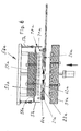
- a plant according to FIG. 1 comprises a device 1 for the manufacture of Moldings with a heater 50 and a transfer car for a cover layer.
- the transfer car consists primarily of one Tenter frame 60, which consists of two already connected Layers or two initially only alseinaderfruit layers existing cover layer 20 holds and carries.
- the cover layer 20 comprises a skin 21 on a serving as a carrier 22 foam.
- the Tenter frame 60 moves along rails 61 into the Heating device 50. He holds the cover layer 20 while in the Heating device 50 is heated and is located on the temperature control 54. Then, the tenter moves along the rails 61 around the heated cover layer 20 to be transported into the device 1.
- the heater 50 includes radiant heaters or a Infrared radiator arrangement 52, which is above the plane of the Tensioning frame 60 is arranged. It also includes a Tempering 54, which during the heating process in the plane of Tensioning frame 60 is arranged.
- the temperature control plate 54 is For example, a metal plate, which by means of liquid in channels (56) is heated so that the carrier (22) the desired temperature reached.
- the infrared radiator arrangement 52 and / or the temperature control plate 54 are each in the vertical direction to the plane of the clamping frame 60 moving towards and away from it, as indicated by double arrows is indicated. This is basically known, in Fig. 1 not illustrated devices such as hydraulic or pneumatic cylinders.
- the skin (21) of the cover layer (20) becomes such in the heater Heavily warmed that they doughy or viscous or even becomes molten.
- the degree of viscosity is dependent on the material selected such that a surface structure 21 'in a subsequent step pressed a or can be embossed and then fixed by cooling.
- the skin 21 is either on the serving as a carrier (22)
- Foam layer or a foam mat forms the bottom the skin 21.
- a material for the foam is for example a chemically crosslinked polyurethane. Through chemical crosslinking this material has almost duroplastic properties and is in able to withstand high temperatures, so that it even well above 200 ° C is resistant.
- Lying on the foam mat or together with the Foam mat is then made of polyethylene, for example existing skin 21 in an open, upper and lower mold existing device transported to deform.
- the device 1 comprises a molding tool 2 for forming a Front and a mold 3 for forming a back of a Product and in particular the cover layer 20 or one Molded part 40.
- the Forming tool 2 is a die-shaped upper mold, the one of Headstock or a support 4 is worn while the Forming tool 3 is a patrizeniano lower mold. Either one of Both or both molds 2 and 3 is / are in the vertical direction relatively movable, as shown schematically by double arrows is indicated.
- the relative movement between the forms can with any known Mechaninsmus are achieved, including hydraulic cylinders, pneumatic cylinders, mechanical drives such as spindle drives and counting like that.
- the mold 2 comprises an upper mold half 5 with a Surface 5 ', which is machined, polished and with a surface texture by engraving, etching or the like, as before has been described.
- This surface structure is on or several selected areas or on the whole of the Surface 5 'provided.
- the mold half 5 is preferably a solid steel mold extending easy to produce, process, polish and engrave or etch, and that by means of known shaping and Metalworking techniques.
- a steel mold offers a high Inherent strength, a long useful life and allows that Provide a wide range of different Surface structures in their surface 5 '.
- the upper Formhucc 5 be an electroplated zinc mold surface, which is faster and cheaper to produce (for example, for molding series with a smaller number of parts to be formed), but a shorter one usable life has.
- Such a galvanically produced zinc mold can by chemical etching or a machining process be perforated or made porous to a continuous Apply suction vacuum.
- the mold 2 includes a vacuum space or a Vacuum chamber 6 with at least one vacuum channel 7, which with a suitable vacuum source (not shown) is connected, the designed to generate a slight vacuum, for example from 0.1 bar below the atmospheric pressure.
- the vacuum channel 7 can also serve as a passive ventilation duct or it can Mold 2 optionally also a vent channel. 8 exhibit.
- a plurality of openings for generating a negative pressure comprises Vacuum holes 9, which extend through the upper mold half 5. They communicate with the vacuum chamber 6 and extend through the surface 5 '.
- Each of these vacuum holes 9 in one massive half-mold 5 'made of steel consists of a mechanical drilled hole section 9A and a laser drilled Bore portion 9B.
- the mechanically drilled hole portion 9A may be any one have a suitable diameter, for example 3 to 5 mm, while the laser drilled hole portion 9B has a very fine Diameter, for example less than 0.5 mm, or especially less than 0.3 mm, and in some cases about 0.2 mm.
- the diameter of the laser-drilled hole portion 9B is so selected that the molten skin material is hindered in this Vacuum holes 9 to flow or be sucked to the Formation of unwanted nodules and spots or other Defects on the finished surface of the molding too avoid.
- the vacuum holes 9 by chemical means with the required small diameter through the mold be formed or etched.
- the numerous vacuum holes 9 are distributed and arranged in a pattern, for example in Distances of 30 to 40 mm from each other across the whole relevant surface 5 ', on which a vacuum is applied to a uniform application of the vacuum and the vent and To ensure removal of any trapped exhaust air.
- the mold half 5 further includes cooling channels 10 through which a Tempering liquid such as water or oil can flow to the Mold half 5 to a constant and even temperature too temper, which is suitable, the molded part with appropriate Speed to cool and solidify, for example, a Mold temperature in the range of 45 to 60 ° C and especially about 50 ° C.
- the mold 3 comprises a second mold half 11 with a second surface 11 ', which is generally configured to be for upper mold half 5 fits, with a suitable gap (for example about 4 mm) therebetween, as described below.
- the molding tool 3 is provided with an air space or an air channel 12 provided, which is connected to an air line 13 and with air holes 14 in different planes or portions of its surface 11 ' empties.
- the L effet 13 can with a compressed air source for example, first 100 ° C hot air or with another pressure medium such as steam, another gas or liquid at a pressure of 1 to 30 in particular from 6 to 30 bar and especially from 5 to 20 bar, get connected.
- the air holes 14 may be mechanically drilled Holes of suitable diameter are formed and are over the Surface 11 'of the lower mold or the lower mold half 11 distributed to a uniform distribution of compressed air or the to ensure other pressure medium in the molding process.
- the air holes 14 can mechanically drilled sections and have laser drilled portions, as in the vacuum holes 9 in the upper mold half 5 and upper mold 5 is the case.
- the device may be in a first molding stage operated with a vacuum that passes through the upper mold half. 5 is applied, and with pressure passing through the lower mold half 11th is applied to two on opposite sides of a
- a surface structure In such a case is also the surface 11 'similar to the surface 5' with a Provided surface structure.
- the mold half 5 is also the mold half 11 with cooling channels 15 provided, through which a bath liquid are circulated can make the mold half 11 on a uniform and constant Temperature, for example, in the range of 45 ° to 60 ° C. lies.
- the device 1 further comprises a peripheral circumferential around the periphery Sealing frame 16, which is to achieve an airtight High pressure seal between the lower mold half 11 and the upper mold half 5 along its circumference serves to a under pressure To keep standing pressure medium in the mold gap, as follows is described.
- the Sealing frame 16 preferably elastically yielding to the Mold half 3 or mounted on the lower mold 3, so that he moves with this in the direction of the mold half 2, until a Sealing member 17 presses against the cover layer and seals (as it described below).
- an elastic suspension device 18 supplies like a spring pneumatic cylinder or the like, a desired force to the Seal member 17 firmly against the upper mold half 5 / upper mold to keep with the cover layer sandwiched between them.
- an elastic suspension device 18 supplies like a spring pneumatic cylinder or the like, a desired force to the Seal member 17 firmly against the upper mold half 5 / upper mold to keep with the cover layer sandwiched between them.
- the Sealing frame 16 may be formed so that the Clamping frame 60 receives or works with this to the to achieve required airtight seal.
- Fig. 1 shows an initial stage when operating the device 1.
- a cover layer 20 with a skin 21 and a support 22 has been incorporated in US Pat the heater 50 heated (as indicated by dashed lines is indicated) and then with means of the clamping frame 60 along a transported flat horizontal plane, namely along the rails 61, to be positioned between the mold half 5 and the mold half 11 become.
- the cover layer 20 is at their Peripheral edges by the tenter 60 (or any other known means, or the heated cover layer 20 can easily on the second mold half 11 are laid) worn and held.
- the skin 21 is a thermoplastic film
- the carrier 22 is a closed-cell or substantially closed-cell Polymer foam, preferably airtight over its thickness is.
- the cover layer 20 is a conventional known on the back foamed thermoplastic polyolefin (TPO) film.
- the skin 21 is preferably a polypropylene film or a Polyethylene film, however, may alternatively be a film Polyvinyl chloride act.
- the carrier 22 may be made of the same Polymer material such as the skin 21 (for example, polypropylene), however, in Foamed state exist or it can be a different Polymer material (for example, polyurethane), preferably has a higher melting point than that of the skin 21 (or none current melting temperature due to the cross connection).
- a preferred general combination is a fusible one thermoplastic skin 21 on a non-melting, thermoset or melting at higher temperature thermoplastic carrier 22.
- the cover layer 20 by means of a Heating device preheated, for example by means of the illustrated Infrared radiator assembly 52 to heat the skin 21 (For example, to about 200 ° C), while the carrier 22 on the Tempering plate 54 rests, so that the carrier is kept relatively cold (For example, below about 160 ° C or specifically to about 140 ° C or less), so that it does not melt.
- the cover layer 20 became heated so that the skin 21 reaches at least its melting temperature (and with enough residual heat so that it remains molten until it is formed in the subsequent step), while the carrier 22 a Temperature reached at which it is malleable, but the temperature is below the melting temperature of the carrier.
- the skin 21 was substantially or completely in one viscous state melted so that they are uniform on the Carrier 22 sticks and can be carried by him, his maintains firm, moldable foam state.
- the Carrier 22 does not soften to a state in which he is unable to Tension and support for the molten material of the skin 21 to offer.
- the cover layer 20 is preferably as shown oriented, with the skin 21 at the top of the one floor forming support 22 is arranged. The molten skin can therefore do not drip or drain from the carrier 22.
- the Mold half 11 moves upward and / or the mold half 2 down moved, so that the mold half 11 and its surface 11 ' the cover layer 20 relative to the surface 5 'of the mold half 5 in one shaped contour deformed, as shown in FIG. 2 substantially.
- the Form half 11 engages the slightly cooler, not melted Carrier 22 and performs a deep drawing step in a first operation out.
- the molten skin 21 is optionally already against the structured surface 5 'pressed.
- the Sealing frame 16 is pressed against the mold half 5 and forms a air-tight seal along the circumference of the cover layer 20.
- This deep drawing step allows the air passively out of the space between the cover layer 20 and the surface 5 'through the vacuum holes. 9 and escape through the vacuum channel 7 or the venting channel 8. It is not necessary, but optional, at this stage Apply vacuum through the vacuum channel 7. It is preferred in This stage still generates no vacuum to the energy consumption in the To reduce the rather large volume of air.
- the mold half 3 has upwards in a End position relative to the mold half 2 moves, with a defined Forming gap 23 between the surface 5 'and the surface 11' remains.
- This mold gap 23 is characterized by the circumferential Sealing frame 16 or another element secured as Stop for the movement of the mold half 11 relative to the mold half 5 acts.
- the mold gap 23 has a dual function and dimensions such that he is able to take the cover layer 20 and a Air gap 24 between the two surfaces 5 'and 11' to form.
- the air gap 24 is preferably sized (for example 4 mm), that it corresponds to the strength of the substratum, that in another Step is formed, as will be described later.
- the pressure medium presses uniformly against the carrier 22, and it is the final forming of the cover layer 20 against the surface 5 ' achieved by means of a purely pneumatic blow molding, preferably without direct mechanical mold contact between the surface 11 ' and the cover layer 20 in this process step.
- the result is a very uniform and contour-adapted shaping of the cover layer against the surface 5 ', which any tolerances or deviations or the like between the two forms.
- the carrier 22 is not (or substantially not) permeable to air, it acts as Buffer or intermediate layer and distributes the molding pressure uniformly the skin 21. The molten skin is evenly against the structured surface 5 'pressed and shaped.
- the negative pressure passing through the vacuum holes 9 can be applied, sure that no between the skin 21 and the surface 5 'enclosed air pockets remain, the Skin 21 firmly in a predetermined, aligned position opposite the surface 5 'is held.
- the supply of pressure medium through the air line 13 interrupted, while the application of negative pressure by the Vacuum channel 7 and the vacuum holes 9 preferably continued is to the molded cover layer 20 in a fixed position in the Shape half 5 to hold.
- the cooling and Solidification of the cover layer 20 continues.
- the device becomes 1 opened, including the mold half 11 down and / or the mold half. 5 is moved upward.
- the finished, molded and structured cover layer 20 taken and she can later in a separate procedure as cover skin on a desired Substrate or part are placed.
- the Cover layer 20 also by negative pressure on the mold half. 5 can be held, and a substrate 30 can directly on the back of the preformed cover layer 20 formed in the same device 1 become.
- This substrate material 30 is preferably a preheated layer from a composite material of polyolefin fibers, for example Polypropylene fibers and natural fibers or glass fibers or Polyester fibers or the like, or it may be a polyurethane foam be provided, which was preheated by known means and the worn by known means in the device or in her is arranged.
- the device 1 is closed, the Forming tool 3 for a back up and / or the Mold 2 was moved downward, so that the mold half 11 the Substrate 30 against the back of the carrier 22 of the previously formed Cover layer 20 presses and shapes.
- the sealing frame 16 keeps the airtight seal all around the perimeter of the molded Arrangement upright.
- the preheated and at least partially molten polyolefin fibers of the substrate 30 undergo a Melt bonding with the still warm or still hot carrier 22 the cover layer 20 so that the substrate 30 is integral with the cover layer 20 is connected without any intermediate adhesive or the like is required.
- the substrate 30 was mechanically in The required three-dimensional contoured configuration is shaped and deformed while the substrate material 30 now the part of the mold gap 23 occupies the previously the air gap 24 in the forming stage was as shown in FIG.
- the entire molding process with its Step sequences for forming and applying a surface structure the cover layer 20 and then the molding and lamination of the substrate 30 on the cover layer 20 with a single set of molds be performed in a single device 1, in two successive stages of formation, without any Realignment or repositioning of the molds or other Equipment is required and without the molded part for any required process step to another Device must be moved.
- FIG. 4 shows schematically the enlarged result the performed according to FIG. 2 first forming step.
- Fig. 5 shows an enlarged schematic Detail of the result from the implementation of the second Shaping stage according to FIG. 3.
- the cover layer 20 retains its Surface structure and contour, while a substrate material 30 on their back was molded and laminated.
- a Foaming polymer material by spraying, pouring, pouring or Injecting the material into the air gap 24 between the cover layer 20 and the mold half 11 to form the substrate 30.
- the substrate material 30 in the required three-dimensional contoured shape brought and shaped while it laminated at the same time and adhered to the support 22 of the cover layer 20 is brought.
- the print medium itself a foaming polymer resin in liquid form in the Forming gap is introduced, for example by injection corresponding injection channels in the mold stage of FIG. 2. This As a result, it combines the steps of FIGS. 2 and 3 into one single stage.
- foaming polymeric resin begins to foam and expanded, it generates a corresponding pressure and it works as a printing medium, the cover layer 20 against the surface 5 'in the Form stage of FIG. 2 expresses, as described above. Then, when the foaming polymer resin cools and hardens or hardens, wherein it is in contact with the tempered mold half 11th stands, it directly forms the substrate 30 as shown in Fig. 3. Accordingly, the foam backing allows the entire Forming process with a single opening and shooting cycle perform.
- the substrate 30 and the cover layer 20 on cooled and slightly solidified in the stage of FIG. 3, which is a Consequence of the contact with the mold half 5 and the mold half 11, the be tempered by means of cooling.
- the finished molding 40 which is shown schematically in Fig. 5th is shown removed from the mold after the vacuum application was interrupted by the vacuum channel 7.
- the molded cover layer 20 itself could be without the Substrate lamination shown in FIG. 3 are used. With others In words, the method after the completion of FIG. 2 considered complete.
- the shaped and textured top layer could be replaced with any a conventional substrate in a conventional manner combined or suitable Use cases "as is" used.
- another Cover layer formed on the opposite surface of the substrate 30 be, with this additional cover layer also with a Surface structure can be provided in their skin.
- the preheated additional Covering layer in the open mold between the substrate and the Lower mold or the lower mold half 11 introduced, the Surface 11 ' was also provided with a surface structure. Then the mold with a sufficiently larger mold gap opening closed, leaving room for the extra topcoat is.
- Compressed air is supplied to the vacuum holes 9, while a Vacuum is applied via the air holes 14 to substantially the initial shaping and the process of surface structuring perform according to Fig. 2, but with the functions of the upper Mold half and the other mold half are interchanged.
- This stage can be no blow molding in the extent as in reach first stage, however, the molded surface structure educated. In this way, a finished molding can be produced
- the structured surfaces of the respective skin are absorbed has opposite sides.
- FIG. 6-8 A modified form of the heater is shown in Figs. 6-8 shown. Basically the same parts have the same reference numbers and additionally the letter index a as in the heater 50 according to FIG. 1.
- the heating device 50a is also used to heat a cover layer 20a, the from a subsequently referred to as skin 21 a decorative layer and a second, serving as a carrier for the highly heated skin 21a Carrying layer exists.
- Characteristic of the heater 50a compared to the other Heating device 50 is an additionally provided protective hood 50 a, the ensures that the two-layer cover layer 20a when heated in a closed chamber 71a. The Heating zone is thus encapsulated during the heating process.
- Heating elements provided with different objectives. These are according to embodiment radiant heater and in particular Infrared radiator 53 a at one the chamber 71 a still up final ceiling element 55a on the one hand and a contact heater with a contact surface in the form of a tempering plate (54a) on the other hand. During the heating or heating step the touches Temperature control plate (54 a), the cover layer (20 a) from below.
- the Protective hood 70a comprises side walls 57a which are arranged on all sides can. Further, according to that shown in Fig. 7 Embodiment also still intermediate pieces 58 a provided, the free space between the side walls 57a and the ceiling element 55a bridge.
- the Intermediate pieces 58a rigid with the ceiling element 55a of Heating device 50a connected.
- the side walls 57a are relative to the Intermediate pieces 58a movable up and down. That's it possible to open and close the chamber 71a.
- the side walls 57a of the protective hood 70a are lowered until the Chamber 71a is closed.
- the chamber 71a then again opened, as shown in Fig. 6.
- Drive means 59 a provided, which are pneumatic or hydraulic drives can act.
- temperature sensor 62 a in the interior of the chamber 71 a. At least two temperature sensors 62a are between the Infrared radiators 53 a arranged and with the help of a not closer interested control capable, possibly different Radiators to throttle or to enhance their effect.
- the topcoat 20a consists of two layers 21a and 22a.
- the melting points of Materials of these two layers 21a and 22a are different.
- the one, As a decorative layer 21a serving position has a lower compared Melting point than the other, serving as a carrier 22a position.
- the temperature control plate 54 a is provided and ensures that the as a carrier 22a serving location on a sufficiently low Temperature is maintained during the heating process, so that they have a sufficient stability and strength to carry and transport the other layer 21a retains despite its heating and softening.
- the degree of softening of the serving as a skin or decorative layer layer 21a may be different according to the requirements. It must a thermoplastic compound with the carrier 22 a done and a Surface structuring or the like by a pressure and Embossing must always be possible. Both the as Decor layer serving layer 21 a and serving as a carrier layer 22a may be plastic films.
- the support layer 22a As a material for the support layer 22a, however, in particular a chemically crosslinked, closed-cell plastic foam. Either is its softening temperature is much higher than that of the strong heated decor layer 21a or the temperature control for the Carrier layer 22a in the heater 50a is selected such that the Carrier layer 22a maintains sufficient stability and strength to as a carrier for the softened, doughy, viscous or molten To serve skin 21a.
- the temperature control in the heater 50, 50a can therefore be such that the one layer 21, 21a to a temperature of 200 ° C. (about 200 ° C) and the other layer 22, 22a to a temperature of 100 ° C (about 100 ° C) is heated.
- the tempering plate 54, 54a has then preferably a temperature of about 80 ° C to 90 ° C.
- One Vacuum or negative pressure is in the device 1 only then applied, when the skin 21, 21a is sufficiently hardened to a To prevent slippage of the skin from the contour, and preferably takes place in a further step, the Schupressen with a Substrate of, for example, 200 ° C hot polypropylene natural fiber mixture.
- the foam has not only a function as Carrier material, but also as a bridge at the negative pressure in the Device 1. He helps to ensure that the skin is not in the laser drilled bore sections 9B is sucked.
- multilayer moldings and in particular interior trim parts for motor vehicles can be, with first a semi-finished / intermediate product by Deep drawing and backpressing with a flow medium, i. in particular with compressed air in a mold gap between two Mold halves can be produced and that so then on the Semifinished a substrate is applied by the fact that the mold gap is filled with the substrate material, so that the semifinished product for Production of the final product not removed from the mold halves must become.
Landscapes
- Engineering & Computer Science (AREA)
- Mechanical Engineering (AREA)
- Moulds For Moulding Plastics Or The Like (AREA)
- Blow-Moulding Or Thermoforming Of Plastics Or The Like (AREA)
- Casting Or Compression Moulding Of Plastics Or The Like (AREA)
- Shaping Of Tube Ends By Bending Or Straightening (AREA)
Priority Applications (1)
| Application Number | Priority Date | Filing Date | Title |
|---|---|---|---|
| EP08012435A EP1974893A2 (fr) | 2001-08-13 | 2002-08-08 | Apparareil pour thermoformer des pièces avec imprimees à la surface |
Applications Claiming Priority (2)
| Application Number | Priority Date | Filing Date | Title |
|---|---|---|---|
| US09/929,693 US6749794B2 (en) | 2001-08-13 | 2001-08-13 | Method and apparatus for molding components with molded-in surface texture |
| US929693 | 2001-08-13 |
Related Child Applications (2)
| Application Number | Title | Priority Date | Filing Date |
|---|---|---|---|
| EP08012435A Division-Into EP1974893A2 (fr) | 2001-08-13 | 2002-08-08 | Apparareil pour thermoformer des pièces avec imprimees à la surface |
| EP08012435A Division EP1974893A2 (fr) | 2001-08-13 | 2002-08-08 | Apparareil pour thermoformer des pièces avec imprimees à la surface |
Publications (3)
| Publication Number | Publication Date |
|---|---|
| EP1284182A2 true EP1284182A2 (fr) | 2003-02-19 |
| EP1284182A3 EP1284182A3 (fr) | 2003-04-09 |
| EP1284182B1 EP1284182B1 (fr) | 2014-11-26 |
Family
ID=25458294
Family Applications (2)
| Application Number | Title | Priority Date | Filing Date |
|---|---|---|---|
| EP02017847.1A Expired - Lifetime EP1284182B1 (fr) | 2001-08-13 | 2002-08-08 | Procédé pour thermoformer des pièces avec des structures à la surface |
| EP08012435A Withdrawn EP1974893A2 (fr) | 2001-08-13 | 2002-08-08 | Apparareil pour thermoformer des pièces avec imprimees à la surface |
Family Applications After (1)
| Application Number | Title | Priority Date | Filing Date |
|---|---|---|---|
| EP08012435A Withdrawn EP1974893A2 (fr) | 2001-08-13 | 2002-08-08 | Apparareil pour thermoformer des pièces avec imprimees à la surface |
Country Status (5)
| Country | Link |
|---|---|
| US (1) | US6749794B2 (fr) |
| EP (2) | EP1284182B1 (fr) |
| JP (1) | JP4371638B2 (fr) |
| KR (1) | KR20030015155A (fr) |
| ES (1) | ES2526800T3 (fr) |
Cited By (16)
| Publication number | Priority date | Publication date | Assignee | Title |
|---|---|---|---|---|
| WO2005009721A1 (fr) | 2003-07-22 | 2005-02-03 | Findlay Industries Deutschland Gmbh | Elements de garniture interieure pour vehicules automobiles presentant un profil de surface defini |
| EP1704979A1 (fr) * | 2005-03-22 | 2006-09-27 | ArvinMeritor GmbH | Moule de thermoformage ou de moussage in situ de feuilles et procédé de fabrication d'un element composite |
| DE102006022263A1 (de) * | 2006-05-11 | 2007-11-15 | Uhlmann Pac-Systeme Gmbh & Co. Kg | Heizstation |
| AT503268B1 (de) * | 2006-02-20 | 2008-07-15 | Greiner Perfoam Gmbh | Verfahren zur herstellung eines mehrlagigen bauteils |
| DE102007009384A1 (de) * | 2007-02-20 | 2008-08-21 | Faurecia Innenraum Systeme Gmbh | Verfahren zum Hinterspritzen einer Schaumfolie |
| DE102007046472A1 (de) * | 2007-09-28 | 2009-04-09 | Curt Niebling | Verfahren zur Herstellung eines tiefgezogenen Folienteils aus Polycarbonat oder aus Polymethylmethacrylat |
| EP2179836A1 (fr) * | 2008-10-24 | 2010-04-28 | Faurecia Innenraum Systeme GmbH | Peau de moulage et procédé destiné à sa fabrication |
| WO2015117799A1 (fr) * | 2014-02-10 | 2015-08-13 | Bayerische Motoren Werke Aktiengesellschaft | Procédé de production d'un élément composite et élément composite |
| CN105658395A (zh) * | 2013-10-31 | 2016-06-08 | 惠普发展公司,有限责任合伙企业 | 基底上带纹理的膜 |
| EP2644347A3 (fr) * | 2012-03-27 | 2016-07-13 | MBB Fertigungstechnik GmbH | Procédé destiné à fabriquer un élément en matière synthétique essentiellement en forme de coque renforcé en fibres |
| EP2660029A4 (fr) * | 2010-12-29 | 2016-11-02 | Lg Hausys Ltd | Moule sous vide comprenant un motif solide inverse et procédé de formation sous vide utilisant celui-ci |
| ES2615331A1 (es) * | 2015-12-03 | 2017-06-06 | Mecánica Y Tecnología Alimentaria, S.L. | Tapa para envases de producto dosificado en caliente y dispositivo para su fabricación |
| DE102006026063B4 (de) * | 2006-06-03 | 2020-02-27 | Kraussmaffei Technologies Gmbh | Verfahren zur Herstellung von beschichteten Verbund-Kunststoffformteilen und Spritzgießmaschine hierfür |
| DE102017222157B4 (de) | 2017-10-12 | 2021-09-30 | Hyundai Motor Company | Fahrzeuginnenraummaterialherstellungsvorrichtung und Verfahren zum Herstellen von Fahrzeuginnenraummaterial |
| DE102020134732A1 (de) | 2020-12-22 | 2022-06-23 | Liebherr-Hausgeräte Ochsenhausen GmbH | Thermoformteil |
| WO2024018496A1 (fr) * | 2022-07-20 | 2024-01-25 | Persico S.P.A. | Procédé de revêtement d'un substrat préformé |
Families Citing this family (97)
| Publication number | Priority date | Publication date | Assignee | Title |
|---|---|---|---|---|
| US6652273B2 (en) * | 2002-01-14 | 2003-11-25 | The Procter & Gamble Company | Apparatus and method for controlling the temperature of manufacturing equipment |
| EP1371476A1 (fr) * | 2002-02-15 | 2003-12-17 | R+S Technik GmbH | Appareil pour la fabrication de habillage intérieur pour véhicules |
| KR100499866B1 (ko) * | 2002-12-18 | 2005-07-07 | 한국과학기술원 | 요철모양의 금형을 이용한 mcp 제작 방법 및 장치 |
| DE10301712B4 (de) * | 2003-01-13 | 2004-11-04 | Sai Automotive Sal Gmbh | Verfahren zum Herstellen von hinterspritzten Kunststoffformteilen |
| US20040209123A1 (en) * | 2003-04-17 | 2004-10-21 | Bajorek Christopher H. | Method of fabricating a discrete track recording disk using a bilayer resist for metal lift-off |
| DE10328046A1 (de) * | 2003-06-23 | 2005-01-13 | Arvinmeritor Gmbh | Verfahren zum Herstellen eines Kunststoffverbundbauteils, insbesondere eines Karosserieanbauteils |
| US7922956B1 (en) * | 2003-11-05 | 2011-04-12 | Leon Plastics, Inc. | Vehicular trim component and cover with simulated stitch and/or seam thereon |
| US20050151282A1 (en) * | 2004-01-13 | 2005-07-14 | Harper Bruce M. | Workpiece handler and alignment assembly |
| US7686606B2 (en) * | 2004-01-20 | 2010-03-30 | Wd Media, Inc. | Imprint embossing alignment system |
| US7329114B2 (en) * | 2004-01-20 | 2008-02-12 | Komag, Inc. | Isothermal imprint embossing system |
| US20050183897A1 (en) * | 2004-02-24 | 2005-08-25 | Lear Corporation | Two-shot co-injected automotive interior trim assembly and method |
| NO323512B1 (no) * | 2004-04-07 | 2007-06-04 | Crescendo As | Stopeform for framstilling av en hjelmfôring. |
| US20060062970A1 (en) * | 2004-04-19 | 2006-03-23 | Martin James N | Embossed headliner and method of making same |
| EP1741543B1 (fr) * | 2004-04-30 | 2014-03-05 | Kyoraku Co., Ltd. | Panneau de finition interieure pour vehicule et son procede de fabrication |
| US7699595B2 (en) * | 2004-07-19 | 2010-04-20 | R + S Technik Gmbh | Method and apparatus for molding a laminated trim component without use of slip frame |
| US20060027036A1 (en) * | 2004-08-05 | 2006-02-09 | Biggs Todd L | Methods and apparatuses for imprinting substrates |
| US7478854B2 (en) * | 2004-10-19 | 2009-01-20 | International Automotive Components Group North America, Inc. | Automotive handle with soft feel and method of making the same |
| US20060082179A1 (en) * | 2004-10-19 | 2006-04-20 | Depue Todd L | Automotive trim assembly having impact countermeasures and method of making the same |
| US7156437B2 (en) * | 2004-10-19 | 2007-01-02 | Lear Corporation | Automotive trim part with applique and method of making same |
| US7458631B2 (en) * | 2004-10-19 | 2008-12-02 | International Automotive Components Group North America, Inc. | Automotive armrest with soft feel and method of making the same |
| US20060082175A1 (en) * | 2004-10-19 | 2006-04-20 | Cowelchuk Glenn A | Automotive trim part with multi-feel cover and method of making the same |
| US7458604B2 (en) * | 2004-10-20 | 2008-12-02 | International Automotive Components Group North America, Inc. | Automotive trim assembly having an integrated airbag door |
| US20060082109A1 (en) * | 2004-10-20 | 2006-04-20 | Hier Michael J | Method of making an automotive trim assembly having an integrated airbag door |
| US7108312B2 (en) * | 2004-11-09 | 2006-09-19 | Lear Corporation | Vehicle door trim bolster with multi-feel cover and method of making the same |
| US20060099395A1 (en) * | 2004-11-09 | 2006-05-11 | Cowelchuk Glenn A | Automotive interior trim assembly and method |
| US20060097544A1 (en) * | 2004-11-09 | 2006-05-11 | Cowelchuk Glenn A | Automotive interior trim assembly and method |
| US7192074B2 (en) * | 2004-11-10 | 2007-03-20 | Lear Corporation | Automotive compartment having an integrated spring mechanism and method of making the same |
| US7332207B2 (en) * | 2004-12-15 | 2008-02-19 | Visteon Global Technologies, Inc. | Component for a vehicle interior and a method of assembly |
| US20060151097A1 (en) * | 2005-01-13 | 2006-07-13 | Bennett Norman H | Method of making a non-carpeted floor covering |
| FR2880838B1 (fr) * | 2005-01-19 | 2009-03-13 | Visteon Global Tech Inc | Procede de fabrication d'un panneau composite avec une peau decorative et panneau correspondant |
| JP2007069355A (ja) * | 2005-09-02 | 2007-03-22 | Toyota Motor Corp | 成形金型 |
| US20070134485A1 (en) * | 2005-12-08 | 2007-06-14 | Collins Daniel J | Blow molded articles having capped or inserted thermoplastic vulcanizate foam surfaces |
| US20070202327A1 (en) * | 2005-12-19 | 2007-08-30 | Alberto Baban | Synthetic cork with a natural cork appearance and method of making it |
| KR100783617B1 (ko) * | 2006-05-18 | 2007-12-10 | 덕양산업 주식회사 | 미세발포 시트를 적용한 다층구조의 인스트루먼트 판넬 및 그 제조방법 |
| EP2098349B1 (fr) * | 2006-12-01 | 2018-10-03 | Tanazawa Hakkosha Co., Ltd. | Moule pour moulage de résine, procédé de fabrication de moule pour moulage de résine, et produit moulé à base de résine |
| KR100815497B1 (ko) | 2007-04-18 | 2008-03-20 | 한일이화주식회사 | 차량용 트렁크모듈 부품의 제조장치 및 방법 |
| WO2009070757A1 (fr) * | 2007-11-26 | 2009-06-04 | International Automotive Components Group North America, Inc. | Application de faux bois en 3d |
| JP5025549B2 (ja) | 2008-03-31 | 2012-09-12 | キョーラク株式会社 | 発泡ブロー成形品およびその製造方法 |
| US8012290B2 (en) * | 2008-06-30 | 2011-09-06 | Herbert Olbrich Gmbh & Co. Kg | Method and apparatus for producing a three-dimensionally molded, laminated article with transfer-printed surface decoration |
| CN101618597A (zh) * | 2008-07-04 | 2010-01-06 | 深圳富泰宏精密工业有限公司 | 吸塑模具及其抽气孔打孔装置 |
| JP5253103B2 (ja) * | 2008-11-17 | 2013-07-31 | 日産自動車株式会社 | 車両用内装部品 |
| DE102009031453A1 (de) * | 2009-07-02 | 2011-01-05 | Werner Beuerlein | Gussform mit Entlüfter |
| CN102112279A (zh) * | 2009-09-10 | 2011-06-29 | 乐金华奥斯株式会社 | 利用水压或蒸汽压的成型装置和方法 |
| ES2388554T3 (es) * | 2009-10-14 | 2012-10-16 | Abb Technology Ag | Actuador magnético biestable para un disyuntor de media tensión |
| US8402638B1 (en) | 2009-11-06 | 2013-03-26 | Wd Media, Inc. | Press system with embossing foil free to expand for nano-imprinting of recording media |
| US8496466B1 (en) | 2009-11-06 | 2013-07-30 | WD Media, LLC | Press system with interleaved embossing foil holders for nano-imprinting of recording media |
| US9330685B1 (en) | 2009-11-06 | 2016-05-03 | WD Media, LLC | Press system for nano-imprinting of recording media with a two step pressing method |
| US20110204611A1 (en) * | 2010-02-18 | 2011-08-25 | Daimler Trucks North America Llc | Fiber reinforced polymer frame rail |
| JP5619449B2 (ja) * | 2010-03-26 | 2014-11-05 | 株式会社浅野研究所 | 差圧成形装置、及び、差圧成形シート製造方法 |
| JP5349403B2 (ja) * | 2010-05-17 | 2013-11-20 | テクノポリマー株式会社 | 光照射成形装置及び方法 |
| US20120104659A1 (en) * | 2010-11-02 | 2012-05-03 | Honeywell International Inc. | Apparatus for pitch densification |
| US20120104641A1 (en) | 2010-11-02 | 2012-05-03 | Honeywell International Inc. | Apparatus for pitch densification |
| WO2012061768A2 (fr) * | 2010-11-05 | 2012-05-10 | Lightweight Labs, Llc | Système et procédé de traitement et de consolidation thermiques |
| US20120153528A1 (en) | 2010-12-17 | 2012-06-21 | Honeywell International Inc. | Apparatus for carbon fiber processing and pitch densification |
| FR2978948B1 (fr) * | 2011-08-09 | 2015-05-15 | Faurecia Interieur Ind | Procede de realisation d'un element de garnissage comprenant une zone de decor d'aspect particulier |
| JP6142120B2 (ja) * | 2012-01-11 | 2017-06-07 | Scivax株式会社 | 成形方法及び成形装置 |
| DE102012222000A1 (de) * | 2012-11-30 | 2014-06-05 | Hp Pelzer Holding Gmbh | Herstellung wenigstens zweilagiger Bauteile |
| EP2930006B1 (fr) * | 2012-12-06 | 2017-09-13 | Scivax Corporation | Dispositif ainsi que procédé de pressage au rouleau, et dispositif de gaufrage |
| ES2967531T3 (es) * | 2013-02-12 | 2024-04-30 | Fraunhofer Ges Forschung | Lámina de separación recubierta de silicona con una capacidad especial de embutición en vacío |
| CN105209233A (zh) * | 2013-03-15 | 2015-12-30 | 赫尔曼米勒有限公司 | 具有纹理化表面的颗粒泡沫部件 |
| US9821509B2 (en) * | 2013-07-29 | 2017-11-21 | Faurecia Innenraum Systeme Gmbh | Method and device for producing an interior covering part |
| TW201507814A (zh) * | 2013-08-16 | 2015-03-01 | San Fang Chemical Industry Co | 製造硏磨墊及硏磨裝置之方法 |
| EP2958733B1 (fr) | 2013-08-20 | 2017-01-11 | SABIC Global Technologies B.V. | Procédé de formation d'articles à partir d'une feuille en matière plastique |
| EP3032573B1 (fr) * | 2014-06-03 | 2018-10-10 | Scivax Corporation | Dispositif de mise sous pression du type à rouleaux, dispositif d'impression, et procédé de mise sous pression du type à rouleaux |
| CN104309104A (zh) * | 2014-08-26 | 2015-01-28 | 金兴汽车内饰股份有限公司 | 汽车仪表板表皮阴模真空成型工艺 |
| DE102014219396A1 (de) * | 2014-09-25 | 2016-03-31 | Adidas Ag | Herstellungsverfahren für eine äußere Schicht für ein Paneel eines Balls |
| CN104441587B (zh) * | 2014-12-05 | 2017-02-01 | 瑞安市博诚机械有限公司 | 一种塑料杯盖热成型机 |
| US9944526B2 (en) | 2015-05-13 | 2018-04-17 | Honeywell International Inc. | Carbon fiber preforms |
| US10302163B2 (en) | 2015-05-13 | 2019-05-28 | Honeywell International Inc. | Carbon-carbon composite component with antioxidant coating |
| US10131113B2 (en) | 2015-05-13 | 2018-11-20 | Honeywell International Inc. | Multilayered carbon-carbon composite |
| US10076856B2 (en) * | 2015-06-15 | 2018-09-18 | International Automotive Components Group North America, Inc. | Manufacture of an article having a decorative cover sheet overlying a substrate |
| US10035305B2 (en) | 2015-06-30 | 2018-07-31 | Honeywell International Inc. | Method of making carbon fiber preforms |
| US10737423B2 (en) * | 2015-08-28 | 2020-08-11 | The Boeing Company | Systems and methods for sealant injection molding |
| US10022890B2 (en) | 2015-09-15 | 2018-07-17 | Honeywell International Inc. | In situ carbonization of a resin to form a carbon-carbon composite |
| KR101771653B1 (ko) | 2015-11-19 | 2017-08-25 | 한국신발피혁연구원 | 솔리드 성형재료의 가변압 발포 성형방법 |
| US10300631B2 (en) | 2015-11-30 | 2019-05-28 | Honeywell International Inc. | Carbon fiber preforms |
| US10828822B2 (en) | 2016-08-04 | 2020-11-10 | The Boeing Company | Method for fabricating thermoplastic sandwich structural panel using thermoforming and compression molding |
| US10207434B2 (en) * | 2016-08-04 | 2019-02-19 | The Boeing Company | In-mold apparatus and method for decorative application |
| SE540754C2 (en) * | 2016-11-30 | 2018-10-30 | Ikea Supply Ag | Molding of fiber blanks into three-dimensional fiber block |
| KR20180064605A (ko) * | 2016-12-05 | 2018-06-15 | 삼성디스플레이 주식회사 | 레이저 가공용 워크 테이블 및 이의 동작 방법 |
| GB2561334B (en) * | 2017-02-23 | 2022-05-18 | Auxetic Performance Ltd | A method of fabricating a workpiece made of fibres and resin |
| DE102017103943A1 (de) * | 2017-02-24 | 2018-08-30 | Auria Solutions Uk I Ltd. | Verkleidungsteil für ein Kraftfahrzeug, Verfahren und Vorrichtung zu seiner Herstellung |
| CN107150426B (zh) * | 2017-06-30 | 2019-08-02 | 中山市程博工业产品设计有限公司 | 一种使用方便的汽车模具 |
| DE102017214376A1 (de) * | 2017-08-17 | 2019-02-21 | Bayerische Motoren Werke Aktiengesellschaft | Verdeckanordnung für ein Kraftfahrzeug |
| DE102017118960B4 (de) * | 2017-08-18 | 2019-07-11 | Werkzeugbau Siegfried Hofmann Gmbh | Schäumwerkzeug |
| US11351703B2 (en) * | 2018-05-30 | 2022-06-07 | The Boeing Company | Matched compression die apparatus |
| JP7396613B2 (ja) * | 2018-05-31 | 2023-12-12 | 地方独立行政法人東京都立産業技術研究センター | 積層造形装置、三次元形状造形物に対する加工方法、三次元形状造形物及び金型 |
| CA3109221A1 (fr) * | 2018-12-19 | 2020-06-25 | Spartan Mat Llc | Systeme de tapis de traction et son procede de fabrication |
| CN109435109A (zh) * | 2018-12-30 | 2019-03-08 | 大连銮艺精密模塑制造有限公司 | 塑料产品精密修整加工治具 |
| DE102019204821A1 (de) * | 2019-04-04 | 2020-10-08 | Multivac Sepp Haggenmüller Se & Co. Kg | Formeinsatz für eine Tiefziehverpackungsmaschine und Herstellungsverfahren |
| US11518160B2 (en) * | 2019-08-29 | 2022-12-06 | Inteva Products, Llc | Method for non-contact adhesive activation and wrapping of a decorative skin to a part having curved surfaces and a part formed by the method |
| US11040664B2 (en) * | 2019-09-09 | 2021-06-22 | Ford Global Technologies, Llc | Support member for vehicle center console lid |
| CN112372995A (zh) * | 2020-10-26 | 2021-02-19 | 东莞市中鼎塑料制品有限公司 | 一种tpu高低温膜复合布的加工方法 |
| IT202000027227A1 (it) * | 2020-11-13 | 2022-05-13 | Persico Spa | Processo di stampaggio di un prodotto composito per rivestimenti |
| CN113400549B (zh) * | 2021-05-30 | 2022-09-16 | 湖北三江航天江河化工科技有限公司 | 一种异形绝热套模压模具及其操作方法 |
| CN114851525A (zh) * | 2022-03-28 | 2022-08-05 | 南昌航空大学 | 一种pmi泡沫真空热吸成型设备及运行方式 |
| FR3135914A1 (fr) * | 2022-05-30 | 2023-12-01 | Faurecia Interieur Industrie | Procédé de texturisation et de thermoformage d’un film d’aspect de pièce d’habillage |
Family Cites Families (36)
| Publication number | Priority date | Publication date | Assignee | Title |
|---|---|---|---|---|
| US3676537A (en) * | 1965-11-18 | 1972-07-11 | Thomas W Winstead | Continuous method of extruding and thero-forming skin-covered foamed thermoplastic articles |
| US4036675A (en) * | 1974-06-24 | 1977-07-19 | Owens-Illinois, Inc. | Film-lined foam plastic receptacles and laminated materials and methods for making the same |
| US4167595A (en) * | 1975-01-08 | 1979-09-11 | Alkor Gesellschaft Mit Beschrankter Haftung Kunststoffverkauf | Method of printing on plastic foil |
| CH626388A5 (fr) * | 1976-12-31 | 1981-11-13 | Alkor Gmbh | |
| EP0016438B1 (fr) * | 1979-03-15 | 1984-06-20 | Alkor Gmbh Kunststoffe | Procédé de fabrication d'un substrat flogué |
| DE2910234C2 (de) * | 1979-03-15 | 1983-05-26 | Alkor GmbH Kunststoffverkauf, 8000 München | Verfahren zur Herstellung eines Formkörpers aus einer Trägerplatte mit einer Dekorschicht |
| US4751141A (en) * | 1981-01-12 | 1988-06-14 | Alkor Gmbh Kunststoffverkauf | Process for the manufacture and use of a polypropylene foil with improved adhesion |
| JPS59232818A (ja) * | 1983-06-16 | 1984-12-27 | Tokyo Seat Kk | 圧空金型成形方法 |
| DE3429523A1 (de) * | 1984-08-10 | 1986-02-20 | Alkor GmbH Kunststoffe, 8000 München | Schaumlaminatfolie oder -bahn |
| US4921561A (en) * | 1984-10-18 | 1990-05-01 | Honda Giken Kogyo Kabushiki Kaisha | Process for manufacturing embossed articles of synthetic resin |
| DE3678646D1 (de) * | 1985-08-24 | 1991-05-16 | Alkor Gmbh | Folie oder folienbahn fuer moebel. |
| US4740417A (en) * | 1986-07-22 | 1988-04-26 | Cone Mills Corporation | Thermoplastic vacuum molding method and article produced thereby |
| DE3714365A1 (de) | 1987-04-30 | 1988-11-17 | Alkor Gmbh | Verfahren und vorrichtung zur herstellung von formteilen oder gegenstaenden aus thermoverformbaren kunststoffolien |
| DE3714367A1 (de) | 1987-04-30 | 1988-11-10 | Alkor Gmbh | Verfahren und vorrichtung zur herstellung von formteilen oder gegenstaenden aus thermoverformbaren kunststoffbahnen |
| DE3714366A1 (de) | 1987-04-30 | 1988-11-10 | Alkor Gmbh | Verfahren zur herstellung von formteilen oder gegenstaenden aus thermoverformbaren kunststoffolien, thermoverformbaren kunststoffhaltigen bahnen oder kunststoffplatten |
| DE8706204U1 (fr) | 1987-04-30 | 1988-09-01 | Alkor Gmbh Kunststoffe, 8000 Muenchen, De | |
| DE3723021A1 (de) | 1987-07-11 | 1989-01-19 | Alkor Gmbh | Verfahren und vorrichtung zur herstellung von formteilen oder gegenstaenden |
| DE8709582U1 (fr) | 1987-07-11 | 1988-11-10 | Alkor Gmbh Kunststoffe, 8000 Muenchen, De | |
| DE3834608A1 (de) | 1988-10-11 | 1990-04-19 | Alkor Gmbh | Verfahren zur herstellung von formteilen oder gegenstaenden fuer kraftfahrzeuge oder kraftfahrzeuginnenverkleidungen |
| DE3834607C2 (de) | 1988-10-11 | 1997-12-11 | Alkor Gmbh | Verfahren zur Herstellung von Gegenständen aus thermoverformbaren Kunststoffolien |
| DE3834648A1 (de) | 1988-10-11 | 1990-04-19 | Alkor Gmbh | Verfahren und vorrichtung zur herstellung von formteilen oder gegenstaenden fuer kraftfahrzeuge |
| DE3834620A1 (de) | 1988-10-11 | 1990-04-12 | Alkor Gmbh | Verfahren und vorrichtung sowie kunststoffolienbahn zur herstellung von formteilen oder gegenstaenden |
| DE4007877C2 (de) | 1990-03-13 | 1998-02-26 | Alkor Gmbh | Verfahren zur Herstellung von geprägten, narbstabilen, thermoverformbaren, vorzugsweise tiefziehfähigen Kunststoffolien |
| DE4007876C2 (de) | 1990-03-13 | 1998-02-12 | Alkor Gmbh | Verfahren zur Herstellung von geprägten, narbstabilen, thermoverformbaren, tiefziehfähigen Kunststoffolien |
| DE4010441C2 (de) | 1990-03-31 | 1994-10-20 | Roeder & Spengler Stanz | Vorrichtung zum Herstellen eines Formteils aus einem verformbaren Werkstück |
| DE4030477C2 (de) | 1990-09-26 | 1999-12-02 | Alkor Gmbh | Verfahren und Vorrichtung zur Herstellung von Formteilen oder Gegenständen |
| US5702810A (en) * | 1992-03-10 | 1997-12-30 | Mitsubishi Chemical Corporation | Cushioning composite molded article and a process for production thereof |
| EP0630746B1 (fr) * | 1993-06-21 | 1997-07-23 | Alkor Gmbh Kunststoffe | Film emboutissable, procédé pour sa fabrication et son utilisation |
| DE19530757A1 (de) * | 1995-08-22 | 1997-02-27 | Alkor Gmbh | Verfahren und Vorrichtung zur Herstellung von zwei- oder mehrfarbigen Schalttafelfolien, Armaturenbrettfolien oder daraus hergestellte Armaturenbretter für Kraftfahrzeuge |
| US5913996A (en) * | 1996-05-28 | 1999-06-22 | Tokyo Seat Co., Ltd. | Method of and apparatus for fabricating interior element for automotive vehicle |
| US5976289A (en) * | 1996-12-13 | 1999-11-02 | Toyo Tire & Rubber Co., Ltd. | Method of fabricating instrument panel |
| US5976288A (en) * | 1997-01-10 | 1999-11-02 | Ekendahl; Lars O. | Method of forming a molded, multi-layer structure |
| US6136415A (en) | 1997-05-27 | 2000-10-24 | R + S Technik Gmbh | Vehicle interior trim panel with a soft-touch foam layer, and a method and apparatus for making the same |
| US5863064A (en) * | 1997-08-14 | 1999-01-26 | Textron Autmotive Company Inc. | Skin for automotive air bag cover panel formed by casting different plastic materials |
| US6333094B1 (en) * | 1998-09-19 | 2001-12-25 | Alkor Gmbh Kunststoffe | Multilayer thermoformable composite synthetic veneer film for furniture and process for producing same |
| DE19959654A1 (de) | 1999-12-10 | 2001-06-21 | Findlay Ind Deutschland Gmbh | Verfahren zur Herstellung von Innenausstattungskomponenten von Kraftfahrzeugen |
-
2001
- 2001-08-13 US US09/929,693 patent/US6749794B2/en not_active Expired - Lifetime
-
2002
- 2002-08-08 EP EP02017847.1A patent/EP1284182B1/fr not_active Expired - Lifetime
- 2002-08-08 ES ES02017847.1T patent/ES2526800T3/es not_active Expired - Lifetime
- 2002-08-08 EP EP08012435A patent/EP1974893A2/fr not_active Withdrawn
- 2002-08-12 JP JP2002234766A patent/JP4371638B2/ja not_active Expired - Fee Related
- 2002-08-13 KR KR1020020047934A patent/KR20030015155A/ko not_active Application Discontinuation
Non-Patent Citations (1)
| Title |
|---|
| None |
Cited By (25)
| Publication number | Priority date | Publication date | Assignee | Title |
|---|---|---|---|---|
| EP1646492B2 (fr) † | 2003-07-22 | 2018-01-17 | Toyota Boshoku Kabushiki Kaisha | Elements de garniture interieure pour vehicules automobiles presentant un profil de surface defini |
| WO2005009721A1 (fr) | 2003-07-22 | 2005-02-03 | Findlay Industries Deutschland Gmbh | Elements de garniture interieure pour vehicules automobiles presentant un profil de surface defini |
| EP1704979A1 (fr) * | 2005-03-22 | 2006-09-27 | ArvinMeritor GmbH | Moule de thermoformage ou de moussage in situ de feuilles et procédé de fabrication d'un element composite |
| AT503268B1 (de) * | 2006-02-20 | 2008-07-15 | Greiner Perfoam Gmbh | Verfahren zur herstellung eines mehrlagigen bauteils |
| DE102006022263A1 (de) * | 2006-05-11 | 2007-11-15 | Uhlmann Pac-Systeme Gmbh & Co. Kg | Heizstation |
| DE102006022263B4 (de) * | 2006-05-11 | 2008-04-03 | Uhlmann Pac-Systeme Gmbh & Co. Kg | Heizstation |
| DE102006026063B4 (de) * | 2006-06-03 | 2020-02-27 | Kraussmaffei Technologies Gmbh | Verfahren zur Herstellung von beschichteten Verbund-Kunststoffformteilen und Spritzgießmaschine hierfür |
| WO2008101739A2 (fr) * | 2007-02-20 | 2008-08-28 | Faurecia Innenraum Systeme Gmbh | Procédé et moule pour produire un élément grainé |
| DE102007009384B4 (de) * | 2007-02-20 | 2020-11-26 | Faurecia Innenraum Systeme Gmbh | Verfahren zum Hinterspritzen einer Folie |
| DE102007009384A1 (de) * | 2007-02-20 | 2008-08-21 | Faurecia Innenraum Systeme Gmbh | Verfahren zum Hinterspritzen einer Schaumfolie |
| WO2008101739A3 (fr) * | 2007-02-20 | 2008-12-11 | Faurecia Innenraum Sys Gmbh | Procédé et moule pour produire un élément grainé |
| DE102007046472A1 (de) * | 2007-09-28 | 2009-04-09 | Curt Niebling | Verfahren zur Herstellung eines tiefgezogenen Folienteils aus Polycarbonat oder aus Polymethylmethacrylat |
| DE102007046472B4 (de) * | 2007-09-28 | 2013-12-24 | Bayer Materialscience Aktiengesellschaft | Verfahren zur Herstellung eines tiefgezogenen Folienteils aus Polycarbonat oder aus Polymethylmethacrylat |
| EP2179836A1 (fr) * | 2008-10-24 | 2010-04-28 | Faurecia Innenraum Systeme GmbH | Peau de moulage et procédé destiné à sa fabrication |
| EP2660029A4 (fr) * | 2010-12-29 | 2016-11-02 | Lg Hausys Ltd | Moule sous vide comprenant un motif solide inverse et procédé de formation sous vide utilisant celui-ci |
| RU2641135C2 (ru) * | 2012-03-27 | 2018-01-16 | МББ Фертигунгстехник ГмбХ | Способ изготовления по существу чашевидной детали из стеклопластика |
| EP2644347A3 (fr) * | 2012-03-27 | 2016-07-13 | MBB Fertigungstechnik GmbH | Procédé destiné à fabriquer un élément en matière synthétique essentiellement en forme de coque renforcé en fibres |
| CN105658395A (zh) * | 2013-10-31 | 2016-06-08 | 惠普发展公司,有限责任合伙企业 | 基底上带纹理的膜 |
| US10773463B2 (en) | 2014-02-10 | 2020-09-15 | Bayerische Motoren Werke Aktiengesellschaft | Method for producing a composite part, and composite part |
| WO2015117799A1 (fr) * | 2014-02-10 | 2015-08-13 | Bayerische Motoren Werke Aktiengesellschaft | Procédé de production d'un élément composite et élément composite |
| ES2615331A1 (es) * | 2015-12-03 | 2017-06-06 | Mecánica Y Tecnología Alimentaria, S.L. | Tapa para envases de producto dosificado en caliente y dispositivo para su fabricación |
| DE102017222157B4 (de) | 2017-10-12 | 2021-09-30 | Hyundai Motor Company | Fahrzeuginnenraummaterialherstellungsvorrichtung und Verfahren zum Herstellen von Fahrzeuginnenraummaterial |
| US11389993B2 (en) | 2017-10-12 | 2022-07-19 | Hyundai Motor Company | Vehicle interior material manufacturing apparatus and method for manufacturing vehicle interior material |
| DE102020134732A1 (de) | 2020-12-22 | 2022-06-23 | Liebherr-Hausgeräte Ochsenhausen GmbH | Thermoformteil |
| WO2024018496A1 (fr) * | 2022-07-20 | 2024-01-25 | Persico S.P.A. | Procédé de revêtement d'un substrat préformé |
Also Published As
| Publication number | Publication date |
|---|---|
| US6749794B2 (en) | 2004-06-15 |
| KR20030015155A (ko) | 2003-02-20 |
| EP1284182A3 (fr) | 2003-04-09 |
| EP1284182B1 (fr) | 2014-11-26 |
| JP4371638B2 (ja) | 2009-11-25 |
| JP2003117992A (ja) | 2003-04-23 |
| ES2526800T3 (es) | 2015-01-15 |
| US20030030188A1 (en) | 2003-02-13 |
| EP1974893A2 (fr) | 2008-10-01 |
Similar Documents
| Publication | Publication Date | Title |
|---|---|---|
| EP1284182B1 (fr) | Procédé pour thermoformer des pièces avec des structures à la surface | |
| DE69833439T2 (de) | Verfahren und gerät zum herstellen eines geformten gegenstandes | |
| DE3742457A1 (de) | Herstellverfahren fuer kunststoff-formteile mit dekorativ-gepraegter oberflaechenbeschichtung | |
| EP1287961A2 (fr) | Elément de revêtement ainsi que procédé et dispositif de fabrication d'un élément de revêtement multicouche | |
| EP0951984A1 (fr) | Procédé et dispositif pour la fabrication de pièces multicouches | |
| DE3840542C1 (en) | Process for producing a thin-walled, thermoformed plastic moulding and its use | |
| DE3607647A1 (de) | Verfahren zum kaschieren von formteilen und vorrichtung zu seiner durchfuehrung | |
| DE102017103943A1 (de) | Verkleidungsteil für ein Kraftfahrzeug, Verfahren und Vorrichtung zu seiner Herstellung | |
| DE102006024263A1 (de) | Kunststoffformteil mit einer dekorativen thermoplastischen Schicht | |
| DE4337697C1 (de) | Verfahren zur Herstellung von formstabilen, kaschierten Formteilen, wie Innenverkleidungen von Kraftfahrzeugen | |
| DE60025973T2 (de) | Formteil sowie Verfahren zu seiner Herstellung | |
| EP1235679B1 (fr) | Procede de fabrication de composants d'equipement interieur de vehicules motorises et produit correspondant | |
| WO2010051866A1 (fr) | Procédé et dispositif de fabrication d'une pièce de forme avec surface décorée | |
| EP0543085A1 (fr) | Procédé et dispositif pour fabriquer des objets moulés stratifiés | |
| DE60217249T2 (de) | Verfahren zum Herstellen von pressgeformten Gegenständen | |
| WO2008101739A2 (fr) | Procédé et moule pour produire un élément grainé | |
| DE102010049652B4 (de) | Verbundteil und Verfahren zur Herstellung eines Verbundteils | |
| DE102008037131B4 (de) | Vorrichtung zum Herstellen eines formstabilen, sichtbaren Verkleidungsteils für ein Kraftfahrzeug sowie form- und narbgebende Schale zum lösbaren Verbinden mit einer Werkzeughälfte einer Spritzgießmaschine | |
| DE3108571C2 (de) | Verfahren zum Herstellen eines aus einem Träger und aus einer auf dem Träger angeordneten Deckschicht bestehenden Verbundkörpers sowie Vorrichtung zur Durchführung des Verfahrens | |
| EP1147875A2 (fr) | Procédé pour recouvrir la surface profilée d'une pièce support devant être revêtue avec un matériau décoratif | |
| EP0914934B1 (fr) | Procédé et dispositif pour l'emboutissage de matières | |
| DE3844584A1 (de) | Verfahren zur herstellung eines duennwandigen, tiefgezogenen kunststoff-formteils und das erhaltene kunststoff-formteil | |
| DE102004019293A1 (de) | Verfahren zur Formung von Kunstoffplatten | |
| DE102018212610A1 (de) | Verfahren zur Herstellung eines mehrschichtigen Kunststoffbauteils | |
| DE102005001099B4 (de) | Verfahren und Vorrichtung zur Herstellung einer thermogeformten und mit einer Oberflächennarbung versehenen Kunststofffolie |
Legal Events
| Date | Code | Title | Description |
|---|---|---|---|
| PUAI | Public reference made under article 153(3) epc to a published international application that has entered the european phase |
Free format text: ORIGINAL CODE: 0009012 |
|
| AK | Designated contracting states |
Designated state(s): AT BE BG CH CY CZ DE DK EE ES FI FR GB GR IE IT LI LU MC NL PT SE SK TR |
|
| AX | Request for extension of the european patent |
Extension state: AL LT LV MK RO SI |
|
| PUAL | Search report despatched |
Free format text: ORIGINAL CODE: 0009013 |
|
| 17P | Request for examination filed |
Effective date: 20030110 |
|
| AK | Designated contracting states |
Kind code of ref document: A3 Designated state(s): AT BE BG CH CY CZ DE DK EE ES FI FR GB GR IE IT LI LU MC NL PT SE SK TR |
|
| AX | Request for extension of the european patent |
Extension state: AL LT LV MK RO SI |
|
| AKX | Designation fees paid |
Designated state(s): AT BE BG CH CY CZ DE DK EE ES FI FR GB GR IE IT LI LU MC NL PT SE SK TR |
|
| 17Q | First examination report despatched |
Effective date: 20040114 |
|
| RAP1 | Party data changed (applicant data changed or rights of an application transferred) |
Owner name: HERBERT OLBRICH GMBH & CO. KG |
|
| RAP1 | Party data changed (applicant data changed or rights of an application transferred) |
Owner name: OLBRICH GMBH |
|
| RIC1 | Information provided on ipc code assigned before grant |
Ipc: B29C 51/42 20060101ALI20140120BHEP Ipc: B29C 43/36 20060101ALI20140120BHEP Ipc: B29C 59/02 20060101ALI20140120BHEP Ipc: B29C 43/18 20060101AFI20140120BHEP Ipc: B29L 9/00 20060101ALN20140120BHEP Ipc: B29C 51/14 20060101ALI20140120BHEP Ipc: B29L 31/30 20060101ALN20140120BHEP Ipc: B29C 37/00 20060101ALI20140120BHEP |
|
| RIC1 | Information provided on ipc code assigned before grant |
Ipc: B29C 43/18 20060101AFI20140203BHEP Ipc: B29L 31/30 20060101ALN20140203BHEP Ipc: B29C 51/14 20060101ALI20140203BHEP Ipc: B29C 43/36 20060101ALI20140203BHEP Ipc: B29C 51/42 20060101ALI20140203BHEP Ipc: B29L 9/00 20060101ALN20140203BHEP Ipc: B29C 59/02 20060101ALI20140203BHEP Ipc: B29C 37/00 20060101ALI20140203BHEP |
|
| GRAP | Despatch of communication of intention to grant a patent |
Free format text: ORIGINAL CODE: EPIDOSNIGR1 |
|
| INTG | Intention to grant announced |
Effective date: 20140429 |
|
| RIC1 | Information provided on ipc code assigned before grant |
Ipc: B29C 43/36 20060101ALI20140417BHEP Ipc: B29C 37/00 20060101ALI20140417BHEP Ipc: B29L 9/00 20060101ALN20140417BHEP Ipc: B29C 59/02 20060101ALI20140417BHEP Ipc: B29L 31/30 20060101ALN20140417BHEP Ipc: B29C 51/14 20060101ALI20140417BHEP Ipc: B29C 51/42 20060101ALI20140417BHEP Ipc: B29C 43/18 20060101AFI20140417BHEP |
|
| REG | Reference to a national code |
Ref country code: DE Ref legal event code: R079 Ref document number: 50215997 Country of ref document: DE Free format text: PREVIOUS MAIN CLASS: B29C0059020000 Ipc: B29C0043180000 |
|
| GRAP | Despatch of communication of intention to grant a patent |
Free format text: ORIGINAL CODE: EPIDOSNIGR1 |
|
| RIC1 | Information provided on ipc code assigned before grant |
Ipc: B29C 37/00 20060101ALI20140528BHEP Ipc: B29L 9/00 20060101ALN20140528BHEP Ipc: B29L 31/30 20060101ALN20140528BHEP Ipc: B29C 43/18 20060101AFI20140528BHEP Ipc: B29C 51/14 20060101ALI20140528BHEP Ipc: B29C 43/36 20060101ALI20140528BHEP Ipc: B29C 59/02 20060101ALI20140528BHEP Ipc: B29C 51/42 20060101ALI20140528BHEP |
|
| RIN1 | Information on inventor provided before grant (corrected) |
Inventor name: SPENGLER, ERNST MAXIMILIAN |
|
| INTG | Intention to grant announced |
Effective date: 20140613 |
|
| GRAS | Grant fee paid |
Free format text: ORIGINAL CODE: EPIDOSNIGR3 |
|
| GRAA | (expected) grant |
Free format text: ORIGINAL CODE: 0009210 |
|
| AK | Designated contracting states |
Kind code of ref document: B1 Designated state(s): AT BE BG CH CY CZ DE DK EE ES FI FR GB GR IE IT LI LU MC NL PT SE SK TR |
|
| REG | Reference to a national code |
Ref country code: GB Ref legal event code: FG4D Free format text: NOT ENGLISH |
|
| REG | Reference to a national code |
Ref country code: CH Ref legal event code: EP |
|
| REG | Reference to a national code |
Ref country code: GB Ref legal event code: 746 Effective date: 20141119 |
|
| REG | Reference to a national code |
Ref country code: AT Ref legal event code: REF Ref document number: 697914 Country of ref document: AT Kind code of ref document: T Effective date: 20141215 |
|
| REG | Reference to a national code |
Ref country code: IE Ref legal event code: FG4D Free format text: LANGUAGE OF EP DOCUMENT: GERMAN |
|
| REG | Reference to a national code |
Ref country code: DE Ref legal event code: R096 Ref document number: 50215997 Country of ref document: DE Effective date: 20150108 |
|
| REG | Reference to a national code |
Ref country code: ES Ref legal event code: FG2A Ref document number: 2526800 Country of ref document: ES Kind code of ref document: T3 Effective date: 20150115 |
|
| REG | Reference to a national code |
Ref country code: ES Ref legal event code: GC2A Effective date: 20150121 |
|
| REG | Reference to a national code |
Ref country code: DE Ref legal event code: R084 Ref document number: 50215997 Country of ref document: DE |
|
| REG | Reference to a national code |
Ref country code: NL Ref legal event code: VDEP Effective date: 20141126 |
|
| REG | Reference to a national code |
Ref country code: DE Ref legal event code: R084 Ref document number: 50215997 Country of ref document: DE Effective date: 20150302 |
|
| PG25 | Lapsed in a contracting state [announced via postgrant information from national office to epo] |
Ref country code: FI Free format text: LAPSE BECAUSE OF FAILURE TO SUBMIT A TRANSLATION OF THE DESCRIPTION OR TO PAY THE FEE WITHIN THE PRESCRIBED TIME-LIMIT Effective date: 20141126 Ref country code: PT Free format text: LAPSE BECAUSE OF FAILURE TO SUBMIT A TRANSLATION OF THE DESCRIPTION OR TO PAY THE FEE WITHIN THE PRESCRIBED TIME-LIMIT Effective date: 20150326 Ref country code: NL Free format text: LAPSE BECAUSE OF FAILURE TO SUBMIT A TRANSLATION OF THE DESCRIPTION OR TO PAY THE FEE WITHIN THE PRESCRIBED TIME-LIMIT Effective date: 20141126 |
|
| PG25 | Lapsed in a contracting state [announced via postgrant information from national office to epo] |
Ref country code: GR Free format text: LAPSE BECAUSE OF FAILURE TO SUBMIT A TRANSLATION OF THE DESCRIPTION OR TO PAY THE FEE WITHIN THE PRESCRIBED TIME-LIMIT Effective date: 20150227 Ref country code: CY Free format text: LAPSE BECAUSE OF FAILURE TO SUBMIT A TRANSLATION OF THE DESCRIPTION OR TO PAY THE FEE WITHIN THE PRESCRIBED TIME-LIMIT Effective date: 20141126 Ref country code: SE Free format text: LAPSE BECAUSE OF FAILURE TO SUBMIT A TRANSLATION OF THE DESCRIPTION OR TO PAY THE FEE WITHIN THE PRESCRIBED TIME-LIMIT Effective date: 20141126 |
|
| PG25 | Lapsed in a contracting state [announced via postgrant information from national office to epo] |
Ref country code: DK Free format text: LAPSE BECAUSE OF FAILURE TO SUBMIT A TRANSLATION OF THE DESCRIPTION OR TO PAY THE FEE WITHIN THE PRESCRIBED TIME-LIMIT Effective date: 20141126 Ref country code: EE Free format text: LAPSE BECAUSE OF FAILURE TO SUBMIT A TRANSLATION OF THE DESCRIPTION OR TO PAY THE FEE WITHIN THE PRESCRIBED TIME-LIMIT Effective date: 20141126 Ref country code: CZ Free format text: LAPSE BECAUSE OF FAILURE TO SUBMIT A TRANSLATION OF THE DESCRIPTION OR TO PAY THE FEE WITHIN THE PRESCRIBED TIME-LIMIT Effective date: 20141126 Ref country code: SK Free format text: LAPSE BECAUSE OF FAILURE TO SUBMIT A TRANSLATION OF THE DESCRIPTION OR TO PAY THE FEE WITHIN THE PRESCRIBED TIME-LIMIT Effective date: 20141126 |
|
| REG | Reference to a national code |
Ref country code: FR Ref legal event code: PLFP Year of fee payment: 14 |
|
| REG | Reference to a national code |
Ref country code: DE Ref legal event code: R097 Ref document number: 50215997 Country of ref document: DE |
|
| PLBE | No opposition filed within time limit |
Free format text: ORIGINAL CODE: 0009261 |
|
| STAA | Information on the status of an ep patent application or granted ep patent |
Free format text: STATUS: NO OPPOSITION FILED WITHIN TIME LIMIT |
|
| PGFP | Annual fee paid to national office [announced via postgrant information from national office to epo] |
Ref country code: GB Payment date: 20150824 Year of fee payment: 14 |
|
| 26N | No opposition filed |
Effective date: 20150827 |
|
| PGFP | Annual fee paid to national office [announced via postgrant information from national office to epo] |
Ref country code: IT Payment date: 20150831 Year of fee payment: 14 |
|
| PG25 | Lapsed in a contracting state [announced via postgrant information from national office to epo] |
Ref country code: MC Free format text: LAPSE BECAUSE OF FAILURE TO SUBMIT A TRANSLATION OF THE DESCRIPTION OR TO PAY THE FEE WITHIN THE PRESCRIBED TIME-LIMIT Effective date: 20141126 Ref country code: LU Free format text: LAPSE BECAUSE OF FAILURE TO SUBMIT A TRANSLATION OF THE DESCRIPTION OR TO PAY THE FEE WITHIN THE PRESCRIBED TIME-LIMIT Effective date: 20150808 |
|
| REG | Reference to a national code |
Ref country code: CH Ref legal event code: PL |
|
| PG25 | Lapsed in a contracting state [announced via postgrant information from national office to epo] |
Ref country code: CH Free format text: LAPSE BECAUSE OF NON-PAYMENT OF DUE FEES Effective date: 20150831 Ref country code: LI Free format text: LAPSE BECAUSE OF NON-PAYMENT OF DUE FEES Effective date: 20150831 |
|
| REG | Reference to a national code |
Ref country code: IE Ref legal event code: MM4A |
|
| PG25 | Lapsed in a contracting state [announced via postgrant information from national office to epo] |
Ref country code: IE Free format text: LAPSE BECAUSE OF NON-PAYMENT OF DUE FEES Effective date: 20150808 |
|
| REG | Reference to a national code |
Ref country code: FR Ref legal event code: PLFP Year of fee payment: 15 |
|
| REG | Reference to a national code |
Ref country code: AT Ref legal event code: MM01 Ref document number: 697914 Country of ref document: AT Kind code of ref document: T Effective date: 20150808 |
|
| PG25 | Lapsed in a contracting state [announced via postgrant information from national office to epo] |
Ref country code: AT Free format text: LAPSE BECAUSE OF NON-PAYMENT OF DUE FEES Effective date: 20150808 |
|
| GBPC | Gb: european patent ceased through non-payment of renewal fee |
Effective date: 20160808 |
|
| PG25 | Lapsed in a contracting state [announced via postgrant information from national office to epo] |
Ref country code: BG Free format text: LAPSE BECAUSE OF FAILURE TO SUBMIT A TRANSLATION OF THE DESCRIPTION OR TO PAY THE FEE WITHIN THE PRESCRIBED TIME-LIMIT Effective date: 20141126 |
|
| PG25 | Lapsed in a contracting state [announced via postgrant information from national office to epo] |
Ref country code: GB Free format text: LAPSE BECAUSE OF NON-PAYMENT OF DUE FEES Effective date: 20160808 Ref country code: BE Free format text: LAPSE BECAUSE OF NON-PAYMENT OF DUE FEES Effective date: 20150831 |
|
| REG | Reference to a national code |
Ref country code: FR Ref legal event code: PLFP Year of fee payment: 16 |
|
| PG25 | Lapsed in a contracting state [announced via postgrant information from national office to epo] |
Ref country code: TR Free format text: LAPSE BECAUSE OF FAILURE TO SUBMIT A TRANSLATION OF THE DESCRIPTION OR TO PAY THE FEE WITHIN THE PRESCRIBED TIME-LIMIT Effective date: 20141126 Ref country code: IT Free format text: LAPSE BECAUSE OF NON-PAYMENT OF DUE FEES Effective date: 20160808 |
|
| REG | Reference to a national code |
Ref country code: FR Ref legal event code: PLFP Year of fee payment: 17 |
|
| PGFP | Annual fee paid to national office [announced via postgrant information from national office to epo] |
Ref country code: GR Payment date: 20180727 Year of fee payment: 6 |
|
| PG25 | Lapsed in a contracting state [announced via postgrant information from national office to epo] |
Ref country code: FR Free format text: LAPSE BECAUSE OF NON-PAYMENT OF DUE FEES Effective date: 20190831 |
|
| PGFP | Annual fee paid to national office [announced via postgrant information from national office to epo] |
Ref country code: ES Payment date: 20210901 Year of fee payment: 20 Ref country code: DE Payment date: 20210831 Year of fee payment: 20 |
|
| REG | Reference to a national code |
Ref country code: DE Ref legal event code: R071 Ref document number: 50215997 Country of ref document: DE |
|
| REG | Reference to a national code |
Ref country code: ES Ref legal event code: FD2A Effective date: 20220826 |
|
| PG25 | Lapsed in a contracting state [announced via postgrant information from national office to epo] |
Ref country code: ES Free format text: LAPSE BECAUSE OF EXPIRATION OF PROTECTION Effective date: 20220809 |