EP1958504B1 - Angelrollengriffanordnung - Google Patents
Angelrollengriffanordnung Download PDFInfo
- Publication number
- EP1958504B1 EP1958504B1 EP08002563A EP08002563A EP1958504B1 EP 1958504 B1 EP1958504 B1 EP 1958504B1 EP 08002563 A EP08002563 A EP 08002563A EP 08002563 A EP08002563 A EP 08002563A EP 1958504 B1 EP1958504 B1 EP 1958504B1
- Authority
- EP
- European Patent Office
- Prior art keywords
- handle
- tubular member
- master gear
- handle assembly
- arm
- Prior art date
- Legal status (The legal status is an assumption and is not a legal conclusion. Google has not performed a legal analysis and makes no representation as to the accuracy of the status listed.)
- Active
Links
- 238000009987 spinning Methods 0.000 title claims description 15
- 230000002093 peripheral effect Effects 0.000 claims abstract description 17
- 238000004804 winding Methods 0.000 description 5
- 241000276420 Lophius piscatorius Species 0.000 description 2
- 230000000694 effects Effects 0.000 description 2
- 229910000838 Al alloy Inorganic materials 0.000 description 1
- 238000005266 casting Methods 0.000 description 1
- 239000007799 cork Substances 0.000 description 1
- 230000007423 decrease Effects 0.000 description 1
- 230000009977 dual effect Effects 0.000 description 1
- 239000000463 material Substances 0.000 description 1
- 229910052751 metal Inorganic materials 0.000 description 1
- 239000002184 metal Substances 0.000 description 1
- 230000004048 modification Effects 0.000 description 1
- 238000012986 modification Methods 0.000 description 1
- 230000010355 oscillation Effects 0.000 description 1
- 230000000717 retained effect Effects 0.000 description 1
- 229920003002 synthetic resin Polymers 0.000 description 1
- 239000000057 synthetic resin Substances 0.000 description 1
Images


Classifications
-
- A—HUMAN NECESSITIES
- A01—AGRICULTURE; FORESTRY; ANIMAL HUSBANDRY; HUNTING; TRAPPING; FISHING
- A01K—ANIMAL HUSBANDRY; AVICULTURE; APICULTURE; PISCICULTURE; FISHING; REARING OR BREEDING ANIMALS, NOT OTHERWISE PROVIDED FOR; NEW BREEDS OF ANIMALS
- A01K89/00—Reels
- A01K89/006—Hand crank features
-
- A—HUMAN NECESSITIES
- A01—AGRICULTURE; FORESTRY; ANIMAL HUSBANDRY; HUNTING; TRAPPING; FISHING
- A01K—ANIMAL HUSBANDRY; AVICULTURE; APICULTURE; PISCICULTURE; FISHING; REARING OR BREEDING ANIMALS, NOT OTHERWISE PROVIDED FOR; NEW BREEDS OF ANIMALS
- A01K89/00—Reels
-
- A—HUMAN NECESSITIES
- A01—AGRICULTURE; FORESTRY; ANIMAL HUSBANDRY; HUNTING; TRAPPING; FISHING
- A01K—ANIMAL HUSBANDRY; AVICULTURE; APICULTURE; PISCICULTURE; FISHING; REARING OR BREEDING ANIMALS, NOT OTHERWISE PROVIDED FOR; NEW BREEDS OF ANIMALS
- A01K89/00—Reels
- A01K89/01—Reels with pick-up, i.e. with the guiding member rotating and the spool not rotating during normal retrieval of the line
Definitions
- the present invention relates to a handle assembly, and more particularly to a handle assembly configured to be mounted to and integrally rotatable with a master gear shaft that is rotatably mounted to a reel unit of a spinning reel.
- a spinning reel generally includes a reel unit with a handle assembly that is mounted to a fishing rod, a spool mounted to the reel unit and is capable of moving back and forth, and a rotor that is rotatively supported in the reel unit and serves to wind a fishing line around the spool.
- the handle assembly includes a handle shaft portion, a handle arm that is pivotably mounted to the tip of the handle shaft and extends in a radial direction, and a handle grip that is mounted to the tip of the handle arm.
- the handle shaft portion is mounted to and integrally rotates with a master gear shaft that is rotatably mounted to the reel unit.
- the handle shaft portion and the master gear shaft are configured to rotate integrally as one unit by engaging both members with a non-circular engagement.
- a wobbling effect may occur between the handle shaft portion and the master gear shaft.
- a known configuration for preventing the above described wobbling effect is provided in, for example, Japanese Utility Model application publication S61-3323 .
- the base end surface of the handle shaft portion and the opposed tip end surface of the master gear shaft are provided with engaging saw-tooth shaped concave-convex portions.
- One object of the present invention is to prevent wobbling between the handle arm and the master gear shaft in the handle assembly.
- a handle assembly for a spinning reel that is configured to be mounted to and integrally rotatable with a master gear shaft that is rotatably mounted to a reel unit.
- the handle assembly includes a handle arm having a base end portion configured to be integrally rotatable with the master gear shaft, a handle shaft portion engaged and integrally rotatable with the master gear shaft and the handle arm, and a tubular member configured to be non rotatably engaged with the master gear shaft and the handle arm.
- the handle assembly is directed to the tubular member having a first tubular member and a second tubular member, wherein the first tubular member is mounted to an outer peripheral portion of the second tubular member.
- the handle assembly is directed to the second tubular member that includes at least one engaging portion configured to engage the master gear shaft and a base end portion of the handle arm.
- the handle assembly is directed to the at least one engaging portion that includes at least one recess and at least one tapered protrusion, both of which extending towards the handle arm.
- the handle assembly is directed to the first tubular member having an inner contact surface.
- the handle assembly is directed to the second tubular member having an abutment projecting from its outer peripheral portion.
- the handle assembly further includes an urging member.
- the urging member is disposed between the inner contact surface and the abutment to urge the first tubular member toward the handle arm.
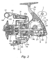
- a spinning reel in which an embodiment of the present invention is employed includes a handle assembly 1, a reel unit 2 for rotatably supporting the handle assembly 1, a rotor 3, and a spool 4.
- the rotor 3 is a unit for winding fishing line around the spool 4, and is rotatably supported at the front portion of the reel unit 2.
- the spool 4 serves to wind fishing line around the outer peripheral surface thereof, and is disposed on the front of the rotor 3 so as to be capable of moving back and forth.
- the handle assembly 1 is allowed to be mounted to either the right side ( FIGS. 1 and 2 ) or the left side ( FIGS. 3 and 4 ) of the reel unit 2, and a bolt member 19 with a cap is mounted to the side of the reel unit 2 on which the handle assembly 1 is not being mounted (right side of the reel unit 2 in FIGS. 3 and 4 ).
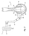
- the handle assembly 1 includes a handle shaft portion 7, a handle arm 8, a handle grip 9, and a tubular member 70.
- the handle shaft portion 7 is mounted to the inner peripheral portion of a master gear shaft 10 so as not to be allowed to rotate relative to the master gear shaft 10, and is disposed so that the tip end portion thereof protrudes outward in the axial direction compared to the tip end portion of the master gear 10.
- the handle arm 8 extends in the radial direction from the tip end portion of the handle shaft portion 7, and is mounted to the handle shaft portion 7 so as to be capable of pivoting with respect to the handle shaft portion 7.
- the handle grip 9 is mounted to the tip of the handle arm 8.
- the tubular member 70 is non-rotatably engaged with the tip end portion of the master gear shaft 10, and is non-rotatably engaged with the base end portion of the handle arm 8.
- the handle shaft portion 7 is formed to have a non-circular outer shape (e.g., rectangular), and is mounted to a through-hole 10a of the master gear shaft 10 so as not to be allowed to rotate but to be allowed to move in the axial direction.
- a female threaded portion 7a is formed in the inner peripheral side of the end portion (right end portion in FIG. 4 ) of the handle shaft portion 7, and a male threaded portion 19a of the bolt member 19 with a cap is screwed into the female threaded portion 7a of the handle shaft portion 7 that is mounted to the through-hole 10a. Accordingly, the handle shaft portion 7 is retained with respect to the master gear shaft 10.
- a handle arm 8 is fixed to a tip end portion 7b (left end portion in FIG. 4 ) of the handle shaft portion 7 by means of a bolt member 20.
- the handle arm 8 is a rod-shaped member made of a material such as, but not limited to, aluminum alloy and is formed to be bent to a certain degree toward the opposed side to the reel unit 2.
- An end of the handle arm 8 (lower end portion in FIG. 3 ) is coupled to the tip end portion (left end portion in FIG. 3 ) of the handle shaft portion 7 by means of the bolt member 20 so as to be allowed to pivot in directions toward and away from the reel unit 2.
- the handle grip 9 is rotatably mounted to the other end (upper end portion in FIG. 3 ) of the handle arm 8.
- the handle grip 9 includes a shaft portion 9b and a grip portion 9a.
- the shaft portion 9b is mounted to the handle arm 8 so as to be capable of rotating around an axis approximately parallel to the handle shaft portion 7.
- the grip portion 9a is fixed to the tip of the shaft portion 9b and is held by an angler.
- the grip portion 9a can be made of a synthetic resin, a cork, or the like.
- the shaft portion 9b can be made of metal or any combination thereof.
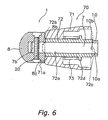
- the tubular member 70 includes a first tubular member 71, a second tubular member 72, and a biasing or urging member 73, preferably a spring member.
- the first tubular member 71 has a tubular shape and is provided separately from the handle shaft portion 7.
- the second tubular member 72 is mounted to the inner peripheral side of the first tubular member 71.
- the second tubular member 72 is also non-rotatably engaged with the tip end portion of the master gear shaft 10 and the base end portion of the handle arm 8.
- the spring member 73 is disposed between the first tubular member 71 and the second tubular member 72, and urges the first tubular member 71 toward the handle arm 8.
- the first tubular member 71 is mounted to the outer peripheral portion of the second tubular member 72 so as to cover the entire second tubular member 72.
- the first tubular member 71 is a tubular-shaped member wherein the diameter thereof gradually decreases to a certain extent toward the handle arm 8.
- the tip end portion (left end portion in FIG. 5 ) of the first tubular member 71 includes a contact portion 71a that is allowed to make contact with a contact portion 8a of the base end portion of the handle arm 8.
- the contact portion 71a of the first tubular member 71 is press against the contact portion 8a of the base end portion of the handle arm 8. Accordingly, the handle arm 8 is non-pivotably fixed to the reel unit 2.
- a non-circular portion 72a of the inner peripheral portion of the second tubular member 72 is mounted to the handle shaft portion 7 so as not to be allowed to rotate relative to the handle shaft 7 but to be allowed to move in the axial direction.
- the first tubular member 71 is mounted to the outer peripheral portion of the second tubular member 72 so as to be urged toward the handle arm 8 (leftward in FIG. 5 ) by means of the compressed spring member 73.
- the second tubular member 72 includes an engaging portion 72b, a second engaged portion 72c, and an annular abutment 72d.
- the engaging portion 72b for example, is composed of two protrusions that protrude from the tip end portion (left side in FIG.
- the second engaged portion 72c is composed of four recesses that are formed in the rear end (right side in FIG. 5 ) of the second tubular member 72 and are formed to be dented toward the handle arm 8.
- the abutment 72d is formed to protrude from the outer peripheral portion of the second tubular member 72 and function as a portion making contact with the rear end (right side in FIG. 5 ) of the spring member 73.
- the contact portion 8a of the handle arm 8 includes a first engaged portion 8b in the form of two recesses. The engaging portion 72b is allowed to engage with the first engaged portion 8b.
- the engaging portion 72b When the engaging portion 72b is engaged with the first engaged portion 8b, the handle arm 8 and the second tubular member 72 are prevented from rotating relatively to each other.
- the second engaged portion 72c is allowed to engage with an engaging portion 10b that includes four protrusions that protrude from the tip end portion of the master gear shaft 10 toward the handle arm 8.
- the engaging portion 10b When the engaging portion 10b is engaged with the second engaged portion 72c, the second tubular member 72 and the master gear shaft 10 are prevented from rotating relative to each other.
- the engaging portion 72b has a tapered portion that extends toward the handle arm 8.
- the engaging portion 72b is reliably allowed to engage with the first engaged portion 8b by moving the taper portion of the engaging portion 72b in the axial direction. Accordingly, it is possible to prevent wobbling from being generated when the engaging portion 72b is engaged with the engaged portion 8b.
- the reel unit 2 includes a reel body 2a in which an opening is formed, a lid member 2b that is detachably/reattachably mounted to the reel body 2a so as to cover the opening, a rod attachment leg 2c that extends obliquely upward and frontward from the lid member 2b, and a cover member 2d that is mounted to the reel body 2a and lid member 2b so as to cover the area raging from the rear portion to the lower portion of the reel body 2a and lid member 2b.
- the reel body 2a has a space in the interior thereof.
- a rotor driving mechanism 5 for rotating the rotor 3 in conjunction with the rotation of the handle assembly 1 and an oscillating mechanism 6 for winding fishing line by moving the spool 4 back and forth are provided in the space.
- the rotor driving mechanism 5 includes a master gear 11 that rotates with the master gear shaft 10 to which the handle shaft portion 7 of the handle assembly 1 is non-rotatably mounted, and a pinion gear 12 that meshes with the master gear 11.
- the master gear shaft 10 is a tubular member that is integrally formed with the master gear 11, and includes the through-hole 10a on the inner peripheral portion thereof, which has a non-circular shape such as rectangular or the like.
- the master gear shaft 10 is rotatably supported in the reel unit 2 by bearings 16 and 17 that are mounted to the inner peripheral portions of bosses 2e and 2f protruding toward the sides of the reel unit 2.
- the master gear 11 is a face gear that meshes with the pinion gear 12.
- the pinion gear 12 is formed in a tubular shape and penetrates the center portion of the rotor 3. Also, a front portion 12a of the pinion gear 12 is fixed to the rotor 3 by a nut 13. In addition, the intermediate portion and the rear end portion of the pinion gear 12 are rotatably supported in the reel unit 2 through bearings 14a and 14b, respectively.
- the oscillating mechanism 6 is a mechanism for moving the spool 4 back and forth together with a drag mechanism 60 by moving a spool shaft 15 back and forth, which penetrates the center portion of the spool 4 and is coupled to the drag mechanism 60.
- the oscillating mechanism 6 includes a worm shaft 21 that is disposed below and parallel to the spool shaft 15, a slider 22 that moves along the warm shaft 21 in a front-to-rear direction, and an intermediate gear 23 that is fixed to the tip of the worm shaft 21.
- the slider 22 is non-rotatably fixed to the rear end of the spool shaft 15.
- the intermediate gear 23 meshes with the pinion gear 12 through a reduction gear (not illustrated in the figures).
- the reciprocating speed of the oscillation mechanism 6 is slowed down by the reduction gear, and accordingly it is possible to densely wind the fishing line onto the spool 4.
- the rotor 3 includes a cylindrical portion 30, a first rotor arm 31 and a second rotor arm 32 that are arranged to be opposed to each other on the sides of the cylindrical portion 30.
- the cylindrical portion 30, the first rotor arm 31, and the second rotor arm 32 are integrally formed.
- a front wall 33 is formed in the front part of the cylindrical portion 30, and a boss 33a is formed in the center portion of the front wall 33.
- a through-hole is formed in the center portion of the boss 33a.
- the front portion 12a of the pinion gear 12 and the spool shaft 15 penetrate the through-hole.
- the nut 13 is disposed at the front of the front wall 33, and the front portion 12a of the pinion gear 12 is fixed to the rotor 3 by the nut 13.
- the first rotor arm 31 curves convexly outward and extends forward from the cylindrical portion 30.
- a first bail support member 40 is pivotably mounted to the outer peripheral side of the tip of the first rotor arm 31.
- a line roller 41 for guiding the fishing line onto the spool 4 is mounted to the tip of the first bail support member 40.
- the second rotor arm 32 curves convexly outward and extends forward from the cylindrical portion 30.
- a second bail support member 42 is pivotably mounted to the outer peripheral side of the tip of the second rotor arm 32.
- a bail member 43 having a curved U-shape is made of wire and fixed between the line roller 41 and the second bail support member 42.
- the first bail support member 40, the second bail support member 42, the line roller 41, and the bail member 43 make up a bail arm 44.
- the bail arm 44 is allowed to swing between a line-guiding posture as illustrated in FIG.2 and a line-releasing posture that flips from the line-guiding posture.
- An anti-reverse rotation mechanism 50 for preventing/allowing reverse rotation of the rotor 3 is disposed in the interior of the cylindrical portion 30 of the rotor 3.
- the anti-reverse rotation mechanism 50 includes a roller-type one-way clutch 51 with a freely rotating inner ring, and a switching mechanism 52 that switches the one-way clutch 51 between an operating state (i.e., reverse rotation is prohibited) and a non-operating state (i.e., reverse rotation is allowed).
- the spool 4 is disposed between the first rotor arm 31 and the second rotor arm 32 of the rotor 3, and is mounted to the tip of the spool shaft 15 through the drag mechanism 60.
- the second tubular member 72 and the master gear shaft 10 are prevented from relatively rotating with each other by engaging the engaging portion 10b of the master gear shaft 10 with the second engaged portion 72c of the second tubular member 72 forming a part of the tubular member 70, and the handle arm 8 and the second tubular member 72 are prevented from relatively rotating with each other by engaging the engaging portion 72b of the second tubular member 72 forming a part of the tubular member 70 with the first engaged member 8b of the handle arm 8.
- a handle assembly including a first and a second tubular member is exemplified, but the present invention is not limited thereto, and may include only one tubular member, preferably one connected directly to the master gear shaft. In this embodiment, there would be no need for the abutment 72d or the biasing or urging member 73.
- a spinning reel including a front drag mechanism is exemplified, but the present invention is not limited thereto, and may be applied to a spinning reel including both a front drag mechanism and a lever drag mechanism.
- the foregoing description of the embodiment according to the present invention is provided for illustration only, and not for the purpose of limiting the invention as defined by the appended claims and their equivalents. Thus, the scope of the invention is not limited to the disclosed embodiment.
Landscapes
- Life Sciences & Earth Sciences (AREA)
- Environmental Sciences (AREA)
- Animal Husbandry (AREA)
- Biodiversity & Conservation Biology (AREA)
Claims (8)
- Griffanordnung (1) für eine Spinnrolle, konfiguriert um integral drehbar zu sein mit einer Hauptgetriebewelle, wobei die Hauptgetriebewelle (10) drehbar an einer Rolleneinheit (2) der Spinnrolle montiert ist, wobei die Griffanordnung umfasst:einen Griffarm (8) mit einem Basisendabschnitt, konfiguriert um integral drehbar zu sein mit der Hauptgetriebewelle;einen Griff-Wellen-Abschnitt (7) eingegriffen und integral drehbar mit der Hauptgetriebewelle (10) und dem Griffarm;ein rohrförmiges Element (70),dadurch gekennzeichnet, dass das rohrförmige Element konfiguriert ist um nicht drehbar eingegriffen zu sein mit der Hauptgetriebewelle (10) und dem Griffarm (8).
- Griffanordnung nach Anspruch 1, bei welchem des rohrförmige Element (70) ein erstes rohrförmiges Element (71) und ein zweites rohrförmiges Elemente (72) enthält, wobei das erste rohrförmige Element montiert ist an einen äußeren peripheren Abschnitt des zweiten rohrförmigen Elementes.
- Griffanordnung nach Anspruch 2, bei welchem das rohrförmige Element (72) ein erstes Ende mit einem Eingriffsabschnitt (72b) aufweist, mit zumindest einem sich verjüngenden Vorsprung, sich erstreckend von dem ersten Ende hin zu dem Griffarm (8).
- Griffanordnung nach Anspruch 2 oder 3, bei welchem das zweite rohrförmige Element (72) ein zweites Ende mit einem eingegriffenen Abschnitt (72c) aufweist, mit zumindest einer Aussparung darin, sich erstreckend von dem zweiten Ende hin zu dem Griffarm (8).
- Griffanordnung nach einem der Ansprüche 2 bis 4, bei welchem das erste rohrförmige Element einen Innenkontaktfläche enthält.
- Griffanordnung nach einem der Ansprüche 2 bis 5, bei welchem das zweite rohrförmige Element (72) einen Anschlag (72d) enthält, vorspringend von dem äußeren peripheren Abschnitt.
- Griffanordnung nach den Ansprüchen 5 und 6, ferner umfassend, ein Beaufschlagungselement (73),
wobei das Beaufschlagungselement angeordnet ist zwischen der inneren Kontaktfläche und dem Anschlag, zum Beaufschlagen des ersten rohrförmigen Elementes hin zum Griffarm. - Spinnrolle, umfassend:eine Rolleneinheit (2),einen Rotor (3), drehbar gestützt an der Rolleneinheit;eine Spule (4), angeordnet an dem Rotor;eine Hauptgetriebewelle (10), drehbar montiert an der Rolleneinheit; undeine Griffanordnung (1), wie definiert in einem der Ansprüche 1 bis 7.
Applications Claiming Priority (1)
| Application Number | Priority Date | Filing Date | Title |
|---|---|---|---|
| JP2007032492A JP5236883B2 (ja) | 2007-02-13 | 2007-02-13 | スピニングリールのハンドル組立体 |
Publications (2)
| Publication Number | Publication Date |
|---|---|
| EP1958504A1 EP1958504A1 (de) | 2008-08-20 |
| EP1958504B1 true EP1958504B1 (de) | 2010-06-16 |
Family
ID=39531410
Family Applications (1)
| Application Number | Title | Priority Date | Filing Date |
|---|---|---|---|
| EP08002563A Active EP1958504B1 (de) | 2007-02-13 | 2008-02-12 | Angelrollengriffanordnung |
Country Status (10)
| Country | Link |
|---|---|
| US (1) | US7815138B2 (de) |
| EP (1) | EP1958504B1 (de) |
| JP (1) | JP5236883B2 (de) |
| KR (1) | KR101396775B1 (de) |
| CN (1) | CN101243784B (de) |
| AT (1) | ATE471075T1 (de) |
| DE (1) | DE602008001514D1 (de) |
| MY (1) | MY143446A (de) |
| SG (1) | SG145639A1 (de) |
| TW (1) | TWI423763B (de) |
Families Citing this family (12)
| Publication number | Priority date | Publication date | Assignee | Title |
|---|---|---|---|---|
| JP5205120B2 (ja) * | 2008-04-28 | 2013-06-05 | 株式会社シマノ | 釣り用リールのハンドル把手 |
| JP5185177B2 (ja) * | 2009-03-30 | 2013-04-17 | 株式会社シマノ | スピニングリールのハンドル取付構造 |
| JP5495669B2 (ja) * | 2009-08-20 | 2014-05-21 | 株式会社シマノ | スピニングリールのハンドル組立体 |
| JP2011193855A (ja) * | 2010-03-24 | 2011-10-06 | Shimano Components Malaysia Sdn Bhd | マスターギア組立体 |
| JP5937892B2 (ja) * | 2012-05-29 | 2016-06-22 | グローブライド株式会社 | 魚釣用スピニングリール |
| KR102005125B1 (ko) | 2012-05-29 | 2019-07-29 | 글로브라이드 가부시키가이샤 | 낚시용 스피닝 릴 |
| JP6027805B2 (ja) * | 2012-07-24 | 2016-11-16 | 株式会社シマノ | スピニングリールのハンドル組立体 |
| JP6132543B2 (ja) * | 2012-12-20 | 2017-05-24 | 株式会社シマノ | スピニングリール |
| JP5995321B2 (ja) * | 2013-02-28 | 2016-09-21 | グローブライド株式会社 | 魚釣用スピニングリール |
| JP6389370B2 (ja) * | 2014-03-28 | 2018-09-12 | グローブライド株式会社 | 魚釣用スピニングリール |
| JP6505405B2 (ja) * | 2014-09-26 | 2019-04-24 | シマノコンポネンツ マレーシア エスディーエヌ.ビーエッチディー. | ハンドル組立体 |
| JP7112306B2 (ja) * | 2018-10-05 | 2022-08-03 | 株式会社シマノ | 魚釣用リール |
Family Cites Families (24)
| Publication number | Priority date | Publication date | Assignee | Title |
|---|---|---|---|---|
| JPS5255888U (de) * | 1975-10-21 | 1977-04-22 | ||
| JPS613323Y2 (de) | 1980-09-22 | 1986-02-01 | ||
| JPS5977364U (ja) * | 1982-11-11 | 1984-05-25 | 株式会社シマノ | 釣用リ−ル |
| JPS613323U (ja) | 1984-06-13 | 1986-01-10 | 株式会社日立ホームテック | 調理家具組込形電子レンジ |
| US5244166A (en) * | 1989-11-20 | 1993-09-14 | Shimano, Inc. | Handle fixing structure for spinning reel |
| JPH08856Y2 (ja) * | 1989-11-20 | 1996-01-17 | 島野工業株式会社 | 魚釣り用スピニングリールのハンドル固定構造 |
| JPH03114957U (de) * | 1990-03-12 | 1991-11-27 | ||
| JP2522557Y2 (ja) | 1990-07-04 | 1997-01-16 | 株式会社シマノ | リール用ハンドル軸支持部のシール構造 |
| JPH0529380U (ja) * | 1991-02-28 | 1993-04-20 | リヨービ株式会社 | 魚釣用リールのハンドル |
| DE69407696T2 (de) * | 1993-09-08 | 1998-04-16 | Daiwa Seiko Inc | Kurbelmontage-Anordnung in Angelhaspeln |
| JP3839972B2 (ja) * | 1998-09-17 | 2006-11-01 | 株式会社シマノ | スピニングリールの防水構造 |
| JP2000157118A (ja) * | 1998-11-26 | 2000-06-13 | Ryobi Ltd | 魚釣り用リールのハンドル機構 |
| JP2003079287A (ja) * | 2001-09-12 | 2003-03-18 | Shimano Inc | スピニングリールのハンドル取付構造 |
| JP2003284464A (ja) * | 2002-03-28 | 2003-10-07 | Shimano Inc | 釣り用リールのハンドル取付構造 |
| JP4045167B2 (ja) * | 2002-05-01 | 2008-02-13 | 株式会社シマノ | スピニングリールのハンドル組立体 |
| US6626385B1 (en) * | 2002-08-01 | 2003-09-30 | Daiwa Seiko, Inc. | Spinning reel for fishing |
| CN2603960Y (zh) * | 2002-12-23 | 2004-02-18 | 鸿富锦精密工业(深圳)有限公司 | 计算机面板枢轴结构 |
| JP4015957B2 (ja) * | 2003-01-20 | 2007-11-28 | 株式会社シマノ | スピニングリールのハンドル組立体 |
| JP3908673B2 (ja) * | 2003-01-31 | 2007-04-25 | ダイワ精工株式会社 | 魚釣用リ−ルのハンドル |
| JP2004236571A (ja) * | 2003-02-05 | 2004-08-26 | Shimano Inc | 釣り用リールのハンドル取付構造 |
| SG121940A1 (en) * | 2004-10-06 | 2006-05-26 | Shimano Kk | Handle knob and handle assembly for a fishing reel |
| JP2006217848A (ja) * | 2005-02-09 | 2006-08-24 | Shimano Inc | スピニングリールのハンドル組立体 |
| US7178752B1 (en) * | 2005-08-01 | 2007-02-20 | Okuma Fishing Tackle Co., Ltd. | Crank handle for spinning reel |
| JP4794355B2 (ja) * | 2006-05-30 | 2011-10-19 | グローブライド株式会社 | 魚釣用リールのハンドル取り付け構造 |
-
2007
- 2007-02-13 JP JP2007032492A patent/JP5236883B2/ja active Active
-
2008
- 2008-01-29 TW TW097103334A patent/TWI423763B/zh active
- 2008-01-31 KR KR1020080010009A patent/KR101396775B1/ko active IP Right Grant
- 2008-02-04 US US12/025,557 patent/US7815138B2/en not_active Expired - Fee Related
- 2008-02-11 MY MYPI20080239A patent/MY143446A/en unknown
- 2008-02-12 SG SG200801162-9A patent/SG145639A1/en unknown
- 2008-02-12 DE DE602008001514T patent/DE602008001514D1/de active Active
- 2008-02-12 EP EP08002563A patent/EP1958504B1/de active Active
- 2008-02-12 AT AT08002563T patent/ATE471075T1/de not_active IP Right Cessation
- 2008-02-13 CN CN2008100082152A patent/CN101243784B/zh active Active
Also Published As
| Publication number | Publication date |
|---|---|
| US7815138B2 (en) | 2010-10-19 |
| US20080191079A1 (en) | 2008-08-14 |
| TWI423763B (zh) | 2014-01-21 |
| EP1958504A1 (de) | 2008-08-20 |
| CN101243784A (zh) | 2008-08-20 |
| MY143446A (en) | 2011-05-13 |
| JP2008193949A (ja) | 2008-08-28 |
| KR101396775B1 (ko) | 2014-05-19 |
| DE602008001514D1 (de) | 2010-07-29 |
| KR20080075776A (ko) | 2008-08-19 |
| SG145639A1 (en) | 2008-09-29 |
| TW200913879A (en) | 2009-04-01 |
| CN101243784B (zh) | 2011-10-12 |
| JP5236883B2 (ja) | 2013-07-17 |
| ATE471075T1 (de) | 2010-07-15 |
Similar Documents
| Publication | Publication Date | Title |
|---|---|---|
| EP1958504B1 (de) | Angelrollengriffanordnung | |
| JP4804279B2 (ja) | スピニングリール | |
| US7802744B2 (en) | Spinning reel | |
| EP2002715A1 (de) | Spule für eine Angelrolle | |
| US7628348B2 (en) | Reel unit of spinning reel | |
| EP2248418B1 (de) | Rotor für eine Angelrolle | |
| US7070137B2 (en) | Handle assembly for a spinning reel | |
| US6978957B2 (en) | Spool support structure for a spinning reel | |
| US6929204B2 (en) | Method of manufacturing a spinning reel rotor | |
| US7007880B2 (en) | Fishing line guide mechanism for spinning reel | |
| JP2006238746A (ja) | 釣り用リールのハンドル把手 | |
| KR20040019947A (ko) | 스피닝 릴의 낚싯줄 안내 기구 | |
| EP1415534A1 (de) | Rotor für Angelwinde | |
| EP1425965A1 (de) | Spulenträgerstruktur für Angelwinde | |
| EP2036431A1 (de) | Angelrolle | |
| EP3180977B1 (de) | Angelrollenrotor und angelrolle | |
| JPH11169036A (ja) | 釣り用リール | |
| JP2004081154A5 (de) | ||
| JP2002000138A (ja) | スピニングリールのベール反転装置 | |
| JP2004313078A (ja) | スピニングリールのベール反転装置 | |
| JP2003174838A (ja) | スピニングリールのスプール | |
| JP2011092046A (ja) | スピニングリールの釣り糸案内機構 |
Legal Events
| Date | Code | Title | Description |
|---|---|---|---|
| PUAI | Public reference made under article 153(3) epc to a published international application that has entered the european phase |
Free format text: ORIGINAL CODE: 0009012 |
|
| AK | Designated contracting states |
Kind code of ref document: A1 Designated state(s): AT BE BG CH CY CZ DE DK EE ES FI FR GB GR HR HU IE IS IT LI LT LU LV MC MT NL NO PL PT RO SE SI SK TR |
|
| AX | Request for extension of the european patent |
Extension state: AL BA MK RS |
|
| 17P | Request for examination filed |
Effective date: 20081215 |
|
| AKX | Designation fees paid |
Designated state(s): AT BE BG CH CY CZ DE DK EE ES FI FR GB GR HR HU IE IS IT LI LT LU LV MC MT NL NO PL PT RO SE SI SK TR |
|
| GRAP | Despatch of communication of intention to grant a patent |
Free format text: ORIGINAL CODE: EPIDOSNIGR1 |
|
| GRAS | Grant fee paid |
Free format text: ORIGINAL CODE: EPIDOSNIGR3 |
|
| GRAA | (expected) grant |
Free format text: ORIGINAL CODE: 0009210 |
|
| AK | Designated contracting states |
Kind code of ref document: B1 Designated state(s): AT BE BG CH CY CZ DE DK EE ES FI FR GB GR HR HU IE IS IT LI LT LU LV MC MT NL NO PL PT RO SE SI SK TR |
|
| REG | Reference to a national code |
Ref country code: CH Ref legal event code: EP |
|
| REG | Reference to a national code |
Ref country code: IE Ref legal event code: FG4D |
|
| REF | Corresponds to: |
Ref document number: 602008001514 Country of ref document: DE Date of ref document: 20100729 Kind code of ref document: P |
|
| REG | Reference to a national code |
Ref country code: NL Ref legal event code: VDEP Effective date: 20100616 |
|
| PG25 | Lapsed in a contracting state [announced via postgrant information from national office to epo] |
Ref country code: LT Free format text: LAPSE BECAUSE OF FAILURE TO SUBMIT A TRANSLATION OF THE DESCRIPTION OR TO PAY THE FEE WITHIN THE PRESCRIBED TIME-LIMIT Effective date: 20100616 Ref country code: SE Free format text: LAPSE BECAUSE OF FAILURE TO SUBMIT A TRANSLATION OF THE DESCRIPTION OR TO PAY THE FEE WITHIN THE PRESCRIBED TIME-LIMIT Effective date: 20100616 Ref country code: NO Free format text: LAPSE BECAUSE OF FAILURE TO SUBMIT A TRANSLATION OF THE DESCRIPTION OR TO PAY THE FEE WITHIN THE PRESCRIBED TIME-LIMIT Effective date: 20100916 |
|
| LTIE | Lt: invalidation of european patent or patent extension |
Effective date: 20100616 |
|
| PG25 | Lapsed in a contracting state [announced via postgrant information from national office to epo] |
Ref country code: SI Free format text: LAPSE BECAUSE OF FAILURE TO SUBMIT A TRANSLATION OF THE DESCRIPTION OR TO PAY THE FEE WITHIN THE PRESCRIBED TIME-LIMIT Effective date: 20100616 Ref country code: LV Free format text: LAPSE BECAUSE OF FAILURE TO SUBMIT A TRANSLATION OF THE DESCRIPTION OR TO PAY THE FEE WITHIN THE PRESCRIBED TIME-LIMIT Effective date: 20100616 Ref country code: HR Free format text: LAPSE BECAUSE OF FAILURE TO SUBMIT A TRANSLATION OF THE DESCRIPTION OR TO PAY THE FEE WITHIN THE PRESCRIBED TIME-LIMIT Effective date: 20100616 Ref country code: FI Free format text: LAPSE BECAUSE OF FAILURE TO SUBMIT A TRANSLATION OF THE DESCRIPTION OR TO PAY THE FEE WITHIN THE PRESCRIBED TIME-LIMIT Effective date: 20100616 Ref country code: AT Free format text: LAPSE BECAUSE OF FAILURE TO SUBMIT A TRANSLATION OF THE DESCRIPTION OR TO PAY THE FEE WITHIN THE PRESCRIBED TIME-LIMIT Effective date: 20100616 |
|
| PG25 | Lapsed in a contracting state [announced via postgrant information from national office to epo] |
Ref country code: CY Free format text: LAPSE BECAUSE OF FAILURE TO SUBMIT A TRANSLATION OF THE DESCRIPTION OR TO PAY THE FEE WITHIN THE PRESCRIBED TIME-LIMIT Effective date: 20100616 Ref country code: PL Free format text: LAPSE BECAUSE OF FAILURE TO SUBMIT A TRANSLATION OF THE DESCRIPTION OR TO PAY THE FEE WITHIN THE PRESCRIBED TIME-LIMIT Effective date: 20100616 |
|
| PG25 | Lapsed in a contracting state [announced via postgrant information from national office to epo] |
Ref country code: EE Free format text: LAPSE BECAUSE OF FAILURE TO SUBMIT A TRANSLATION OF THE DESCRIPTION OR TO PAY THE FEE WITHIN THE PRESCRIBED TIME-LIMIT Effective date: 20100616 Ref country code: NL Free format text: LAPSE BECAUSE OF FAILURE TO SUBMIT A TRANSLATION OF THE DESCRIPTION OR TO PAY THE FEE WITHIN THE PRESCRIBED TIME-LIMIT Effective date: 20100616 |
|
| PG25 | Lapsed in a contracting state [announced via postgrant information from national office to epo] |
Ref country code: SK Free format text: LAPSE BECAUSE OF FAILURE TO SUBMIT A TRANSLATION OF THE DESCRIPTION OR TO PAY THE FEE WITHIN THE PRESCRIBED TIME-LIMIT Effective date: 20100616 Ref country code: RO Free format text: LAPSE BECAUSE OF FAILURE TO SUBMIT A TRANSLATION OF THE DESCRIPTION OR TO PAY THE FEE WITHIN THE PRESCRIBED TIME-LIMIT Effective date: 20100616 Ref country code: IS Free format text: LAPSE BECAUSE OF FAILURE TO SUBMIT A TRANSLATION OF THE DESCRIPTION OR TO PAY THE FEE WITHIN THE PRESCRIBED TIME-LIMIT Effective date: 20101016 Ref country code: CZ Free format text: LAPSE BECAUSE OF FAILURE TO SUBMIT A TRANSLATION OF THE DESCRIPTION OR TO PAY THE FEE WITHIN THE PRESCRIBED TIME-LIMIT Effective date: 20100616 Ref country code: BE Free format text: LAPSE BECAUSE OF FAILURE TO SUBMIT A TRANSLATION OF THE DESCRIPTION OR TO PAY THE FEE WITHIN THE PRESCRIBED TIME-LIMIT Effective date: 20100616 |
|
| PG25 | Lapsed in a contracting state [announced via postgrant information from national office to epo] |
Ref country code: IT Free format text: LAPSE BECAUSE OF FAILURE TO SUBMIT A TRANSLATION OF THE DESCRIPTION OR TO PAY THE FEE WITHIN THE PRESCRIBED TIME-LIMIT Effective date: 20100616 |
|
| PLBE | No opposition filed within time limit |
Free format text: ORIGINAL CODE: 0009261 |
|
| STAA | Information on the status of an ep patent application or granted ep patent |
Free format text: STATUS: NO OPPOSITION FILED WITHIN TIME LIMIT |
|
| PG25 | Lapsed in a contracting state [announced via postgrant information from national office to epo] |
Ref country code: DK Free format text: LAPSE BECAUSE OF FAILURE TO SUBMIT A TRANSLATION OF THE DESCRIPTION OR TO PAY THE FEE WITHIN THE PRESCRIBED TIME-LIMIT Effective date: 20100616 |
|
| 26N | No opposition filed |
Effective date: 20110317 |
|
| PG25 | Lapsed in a contracting state [announced via postgrant information from national office to epo] |
Ref country code: GR Free format text: LAPSE BECAUSE OF FAILURE TO SUBMIT A TRANSLATION OF THE DESCRIPTION OR TO PAY THE FEE WITHIN THE PRESCRIBED TIME-LIMIT Effective date: 20100917 |
|
| REG | Reference to a national code |
Ref country code: DE Ref legal event code: R097 Ref document number: 602008001514 Country of ref document: DE Effective date: 20110316 |
|
| PG25 | Lapsed in a contracting state [announced via postgrant information from national office to epo] |
Ref country code: MC Free format text: LAPSE BECAUSE OF NON-PAYMENT OF DUE FEES Effective date: 20110228 |
|
| REG | Reference to a national code |
Ref country code: IE Ref legal event code: MM4A |
|
| PG25 | Lapsed in a contracting state [announced via postgrant information from national office to epo] |
Ref country code: MT Free format text: LAPSE BECAUSE OF FAILURE TO SUBMIT A TRANSLATION OF THE DESCRIPTION OR TO PAY THE FEE WITHIN THE PRESCRIBED TIME-LIMIT Effective date: 20100616 |
|
| PG25 | Lapsed in a contracting state [announced via postgrant information from national office to epo] |
Ref country code: IE Free format text: LAPSE BECAUSE OF NON-PAYMENT OF DUE FEES Effective date: 20110212 |
|
| REG | Reference to a national code |
Ref country code: CH Ref legal event code: PL |
|
| PG25 | Lapsed in a contracting state [announced via postgrant information from national office to epo] |
Ref country code: CH Free format text: LAPSE BECAUSE OF NON-PAYMENT OF DUE FEES Effective date: 20120229 Ref country code: LI Free format text: LAPSE BECAUSE OF NON-PAYMENT OF DUE FEES Effective date: 20120229 |
|
| PG25 | Lapsed in a contracting state [announced via postgrant information from national office to epo] |
Ref country code: PT Free format text: LAPSE BECAUSE OF NON-PAYMENT OF DUE FEES Effective date: 20100616 |
|
| PG25 | Lapsed in a contracting state [announced via postgrant information from national office to epo] |
Ref country code: BG Free format text: LAPSE BECAUSE OF FAILURE TO SUBMIT A TRANSLATION OF THE DESCRIPTION OR TO PAY THE FEE WITHIN THE PRESCRIBED TIME-LIMIT Effective date: 20100916 Ref country code: TR Free format text: LAPSE BECAUSE OF FAILURE TO SUBMIT A TRANSLATION OF THE DESCRIPTION OR TO PAY THE FEE WITHIN THE PRESCRIBED TIME-LIMIT Effective date: 20100616 |
|
| PG25 | Lapsed in a contracting state [announced via postgrant information from national office to epo] |
Ref country code: ES Free format text: LAPSE BECAUSE OF FAILURE TO SUBMIT A TRANSLATION OF THE DESCRIPTION OR TO PAY THE FEE WITHIN THE PRESCRIBED TIME-LIMIT Effective date: 20100927 Ref country code: HU Free format text: LAPSE BECAUSE OF FAILURE TO SUBMIT A TRANSLATION OF THE DESCRIPTION OR TO PAY THE FEE WITHIN THE PRESCRIBED TIME-LIMIT Effective date: 20100616 |
|
| REG | Reference to a national code |
Ref country code: FR Ref legal event code: PLFP Year of fee payment: 9 |
|
| REG | Reference to a national code |
Ref country code: FR Ref legal event code: PLFP Year of fee payment: 10 |
|
| PGFP | Annual fee paid to national office [announced via postgrant information from national office to epo] |
Ref country code: LU Payment date: 20170204 Year of fee payment: 10 |
|
| REG | Reference to a national code |
Ref country code: FR Ref legal event code: PLFP Year of fee payment: 11 |
|
| PG25 | Lapsed in a contracting state [announced via postgrant information from national office to epo] |
Ref country code: LU Free format text: LAPSE BECAUSE OF NON-PAYMENT OF DUE FEES Effective date: 20180212 |
|
| PGFP | Annual fee paid to national office [announced via postgrant information from national office to epo] |
Ref country code: GB Payment date: 20210203 Year of fee payment: 14 |
|
| GBPC | Gb: european patent ceased through non-payment of renewal fee |
Effective date: 20220212 |
|
| PG25 | Lapsed in a contracting state [announced via postgrant information from national office to epo] |
Ref country code: GB Free format text: LAPSE BECAUSE OF NON-PAYMENT OF DUE FEES Effective date: 20220212 |
|
| REG | Reference to a national code |
Ref country code: DE Ref legal event code: R081 Ref document number: 602008001514 Country of ref document: DE Owner name: SHIMANO INC., SAKAI-SHI, JP Free format text: FORMER OWNER: SHIMANO COMPONENTS (MALAYSIA) SDN BHD, PONTIAN, JOHOR, MY |
|
| PGFP | Annual fee paid to national office [announced via postgrant information from national office to epo] |
Ref country code: FR Payment date: 20230110 Year of fee payment: 16 |
|
| P01 | Opt-out of the competence of the unified patent court (upc) registered |
Effective date: 20230426 |
|
| PGFP | Annual fee paid to national office [announced via postgrant information from national office to epo] |
Ref country code: DE Payment date: 20231228 Year of fee payment: 17 |