EP2248418B1 - Rotor für eine Angelrolle - Google Patents
Rotor für eine Angelrolle Download PDFInfo
- Publication number
- EP2248418B1 EP2248418B1 EP10151208A EP10151208A EP2248418B1 EP 2248418 B1 EP2248418 B1 EP 2248418B1 EP 10151208 A EP10151208 A EP 10151208A EP 10151208 A EP10151208 A EP 10151208A EP 2248418 B1 EP2248418 B1 EP 2248418B1
- Authority
- EP
- European Patent Office
- Prior art keywords
- rotor
- cover member
- arm
- mounting bracket
- flange portion
- Prior art date
- Legal status (The legal status is an assumption and is not a legal conclusion. Google has not performed a legal analysis and makes no representation as to the accuracy of the status listed.)
- Active
Links
- 238000009987 spinning Methods 0.000 title claims description 19
- 230000007246 mechanism Effects 0.000 description 40
- 230000036544 posture Effects 0.000 description 12
- XLYOFNOQVPJJNP-UHFFFAOYSA-N water Substances O XLYOFNOQVPJJNP-UHFFFAOYSA-N 0.000 description 6
- 229910000838 Al alloy Inorganic materials 0.000 description 5
- 230000010355 oscillation Effects 0.000 description 5
- 230000002093 peripheral effect Effects 0.000 description 5
- 239000000126 substance Substances 0.000 description 4
- VYZAMTAEIAYCRO-UHFFFAOYSA-N Chromium Chemical compound [Cr] VYZAMTAEIAYCRO-UHFFFAOYSA-N 0.000 description 2
- PXHVJJICTQNCMI-UHFFFAOYSA-N Nickel Chemical compound [Ni] PXHVJJICTQNCMI-UHFFFAOYSA-N 0.000 description 2
- 229910045601 alloy Inorganic materials 0.000 description 2
- 239000000956 alloy Substances 0.000 description 2
- 230000005540 biological transmission Effects 0.000 description 2
- 230000006866 deterioration Effects 0.000 description 2
- 230000004048 modification Effects 0.000 description 2
- 238000012986 modification Methods 0.000 description 2
- 238000007747 plating Methods 0.000 description 2
- 230000001105 regulatory effect Effects 0.000 description 2
- 230000004044 response Effects 0.000 description 2
- 238000010079 rubber tapping Methods 0.000 description 2
- 150000003839 salts Chemical class 0.000 description 2
- 241000276420 Lophius piscatorius Species 0.000 description 1
- 230000009471 action Effects 0.000 description 1
- 230000000903 blocking effect Effects 0.000 description 1
- 238000005266 casting Methods 0.000 description 1
- 238000004512 die casting Methods 0.000 description 1
- 230000009977 dual effect Effects 0.000 description 1
- 238000005242 forging Methods 0.000 description 1
- 230000002452 interceptive effect Effects 0.000 description 1
- 229910052751 metal Inorganic materials 0.000 description 1
- 239000002184 metal Substances 0.000 description 1
- 229910052759 nickel Inorganic materials 0.000 description 1
- 239000013535 sea water Substances 0.000 description 1
- 238000004804 winding Methods 0.000 description 1
Images


Classifications
-
- A—HUMAN NECESSITIES
- A01—AGRICULTURE; FORESTRY; ANIMAL HUSBANDRY; HUNTING; TRAPPING; FISHING
- A01K—ANIMAL HUSBANDRY; AVICULTURE; APICULTURE; PISCICULTURE; FISHING; REARING OR BREEDING ANIMALS, NOT OTHERWISE PROVIDED FOR; NEW BREEDS OF ANIMALS
- A01K89/00—Reels
- A01K89/01—Reels with pick-up, i.e. with the guiding member rotating and the spool not rotating during normal retrieval of the line
- A01K89/0108—Pick-up details
- A01K89/01081—Guiding members on rotor axially rearward of spool
- A01K89/01082—Guiding members shiftable on rotor
- A01K89/01083—Guiding members shiftable on rotor to wind position by rotor drive
-
- A—HUMAN NECESSITIES
- A01—AGRICULTURE; FORESTRY; ANIMAL HUSBANDRY; HUNTING; TRAPPING; FISHING
- A01K—ANIMAL HUSBANDRY; AVICULTURE; APICULTURE; PISCICULTURE; FISHING; REARING OR BREEDING ANIMALS, NOT OTHERWISE PROVIDED FOR; NEW BREEDS OF ANIMALS
- A01K89/00—Reels
- A01K89/01—Reels with pick-up, i.e. with the guiding member rotating and the spool not rotating during normal retrieval of the line
- A01K89/0114—Reciprocating mechanisms
-
- A—HUMAN NECESSITIES
- A01—AGRICULTURE; FORESTRY; ANIMAL HUSBANDRY; HUNTING; TRAPPING; FISHING
- A01K—ANIMAL HUSBANDRY; AVICULTURE; APICULTURE; PISCICULTURE; FISHING; REARING OR BREEDING ANIMALS, NOT OTHERWISE PROVIDED FOR; NEW BREEDS OF ANIMALS
- A01K89/00—Reels
- A01K89/01—Reels with pick-up, i.e. with the guiding member rotating and the spool not rotating during normal retrieval of the line
- A01K89/0117—Anti-reverse mechanisms
Definitions
- the present invention relates to a rotor, and in particular, to a rotor coupled to a pinion gear of a spinning reel so as to rotate integrally with the pinion gear and configured to reel out a fishing line forward.
- a spinning reel is provided with a rotor for winding a fishing line onto a spool.
- the rotor is integrally-rotatably coupled to a part of a reel body in front of a pinion gear rotatably supported by the reel body.
- the rotor includes a rotor body composed of a coupler, a first rotor arm and a second rotor arm.
- the coupler integrally-rotatably coupled to the pinion gear.
- the first rotor arm forwardly extends from a first side of the rear end of the coupler while being spaced apart from the outer periphery of the coupler.
- the second rotor arm forwardly extends from a second side of the rear end of the coupler while being spaced apart from the outer periphery of the coupler.
- the conventional rotor of this type has been known to further include an outer cover member and a rear cover member.
- the outer cover member is composed of first and second cover members for covering outside of the first and second rotor arms of the rotor body, respectively.
- the rear cover member covers the rear end of the coupler.
- Laid-Open Japan Patent Publication No. JP-A-2003-125678 discloses a rotor of this type.
- the outer cover member has a externally-bulging curved face. Opposed sides of the rear cover member are joined to the rear end of the outer cover member. Therefore, the joining parts between the outer cover member and the rear cover member are formed in a three-dimensional curved shape.
- the outer cover member is fixed to the outer faces of the first and second rotor arms by way of screw members (e.g., tapping screws and round-head screws).
- the screw members are inserted into the outer cover member in an inwardly radial direction and screwed into the first and second rotor arms.
- the rear cover member is fixed to the rear face of the rotor body with screw members (e.g., tapping screws and round-head screws).
- the screw members are inserted into the rear cover member from behind and screwed into the rotor body.
- a circular opening is formed in the rear cover member for allowing a flange of the reel body to be disposed.
- screw members are used for fixation of the outer cover member and the rear cover member. Screw member are inserted into the outer cover member from its outside, whereas screw members are inserted into the rear cover member from its behind.
- through-holes are formed in the outer faces of the outer cover member and the rear face of the rear cover member for allowing the screw members to penetrate. Accordingly, the head portions of the screw members are exposed to the outside.
- foreign substance e.g., bait
- the outer cover member is attached to the first and second rotor arms without any clearance. Therefore, even if the outer cover member is washed from its outside with shower, there are less chances that water enters the interior of the rotor. Additionally, even if water attaches to the head portions of the screw members, the attached water will be scattered by centrifugal force to be generated in rotation of the rotor.
- the opening is formed in the rear cover member for disposing the flange therein. Therefore, when the head portions of the screw members are washed with shower in order to remove the foreign substance or slat attached thereto, there are chances that water enters mechanisms in the interior of the reel body (e.g., an anti-reverse mechanism and a rotor driving mechanism) through a clearance between the opening and the flange. When water enters the interior of the rotor body, water attaches to the mechanisms disposed therein. This may cause malfunctioning of the mechanisms.
- Document EP1260138 discloses a rotor for a spinning reel according to the preamble of claim 1.
- aspects of the present invention have been created to solve the above-mentioned problems occurring in the conventional practice, and to prevent a head portion of a screw member from being exposed to the outside in a structure for fixing a rear cover member to a rotor body.
- a rotor for a spinning reel is configured to reel out a fishing line forward.
- the rotor is connected to a pinion gear of the spinning reel in order to rotate integrally with the pinion gear.
- the rotor comprises a rotor body including a tubular member, a first rotor arm, and a second rotor arm.
- the tubular member is coupled to the pinion gear to rotate integrally with the pinion gear.
- the first rotor arm is arranged to extend forward from a first side of a rear end of the tubular member.
- the second rotor arm is arranged to extend forward from a second side of the rear end of the tubular member.
- the first and second rotor arms are spaced apart from an outer periphery of the tubular member.
- the rotor further comprises an outer cover member that covers the outside of at least either of the first and second rotor arms, and a rear cover member that covers a rear end of the tubular member.
- the rear cover member is coupled to a rear end of the outer cover member.
- the rotor also comprises at least one mounting bracket configured to attach the rear cover member to the rotor body by way of a screw member.
- the mounting bracket is disposed forward of the rear cover member along the axial direction of the rotor body so that the mounting bracket is covered by the outer cover member.
- the at least one mounting bracket includes an axial flange portion and a radial flange portion having a through-hole for receiving the screw member.
- the axial flange portion extends forward along the axial direction from a rim of the rear cover member.
- the radial flange portion extends from an end of the axial flange portion in a radially outward direction.
- the outer cover member includes a first cover member to cover the outside of the first rotor arm, and a second cover member to cover the outside of the second rotor arm.
- the at least one mounting bracket further includes a first mounting bracket and a second mounting bracket.
- the radial flange portion for the first and second mounting brackets are disposed forward along the axial direction of where the first and second cover members are coupled to the rear cover member.
- the first and second mounting brackets are disposed on the opposite sides of the rear cover member through a center line substantially perpendicular to and passing through an axis of rotation of the rotor.
- FIG. 1 is a side view of a spinning reel that an embodiment of the present invention is adopted
- FIG. 2 is a cross-sectional side view of the spinning reel
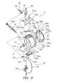
- FIG. 3 is an exploded oblique view of a rotor of the spinning reel
- FIG. 4 is an exploded cross-sectional side view of the rotor body and first to third cover members
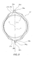
- FIG. 5 is a front view of the third cover member
- FIG. 6 is an exploded cross-sectional side view of the rotor body and first to third cover members coupled together.
- a spinning reel is illustrated in accordance with an embodiment of the present invention and includes a reel body 2, a rotor 3 and a spool 4.
- the reel body 2 rotatably supports a handle 1.
- the rotor 3 winds a fishing line onto the spool 4.
- the rotor 3 is rotatably supported at the front part of the reel body 2.
- the spool 4 winds the fishing line onto the outer periphery thereof.
- the spool 4, movably back and forth, is disposed at the front part of the rotor 3.
- the handle 1 can be attached to either the left side (see FIG. 1 ) or the right side of the reel body 2. As illustrated in FIGS.
- the handle 1 includes a handle arm 8, a knob shaft (not illustrated in the figure) and a handle knob 9.
- the handle arm 8 is attached to the tip of a handle shaft 8a (see FIG. 2 ).
- the handle arm 8 extends perpendicular to the handle shaft 8a.
- the knob shaft is fixed to the tip of the handle arm 8.
- the handle knob 9 is rotatably attached to the knob shaft.
- the reel body 2 includes a reel body 2a, a lid member 2b and a rod attachment leg 2c.
- the reel body 2a includes an opening.
- the reel body 2a is made of, e.g., aluminum alloy.
- the lid member 2b is detachably attached to the reel body 2a for covering the opening.
- the lid member 2b is made of e.g., aluminum alloy.
- the rod attachment leg 2c forwardly extends from the reel body 2a in an obliquely upward direction.
- the reel body 2a includes an inner space.
- the inner space communicates with the opening.
- the reel body 2a accommodates a rotor driving mechanism 5 and an oscillation mechanism 6 in the inner space.
- the rotor driving mechanism 5 rotates the rotor 3 in conjunction with rotation of the handle 1.
- the oscillation mechanism 6 moves the spool 4 back and forth for uniformly rewinding the fishing line.
- a flange 2e is formed in the reel body 2a and the lid member 2b.
- a cylindrical portion 2f is further formed in the reel body 2a. The cylindrical portion 2f forwardly protrudes from the flange 2e.
- a guard member 17 covers back of the reel body 2.
- the rotor driving mechanism 5 includes a main gear shaft 10, a main gear 11 and a pinion gear 12.
- the handle shaft 8a of the handle 1 is fixed to the main gear shaft 10.
- the main gear 11 is configured to rotate with the main gear shaft 10.
- the pinion gear 12 meshes with the main gear 11.
- the main gear shaft 10 is a hollow shaft made of stainless alloy. Both ends of the main gear shaft 10 are supported by bearings (not illustrated in the figure) attached to the reel body 2a and the lid member 2b, respectively.
- Female threaded portions are formed on the inner peripheral surfaces of the both ends of the main gear shaft 10. Note screw directions of the female threaded portions are different from each other.
- the pinion gear 12 is a cylindrical member made of, e.g., stainless alloy.
- a front portion 12a of the pinion gear 12 penetrates the center part of the rotor 3.
- the front portion 12a is fixed to the rotor 3 by way of a nut 13.
- the front portion 12a rotates together (or integrally) with the rotor 3.
- An axially intermediate portion and an axially rear end of the pinion gear 12 are rotatably supported by the reel body 2a through bearings 14a, 14b, respectively.
- the bearings 14a, 14b are attached to the reel body 2a while being spaced apart from each other.
- the oscillation mechanism 6 moves a spool shaft 15 back and forth for reciprocating the spool 4 back and forth.
- the spool shaft 15 is coupled to the center part of the spool 4 through a drag mechanism 60.
- the oscillation mechanism 6 includes a spiral shaft 21, a slider 22 and an intermediate gear 23.
- the spiral shaft 21 is disposed below and in parallel to the spool shaft 15.
- the slider 22 moves along the spiral shaft 21 back and forth.
- the intermediate gear 23 is fixed to the tip of the spiral shaft 21.
- the spiral shaft 21 is disposed in a longitudinal direction of the spinning reel.
- the spiral shaft 21 is rotatably supported by the reel body 2a.
- the rear end of the spool shaft 15 is non-rotatably fixed to the slider 22.
- the slider 22 is guided by two guide shafts (not illustrated in the figure) in the longitudinal direction of the spinning reel.
- the guide shafts are disposed in the reel body 2a along the longitudinal direction of the spinning reel.
- the intermediate gear 23 meshes with the pinion gear 12.
- the spool shaft 15 penetrates the center part of the pinion gear 12.
- the oscillation mechanism 6 reciprocates the spool shaft 15 back and forth in the interior of the pinion gear 12.
- the intermediate portion of the spool shaft 15 is supported by a bearing 16 attached to the inside of the nut 13.
- the rear portion of the spool shaft 15 is supported by the inner peripheral surface of the rear part of the pinion gear 12.
- the structure allows the intermediate and rear portions to rotate and axially move. Electroless nickel plating is applied on the surface of the spool shaft 15 for preventing the spool shaft 15 from getting stuck with the pinion gear 12 when the spool shaft 15 moves back and forth in the relative rotation with the pinion gear 12. As illustrated in FIG.
- a pair of interlocking faces 15a and a pair of male threaded portions 15b are formed on the tip of the spool shaft 15.
- the interlocking faces 15a are opposed parallel faces and prevent the spool shaft 15 from rotating with respect to the spool 4.
- the male threaded portions 15b are used for regulating drag force.
- the rotor 3 includes a rotor body 33 and a bail arm 34.
- the rotor body 33 is coupled to the pinion gear 12 so as to rotate together (or integrally) with the pinion gear 12.
- the bail arm 34 is pivotally attached to the rotor body 33.
- the rotor body 33 includes a tubular member 30, a first rotor arm 31 and a second rotor arm 32.
- the tubular member 30 is coupled to the pinion gear 12.
- the first rotor arm 31 forwardly extends from a first side of the rear end of the tubular member 30, whereas the second rotor arm 32 forwardly extends from a second side of the rear end of the tubular member 30.
- the first side and the second side are opposed to each other.
- the first and second rotor arms 31, 32 are spaced apart from the outer periphery of the tubular member 30.
- the rotor body 33 is made of, e.g., aluminum alloy.
- a wall portion 30a is formed in the axially intermediate part of the tubular member 30. Additionally, a boss 30b is formed in the center part of the wall portion 30a. A through hole 30c is formed in the center part of the boss 30b. The spool shaft 15 and the front portion 12a of the pinion gear 12 penetrate the through hole 30c. The nut 13 is disposed in front of the wall portion 30a for fixing the rotor 3 to the pinion gear 12. A recessed portion 30d is formed in the rear part of the tubular member 30. The recessed portion 30d includes a circular space for accommodating the front part of the reel body 2.
- the first rotor arm 31 forwardly extends from the tubular member 30 while it externally bulges. Its connection portion to the tubular member 30 expands and curves in the circumferential direction of the tubular member 30.
- the second rotor arm 32 forwardly extends from the tubular member 30 while it externally bulges. Its connection portion to the tubular member 30 expands and curves in the circumferential direction of the tubular member 30.
- an opening (not illustrated in the figure) is formed in the second rotor arm 32 for reducing its weight.
- screw holes 31a, 32a are formed on the rear faces of the first and second rotor arms 31, 32 for fixing a third cover member 37 to be described. As illustrated in FIGS.
- the rotor 3 further includes first and second cover members 36a, 36b (examples of outer cover members) and the third cover member 37 (an example of a rear cover member).
- the first cover member 36a covers outside of the first rotor arm 31, whereas the second cover member 36b covers outside of the second rotor arm 32.
- the third cover member 37 covers the rear end of the tubular member 30.
- the rotor 3 includes first and second mounting brackets 38a, 38b integrally formed with the third cover member 37.
- the first cover member 36a has a three-dimensionally curved and externally bulged outer face.
- the first cover member 36a is fixed to the first rotor arm 31 of the rotor body 33 by way of a screw member 55a.
- the screw member 55a penetrates the outer face of the first cover member 36a.
- the first cover member 36a has a three-dimensionally curved joint face 36a.
- the joint face 36a is joined to the third cover member 37 without any clearance.
- a bail tripping mechanism 39 is disposed between the first cover member 36a and the first rotor arm 31.
- the second cover member 36b has a three-dimensionally curved and externally bulged outer face.
- the second cover member 36b is fixed to the second rotor arm 32 by way of a screw member 55b.
- the screw member 55b penetrates the outer face of the second cover member 36b.
- the second cover member 36b has a three-dimensionally curved joint face 36d.
- the joint face 36d is joined to the third cover member 37 without any clearance.
- the third cover member 37 includes an opening 37a and joint faces 37b, 37c.
- the opening 37a is a circular opening formed in the center of the third cover member 37.
- the flange 2e of the reel body 2 can be disposed therein.
- the joint faces 37b, 37c are formed on the opposed ends of the third cover member 37.
- the joint face 37b can be joined to an end portion of the first cover member 36a, whereas the joint face 37c can be joined to an end portion of the second cover member 36b.
- the opening 37a exposes the recessed portion 30d that the flange 2e of the reel body 2 can be disposed.
- the third cover member 37 is fixed to the rotor body 33 by way of two screw members 55c, 55d.
- the screw members 55c, 55d pass through the mounting brackets 38a, 38b, respectively.
- the joint faces 37b, 37c are three-dimensionally curved and joined to the joint faces 36c, 36d without any clearance, respectively.
- the first and second mounting brackets 38a, 38b are positioned in front of the third cover member 37. Accordingly, the first and second mounting brackets 38a, 38b are covered with the first and second cover members 36a, 36b, respectively.
- the first and second mounting brackets 38a, 38b are integrally formed with the third cover member 37 while forwardly protruding from the third cover member 37.
- the first and second mounting brackets 38a, 38b are integrally formed with the third cover member 37, as a one-piece unitary member, while forwardly protruding from the joint faces 37b, 37c (examples of a rim portion) of the third cover member 37.
- the first mounting bracket 38a is provided for fixing the third cover member 37 to the rotor body 33 on the first rotor arm 31's side.
- the first mounting bracket 38a When the third cover member 37 is seen from the rear side, the first mounting bracket 38a is eccentrically disposed on the right side of the center of the joint face 37b.
- the center of the joint face 37b corresponds to a center line Y passing through a rotational axis X of the rotor 3.
- FIG. 5 illustrates the third cover member 37 seen from the front side and the first mounting bracket 38a is thereby eccentrically disposed on the left side of the center of the joint face 37b.
- the disposition is designed for avoiding the first mounting bracket 38a from interfering with the bail tripping mechanism 39.
- the first mounting bracket 38a includes a axial flange portion 38c and a radial flange portion 38d.
- the axial flange portion 38c is forwardly extended from the joint face 37b of the third cover member 37.
- the axial flange portion 38c is formed in a plate shape.
- the radial flange portion 38d extends from the protruding end of the axial flange portion 38c in an outwardly radial direction.
- a through hole 38e is formed in the radial flange portion 38d for allowing the screw member 55c to penetrate.
- the radial flange portion 38d is positioned in front of the joint face 37b.
- the second mounting bracket 38b When the third cover member 37 is seen from the rear side, the second mounting bracket 38b is eccentrically disposed on the left side of the center of the joint face 37c.
- the center of the joint face 37c corresponds to the center line Y passing through the rotational axis X of the rotor 3.
- FIG. 5 illustrates the third cover member 37 seen from the front side and the second mounting bracket 38b is thereby eccentrically disposed on the right side of the center of the joint face 37c.
- the disposition of the second mounting bracket 38b is designed in relation to that of the first mounting bracket 38a.
- the second mounting bracket 38b includes a axial flange portion 38f and a radial flange portion 38g.
- the axial flange portion 38f is forwardly extended from the joint face 37c of the third cover member 37.
- the axial flange portion 38f is formed in a plate shape.
- the radial flange portion 38g extends from the protruding end of the axial flange portion 38f in an outwardly radial direction.
- a through hole 38h is formed in the radial flange portion 38g for allowing the screw member 55d to penetrate.
- the radial flange portion 38g is positioned in front of the joint face 37c.
- the third cover member 37 is fixed to the rear face of the rotor body 33 by way of the screw members 55c, 55d after attachment of the bail tripping mechanism 39 and the bail arm 34.
- a threaded portion of the screw member 55c is inserted into the through hole 38e of the first mounting bracket 38a. The threaded portion is then screwed into the screw hole 31a.
- a threaded portion of the screw member 55d is inserted into the through hole 38h of the second mounting bracket 38b. The threaded portion is then screwed into the screw hole 31b.
- the first and second cover members 36a, 36b are fixed to the first and second rotor arms 31, 32, respectively.
- the first and second cover members 36a, 36b are formed in a shape to cover the first and second mounting brackets 38a, 38b, respectively.
- the first and second mounting brackets 38a, 38b and the screw members 55c, 55d attached thereto are hidden and not exposed to the outside.
- the bail arm 34 a fishing line guide mechanism, is attached to the tips of the first and second rotor arms 31, 32.
- the bail arm 34 can pivot between a fishing-line releasing posture and a fishing-line rewinding posture.
- the bail tripping mechanism 39 selectively urges the bail arm 34 to either the fishing-line releasing posture or the fishing-line rewinding posture.
- the bail arm 34 includes a first bail support member 40, a second bail support member 42 and a line roller 41.
- the first bail support member 40 is pivotally attached to the outer peripheral side of the tip of the first rotor 31.
- the second bail support member 42 is pivotally attached to the outer peripheral side of the tip of the second rotor arm 32.
- the line roller 41 is attached to the tip of the first bail support member 40.
- the bail arm 34 includes a pin-rod 43, a pin-rod cover 44 and a bail 45.
- the pin-rod 43 is fixed to the tip of the first bail support member 40 while only its one end is supported by the first bail support member 40.
- the pin-rod cover 44 is disposed on the tip side of the pin-rod 43.
- the bail 45 couples the pin-rod cover 44 and the second bail support member 42.
- the bail arm 34 includes a fastening structure 46.
- the fastening structure 46 includes a bolt 56 for fixing the pin-rod 43 to the first bail support member 40.
- the first bail support member 40 is made of aluminum alloy. Its outer face is covered with a chrome plated metal film. The surface of the outer face is thus toughened by chrome plating. Accordingly, the outer face is protected from scratch to be caused by the contact with the fishing line.
- the first bail support member 40 is pivotally fixed to the first rotor arm 31 by way of an attachment bolt 49.
- the bolt 56 is disposed in the tip of the first bail support member 40.
- the pin-rod 43 is fixed by the bolt 56.
- the pin-rod 43 is separately formed from the pin-rod cover 44.
- the pin-rod 43 is provided for fixing the pin-rod cover 44 to the first bail support member 40 and for rotatably supporting the line roller 41.
- the bolt 56 is screwed into the tip of the pin-rod 43.
- the pin-rod cover 44 is integrally formed with the substantially U-shaped curved bail 45 as a one-piece unitary member, e.g., by forging.
- the pin-rod 43 can be attached to the pin-rod cover 44.
- the tip of the bail 45 is fixed to the second bail support member 42 by calking.
- the line roller 41 is rotatably supported by the pin-rod 43 through two bearings 48a, 48b.
- the bearings 48a, 48b are axially spaced apart.
- the bail tripping mechanism 39 is disposed between the first rotor arm 31 and the first cover member 36a.
- the bail tripping mechanism 39 is configured to return the bail arm 34 from the fishing-line releasing posture to the fishing-line guide posture in conjunction with rotation of the rotor 3.
- the bail tripping mechanism 39 keeps the bail arm 34 in the respective postures.
- the bail tripping mechanism 39 includes a toggle spring mechanism 39a, a moving member 39b, and a switch member (not illustrated in the figure).
- the toggle spring member 39a is pivotally attached to the first bail support member 40.
- the moving member 39b is attached to the first rotor arm 31 while being capable of moving roughly back and forth.
- the switch member is detachably attached to the flange 2e while being capable of making contact with the moving member 39b.
- the toggle spring mechanism 39a selectively urges the bail arm 34 to either the fishing-line releasing posture or the fishing-line guide posture.
- the moving member 39b makes contact with the switch member. Accordingly, the bail arm 34 is moved towards the fishing-line releasing posture.
- an anti-reverse mechanism 50 is disposed in the interior of the tubular member 30 of the rotor 3 for blocking reverse rotation of the rotor 3.
- the anti-reverse mechanism 50 includes first and second one-way clutches 51, 52.
- the first one-way clutch 51 is a roller-type clutch, and its inner ring freely rotates.
- the second one-way clutch 52 is a claw-type clutch disposed on the outer peripheral side of the pinion gear 12.
- the first one-way clutch 51 is attached to the inside of the cylindrical portion 2f of the reel body 2a.
- the first one-way clutch 51 includes an outer ring 51 a, an inner ring 51b and rotation-moving member 51c.
- the outer ring 51a is non-rotatably attached to the cylindrical portion 2f of the reel body 2a.
- the inner ring 51b is rotatably attached to the pinion gear 12.
- the rotation-moving member 51c is disposed between the outer and inner rings 51a, 51b.
- the rotation-moving member 51c is configured to bite into between the rings 51a, 51b in conjunction with rotation of the inner ring 51b in the fishing-line releasing direction.
- the first one-way clutch 51 can block reverse rotation of the rotor 3 instantly, because it is a roller-type clutch. However, allowable transmission torque of the roller-type first one-way clutch 51 is small. In response to this, the claw-type second one-way clutch 52, having large allowable transmission torque, is herein provided.
- the second one-way clutch 52 is disposed in proximity to gear teeth 12c of the pinion gear 12.
- the second one-way clutch 52 is an auxiliary one-way clutch configured to operate when the first one-way clutch 51 glides and reversely rotates due to large load acting on the rotor 3 in the fishing-line releasing direction.
- the anti-reverse mechanism 50 constantly blocks reverse rotation (i.e., rotation in the fishing-line releasing direction) of the rotor 3. Therefore, the anti-reverse mechanism 50 never takes an action for allowing reverse rotation of the rotor 3.
- the spool 4 are disposed between the first and second rotor arms 31, 32 of the rotor 3.
- the spool 4 is rotatably supported by the tip of the spool shaft 15.
- the spool 4 includes a bobbin trunk 4a, front and rear flanges 4b, 4c, and a skirt 4d.
- the bobbin trunk 4a is attached to the spool shaft 15, and the fishing line is wound around its outer periphery.
- the bobbin trunk 4a is made of, e.g., aluminum alloy.
- the front flange 4b is formed on the front part of the bobbin trunk 4a, whereas the rear flange 4c is formed on the rear part of the bobbin trunk 4a.
- the front and rear flanges 4b, 4c are integrally formed with the bobbin trunk 4a as a one-piece unitary member.
- the skirt 4d is a hollow cylinder member integrally formed with the rear flange 4c as a one-piece unitary member.
- the spool 4 accommodates the drag mechanism 60 and a drag sound producing mechanism 85.
- the drag mechanism 60 brakes the spool 4 by applying predetermined drag force thereto.
- the drag sound producing mechanism 85 produces sound in the drag operation.
- the drag mechanism 60 is a mechanism for applying the drag force to the spool 4 by braking a rotation of the spool 4 in the fishing-line releasing direction.
- the drag mechanism 60 includes a drag knob assembly 70 and front and rear friction parts 71, 72.
- the drag knob assembly 70 is used for manually regulating the drag force.
- the front and rear friction parts 71, 72 are pressed towards the spool 4 when the drag knob assembly 70 is handled to regulate drag force.
- the drag knob assembly 70 is disposed in the front part of the spool 4.
- the front friction part 71 is disposed in the interior of the bobbin trunk 4a of the spool 4, whereas the rear friction part 72 is disposed behind the rear flange 4c.
- the bail arm 34 is flipped to the fishing-line releasing posture.
- the first and second bail support members 40, 42 pivot.
- an angler casts the fishing rod while holding the fishing line with his/her index finger of the hand grabbing the fishing rod. Accordingly, the fishing line is swiftly released because of weight of terminal tackle.
- the rotor driving mechanism 5 rotates the rotor 3 in the fishing-line rewinding direction and the bail tripping mechanism 39 returns the bail arm 34 to the fishing-line rewinding position. Accordingly, the fishing is wound around the spool 4 while moving from the bail 45 to the line roller 41.
- the first and second mounting brackets 38a, 38b are appropriately disposed in consideration of rotation balance. Therefore, it is possible to prevent deterioration of the rotation balance due to the first and second mounting brackets 38a, 38b.
- the first and second mounting brackets 38a, 38b are provided for mounting of the third cover member 37 covering the rear face of the rotor body 33. Furthermore, the first and second mounting brackets 38a, 38b are covered with the first and second cover members 36a, 36b, respectively. With the structure, the outer face of the rotor body 33 is covered with the first and second cover members 36a, 36b. Simultaneously, the first and second mounting brackets 38a, 38b are not exposed to the outside because they are covered with the first and second cover members 36a, 36b.
- the third cover member 37 is fixed to the rotor body 33 by way of the screw members 55c, 55d through the first and second mounting brackets 38a, 38b covered with the first and second cover members 36a, 36b, respectively.
- the flange portions of the third cover member 37 are covered with the first and second cover members 36a, 36b. Accordingly, the screw members 55c, 55d are concealed from the outside. In other words, the head portions of the screw members 55c, 55d are not exposed to the outside.
- the first mounting bracket 38a includes the axial flange portion 38c and the radial flange portion 38d
- the second mounting bracket 38b includes the axial flange portion 38f and the radial flange portion 38g.
- the axial flange portions 38c, 38d are formed in a plate shape, and forwardly extends from the joint faces 37b, 37c of the third cover member 37, respectively.
- the radial portions 38d, 38g extend from the protruding ends of the axial flange portions 38c, 38f in outwardly radial directions.
- the radial flange portions 38d, 38g include the through holes 38e, 38h for allowing the screw members 55c, 55d to penetrate, respectively.
- the third cover member 37 can be fixed to the rotor body 33 by the screw members 55c, 55d passing through the radial flange portions 38d, 38g extending in outwardly radial directions, respectively. Accordingly, with the radial flange portions 38d, 38g, the third cover member 37 can be appropriately arranged in the back and forth direction. Therefore, even when the first and second cover members 36a, 36b and the third cover member 37 are formed by die casting, the first and second cover members 36a, 36b and the third cover member 37 are easily matched at their joint portions.
- the first and second mounting brackets 38a, 38b are disposed on the opposite sides through the center line Y of the third cover member 37 that passes through the rotational axis X of the rotor 3.
- first and second mounting brackets 38a, 38b are disposed on the opposed sides through the center line of the rear cover member. Therefore, through holes are formed on the opposite sides through the center line.
- first and second mounting brackets 38a, 38b are integrally formed with the third cover member 37 as a one-piece unitary member. However, they may be formed as separate components.
- the first and second cover members 36a, 36b are provided as the outer cover members for the first and second rotor arms 31, 32, respectively.
- only one of the rotor arms 31, 32 may be provided with the outer cover member.
- the other of the rotor arms 31, 32 without the outer cover member may be elastically engaged with the rear cover member, for instance.
- the term “comprising” and its derivatives, as used herein, are intended to be open ended terms that specify the presence of the stated features, elements, components, groups, integers, and/or steps, but do not exclude the presence of other unstated features, elements, components, groups, integers and/or steps.
- the foregoing also applied to words having similar meanings such as the terms, “including,” “having,” “with” and their derivatives.
- the term “part,” “section,” “portion,” “member,” or “element” when used in the singular can have the dual meaning of a single part or a plurality of parts.
Landscapes
- Life Sciences & Earth Sciences (AREA)
- Environmental Sciences (AREA)
- Animal Husbandry (AREA)
- Biodiversity & Conservation Biology (AREA)
Claims (5)
- Rotor (3) für eine Spinnrolle, konfiguriert zum vorwärtigen Abrollen einer Angelschnur, wobei der Rotor mit einem Ritzel (12) der Spinnrolle verbunden ist, um sich integral mit dem Ritzel zu drehen, wobei der Rotor (3) umfasst:einen Rotorkörper (33), enthaltend ein tubusartiges Element (30), einen ersten Rotorarm (31) und einen zweiten Rotorarm (32), wobei das tubusartige Element (30) mit dem Ritzel gekoppelt ist um sich integral mit dem Ritzel zu drehen, wobei der erste Rotorarm (31) angeordnet ist, um sich vorwärtig zu erstrecken von einer ersten Seite eines hinteren oder Heckendes des tubusartigen Elementes, wobei der zweite Rotorarm (32) angeordnet ist um sich vorwärtig zu erstrecken von einer zweiten Seite des hinteren oder Heckendes des tubusartigen oder rohrförmigen Elementes, wobei die ersten und zweiten Rotorarme beabstandet sind von einer äußeren Peripherie des tubusartigen Elementes;ein äußeres Abdeckelement (36a, 36b), zum Abdecken des äußeren von zumindest einem der ersten und zweiten Rotorarme;ein hinteres oder Heckabdeckelement (37) zum Abdecken eines hinteren oder Heckendes des tubusartigen Elementes (30), wobei das Heckabdeckelement (37) mit einem hinteren Ende oder Heckende des äußeren Abdeckelementes (36a, 36b) gekoppelt ist;undzumindest eine Montageklammer (38a, 38b), konfiguriert um das Heckabdeckelement (37) an dem Rotorkörper (33) vermittels eines Schraubenelementes (55c, 55d) zu befestigen, wobei die Montageklammer (38a, 38b) vorwärtig des hinteren oder Heckabdeckelementes (37) entlang der axialen Richtung des Rotorkörpers angeordnet ist, um von dem äußeren Abdeckelement abgedeckt zu sein,wobei die zumindest eine Montageklammer (38a, 38b) einen axialen Flanschabschnitt (38c, 38f) sowie einen Radialflanschabschnitt (38d, 38g) mit einem Durchgangsloch (38e, 38h) zum Aufnehmen des Schraubenelementes (55c, 55d) enthält, wobei sich der Axialflanschabschnitt oder der axiale Flanschabschnitt (38c, 38f) vorwärtig erstreckt entlang der axialen Richtung von einem Rand des hinteren oder Heckabdeckelementes und wobei sich der Radialflanschabschnitt beziehungsweise der radiale Flanschabschnitt von einem Ende des Axialflanschabschnittes in einer radialwärts äußerlichen Richtung erstreckt.
- Rotor für eine Spinnrolle gemäß Anspruch 1, bei welchem
die zumindest eine Montageklammer eine erste Montageklammer (38a) und eine zweite Montageklammer (38b) enthält. - Rotor für eine Spinnrolle gemäß Anspruch 2, bei welchem der Radialflanschabschnitt (38d, 38g) der ersten und zweiten Montageklammern (38a, 38b) vorwärtig entlang der axialen Richtung von dem Ort angeordnet ist, wo die ersten und zweiten Abdeckelemente (36a, 36b) mit dem hinteren oder Heckabdeckelement (37) gekoppelt sind.
- Rotor für eine Spinnrolle gemäß Anspruch 2 oder 3, bei welchem die ersten und zweiten Montageklammern (38a, 38b) angeordnet sind an entgegengesetzten oder gegenüberliegenden Seiten des Heckabdeckelementes (37) vermittels einer Mittelinie, die im Wesentlichen senkrecht zu und verlaufend durch eine Rotationsachse des Rotors ist.
- Rotor für eine Spinnrolle gemäß einem der Ansprüche 1 bis 4, bei welchem das äußere Abdeckelement ein erstes Abdeckelement (38a) enthält, zum Abdecken des Äußeren des ersten Rotorarmes, sowie ein zweites Abdeckelement (38b) zum Abdecken des Äußeren des zweiten Rotorarmes.
Applications Claiming Priority (1)
| Application Number | Priority Date | Filing Date | Title |
|---|---|---|---|
| JP2009016292A JP5199904B2 (ja) | 2009-01-28 | 2009-01-28 | スピニングリールのロータ |
Publications (2)
| Publication Number | Publication Date |
|---|---|
| EP2248418A1 EP2248418A1 (de) | 2010-11-10 |
| EP2248418B1 true EP2248418B1 (de) | 2011-12-21 |
Family
ID=42353378
Family Applications (1)
| Application Number | Title | Priority Date | Filing Date |
|---|---|---|---|
| EP10151208A Active EP2248418B1 (de) | 2009-01-28 | 2010-01-20 | Rotor für eine Angelrolle |
Country Status (9)
| Country | Link |
|---|---|
| US (1) | US7798437B2 (de) |
| EP (1) | EP2248418B1 (de) |
| JP (1) | JP5199904B2 (de) |
| KR (1) | KR101628022B1 (de) |
| CN (1) | CN101785446B (de) |
| AT (1) | ATE537701T1 (de) |
| MY (1) | MY144873A (de) |
| SG (1) | SG163479A1 (de) |
| TW (1) | TWI473564B (de) |
Families Citing this family (7)
| Publication number | Priority date | Publication date | Assignee | Title |
|---|---|---|---|---|
| US9055735B2 (en) * | 2012-06-07 | 2015-06-16 | Shimano Inc. | Spinning reel and spinning-reel reel unit |
| US10010061B2 (en) | 2015-03-18 | 2018-07-03 | Shimano Inc. | Spinning reel |
| JP6688603B2 (ja) * | 2015-12-14 | 2020-04-28 | 株式会社シマノ | スピニングリールのロータ、及びスピニングリール |
| JP6871141B2 (ja) * | 2017-12-12 | 2021-05-12 | グローブライド株式会社 | 魚釣用スピニングリール |
| JP7143116B2 (ja) * | 2018-05-18 | 2022-09-28 | シマノコンポネンツ マレーシア エスディーエヌ.ビーエッチディー. | スピニングリール |
| JP7212516B2 (ja) * | 2018-12-27 | 2023-01-25 | 株式会社シマノ | スピニングリール |
| CN111903630A (zh) * | 2019-05-08 | 2020-11-10 | 广州辉悦贸易有限公司 | 一种渔轮 |
Family Cites Families (11)
| Publication number | Priority date | Publication date | Assignee | Title |
|---|---|---|---|---|
| JP3504520B2 (ja) * | 1998-11-25 | 2004-03-08 | ダイワ精工株式会社 | 魚釣用スピニングリール |
| JP4445094B2 (ja) * | 1999-10-27 | 2010-04-07 | 株式会社シマノ | スピニングリールのロータ |
| TW495343B (en) * | 2000-11-13 | 2002-07-21 | Shimano Kk | Spinning reel rotor |
| SG104324A1 (en) * | 2001-05-22 | 2004-06-21 | Shimano Kk | Spinning reel rotor |
| JP2002335822A (ja) * | 2001-05-22 | 2002-11-26 | Shimano Inc | スピニングリールのロータ |
| JP3593516B2 (ja) | 2001-10-19 | 2004-11-24 | 株式会社シマノ | スピニングリールのロータ |
| JP2003225038A (ja) * | 2002-02-04 | 2003-08-12 | Shimano Inc | スピニングリールのロータ |
| JP3905068B2 (ja) * | 2003-07-25 | 2007-04-18 | 株式会社シマノ | スピニングリールのロータ |
| JP4804314B2 (ja) * | 2006-11-20 | 2011-11-02 | 株式会社シマノ | スピニングリールのロータ |
| JP4891850B2 (ja) | 2007-07-09 | 2012-03-07 | 株式会社オートネットワーク技術研究所 | ジョイントコネクタ |
| JP4963289B2 (ja) * | 2007-12-18 | 2012-06-27 | 株式会社シマノ | スピニングリールのロータ |
-
2009
- 2009-01-28 JP JP2009016292A patent/JP5199904B2/ja active Active
- 2009-12-18 US US12/641,335 patent/US7798437B2/en active Active
-
2010
- 2010-01-04 SG SG201000030-5A patent/SG163479A1/en unknown
- 2010-01-05 MY MYPI2010000019A patent/MY144873A/en unknown
- 2010-01-12 KR KR1020100002555A patent/KR101628022B1/ko active IP Right Grant
- 2010-01-13 TW TW99100814A patent/TWI473564B/zh active
- 2010-01-20 AT AT10151208T patent/ATE537701T1/de active
- 2010-01-20 EP EP10151208A patent/EP2248418B1/de active Active
- 2010-01-25 CN CN201010102775.1A patent/CN101785446B/zh active Active
Also Published As
| Publication number | Publication date |
|---|---|
| ATE537701T1 (de) | 2012-01-15 |
| US20100187345A1 (en) | 2010-07-29 |
| JP5199904B2 (ja) | 2013-05-15 |
| TW201116210A (en) | 2011-05-16 |
| SG163479A1 (en) | 2010-08-30 |
| EP2248418A1 (de) | 2010-11-10 |
| CN101785446B (zh) | 2014-03-19 |
| US7798437B2 (en) | 2010-09-21 |
| MY144873A (en) | 2011-11-30 |
| JP2010172226A (ja) | 2010-08-12 |
| CN101785446A (zh) | 2010-07-28 |
| KR20100087631A (ko) | 2010-08-05 |
| KR101628022B1 (ko) | 2016-06-08 |
| TWI473564B (zh) | 2015-02-21 |
Similar Documents
| Publication | Publication Date | Title |
|---|---|---|
| EP2248418B1 (de) | Rotor für eine Angelrolle | |
| EP0924318B1 (de) | Mechanische Anordnung von unverträglichen metallischen Werkstoffen | |
| EP1958504B1 (de) | Angelrollengriffanordnung | |
| EP2036432B1 (de) | Rolleneinheit für eine Angelrolle | |
| US7802744B2 (en) | Spinning reel | |
| US8011610B2 (en) | Fishing reel handle assembly | |
| EP2002716A1 (de) | Rolleneinheit für eine Angelrolle | |
| JP4804279B2 (ja) | スピニングリール | |
| US20040200917A1 (en) | Reel unit for spinning reel | |
| JP2007006710A (ja) | 両軸受リール | |
| JP2010172226A5 (de) | ||
| US7401748B2 (en) | Spool assembly for spinning reel | |
| US6655622B2 (en) | Spinning reel spool | |
| US20040140385A1 (en) | Handle assembly for a spinning reel | |
| US7967232B2 (en) | Spinning-reel fishing line guide mechanism | |
| EP1393625B1 (de) | Schallerzeuger für Angelwinde | |
| EP1407662A1 (de) | Angelschnurführungsvorrichtung für Angelrolle | |
| EP2036431A1 (de) | Angelrolle | |
| US10028494B2 (en) | Spinning reel rotor and spinning reel | |
| US20170172129A1 (en) | Dual-bearing reel | |
| JP2011092046A (ja) | スピニングリールの釣り糸案内機構 |
Legal Events
| Date | Code | Title | Description |
|---|---|---|---|
| PUAI | Public reference made under article 153(3) epc to a published international application that has entered the european phase |
Free format text: ORIGINAL CODE: 0009012 |
|
| AK | Designated contracting states |
Kind code of ref document: A1 Designated state(s): AT BE BG CH CY CZ DE DK EE ES FI FR GB GR HR HU IE IS IT LI LT LU LV MC MK MT NL NO PL PT RO SE SI SK SM TR |
|
| AX | Request for extension of the european patent |
Extension state: AL BA RS |
|
| 17P | Request for examination filed |
Effective date: 20110510 |
|
| GRAP | Despatch of communication of intention to grant a patent |
Free format text: ORIGINAL CODE: EPIDOSNIGR1 |
|
| RIC1 | Information provided on ipc code assigned before grant |
Ipc: A01K 89/01 20060101AFI20110525BHEP |
|
| GRAS | Grant fee paid |
Free format text: ORIGINAL CODE: EPIDOSNIGR3 |
|
| GRAA | (expected) grant |
Free format text: ORIGINAL CODE: 0009210 |
|
| AK | Designated contracting states |
Kind code of ref document: B1 Designated state(s): AT BE BG CH CY CZ DE DK EE ES FI FR GB GR HR HU IE IS IT LI LT LU LV MC MK MT NL NO PL PT RO SE SI SK SM TR |
|
| REG | Reference to a national code |
Ref country code: GB Ref legal event code: FG4D |
|
| REG | Reference to a national code |
Ref country code: CH Ref legal event code: EP |
|
| REG | Reference to a national code |
Ref country code: AT Ref legal event code: REF Ref document number: 537701 Country of ref document: AT Kind code of ref document: T Effective date: 20120115 |
|
| REG | Reference to a national code |
Ref country code: IE Ref legal event code: FG4D |
|
| REG | Reference to a national code |
Ref country code: DE Ref legal event code: R096 Ref document number: 602010000501 Country of ref document: DE Effective date: 20120301 |
|
| REG | Reference to a national code |
Ref country code: NL Ref legal event code: VDEP Effective date: 20111221 |
|
| PG25 | Lapsed in a contracting state [announced via postgrant information from national office to epo] |
Ref country code: NO Free format text: LAPSE BECAUSE OF FAILURE TO SUBMIT A TRANSLATION OF THE DESCRIPTION OR TO PAY THE FEE WITHIN THE PRESCRIBED TIME-LIMIT Effective date: 20120321 Ref country code: LT Free format text: LAPSE BECAUSE OF FAILURE TO SUBMIT A TRANSLATION OF THE DESCRIPTION OR TO PAY THE FEE WITHIN THE PRESCRIBED TIME-LIMIT Effective date: 20111221 |
|
| LTIE | Lt: invalidation of european patent or patent extension |
Effective date: 20111221 |
|
| PG25 | Lapsed in a contracting state [announced via postgrant information from national office to epo] |
Ref country code: HR Free format text: LAPSE BECAUSE OF FAILURE TO SUBMIT A TRANSLATION OF THE DESCRIPTION OR TO PAY THE FEE WITHIN THE PRESCRIBED TIME-LIMIT Effective date: 20111221 Ref country code: SI Free format text: LAPSE BECAUSE OF FAILURE TO SUBMIT A TRANSLATION OF THE DESCRIPTION OR TO PAY THE FEE WITHIN THE PRESCRIBED TIME-LIMIT Effective date: 20111221 Ref country code: GR Free format text: LAPSE BECAUSE OF FAILURE TO SUBMIT A TRANSLATION OF THE DESCRIPTION OR TO PAY THE FEE WITHIN THE PRESCRIBED TIME-LIMIT Effective date: 20120322 Ref country code: NL Free format text: LAPSE BECAUSE OF FAILURE TO SUBMIT A TRANSLATION OF THE DESCRIPTION OR TO PAY THE FEE WITHIN THE PRESCRIBED TIME-LIMIT Effective date: 20111221 Ref country code: LV Free format text: LAPSE BECAUSE OF FAILURE TO SUBMIT A TRANSLATION OF THE DESCRIPTION OR TO PAY THE FEE WITHIN THE PRESCRIBED TIME-LIMIT Effective date: 20111221 Ref country code: SE Free format text: LAPSE BECAUSE OF FAILURE TO SUBMIT A TRANSLATION OF THE DESCRIPTION OR TO PAY THE FEE WITHIN THE PRESCRIBED TIME-LIMIT Effective date: 20111221 |
|
| PG25 | Lapsed in a contracting state [announced via postgrant information from national office to epo] |
Ref country code: CY Free format text: LAPSE BECAUSE OF FAILURE TO SUBMIT A TRANSLATION OF THE DESCRIPTION OR TO PAY THE FEE WITHIN THE PRESCRIBED TIME-LIMIT Effective date: 20111221 Ref country code: BE Free format text: LAPSE BECAUSE OF FAILURE TO SUBMIT A TRANSLATION OF THE DESCRIPTION OR TO PAY THE FEE WITHIN THE PRESCRIBED TIME-LIMIT Effective date: 20111221 |
|
| PG25 | Lapsed in a contracting state [announced via postgrant information from national office to epo] |
Ref country code: IS Free format text: LAPSE BECAUSE OF FAILURE TO SUBMIT A TRANSLATION OF THE DESCRIPTION OR TO PAY THE FEE WITHIN THE PRESCRIBED TIME-LIMIT Effective date: 20120421 Ref country code: EE Free format text: LAPSE BECAUSE OF FAILURE TO SUBMIT A TRANSLATION OF THE DESCRIPTION OR TO PAY THE FEE WITHIN THE PRESCRIBED TIME-LIMIT Effective date: 20111221 Ref country code: BG Free format text: LAPSE BECAUSE OF FAILURE TO SUBMIT A TRANSLATION OF THE DESCRIPTION OR TO PAY THE FEE WITHIN THE PRESCRIBED TIME-LIMIT Effective date: 20120321 Ref country code: CZ Free format text: LAPSE BECAUSE OF FAILURE TO SUBMIT A TRANSLATION OF THE DESCRIPTION OR TO PAY THE FEE WITHIN THE PRESCRIBED TIME-LIMIT Effective date: 20111221 Ref country code: SK Free format text: LAPSE BECAUSE OF FAILURE TO SUBMIT A TRANSLATION OF THE DESCRIPTION OR TO PAY THE FEE WITHIN THE PRESCRIBED TIME-LIMIT Effective date: 20111221 |
|
| PG25 | Lapsed in a contracting state [announced via postgrant information from national office to epo] |
Ref country code: RO Free format text: LAPSE BECAUSE OF FAILURE TO SUBMIT A TRANSLATION OF THE DESCRIPTION OR TO PAY THE FEE WITHIN THE PRESCRIBED TIME-LIMIT Effective date: 20111221 Ref country code: PL Free format text: LAPSE BECAUSE OF FAILURE TO SUBMIT A TRANSLATION OF THE DESCRIPTION OR TO PAY THE FEE WITHIN THE PRESCRIBED TIME-LIMIT Effective date: 20111221 Ref country code: PT Free format text: LAPSE BECAUSE OF FAILURE TO SUBMIT A TRANSLATION OF THE DESCRIPTION OR TO PAY THE FEE WITHIN THE PRESCRIBED TIME-LIMIT Effective date: 20120423 Ref country code: MC Free format text: LAPSE BECAUSE OF NON-PAYMENT OF DUE FEES Effective date: 20120131 |
|
| REG | Reference to a national code |
Ref country code: AT Ref legal event code: MK05 Ref document number: 537701 Country of ref document: AT Kind code of ref document: T Effective date: 20111221 |
|
| REG | Reference to a national code |
Ref country code: IE Ref legal event code: MM4A |
|
| PLBE | No opposition filed within time limit |
Free format text: ORIGINAL CODE: 0009261 |
|
| STAA | Information on the status of an ep patent application or granted ep patent |
Free format text: STATUS: NO OPPOSITION FILED WITHIN TIME LIMIT |
|
| PG25 | Lapsed in a contracting state [announced via postgrant information from national office to epo] |
Ref country code: DK Free format text: LAPSE BECAUSE OF FAILURE TO SUBMIT A TRANSLATION OF THE DESCRIPTION OR TO PAY THE FEE WITHIN THE PRESCRIBED TIME-LIMIT Effective date: 20111221 |
|
| 26N | No opposition filed |
Effective date: 20120924 |
|
| PG25 | Lapsed in a contracting state [announced via postgrant information from national office to epo] |
Ref country code: IT Free format text: LAPSE BECAUSE OF FAILURE TO SUBMIT A TRANSLATION OF THE DESCRIPTION OR TO PAY THE FEE WITHIN THE PRESCRIBED TIME-LIMIT Effective date: 20111221 |
|
| REG | Reference to a national code |
Ref country code: DE Ref legal event code: R097 Ref document number: 602010000501 Country of ref document: DE Effective date: 20120924 |
|
| PG25 | Lapsed in a contracting state [announced via postgrant information from national office to epo] |
Ref country code: IE Free format text: LAPSE BECAUSE OF NON-PAYMENT OF DUE FEES Effective date: 20120120 Ref country code: AT Free format text: LAPSE BECAUSE OF FAILURE TO SUBMIT A TRANSLATION OF THE DESCRIPTION OR TO PAY THE FEE WITHIN THE PRESCRIBED TIME-LIMIT Effective date: 20111221 |
|
| PG25 | Lapsed in a contracting state [announced via postgrant information from national office to epo] |
Ref country code: MK Free format text: LAPSE BECAUSE OF FAILURE TO SUBMIT A TRANSLATION OF THE DESCRIPTION OR TO PAY THE FEE WITHIN THE PRESCRIBED TIME-LIMIT Effective date: 20111221 |
|
| PG25 | Lapsed in a contracting state [announced via postgrant information from national office to epo] |
Ref country code: ES Free format text: LAPSE BECAUSE OF FAILURE TO SUBMIT A TRANSLATION OF THE DESCRIPTION OR TO PAY THE FEE WITHIN THE PRESCRIBED TIME-LIMIT Effective date: 20120401 |
|
| PG25 | Lapsed in a contracting state [announced via postgrant information from national office to epo] |
Ref country code: FI Free format text: LAPSE BECAUSE OF FAILURE TO SUBMIT A TRANSLATION OF THE DESCRIPTION OR TO PAY THE FEE WITHIN THE PRESCRIBED TIME-LIMIT Effective date: 20111221 |
|
| PG25 | Lapsed in a contracting state [announced via postgrant information from national office to epo] |
Ref country code: MT Free format text: LAPSE BECAUSE OF FAILURE TO SUBMIT A TRANSLATION OF THE DESCRIPTION OR TO PAY THE FEE WITHIN THE PRESCRIBED TIME-LIMIT Effective date: 20111221 |
|
| PG25 | Lapsed in a contracting state [announced via postgrant information from national office to epo] |
Ref country code: TR Free format text: LAPSE BECAUSE OF FAILURE TO SUBMIT A TRANSLATION OF THE DESCRIPTION OR TO PAY THE FEE WITHIN THE PRESCRIBED TIME-LIMIT Effective date: 20111221 |
|
| PG25 | Lapsed in a contracting state [announced via postgrant information from national office to epo] |
Ref country code: SM Free format text: LAPSE BECAUSE OF FAILURE TO SUBMIT A TRANSLATION OF THE DESCRIPTION OR TO PAY THE FEE WITHIN THE PRESCRIBED TIME-LIMIT Effective date: 20111221 |
|
| PG25 | Lapsed in a contracting state [announced via postgrant information from national office to epo] |
Ref country code: HU Free format text: LAPSE BECAUSE OF FAILURE TO SUBMIT A TRANSLATION OF THE DESCRIPTION OR TO PAY THE FEE WITHIN THE PRESCRIBED TIME-LIMIT Effective date: 20100120 |
|
| REG | Reference to a national code |
Ref country code: CH Ref legal event code: PL |
|
| PG25 | Lapsed in a contracting state [announced via postgrant information from national office to epo] |
Ref country code: LI Free format text: LAPSE BECAUSE OF NON-PAYMENT OF DUE FEES Effective date: 20140131 Ref country code: CH Free format text: LAPSE BECAUSE OF NON-PAYMENT OF DUE FEES Effective date: 20140131 |
|
| REG | Reference to a national code |
Ref country code: FR Ref legal event code: PLFP Year of fee payment: 7 |
|
| REG | Reference to a national code |
Ref country code: FR Ref legal event code: PLFP Year of fee payment: 8 |
|
| PGFP | Annual fee paid to national office [announced via postgrant information from national office to epo] |
Ref country code: LU Payment date: 20170109 Year of fee payment: 8 |
|
| REG | Reference to a national code |
Ref country code: FR Ref legal event code: PLFP Year of fee payment: 9 |
|
| PG25 | Lapsed in a contracting state [announced via postgrant information from national office to epo] |
Ref country code: LU Free format text: LAPSE BECAUSE OF NON-PAYMENT OF DUE FEES Effective date: 20180120 |
|
| REG | Reference to a national code |
Ref country code: DE Ref legal event code: R082 Ref document number: 602010000501 Country of ref document: DE Representative=s name: SONNENBERG HARRISON PARTNERSCHAFT MBB, DE Ref country code: DE Ref legal event code: R082 Ref document number: 602010000501 Country of ref document: DE Representative=s name: SONNENBERG HARRISON PARTNERSCHAFT MBB PATENT- , DE |
|
| PGFP | Annual fee paid to national office [announced via postgrant information from national office to epo] |
Ref country code: FR Payment date: 20201210 Year of fee payment: 12 |
|
| PGFP | Annual fee paid to national office [announced via postgrant information from national office to epo] |
Ref country code: GB Payment date: 20210113 Year of fee payment: 12 |
|
| GBPC | Gb: european patent ceased through non-payment of renewal fee |
Effective date: 20220120 |
|
| PG25 | Lapsed in a contracting state [announced via postgrant information from national office to epo] |
Ref country code: GB Free format text: LAPSE BECAUSE OF NON-PAYMENT OF DUE FEES Effective date: 20220120 |
|
| PG25 | Lapsed in a contracting state [announced via postgrant information from national office to epo] |
Ref country code: FR Free format text: LAPSE BECAUSE OF NON-PAYMENT OF DUE FEES Effective date: 20220131 |
|
| P01 | Opt-out of the competence of the unified patent court (upc) registered |
Effective date: 20230424 |
|
| PGFP | Annual fee paid to national office [announced via postgrant information from national office to epo] |
Ref country code: DE Payment date: 20231128 Year of fee payment: 15 |