EP1948898B1 - Schnellaufendes industrierolltor - Google Patents
Schnellaufendes industrierolltor Download PDFInfo
- Publication number
- EP1948898B1 EP1948898B1 EP06806310A EP06806310A EP1948898B1 EP 1948898 B1 EP1948898 B1 EP 1948898B1 EP 06806310 A EP06806310 A EP 06806310A EP 06806310 A EP06806310 A EP 06806310A EP 1948898 B1 EP1948898 B1 EP 1948898B1
- Authority
- EP
- European Patent Office
- Prior art keywords
- door
- door leaf
- guide
- extension arms
- industrial roller
- Prior art date
- Legal status (The legal status is an assumption and is not a legal conclusion. Google has not performed a legal analysis and makes no representation as to the accuracy of the status listed.)
- Active
Links
Images






Classifications
-
- E—FIXED CONSTRUCTIONS
- E06—DOORS, WINDOWS, SHUTTERS, OR ROLLER BLINDS IN GENERAL; LADDERS
- E06B—FIXED OR MOVABLE CLOSURES FOR OPENINGS IN BUILDINGS, VEHICLES, FENCES OR LIKE ENCLOSURES IN GENERAL, e.g. DOORS, WINDOWS, BLINDS, GATES
- E06B9/00—Screening or protective devices for wall or similar openings, with or without operating or securing mechanisms; Closures of similar construction
- E06B9/56—Operating, guiding or securing devices or arrangements for roll-type closures; Spring drums; Tape drums; Counterweighting arrangements therefor
- E06B9/62—Counterweighting arrangements
-
- E—FIXED CONSTRUCTIONS
- E06—DOORS, WINDOWS, SHUTTERS, OR ROLLER BLINDS IN GENERAL; LADDERS
- E06B—FIXED OR MOVABLE CLOSURES FOR OPENINGS IN BUILDINGS, VEHICLES, FENCES OR LIKE ENCLOSURES IN GENERAL, e.g. DOORS, WINDOWS, BLINDS, GATES
- E06B9/00—Screening or protective devices for wall or similar openings, with or without operating or securing mechanisms; Closures of similar construction
- E06B9/02—Shutters, movable grilles, or other safety closing devices, e.g. against burglary
- E06B9/06—Shutters, movable grilles, or other safety closing devices, e.g. against burglary collapsible or foldable, e.g. of the bellows or lazy-tongs type
- E06B9/0607—Shutters, movable grilles, or other safety closing devices, e.g. against burglary collapsible or foldable, e.g. of the bellows or lazy-tongs type comprising a plurality of similar rigid closing elements movable to a storage position
- E06B9/0615—Shutters, movable grilles, or other safety closing devices, e.g. against burglary collapsible or foldable, e.g. of the bellows or lazy-tongs type comprising a plurality of similar rigid closing elements movable to a storage position characterised by the closing elements
- E06B9/0638—Slats or panels
-
- E—FIXED CONSTRUCTIONS
- E06—DOORS, WINDOWS, SHUTTERS, OR ROLLER BLINDS IN GENERAL; LADDERS
- E06B—FIXED OR MOVABLE CLOSURES FOR OPENINGS IN BUILDINGS, VEHICLES, FENCES OR LIKE ENCLOSURES IN GENERAL, e.g. DOORS, WINDOWS, BLINDS, GATES
- E06B9/00—Screening or protective devices for wall or similar openings, with or without operating or securing mechanisms; Closures of similar construction
- E06B9/02—Shutters, movable grilles, or other safety closing devices, e.g. against burglary
- E06B9/08—Roll-type closures
-
- E—FIXED CONSTRUCTIONS
- E06—DOORS, WINDOWS, SHUTTERS, OR ROLLER BLINDS IN GENERAL; LADDERS
- E06B—FIXED OR MOVABLE CLOSURES FOR OPENINGS IN BUILDINGS, VEHICLES, FENCES OR LIKE ENCLOSURES IN GENERAL, e.g. DOORS, WINDOWS, BLINDS, GATES
- E06B9/00—Screening or protective devices for wall or similar openings, with or without operating or securing mechanisms; Closures of similar construction
- E06B9/02—Shutters, movable grilles, or other safety closing devices, e.g. against burglary
- E06B9/06—Shutters, movable grilles, or other safety closing devices, e.g. against burglary collapsible or foldable, e.g. of the bellows or lazy-tongs type
- E06B9/0607—Shutters, movable grilles, or other safety closing devices, e.g. against burglary collapsible or foldable, e.g. of the bellows or lazy-tongs type comprising a plurality of similar rigid closing elements movable to a storage position
- E06B9/0646—Shutters, movable grilles, or other safety closing devices, e.g. against burglary collapsible or foldable, e.g. of the bellows or lazy-tongs type comprising a plurality of similar rigid closing elements movable to a storage position characterised by the relative arrangement of the closing elements in the stored position
- E06B2009/0684—Shutters, movable grilles, or other safety closing devices, e.g. against burglary collapsible or foldable, e.g. of the bellows or lazy-tongs type comprising a plurality of similar rigid closing elements movable to a storage position characterised by the relative arrangement of the closing elements in the stored position stored in a spiral like arrangement
-
- E—FIXED CONSTRUCTIONS
- E06—DOORS, WINDOWS, SHUTTERS, OR ROLLER BLINDS IN GENERAL; LADDERS
- E06B—FIXED OR MOVABLE CLOSURES FOR OPENINGS IN BUILDINGS, VEHICLES, FENCES OR LIKE ENCLOSURES IN GENERAL, e.g. DOORS, WINDOWS, BLINDS, GATES
- E06B9/00—Screening or protective devices for wall or similar openings, with or without operating or securing mechanisms; Closures of similar construction
- E06B9/02—Shutters, movable grilles, or other safety closing devices, e.g. against burglary
- E06B9/08—Roll-type closures
- E06B9/11—Roller shutters
- E06B9/17—Parts or details of roller shutters, e.g. suspension devices, shutter boxes, wicket doors, ventilation openings
- E06B9/17007—Shutter boxes; Details or component parts thereof
-
- E—FIXED CONSTRUCTIONS
- E06—DOORS, WINDOWS, SHUTTERS, OR ROLLER BLINDS IN GENERAL; LADDERS
- E06B—FIXED OR MOVABLE CLOSURES FOR OPENINGS IN BUILDINGS, VEHICLES, FENCES OR LIKE ENCLOSURES IN GENERAL, e.g. DOORS, WINDOWS, BLINDS, GATES
- E06B9/00—Screening or protective devices for wall or similar openings, with or without operating or securing mechanisms; Closures of similar construction
- E06B9/56—Operating, guiding or securing devices or arrangements for roll-type closures; Spring drums; Tape drums; Counterweighting arrangements therefor
- E06B9/68—Operating devices or mechanisms, e.g. with electric drive
- E06B9/70—Operating devices or mechanisms, e.g. with electric drive comprising an electric motor positioned outside the roller
Definitions
- the invention relates to a high-speed industrial rolling door according to the preamble of claim 1.
- Roller shutters are known in practice in a variety of design ways.
- the lintel-side end of the flexible door leaf is for this purpose fixed to the winding shaft and it arises in the course of the opening movement, a constantly growing winding of layers of the curtain, these layers come to lie directly adjacent to each other.
- Such roller doors have proven very successful in practice and are widely used, since they are inexpensive to provide and have a relatively low weight, which also has an advantageous effect in terms of energy consumption.
- a disadvantage of this type of roller doors lies in the fact that the turns of the door leaf designed as a blind scratch and pollute already after a relatively short time due to their direct mutual contact in the winding. This applies equally to roller doors with one Lamella armor instead of a flexible curtain, as they are also known from practice.
- the winding forms in a non-contact guide not from the inside out, but from outside to inside, that is, the leading, so fall end of the Torblatt runs in the course of the opening movement of Rolling gates progressively further into a central region of the spiral section.
- roller doors are characterized by excellent properties, so that they have proven themselves especially in industrial applications.
- a reliable and permanent Torabschluß can be made with it, with very high speeds of movement of up to four meters per second are possible.
- Such a weight compensation device typically has, as a spring element, a helical spring and a tension element fastened thereto, generally in the form of a band.
- the lower end of the spring element is fixedly connected to the ground, while the upper end is coupled by the tension element with a winding shaft arranged on the side of the hoistway winding shaft.
- the tension element is in the course of the closing process of the lifting gate on this winding shaft directly superimposed layers wound so that the spring element increasingly tensioned.
- the opening movement of the door leaf is connected to a unwinding of the tension element of the winding shaft, so that in this case results in a relaxation of the spring element.
- the winding shaft is coupled to the drive of the lifting gate.
- a door leaf is particularly vulnerable to collisions. Such collisions can occur, for example, when a forklift driver misjudges the speed of movement of the door leaf and sets his vehicle too early in the course of the opening movement of the door leaf. Other sources of danger are often present when large-sized goods are transported, which limit the field of view. The result of such a collision is then usually a deformed or broken closure element of the door leaf, wherein at the same time present in the lateral guides lateral bracket or the like. Of the drive mechanism can be affected.
- this special roller door with the active crash system is subject to the problem that, when the door leaf is deflected, there is no longer a closure element which establishes a transverse connection between the two lateral guide devices.
- the points of attack for the initiation of the driving force on the door leaf are therefore no longer based against each other in the event of a collision, which leads to tilting moments occurring in the lateral guides. Even if these tilting moments can be limited by correspondingly accurate guide elements, this results nevertheless in increased wear, as well as a considerable additional cost factor.
- it can still not be ruled out that the coupling points for the driving force will also be affected in the event of a collision, for example if a collision takes place directly adjacent to the lateral frames.
- the invention has the object of developing a high-speed Industrierolltor the generic type such that the extent of possible consequential damage can be reduced in a collision on the door leaf.
- the invention thus provides, in an industrial rolling gate with a contactlessly wound door leaf in the open position, to initiate the driving force on the lintel end of the door leaf.
- the industrial roller door according to the invention is characterized by the very considerable advantage in practice that the entire drive technology of the door leaf can be placed in the lintel area of the door opening and thus substantially protected against collisions in particular. As a result, the extent of damage in the event of collision compared to conventional roller doors can be significantly reduced overall.
- the present invention Industrierolltor thus also in a much shorter time and with much less effort put back into a ready-to-use condition when it comes to damage to the door leaf, since only individual slats or blind sections are to be replaced without direct connection to the drive.
- the roller shutter according to the invention has a weight compensation device.
- a weight compensation device as is conventional in itself, is achieved by bias that a smaller driving force is required to open the door leaf, as if such a weight compensation is not given.
- the door leaf must be pulled in the opening movement against gravity upwards to be included in the spiral section in the lintel. This movement supports the weight compensation device by a spring bias, which is introduced in the course of the closing movement of the door leaf in the door assembly.
- the use of such a weight compensation device has the particular advantage that the required drive force, when the effective lever length of the boom arms is greatest, namely at the beginning of the opening movement, can be significantly reduced.
- the support effect is reduced by the weight balancing device, but at the same time also reduces the effective lever arm on the boom arms, as the fall-side end of the door leaf increasingly enters the central region of Torabitess. Therefore, according to the invention, the energy consumption for this movement can be kept particularly low, wherein also the stress of the components of the drive is also lower. This results in a total of greater reliability and longevity of the door assembly. Furthermore, it is thus possible to achieve particularly high speeds of movement.
- the cantilever arms are pivotable synchronously with each other about a pivot axis in a central region of the spiral portion, a tilting of the door leaf in the guides during movement is reliably avoided.
- the roller door according to the invention can thereby be operated very reliably and at high speed.
- the variability of the effective lever length on the cantilever arms also takes account of the changing radius in the course of the spiral. In cooperation with the articulated Ankopplungzar way so tilting or excessive friction load of the door leaf in the spiral section can be reliably avoided.
- Another advantage of the invention Industrierolltores is that by dispensing with the timing belt, chains or the like for the transmission higher reliability can be achieved because these elements Represent wearing parts.
- the industrial roller door according to the invention is therefore characterized by a particularly low maintenance and high reliability with high durability.
- This shutter has a guided in lateral guides lamellar armor, which is movable by means of a drive from an open position to a closed position and vice versa.
- the lamellar armor is accommodated in the open position in a arranged in the region of the opening lintel spiral portion of the lateral guides such that adjacent areas of the tank are present without contact to each other.
- the drive has two cantilever arms mounted in a drive shaft, by means of which it is rigidly coupled to a lintel-side end of the lamellar shell.
- the cantilever arms are spaced apart from one another in the door width and are pivotable synchronously by means of the drive shaft in a pivot axis in a central region of the spiral section. Further, the distance between the coupling points of the cantilever arms on the door leaf and the pivot axis of the cantilever arms is variable.
- the cantilever arms can be made telescopic, whereby the measure of the effective distance between the coupling points of the cantilever arms on the door leaf and the pivot axis of the cantilever arms is variable with particularly simple structural means.
- the spiraling continuously changing radii can be easily taken into account when inserting the lintel-side end of the door leaf in the spiral section.
- each cantilever arm can then automatically adapt to the variable radius in the spiral section, without the need for active action, for example for controlling the effective length on the cantilever arms.
- This allows a particularly simple construction can be achieved, which is characterized by a low maintenance, high reliability and low deployment costs.
- extension arms are arranged on a common drive shaft, which is driven in rotation by a motor of the drive. Then, with simple structural means a reliable synchronous movement of the cantilever arms can be made about its pivot axis. In addition, this does not increase the space required for the drive of the industrial rolling door according to the invention, since the drive shaft can be arranged in the usually open central region of the spiral section, that is requires no significant space outside of the defined by the spiral portion movement range of the door leaf. In addition, malfunctions in the operation of the industrial roller door can be avoided even more reliably since, for example, skipping a toothed belt by one tooth can not occur according to the invention after the toothed belts have been removed and the two extension arms are arranged on a common drive shaft.
- this can be a chain, a timing belt or the like for the transmission of the driving force from the engine to the drive shaft can be avoided, whereby the number of components of the drive is reduced overall, while a higher resistance compared to the prior art can be achieved.
- an angle motor is preferably used for this purpose.
- the cantilever arms can be coupled to an element extending over the entire door width.
- the driving force introduced at at least two points acts on a transversely extending element in the transverse direction of the door opening, so that tilting moments, as in the deflected door leaf in this prior art, can be avoided.
- the cost of the required side guides at the bottom end of the door leaf can be significantly reduced compared to the prior art.
- the design effort for the roller door according to the invention is therefore substantially lower than in the prior art. It can also be within the scope of the invention, a door leaf with deflectable Mid-range as in the DE 103 42 302 A1 be used advantageously to avoid damage to the door leaf.
- the door leaf has two lateral hinge bands, which are each arranged adjacent to the guides, wherein the extension arms are respectively coupled to lintel-side end portions of the hinge bands.
- Such hinges are, for example, from the above cited DE 40 15 215 A1 are known and serve to reliably absorb the loads occurring in the course of the opening or closing movement and to keep the attached Torabschlußelement as the lamellar armor or a curtain to a considerable extent free of these loads.
- the cantilever arms with these hinge bands the forces required for the movement can be introduced in an optimal manner to such a door leaf. As a result, the risk of damage to the door leaf can be kept particularly low due to the dynamic loads.
- the lintel-side end portions of the hinge straps are adjustable in their length in the direction of movement of the door leaf, can be done with simple means tolerance compensation in the arrangement, so as to achieve the most accurate vertical orientation of the door leaf.
- the problem of possible tilting of the door leaf e.g. due to not exactly the same angle cantilevered boom arms with the associated risk of jamming of the door leaf in the lateral guides can thus be effectively eliminated.
- the weight compensation device has a spring element, a tension element and a winding device, wherein one end of the spring element can be fixed on the bottom side, the tension element having one end on the spring element and the other end on the winding device is fastened, wherein the winding device can be coupled to a drive of the rolling or lifting gate, wherein the tension element on the winding device is so wound up or unwound that the spring element has its greatest bias when a door leaf of the lifting gate is in the closed position, and is substantially relieved when the door leaf is in the open position.
- the tension element can have a smaller width at the end facing the winding device than at the end facing the spring element, and the winding device can have a shaft and a guide device mounted thereon, by means of which the tension element can be wound such that the winding layers are in contact with each other, wherein the guide means for this purpose has circumferentially guide surfaces in the winding direction steadily growing radius.
- the weight compensation device can thus be used advantageously even with very large and heavy gates.
- the configuration according to the invention has the advantage that the choice of the effective radius, or the effective lever length on the guide device is ausgestaltbar regardless of the thickness of the tension element, since this only appropriately designed guide surfaces must be formed on the guide means.
- This allows a professional alone by targeted shaping of the guide means make an individual adjustment of the weight balance to the respective dimension of the Hubtorblatts and its weight, without having to take this example, for example, on the thickness of the tension element, the core diameter of a winding shaft consideration.
- this weight balancer is that the tension member is due to its special design free from axial displacements wound up. This makes it possible to avoid one-sided loads on the tension element and the wear of this thoroughly stressed in use element can thus be kept low. This has an advantageous effect on the life of the weight balancing device.
- the width of the tension element can increase stepwise from the end facing the winding device to the end facing the spring element, wherein the guide means comprises at least two guide portions, each of which are spirally formed and axially offset from each other, that at an inner guide portion an outer guide portion pair connects, the minimum guide surface radius corresponds to the maximum guide surface radius of the inner guide portion.
- the width of the tension member steadily increases from the end facing the winding device to the end facing the spring element, and that the guide means comprises two guide spirals extending axially from one central portion with increasing radius away from each other extend outside.
- the guide means comprises two guide spirals extending axially from one central portion with increasing radius away from each other extend outside.
- This also makes a non-contact winding of the tension element possible, but a three-dimensional configuration of the guide surfaces is required.
- this configuration also makes it possible to provide the guide surfaces with a continuously increasing radius in the winding direction.
- the tension member is a chain
- a stable yet winding-wise very flexible configuration of this component of the weight balancer can be provided.
- such a chain has a very high tensile strength, which is why it can be used particularly advantageously on lifting gates with large dimensions of, for example, 8 m width and 6 m height.
- the tension element is formed as a band.
- This configuration is particularly advantageous if the width of the tension element increases steadily from the end facing the winding device to the end facing the spring element, since such a design mode with a belt manufacturing technology is easier to implement as with a chain.
- a material for such a band are, for example, metal or plastic and in particular fiber-reinforced plastics into consideration.
- the spring element has at least one helical spring.
- coil springs have already proven themselves in practice in known weight compensation devices many times because of their robustness and reliability.
- with such coil springs can easily provide the desired spring properties.
- the guide device is mounted on the drive shaft, on which also the extension arms are arranged. Then, a particularly compact and robust construction can be achieved, since a separate drive for the weight compensation device or transmission elements such as toothed belts or the like are not required.
- Rolltor 1 a Industrierolltor, hereinafter referred to as Rolltor 1
- a door leaf 2 which has articulated mutually coupled lamellae 21, which are guided by means of rollers 22 in lateral guides 3 and 4.
- the rollers 22 are mounted on lateral hinge straps 23, which record the tension and thrust loads on the door leaf 2 and hold the lamellae 21.
- the guides 3 and 4 each have a vertical portion 31 and 41, the upper end in Fig. 2 can be seen, and which extends from the camber-side end shown to the bottom end of the roll-up door 1 in a conventional manner, but as well as the frames is not shown in more detail in the figures.
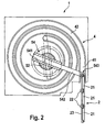
- the vertical sections 31 and 41 each open into a spiral section 32 or 42 in the form of a round spiral, in which the door leaf 2 is received in the open position of the roller shutter 1 in such a way that the individual lamellae 21 are in contact with each other in a spiral winding.
- the movement of the door leaf 2 between its end positions is effected by a drive 5.
- This has a motor 51, here an angle motor, which is received in the region of the lintel in the region of a side frame and is coupled there directly to a drive shaft 52.
- the drive shaft 52 passes through the spiral section 32 or 42 of the guides 3 and 4 in a central region.
- cantilever arms 53 and 54 are arranged on the drive shaft 52 on both sides of the door opening in each case adjacent to the spiral section 32 and 42.
- the extension arms 53 and 54 respectively pass through the drive shaft 52 centrally and project radially therefrom.
- each cantilever arm 53 and 54 a guide member 531 and 541, which is fixedly connected to the drive shaft 52.
- a piston part 532 and 542 is positively received and guided freely displaceable.
- a spaced from the guide member 531 and 541 present end of the piston member 532 and 542 and has a coupling point 533 and 543, by means of each arm 53 and 54 with the fall-side end of the Torblatts 2 is hinged.
- this is an over the entire gate width extending element (here in this first embodiment, a blade 21) before, whereby the driving force is transmitted uniformly on the Torblattbreite.
- Fig. 2 In the open position of the roller doors 1 are the extension arms 53 and 54 in the dashed lines in Fig. 2 shown position, from which it can be seen that their effective lever length compared to the excellent initial state has significantly reduced. How out Fig. 2 Furthermore, it can be seen that the length of the piston member 532 or 542 is selected such that it does not project beyond the other end of the associated guide member even in the maximum inserted state in the guide member 531 or 541, that it conflicts with a winding of the door leaf 2 in the spiral section 32 and 42 passes.
- the roller shutter 1 has a in the Fig. 1 to 3 not shown weight balancing device, which is formed in this embodiment in a conventional manner. This supports the drive 5 just at the beginning of the opening movement due to their spring bias, so that the forces to be introduced here by the drive 5 are comparatively low.
- the length of the door leaf 2 is selected such that the coupling points 533 and 543 are present in the closed position of the door leaf 2 at the entrance to the spiral section 32 and 42 and the boom arms 53 and 54 thus not as in Fig. 2 represented an attack angle of more than 90 ° to the door leaf 2 have, but in all areas of movement substantially perpendicular to the associated torrel-side end of the door leaf 2 are present.
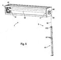
- Fig. 4 and 5 show a second embodiment of the present invention, which differs from the first embodiment in particular in the manner of coupling the cantilever arms 53 and 54 to the door leaf 2.
- Components of the rolling door 1 which correspond to those in the first embodiment are designated by the same reference numeral.
- the two end sections 24 are connected to one another over a transverse strut 25 over the entire door width.
- a roller 22 is also mounted on this.
- end portions 24 are formed in several parts, so that they are seen in their length in the direction of movement of the door leaf 2 adjustable. For a tolerance compensation is possible to avoid an inclination of the door leaf 2 in the side guides 3 and 4. In the embodiment shown this is made possible by an adjustable screw connection.
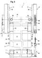
- a roller shutter 1 is explained below, which is designed as a lifting door and provided with a weight compensation device 6.
- Components of the rolling door 1, which correspond to those in the first embodiment are again denoted by the same reference number, with a detailed explanation of these features is omitted to avoid repetition.
- the lifting gate 1 on a weight compensation device 6, which includes a spring element 61, a tension member 62 and a winding device, a Guide means 63 and a shaft 64 has.
- the guide device 63 is mounted on the shaft 64.
- the shaft 64 is coupled directly to the drive shaft 52 and rotates with this in an operation of the motor 51 with.
- the spring element 61 has four coil springs 611 in the present embodiment, which are fixed on the bottom side. With their other end, the coil springs 611 are connected via a bracket 612 fixed to the tension element 62, which is designed here as a chain. The lintel-side end of the tension element 62 is deflected in the region of the lintel about a deflection roller 65 and is fastened to the guide device 63.
- the guide device 63 is shown together with the tension member 62 in more detail.
- the tension member 62 is wound without contact in the course of the closing movement of the door leaf 2 by means of the guide means 63.
- the tension member 62 is fixed to an attachment point 66 on the guide means 63 and extends in the wound state according to the dash-two-dotted line 67 according to Fig. 7 which describes the chain running center.
- the guide means 63 an inner guide portion 631, a first outer guide portion 632 and a second outer guide portion 633 on.
- the guide portions are formed so that they have circumferentially guide surfaces with a continuously growing in the winding direction radius.
- the two outer guide portions 632 and 633 are configured as a pair of disks 632a and 632b, and 633a and 633b, which axially enclose the inner guide portion 631, respectively.
- the second outer guide portion 633 further includes the first outer guide portion 632 axially.
- the maximum guide surface radius of the inner guide portion 631 corresponds to the minimum guide surface radius of the first outer guide portion 632, so that there is a smooth transition here.
- the maximum guide surface radius of the first outer guide portion 632 is configured corresponding to the minimum guide surface radius of the second outer guide portion 633.
- the pulling element 62 is thereby formed so that it has an increasing width in the direction of the bottom end of its fall-side end.
- the tension element 62 has three different widths corresponding to the number of guide sections.
- Fig. 11 For clarity, the chain is shown in a cut state as it comes to rest on the guide portions of the guide 63. It can be seen that the tension member 62 is thus wound without contact and without an axial displacement relative to the shaft 64 in the guide means 63.
- the width of the tension element 62 is selected at the fall end so that this section 62a can be wound directly onto the inner guide portion 631.
- a second portion 62b of the tension member 62 having a mean width corresponds to the width of the first outer guide portion 632, so that this portion 62b of the tension member 62 is wound on the guide surfaces thereof.
- the width of a subsequent spread portion 62 c of the tension member 62 is adapted to the width of the second outer guide portion 633 so as to come to rest on the guide surfaces thereof.
- Fig. 13 is schematically illustrated by characteristics of the characteristic of the weight balancer 6.
- an exemplary gate height of 6 m is shown, to the right, the respective clear height of the remaining door opening is applied.
- the value "0.00” thus stands for the fully closed lifting gate 1
- the value "6.00” stands for the fully opened lifting gate 1.
- the torque acting on the drive shaft 52 is given based on the weight of the free door leaf section with a curve 81 through the diamonds, while the moment acting on the drive shaft 52 by the weight balancer 6 is indicated by a curve 82 passing through the squares , It indicates the moment caused by the spring element 61.
- the weight compensation device 6 is set so that when the door is closed, the spring element 61 is stretched so far that an excess of the torque produced by the weight of the door leaf torque excess of about 200 Nm is present.
- the closed lifting gate 1 is actuated, the door leaf 2 ascends upwards to approximately that height without additional drive, in which the weight force of the free door leaf section is in equilibrium with the applied spring force of the spring element 61 Fig. 13 this is a place where the two lines intersect, ie at a height of about 2.5 m.
- the invention allows for even more design approaches.
- the distance between the coupling points 533 and 543 of the cantilever arms 53 and 54 on the door leaf 2 and the pivot axis of the cantilever arms 53 and 54 is changed in any other way than by a telescopic design of the cantilever arms.
- the cantilever arms may also have a predetermined length, in which case elements in the region of the coupling points are mounted so as to be longitudinally displaceable on the cantilever arms.
- Such a design is particularly conceivable when the cantilever arms are seen in gate width outside of the guides 3 and 4 are arranged for the door leaf 2 and the coupling member 32 passes through the spiral portion 42. In this case, the overall length of the cantilever arms of minor importance, since a collision with turns of the door leaf 2 in the spiral section 32 and 42 can not occur.
- the extension arms can also be designed to be telescopically two or more times.
- the total length of the piston part can be reduced, whereby any conflicts with turns of the door leaf 2 in the open position can be even better avoided.
- the piston member is guided freely displaceable in the tubular guide member.
- the guide member also need not be tubular, but may, for example, a polygonal, possibly open on one side cross-sectional shape, as long as the piston member is guided therein reliably and form-liquid.
- the cross-sectional shape of the guide part or of the piston part guided therein must be neither circular nor polygonal in a certain way. An oval configuration of the cross section or a combination of different cross-sectional shapes is also possible.
- the cantilever arms 53 and 54 need not be arranged on a common drive shaft; Instead, on both sides of the door opening coaxially mounted drive shaft sections may be present, to each of which a boom is coupled.
- the weight compensating device 6 can also be mounted on a separate bearing shaft.
- the motor 51, the drive shaft 52 or the drive shaft sections and / or the counterbalance device 6 does not drive directly, but indirectly via timing belt, chains, gear, etc. With regard to a compact arrangement as possible, however, is a direct drive of these components preferable.
- roller door 1 essentially irrelevant, which type of door leaf 2 is present.
- the inventively provided force on the lintel end of the door leaf 2 can be equally for lamellar armor, mounted in frame flexible hangings, door leaves as in the DE 102 36 648 A1 described, etc. apply.
- such a weight compensation device in all the illustrated embodiments.
- such may also be arranged in both lateral frames. In particular, with door leaves with larger widths, this can be advantageous to reduce one-sided loads on the arrangement.
- the number of coil springs 611 of the spring element 61 is determined by the given loads, i. H. in particular according to the type of door leaf, its weight and its dimensions.
- the tension element 62 does not have to be configured as a chain, but may also be present in the form of a ribbon.
- a dimensionally stable material in particular a metal is preferable.
- the number of guide sections on the guide device 63 depends on the length of the tension element 62 and thus indirectly on the door height. Accordingly, more or less than the described three guide sections can be given.
- a guide device which has two guide spirals, which extend from a central portion with increasing radius axially further away from each other to the outside.
- This embodiment is particularly suitable in connection with a continuous or at least quasi-continuous from the end facing the winding device to the end facing the spring element in width widening tension element, which can be wound directly contactless and free of axial displacement thereon.
- the tension element is preferably formed as a band.
- Tolerance compensation by adjusting the distance between the door leaf and the coupling points of the cantilever arms can also be done in other ways than through the multi-part end portions 24.
- other devices can take over this function, if such end portions should not be given in one embodiment.
Landscapes
- Engineering & Computer Science (AREA)
- Structural Engineering (AREA)
- Architecture (AREA)
- Civil Engineering (AREA)
- Operating, Guiding And Securing Of Roll- Type Closing Members (AREA)
- Power-Operated Mechanisms For Wings (AREA)
- Rollers For Roller Conveyors For Transfer (AREA)
- Forklifts And Lifting Vehicles (AREA)
- Elevator Door Apparatuses (AREA)
Priority Applications (2)
| Application Number | Priority Date | Filing Date | Title |
|---|---|---|---|
| PL06806310T PL1948898T3 (pl) | 2005-10-17 | 2006-10-16 | Szybkobieżna przemysłowa brama rolowana |
| SI200630580T SI1948898T1 (sl) | 2005-10-17 | 2006-10-16 | Hitro tekoŽŤa industrijska navijalna vrata |
Applications Claiming Priority (2)
| Application Number | Priority Date | Filing Date | Title |
|---|---|---|---|
| DE102005049584A DE102005049584A1 (de) | 2005-10-17 | 2005-10-17 | Schnellaufendes Industrierolltor |
| PCT/EP2006/009974 WO2007045423A1 (de) | 2005-10-17 | 2006-10-16 | Schnellaufendes industrierolltor |
Publications (2)
| Publication Number | Publication Date |
|---|---|
| EP1948898A1 EP1948898A1 (de) | 2008-07-30 |
| EP1948898B1 true EP1948898B1 (de) | 2009-12-09 |
Family
ID=37460259
Family Applications (1)
| Application Number | Title | Priority Date | Filing Date |
|---|---|---|---|
| EP06806310A Active EP1948898B1 (de) | 2005-10-17 | 2006-10-16 | Schnellaufendes industrierolltor |
Country Status (13)
| Country | Link |
|---|---|
| US (1) | US7913739B2 (pl) |
| EP (1) | EP1948898B1 (pl) |
| JP (1) | JP4847536B2 (pl) |
| CN (1) | CN101326337B (pl) |
| AT (1) | ATE451535T1 (pl) |
| DE (2) | DE102005049584A1 (pl) |
| DK (1) | DK1948898T3 (pl) |
| ES (1) | ES2337928T3 (pl) |
| PL (1) | PL1948898T3 (pl) |
| PT (1) | PT1948898E (pl) |
| RU (1) | RU2378474C1 (pl) |
| SI (1) | SI1948898T1 (pl) |
| WO (1) | WO2007045423A1 (pl) |
Families Citing this family (33)
| Publication number | Priority date | Publication date | Assignee | Title |
|---|---|---|---|---|
| DE102005049585B3 (de) * | 2005-10-17 | 2007-07-19 | Efaflex Inzeniring D.O.O. | Gewichtsausgleichseinrichtung für ein Hubtor |
| DE102006018637B4 (de) * | 2006-04-21 | 2011-05-12 | Manfred Seysen | Schnelllauftor |
| DE102008007592A1 (de) | 2008-02-06 | 2009-08-13 | Efaflex Tor- Und Sicherheitssysteme Gmbh & Co. Kg | Hubtoranordnung sowie Torsturz-Abdichteinrichtung hierfür |
| DE202008013474U1 (de) | 2008-10-14 | 2008-12-18 | Efaflex Tortechnik Gmbh | Rolltor |
| DE102009044492B8 (de) | 2009-11-10 | 2012-03-01 | Efaflex Inženiring D. O. O. Ljubljana | Rolltor, insbesondere schnelllaufendes Industrietor |
| DE102010000556A1 (de) | 2010-02-25 | 2011-08-25 | Efaflex Inzeniring D.O.O. Ljubljana | Hubtor mit einer beweglichen Torblattführung |
| DE102011052304A1 (de) | 2011-07-29 | 2013-01-31 | Efaflex Inzeniring D.O.O. | Hubtor mit einer beweglichen Torblattführung |
| CN103015876A (zh) * | 2012-12-28 | 2013-04-03 | 青岛巴士德工业门制造有限公司 | 一种硬质螺旋快速门 |
| CN103337222B (zh) * | 2013-07-01 | 2015-07-08 | 京东方科技集团股份有限公司 | 柔性显示装置 |
| DE102014005578A1 (de) * | 2014-04-15 | 2015-10-15 | Seuster Kg | Tor |
| US10344527B2 (en) | 2014-11-21 | 2019-07-09 | Asi Doors, Inc. | Roll-up door |
| DE102015004859A1 (de) * | 2015-04-17 | 2016-10-20 | Eric Blumenstiel | Rollladen |
| DE102015112633B4 (de) * | 2015-07-31 | 2017-04-13 | EFAFLEX INŽENIRING d.o.o. Ljubljana | Rolltoranordnung ohne Polygoneffekt |
| SI3263820T1 (sl) * | 2016-06-28 | 2019-02-28 | Gabrijel Rejc | Motorno gnana in navpično premična dvižna vrata |
| EP3263819B1 (de) * | 2016-06-28 | 2018-12-19 | Gabrijel Rejc | Vertikal bewegbares tor mit einem torblatt |
| US20180156577A1 (en) * | 2016-12-02 | 2018-06-07 | Ballistic Cordon Systems, LLC | Ballistic Curtain Cordon System |
| DE102016225079A1 (de) | 2016-12-15 | 2018-06-21 | Gabrijel Rejc Gmbh & Co. Kg | Tor mit einer Absturzsicherung |
| SI3805513T1 (sl) * | 2017-05-31 | 2023-10-30 | Seuster Kg | Navijalna vrata |
| DE102017118959A1 (de) * | 2017-08-18 | 2019-02-21 | Seuster Kg | Tor, insbesondere Spiraltor |
| US11162301B2 (en) * | 2017-09-07 | 2021-11-02 | Overhead Door Corporation | Roll-up door with spiral brackets |
| USD896616S1 (en) | 2018-03-22 | 2020-09-22 | Clopay Building Products Company, Inc. | Garage door cam |
| USD855438S1 (en) | 2018-03-22 | 2019-08-06 | Clopay Building Products Company, Inc. | Garage door cam |
| ES2952747T3 (es) * | 2018-04-05 | 2023-11-03 | Seuster Kg | Puerta con disposición de guiado |
| US11105133B2 (en) | 2018-04-17 | 2021-08-31 | Clopay Building Products Company, Inc. | High-speed sectional door |
| DE102018117320A1 (de) * | 2018-07-18 | 2020-01-23 | Seuster Kg | Tor |
| US12577832B2 (en) * | 2020-03-12 | 2026-03-17 | Assa Abloy Entrance Systems Ab | Door operation system |
| DE102022117999A1 (de) * | 2021-08-11 | 2023-03-16 | Magna Closures Inc. | Kraftbetätigtes einziehbares Verschlusspaneel für Lkw-Ladefläche |
| US20230051109A1 (en) * | 2021-08-12 | 2023-02-16 | JDS Industries | Retractable container cover |
| CN113503124B (zh) * | 2021-09-08 | 2021-11-19 | 南通四维幕墙装饰装潢有限责任公司 | 一种带隔热结构的卷帘门 |
| US12528642B2 (en) * | 2022-05-13 | 2026-01-20 | JDS Industries | Slip linkages for retractable container covers |
| EP4306346B1 (en) * | 2022-07-15 | 2026-02-18 | Gi.Anso 4x4 Club S.A. | Cover assembly for truck bed |
| CN115444296A (zh) * | 2022-09-02 | 2022-12-09 | 付婷 | 一种智能伸缩淋浴门 |
| CN116446777B (zh) * | 2023-04-28 | 2024-08-30 | 东莞市歌声美实业有限公司 | 自动及手动双模式卷帘门 |
Family Cites Families (31)
| Publication number | Priority date | Publication date | Assignee | Title |
|---|---|---|---|---|
| DE255647C (pl) | ||||
| US812722A (en) * | 1905-05-29 | 1906-02-13 | John Cahill | Rolling door or shutter and means for operating the same. |
| US1183402A (en) * | 1915-12-15 | 1916-05-16 | George H Frothingham Company | Variable-counterweighted door. |
| US2912048A (en) * | 1953-09-01 | 1959-11-10 | Grau Jaime Colom | Blind arrangement |
| US3095922A (en) * | 1958-04-04 | 1963-07-02 | Overhead Door Corp | Counterbalance and stop means for upwardly acting closures |
| US3092170A (en) * | 1959-07-22 | 1963-06-04 | William L Ellis | Automatic door |
| JPS5933996A (ja) * | 1982-08-20 | 1984-02-24 | Hitachi Ltd | 2線平衡伝送路選択回路 |
| DE8226196U1 (de) * | 1982-09-17 | 1983-02-17 | Reflexa-Werke H.P. Albrecht GmbH & Co KG, 8871 Rettenbach | Rolladen |
| FR2584216A1 (fr) * | 1985-06-26 | 1987-01-02 | Fafournoux Olivier | Procede et dispositif de detection d'une effraction realisee par relevage direct d'un volet roulant et volet roulant pourvu de ce dispositif. |
| GB8624735D0 (en) * | 1986-10-15 | 1986-11-19 | Clark Door Ltd | Roller door assemblies |
| FR2621951A1 (fr) * | 1987-10-20 | 1989-04-21 | Roux Marcel | Dispositif permettant la fermeture et l'ouverture d'un store a l'horizontale |
| DE3904224C2 (de) | 1988-05-16 | 1997-02-06 | Fischer & Porter Gmbh | Dralldurchflußmeßgerät |
| US4947937A (en) * | 1989-03-24 | 1990-08-14 | Fas Industries, Inc. | Spring-operated tambour apparatus |
| DE4015215A1 (de) * | 1990-05-11 | 1991-11-14 | Efaflex Transport Lager | Hubtor mit einem lamellenpanzer in fuehrungsbahnen |
| DE4015214A1 (de) | 1990-05-11 | 1991-11-14 | Efaflex Transport Lager | Hubtor mit einem lamellenpanzer mit abwinkelbaren lamellen |
| US5484007A (en) * | 1990-05-11 | 1996-01-16 | Rejc; Gabrijel | Vertical lift gate with strip cladding in guideways |
| ATE241755T1 (de) * | 1994-04-29 | 2003-06-15 | Dynaco Internat | Abschlussvorrichtung mit flexiblem schirm |
| US5632317A (en) * | 1995-03-31 | 1997-05-27 | Overhead Door Corporation | Roll-up door |
| FR2733000B1 (fr) * | 1995-04-14 | 1997-06-27 | Simu | Perfectionnements aux dispositifs de fermeture a enroulement |
| JPH10121873A (ja) * | 1996-10-23 | 1998-05-12 | Hisahiro Igarashi | バランス式シャッタ及びそのバランス装置 |
| DE29804411U1 (de) | 1997-09-18 | 1998-06-18 | Lamsfuss, Norbert, 53604 Bad Honnef | Rolltor |
| US6085825A (en) * | 1998-08-21 | 2000-07-11 | Rom Corporation | Power-driven shutter assembly |
| JP3554917B2 (ja) * | 1999-06-29 | 2004-08-18 | 三和シヤッター工業株式会社 | シートシャッターおよび該シートシャッターに用いるガイドブロック |
| DE10011789A1 (de) * | 2000-03-13 | 2001-09-20 | Aktor Ind Gmbh | Rolltor mit aufwickelbaren Torblatt |
| NL1016983C1 (nl) * | 2000-08-17 | 2002-02-19 | Hubert Hunker | Schuinstaand rolluik. |
| DE10119240A1 (de) * | 2001-04-19 | 2002-10-31 | Efaflex Tor & Sicherheitssys | Industrietor, doppelwandige Lamelle für ein Industrietor sowie Verfahren zur Herstellung einer derartigen Lamelle |
| AUPS224902A0 (en) * | 2002-05-13 | 2002-06-13 | Ozroll Ip Pty Ltd | A shutter assembly |
| US6883577B2 (en) * | 2003-02-24 | 2005-04-26 | Albany International Corp. | Rollup door with rollable door leaf |
| JP4505199B2 (ja) * | 2003-04-02 | 2010-07-21 | 株式会社湯山製作所 | 薬剤棚のシャッター装置 |
| CN1202349C (zh) * | 2003-07-15 | 2005-05-18 | 史建刚 | 能斜向移动的卷帘门卷轴机构 |
| DE102005049585B3 (de) * | 2005-10-17 | 2007-07-19 | Efaflex Inzeniring D.O.O. | Gewichtsausgleichseinrichtung für ein Hubtor |
-
2005
- 2005-10-17 DE DE102005049584A patent/DE102005049584A1/de not_active Ceased
-
2006
- 2006-10-16 RU RU2008119471/03A patent/RU2378474C1/ru active
- 2006-10-16 DK DK06806310.6T patent/DK1948898T3/da active
- 2006-10-16 US US12/089,815 patent/US7913739B2/en active Active
- 2006-10-16 WO PCT/EP2006/009974 patent/WO2007045423A1/de not_active Ceased
- 2006-10-16 ES ES06806310T patent/ES2337928T3/es active Active
- 2006-10-16 SI SI200630580T patent/SI1948898T1/sl unknown
- 2006-10-16 DE DE502006005622T patent/DE502006005622D1/de active Active
- 2006-10-16 EP EP06806310A patent/EP1948898B1/de active Active
- 2006-10-16 PT PT06806310T patent/PT1948898E/pt unknown
- 2006-10-16 PL PL06806310T patent/PL1948898T3/pl unknown
- 2006-10-16 AT AT06806310T patent/ATE451535T1/de active
- 2006-10-16 CN CN2006800466452A patent/CN101326337B/zh active Active
- 2006-10-16 JP JP2008535950A patent/JP4847536B2/ja active Active
Also Published As
| Publication number | Publication date |
|---|---|
| ES2337928T3 (es) | 2010-04-30 |
| DE502006005622D1 (de) | 2010-01-21 |
| CN101326337B (zh) | 2013-05-15 |
| EP1948898A1 (de) | 2008-07-30 |
| DE102005049584A1 (de) | 2007-05-10 |
| CN101326337A (zh) | 2008-12-17 |
| SI1948898T1 (sl) | 2010-04-30 |
| PT1948898E (pt) | 2010-03-12 |
| US20080251220A1 (en) | 2008-10-16 |
| WO2007045423A1 (de) | 2007-04-26 |
| JP4847536B2 (ja) | 2011-12-28 |
| JP2009511792A (ja) | 2009-03-19 |
| DK1948898T3 (da) | 2010-04-12 |
| PL1948898T3 (pl) | 2010-05-31 |
| ATE451535T1 (de) | 2009-12-15 |
| RU2378474C1 (ru) | 2010-01-10 |
| US7913739B2 (en) | 2011-03-29 |
Similar Documents
| Publication | Publication Date | Title |
|---|---|---|
| EP1948898B1 (de) | Schnellaufendes industrierolltor | |
| EP1954909B1 (de) | Gewichtsausgleichseinrichtung für ein hubtor | |
| EP0806538B1 (de) | Motorisch angetriebener Fensterheber mit elektronischem Einklemmschutz für ein Kraftfahrzeug | |
| EP3263819B1 (de) | Vertikal bewegbares tor mit einem torblatt | |
| EP2737152B1 (de) | Hubtor mit einer beweglichen torblattführung | |
| EP1165926B1 (de) | Industrietor | |
| DE112004000483T5 (de) | Antriebssystem für Garagentor | |
| EP2614974B1 (de) | Rollosystem für ein Kraftfahrzeug | |
| EP2925947B1 (de) | Rolltor mit einem torblatt in gestalt eines flexiblen behangs | |
| EP1197627B1 (de) | Antrieb für Tore, insbesondere Garagentore | |
| EP1965018B1 (de) | Tor mit Zugfederausgleich sowie Antriebsvorrichtung hierfür | |
| EP2131003B1 (de) | Drehwellenanordnung für ein Tor, insbesondere für ein Rolltor, und ein solches Tor | |
| DE3245009A1 (de) | Rolltor | |
| EP0556632A2 (de) | Horizontal-Rolltor | |
| DE4327230C1 (de) | Rolladen für Dachfenster | |
| EP0930416B1 (de) | Rolltor | |
| DE102005057385B4 (de) | Rolltor | |
| DE202004019844U1 (de) | Fensterrollo für ein Fahrzeugfenster | |
| DE10350116B3 (de) | Rollabschluss | |
| DE10047372C1 (de) | Antrieb für Tore, insbesondere Garagentore | |
| DE20320336U1 (de) | Rolltor mit Kollisionsschutz | |
| DE102012107286B4 (de) | Rolltor mit einer Gegengewichtsausgleichsvorrichtung | |
| DE4314128A1 (de) | Fenster mit Sonnenschutzanlage für schräge Dachflächen | |
| DE202014102237U1 (de) | Vorrichtung zum Aufwickeln von Rollpanzern | |
| DE10348299A1 (de) | Kettentrieb und Betätigungsvorrichtung mit einem solchen Kettentrieb |
Legal Events
| Date | Code | Title | Description |
|---|---|---|---|
| PUAI | Public reference made under article 153(3) epc to a published international application that has entered the european phase |
Free format text: ORIGINAL CODE: 0009012 |
|
| 17P | Request for examination filed |
Effective date: 20080519 |
|
| AK | Designated contracting states |
Kind code of ref document: A1 Designated state(s): AT BE BG CH CY CZ DE DK EE ES FI FR GB GR HU IE IS IT LI LT LU LV MC NL PL PT RO SE SI SK TR |
|
| GRAP | Despatch of communication of intention to grant a patent |
Free format text: ORIGINAL CODE: EPIDOSNIGR1 |
|
| DAX | Request for extension of the european patent (deleted) | ||
| GRAS | Grant fee paid |
Free format text: ORIGINAL CODE: EPIDOSNIGR3 |
|
| GRAA | (expected) grant |
Free format text: ORIGINAL CODE: 0009210 |
|
| AK | Designated contracting states |
Kind code of ref document: B1 Designated state(s): AT BE BG CH CY CZ DE DK EE ES FI FR GB GR HU IE IS IT LI LT LU LV MC NL PL PT RO SE SI SK TR |
|
| REG | Reference to a national code |
Ref country code: GB Ref legal event code: FG4D Free format text: NOT ENGLISH |
|
| REG | Reference to a national code |
Ref country code: CH Ref legal event code: EP |
|
| REG | Reference to a national code |
Ref country code: IE Ref legal event code: FG4D |
|
| REF | Corresponds to: |
Ref document number: 502006005622 Country of ref document: DE Date of ref document: 20100121 Kind code of ref document: P |
|
| REG | Reference to a national code |
Ref country code: PT Ref legal event code: SC4A Free format text: AVAILABILITY OF NATIONAL TRANSLATION Effective date: 20100305 |
|
| REG | Reference to a national code |
Ref country code: CH Ref legal event code: NV Representative=s name: KELLER & PARTNER PATENTANWAELTE AG |
|
| REG | Reference to a national code |
Ref country code: SE Ref legal event code: TRGR |
|
| REG | Reference to a national code |
Ref country code: NL Ref legal event code: T3 |
|
| REG | Reference to a national code |
Ref country code: DK Ref legal event code: T3 |
|
| REG | Reference to a national code |
Ref country code: GR Ref legal event code: EP Ref document number: 20100400572 Country of ref document: GR |
|
| PG25 | Lapsed in a contracting state [announced via postgrant information from national office to epo] |
Ref country code: LT Free format text: LAPSE BECAUSE OF FAILURE TO SUBMIT A TRANSLATION OF THE DESCRIPTION OR TO PAY THE FEE WITHIN THE PRESCRIBED TIME-LIMIT Effective date: 20091209 |
|
| REG | Reference to a national code |
Ref country code: ES Ref legal event code: FG2A Ref document number: 2337928 Country of ref document: ES Kind code of ref document: T3 |
|
| LTIE | Lt: invalidation of european patent or patent extension |
Effective date: 20091209 |
|
| PG25 | Lapsed in a contracting state [announced via postgrant information from national office to epo] |
Ref country code: LV Free format text: LAPSE BECAUSE OF FAILURE TO SUBMIT A TRANSLATION OF THE DESCRIPTION OR TO PAY THE FEE WITHIN THE PRESCRIBED TIME-LIMIT Effective date: 20091209 |
|
| REG | Reference to a national code |
Ref country code: PL Ref legal event code: T3 |
|
| REG | Reference to a national code |
Ref country code: HU Ref legal event code: AG4A Ref document number: E007503 Country of ref document: HU |
|
| PG25 | Lapsed in a contracting state [announced via postgrant information from national office to epo] |
Ref country code: IS Free format text: LAPSE BECAUSE OF FAILURE TO SUBMIT A TRANSLATION OF THE DESCRIPTION OR TO PAY THE FEE WITHIN THE PRESCRIBED TIME-LIMIT Effective date: 20100409 Ref country code: BG Free format text: LAPSE BECAUSE OF FAILURE TO SUBMIT A TRANSLATION OF THE DESCRIPTION OR TO PAY THE FEE WITHIN THE PRESCRIBED TIME-LIMIT Effective date: 20100309 Ref country code: RO Free format text: LAPSE BECAUSE OF FAILURE TO SUBMIT A TRANSLATION OF THE DESCRIPTION OR TO PAY THE FEE WITHIN THE PRESCRIBED TIME-LIMIT Effective date: 20091209 Ref country code: EE Free format text: LAPSE BECAUSE OF FAILURE TO SUBMIT A TRANSLATION OF THE DESCRIPTION OR TO PAY THE FEE WITHIN THE PRESCRIBED TIME-LIMIT Effective date: 20091209 |
|
| PG25 | Lapsed in a contracting state [announced via postgrant information from national office to epo] |
Ref country code: SK Free format text: LAPSE BECAUSE OF FAILURE TO SUBMIT A TRANSLATION OF THE DESCRIPTION OR TO PAY THE FEE WITHIN THE PRESCRIBED TIME-LIMIT Effective date: 20091209 |
|
| PLBE | No opposition filed within time limit |
Free format text: ORIGINAL CODE: 0009261 |
|
| STAA | Information on the status of an ep patent application or granted ep patent |
Free format text: STATUS: NO OPPOSITION FILED WITHIN TIME LIMIT |
|
| PG25 | Lapsed in a contracting state [announced via postgrant information from national office to epo] |
Ref country code: CY Free format text: LAPSE BECAUSE OF FAILURE TO SUBMIT A TRANSLATION OF THE DESCRIPTION OR TO PAY THE FEE WITHIN THE PRESCRIBED TIME-LIMIT Effective date: 20091209 |
|
| 26N | No opposition filed |
Effective date: 20100910 |
|
| PG25 | Lapsed in a contracting state [announced via postgrant information from national office to epo] |
Ref country code: MC Free format text: LAPSE BECAUSE OF NON-PAYMENT OF DUE FEES Effective date: 20101031 |
|
| REG | Reference to a national code |
Ref country code: CH Ref legal event code: PCAR Free format text: NEW ADDRESS: EIGERSTRASSE 2 POSTFACH, 3000 BERN 14 (CH) |
|
| REG | Reference to a national code |
Ref country code: FR Ref legal event code: PLFP Year of fee payment: 10 |
|
| REG | Reference to a national code |
Ref country code: FR Ref legal event code: PLFP Year of fee payment: 11 |
|
| REG | Reference to a national code |
Ref country code: FR Ref legal event code: PLFP Year of fee payment: 12 |
|
| REG | Reference to a national code |
Ref country code: FR Ref legal event code: PLFP Year of fee payment: 13 |
|
| REG | Reference to a national code |
Ref country code: CH Ref legal event code: PFA Owner name: EFAFLEX INZENIRING D.O.O. LJUBLJANA, SI Free format text: FORMER OWNER: EFAFLEX INZENIRING D.O.O. LJUBLJANA, SI |
|
| PGFP | Annual fee paid to national office [announced via postgrant information from national office to epo] |
Ref country code: NL Payment date: 20241023 Year of fee payment: 19 |
|
| PGFP | Annual fee paid to national office [announced via postgrant information from national office to epo] |
Ref country code: LU Payment date: 20241022 Year of fee payment: 19 |
|
| PGFP | Annual fee paid to national office [announced via postgrant information from national office to epo] |
Ref country code: HU Payment date: 20241011 Year of fee payment: 19 |
|
| PGFP | Annual fee paid to national office [announced via postgrant information from national office to epo] |
Ref country code: PT Payment date: 20241014 Year of fee payment: 19 |
|
| PGFP | Annual fee paid to national office [announced via postgrant information from national office to epo] |
Ref country code: DK Payment date: 20241023 Year of fee payment: 19 |
|
| PGFP | Annual fee paid to national office [announced via postgrant information from national office to epo] |
Ref country code: FI Payment date: 20241022 Year of fee payment: 19 Ref country code: BE Payment date: 20241022 Year of fee payment: 19 Ref country code: GR Payment date: 20241021 Year of fee payment: 19 Ref country code: PL Payment date: 20241003 Year of fee payment: 19 |
|
| PGFP | Annual fee paid to national office [announced via postgrant information from national office to epo] |
Ref country code: GB Payment date: 20241024 Year of fee payment: 19 |
|
| PGFP | Annual fee paid to national office [announced via postgrant information from national office to epo] |
Ref country code: FR Payment date: 20241024 Year of fee payment: 19 Ref country code: AT Payment date: 20241021 Year of fee payment: 19 |
|
| PGFP | Annual fee paid to national office [announced via postgrant information from national office to epo] |
Ref country code: IE Payment date: 20241018 Year of fee payment: 19 |
|
| PGFP | Annual fee paid to national office [announced via postgrant information from national office to epo] |
Ref country code: IT Payment date: 20241031 Year of fee payment: 19 Ref country code: ES Payment date: 20241118 Year of fee payment: 19 |
|
| PGFP | Annual fee paid to national office [announced via postgrant information from national office to epo] |
Ref country code: SE Payment date: 20241023 Year of fee payment: 19 |
|
| PGFP | Annual fee paid to national office [announced via postgrant information from national office to epo] |
Ref country code: CH Payment date: 20241101 Year of fee payment: 19 |
|
| PGFP | Annual fee paid to national office [announced via postgrant information from national office to epo] |
Ref country code: TR Payment date: 20241009 Year of fee payment: 19 |
|
| PGFP | Annual fee paid to national office [announced via postgrant information from national office to epo] |
Ref country code: SI Payment date: 20241003 Year of fee payment: 19 |
|
| PGFP | Annual fee paid to national office [announced via postgrant information from national office to epo] |
Ref country code: DE Payment date: 20251020 Year of fee payment: 20 |
|
| PGFP | Annual fee paid to national office [announced via postgrant information from national office to epo] |
Ref country code: CZ Payment date: 20251003 Year of fee payment: 20 |