EP1947616B1 - Sicherheitsvorrichtung zum Steuern des Betriebs der Funktionsausrüstung mit beweglichen Teilen - Google Patents
Sicherheitsvorrichtung zum Steuern des Betriebs der Funktionsausrüstung mit beweglichen Teilen Download PDFInfo
- Publication number
- EP1947616B1 EP1947616B1 EP08152917.4A EP08152917A EP1947616B1 EP 1947616 B1 EP1947616 B1 EP 1947616B1 EP 08152917 A EP08152917 A EP 08152917A EP 1947616 B1 EP1947616 B1 EP 1947616B1
- Authority
- EP
- European Patent Office
- Prior art keywords
- camera
- markings
- signal
- operating unit
- pixels
- Prior art date
- Legal status (The legal status is an assumption and is not a legal conclusion. Google has not performed a legal analysis and makes no representation as to the accuracy of the status listed.)
- Expired - Lifetime
Links
- 0 CCC(C)C1(C2C(C(CC3(*)C4)C3IC4(CIC)I**=C)ICC2*C)C(CC)C(*)CCC1 Chemical compound CCC(C)C1(C2C(C(CC3(*)C4)C3IC4(CIC)I**=C)ICC2*C)C(CC)C(*)CCC1 0.000 description 2
Images


Classifications
-
- G—PHYSICS
- G07—CHECKING-DEVICES
- G07F—COIN-FREED OR LIKE APPARATUS
- G07F7/00—Mechanisms actuated by objects other than coins to free or to actuate vending, hiring, coin or paper currency dispensing or refunding apparatus
- G07F7/06—Mechanisms actuated by objects other than coins to free or to actuate vending, hiring, coin or paper currency dispensing or refunding apparatus by returnable containers, i.e. reverse vending systems in which a user is rewarded for returning a container that serves as a token of value, e.g. bottles
- G07F7/0609—Mechanisms actuated by objects other than coins to free or to actuate vending, hiring, coin or paper currency dispensing or refunding apparatus by returnable containers, i.e. reverse vending systems in which a user is rewarded for returning a container that serves as a token of value, e.g. bottles by fluid containers, e.g. bottles, cups, gas containers
-
- G—PHYSICS
- G01—MEASURING; TESTING
- G01N—INVESTIGATING OR ANALYSING MATERIALS BY DETERMINING THEIR CHEMICAL OR PHYSICAL PROPERTIES
- G01N21/00—Investigating or analysing materials by the use of optical means, i.e. using sub-millimetre waves, infrared, visible or ultraviolet light
- G01N21/84—Systems specially adapted for particular applications
- G01N21/88—Investigating the presence of flaws or contamination
- G01N21/8806—Specially adapted optical and illumination features
-
- Y—GENERAL TAGGING OF NEW TECHNOLOGICAL DEVELOPMENTS; GENERAL TAGGING OF CROSS-SECTIONAL TECHNOLOGIES SPANNING OVER SEVERAL SECTIONS OF THE IPC; TECHNICAL SUBJECTS COVERED BY FORMER USPC CROSS-REFERENCE ART COLLECTIONS [XRACs] AND DIGESTS
- Y02—TECHNOLOGIES OR APPLICATIONS FOR MITIGATION OR ADAPTATION AGAINST CLIMATE CHANGE
- Y02W—CLIMATE CHANGE MITIGATION TECHNOLOGIES RELATED TO WASTEWATER TREATMENT OR WASTE MANAGEMENT
- Y02W30/00—Technologies for solid waste management
- Y02W30/50—Reuse, recycling or recovery technologies
- Y02W30/60—Glass recycling
-
- Y—GENERAL TAGGING OF NEW TECHNOLOGICAL DEVELOPMENTS; GENERAL TAGGING OF CROSS-SECTIONAL TECHNOLOGIES SPANNING OVER SEVERAL SECTIONS OF THE IPC; TECHNICAL SUBJECTS COVERED BY FORMER USPC CROSS-REFERENCE ART COLLECTIONS [XRACs] AND DIGESTS
- Y02—TECHNOLOGIES OR APPLICATIONS FOR MITIGATION OR ADAPTATION AGAINST CLIMATE CHANGE
- Y02W—CLIMATE CHANGE MITIGATION TECHNOLOGIES RELATED TO WASTEWATER TREATMENT OR WASTE MANAGEMENT
- Y02W30/00—Technologies for solid waste management
- Y02W30/50—Reuse, recycling or recovery technologies
- Y02W30/62—Plastics recycling; Rubber recycling
-
- Y—GENERAL TAGGING OF NEW TECHNOLOGICAL DEVELOPMENTS; GENERAL TAGGING OF CROSS-SECTIONAL TECHNOLOGIES SPANNING OVER SEVERAL SECTIONS OF THE IPC; TECHNICAL SUBJECTS COVERED BY FORMER USPC CROSS-REFERENCE ART COLLECTIONS [XRACs] AND DIGESTS
- Y10—TECHNICAL SUBJECTS COVERED BY FORMER USPC
- Y10S—TECHNICAL SUBJECTS COVERED BY FORMER USPC CROSS-REFERENCE ART COLLECTIONS [XRACs] AND DIGESTS
- Y10S209/00—Classifying, separating, and assorting solids
- Y10S209/919—Rotary feed conveyor
-
- Y—GENERAL TAGGING OF NEW TECHNOLOGICAL DEVELOPMENTS; GENERAL TAGGING OF CROSS-SECTIONAL TECHNOLOGIES SPANNING OVER SEVERAL SECTIONS OF THE IPC; TECHNICAL SUBJECTS COVERED BY FORMER USPC CROSS-REFERENCE ART COLLECTIONS [XRACs] AND DIGESTS
- Y10—TECHNICAL SUBJECTS COVERED BY FORMER USPC
- Y10S—TECHNICAL SUBJECTS COVERED BY FORMER USPC CROSS-REFERENCE ART COLLECTIONS [XRACs] AND DIGESTS
- Y10S209/00—Classifying, separating, and assorting solids
- Y10S209/93—Municipal solid waste sorting
Definitions
- the present invention is related in general to apparatus for handling items or objects, e.g. for receiving, sorting and storing returnable items or objects, such as empty beverage containers like bottles, cans or the like.
- the invention is particularly useful in connection with reverse vending machines, although certain aspects of the present invention may also find other fields of use.
- the present invention relates to a safety apparatus for controlling operation of functional equipment having movable parts, said apparatus configured to use a camera to view and cause detection of a safety related event in a field of view of the camera.
- RVMs reverse vending machines
- back-room systems that are capable of receiving and storing used containers have been quite complex and expensive. They have, therefore, mostly been found in larger stores, shopping centers or supermarkets, or in special facilities put up for collecting recyclable items or objects.
- the currently available reverse vending machines normally deliver the received objects to a back-room receiving facility or a downstairs facility.
- the total installation is expensive, requires substantial space, is often complex to install and service, and has operational drawbacks, in particular from a cleaning point of view. Frequent cleaning of soiled operational parts, suitably with water or special cleaning agent, is very important to secure failsafe operation.
- Returnable beverage containers frequently contain beverage leftovers, which often happen to come into contact with operational parts, thus making such parts sticky and causing operational failure if not properly cleaned. Cleaning is more than often a messy operation, and care has to be made not to harm electrical components.
- RVMs need to have the ability to inspect identifying features on the object, such as e.g. a bar code. If such features are not immediately seen by a dedicated detector, the object will need to be rotated to find if such features are indeed present.
- An object rotating mechanism is expensive and requires substantial space in the longitudinal or depth direction of the RVM.
- an additional sorter has to be provided, adding further to the cost of the installation, and the dimension of the RVM as regards depth dimension is in some cases prohibitive when both a rotator and a sorter are to be included.
- EP 1262905 discloses a device that has transmitter, receiver and analysis unit for evaluation of the output signal from the receiver. Light beams from the transmitter are deflected using a deflection unit so that they are displaced relative to each other to form a number of separate scanning lines forming partial monitoring areas. When an object enters a partial scanning area an object identification signal is generated with the individual signals combined into an output signal in the analysis unit.
- the present invention therefore has as a principal object to meet a long felt need to provide an improved automated facility for collecting returnable objects or items, such as recyclable items of plastic, metal or glass, and for overcoming the well-known mentioned drawbacks, thus yielding a low cost facility which exhibits optimal use of limited space, in particular floor space, that may be available almost everywhere, enabling their placement even in smaller stores, convenience stores, local gas stations and public areas. Thereby, such facilities may be more conveniently available to customers.
- Such a device is intended to enable camera viewing of two regions of an object, in order to subsequently enable processing of signals related to viewed features.
- such camera viewing can be of a location where the object can be placed and thereby cause subsequent recognition of the contour of the object, a lens being arranged between the camera and said location.
- the device enables use of a single camera.
- a device using a camera to view characteristic features of an object against a light providing or bright background area, in order to subsequently enable processing related to viewed features.
- a reverse vending machine In a reverse vending machine (RVM), it is conventional to view and recognize shape of the object at one location in the RVM and to recognize other identifiable characteristic features such as indicia, barcode etc. at another location. If e.g. a barcode is not directly visible to a barcode reader, the object must be rotated until the barcode becomes visible and can be read by the reader.
- RVM reverse vending machine
- US 5 934 440 discloses a device with a detection station for reading barcode, rotation of the object such as e.g. a bottle to locate a barcode not immediately visible, as well as a sorting function.
- a detection station for reading barcode, rotation of the object such as e.g. a bottle to locate a barcode not immediately visible, as well as a sorting function.
- the possibility of detecting an object contour at such station is not available and needs to be performed by a separate station suitably located upstream, as disclosed in said patent.
- the present disclosure also describes a device which makes use of camera aid to provide for major detection functions, and with other benefits resulting from the overall structure.
- the present invention relates to a safety apparatus for controlling operation of functional equipment having movable parts.
- RVM reverse vending machine It is a well-known technique in a reverse vending machine (RVM) to provide movement detectors or light curtains in the form of transmitter/ receiver pairs to detect when an object has reached a particular position in the RVM , to alert if someone tries to move a hand into the RVM, or to view a video image to detect entry into or direction of movement into a detection region as seen by a camera. Upon such detection, action can be taken to inhibit further operation of moving parts and/ or trigger an alarm. Further, in the case of transmitter/ receiver pairs, expensive hardware has to be installed, aligned and serviced.
- European Patent EP-0910485 discloses a camera functionality in order to control movements in a camera field of view in connection with a reverse vending machine. Such movement control is software related.
- any software update related to camera function must also be documented and certified to ensure that said monitoring capability is still operative. Such process is time consuming and expensive.
- the image may appear blank as if no activity or events in the camera field of view would be present. In such a situation, an inherent safety hazard may be present.
- Safety hazards e.g. include the risk of a person getting a hand injured if put into the RVM, or operational failures due to incorrect handling of the RVM by a person.
- the invention has therefore as an object to avoid the inherent drawbacks of the prior art solutions related to avoiding safety hazards.
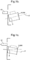
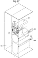
- Fig. 1a illustrates in an exemplary embodiment a reverse vending machine (RVM) 1 embodying main inventive aspects of the present invention, i.e. object storage chamber 2; object supporting, rotating, sorting and conveyor unit 3; camera-aided detector device 4; supplementary item/ object collector means 5; token dispenser 6; token reader 7, safety apparatus 8, and drive means 9; 9'.
- the unit 3 (later denoted as 200) could have to have its longitudinal axis 3' horizontal or forming an angle ⁇ with the horizontal, yielding angle ⁇ in the range ⁇ 0° - 30°, as indicated on figs. 1b and 1c .
- the operational means 2-9 just mentioned will for practical reasons be denoted by other reference numerals.
- Direction is also made to fig. 17 showing the figure of fig. 1a , however with more reference numerals inserted to identify location of some of the various operational means which are extensively disclosed in the disclosure to follow in connection with figs. 2-16 .
- Figs. 2-13 show embodiments of a camera system implemented in a RVM. These embodiments are helpful for understanding the invention and possible implementations of the invention.
- Fig. 2 depicts a first light source 300 and a second light source 301, the light source 301 suitably consisting of a plurality of light sub-sources 302, 303, 304, 305.
- the light sources 300 and 301 are separately configured to illuminate a first region 306 and a second region 307 of an object, e.g. a returnable item 10, 10', 10", 10"'.
- a single camera 308 is provided to view at least part of the regions 306 and 307.
- the first light source 300 is configured to assist the camera 308 in viewing of contour of objects, items or articles 10, 10', 10", 10''' of different cross section, e.g. empty beverage packaging such as cans and bottles against a light reflective area or background 313 forming a bright, light emitting background.
- the light from the first light source 300 is directed towards the object (e,g. one of those labeled 10 through 10"' ) as parallel light using a lens 314.
- the second light source 301 is configured to assist camera viewing by the camera 308 for detection and recognition of any identity features located on the object in viewing sector labeled 315.
- Said identity features are suitably at least one of: bar code, graphic symbol and alphanumeric characters.
- the invention also offers a substantial advantage over a two-camera solution.
- the camera sensor matrix When a camera views e.g. an object contour or identifying features thereon, the camera sensor matrix provides a string of matrix pixel signals to be processed in order to identify or recognize such contour or features, including the possibility of letting the camera read and causing identification of e.g. a bar code.
- the first light source 300 illuminates the first region 306 via a light path which includes an optical beam splitter (or view splitter) 316 ( figs. 2 and 3 ), 318 ( fig. 4 ) or 319 ( fig. 5 ), at least one inclined mirror 320 and the lens 314.
- an optical beam splitter or view splitter
- 316 figs. 2 and 3
- 318 fig. 4
- 319 fig. 5
- Figs. 2 , 3 and 4 depict a light beam splitter 316; 319 located in an inclined posture in the camera field of view 322 and covers at least part of said field of view, suitably approximately half of the camera field of view.
- Fig. 4 depicts an optical beam splitter 318 which covers the complete camera field of view.
- an optical beam splitter 316 or 319 which is within only half or less of the camera field of view
- the splitter is suitably assisted by a vision blocker 323; 324 to prevent the camera from viewing both directly in the sector 315 and through the splitter, the splitter providing a less clear viewing. If the vision blocker 323; 324 is omitted, then the camera will be able to view the entire region 307.
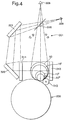
- Fig. 4 shows the camera in a configuration set to view the second region 307 completely via the beam splitter 318. This implies that the camera 308 views either the first region 306 via the splitter, the mirrors 321, 320 and the lens 314, and secondly the second region 307 through the splitter. In this latter situation, the light source 301 is fully or partly activated, and the light source 300 is deactivated.
- the light source 301 suitably comprising a plurality of light sub-sources 302-305, is notably located in a region between the beam splitter 316; 318; 319 and an object supporting means in the form of said compact conveyor and sorter 200.
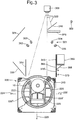
- the object supporting means 200 is shown only schematically, but in more detail on fig. 3 .
- said supporting means is in the form of the rotary drum 220 (see fig. 3 ) with the auxiliary roller 243.
- the drum 220 and the roller 243 will controllably, but forcibly rotate the object 10 on a portion 220' or 220" of the circumference of the drum.
- the drum 220 has at least one radial inwardly directed, adjustable space or cavity 222 for receiving the object 10 after its rotation on said circumference portion and for transporting the object 10 through rotation of the drum to an output location, e.g.
- the camera 308 will be able to view and cause detection of the presence of the object 10 when it has dropped into the adjustable space 222.
- This has a safety function aspect and also a security function aspect., i.e. to prevent any swindle attempt. This means that the drum 220 will not start turning until the camera 308 actually observes and causes detection of the object being present in the space 222 and with the movable element 223 operating as a movable bottom in its fully retracted state.
- the direction which the drum will then turn is determined by set criteria which are compared to recognize characteristic features of the object. Further, in case the contour of the object is to be viewable from above, rather than sideways, it would be advantageous to let at least a part of the rotary drum 220 be provided with a coating which is retro-reflective to light, in particular at the portions labeled 220' and 220" of the drum 220. Such a situation is in particular suitable in connection with the embodiment shown on fig. 6 and will be further explained later.
- the single camera is generally denoted by 308, 308', the reference 308' symbolizing viewing by the camera 308 via e.g. a beam splitter 318 and mirrors 321, 320 (see fig. 4 ).
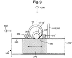
- Said supporting means is suitably in the form of the housing 260 forming a guide with an object receiving input opening 262 and a reciprocating plunger or 270 therein.
- auxiliary roller 273; 273' for roller support upon rotation of the object or item 10; 10'; 10"; 10"' on the plunger 270 when it is set to move with its upper surface 271 past said opening, thus enabling the camera 308 to read an identifying feature on the object or item 10 if not immediately viewable by the camera.
- the plunger 270 is controllable to move beyond said opening 262, e.g. to the position shown by dotted lines 270" to allow the object to drop into the interior of the housing 260 through said opening 262 and by return movement of the plunger 270 (towards left as shown on fig. 9 ) causing the object to be pushed out of the housing to an output location 263.
- the object 10 is camera observable while at a location inside said housing 260 below said opening 262, provided that such location is in at least part of a field of view of the camera 308.
- at least at the upper part 271 of the plunger 270 can be provided with a coating retro-reflective to light, thus enabling the contour of the object, e.g. 10, to be viewed from above.
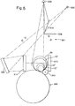
- Fig. 6 shows the use of a single camera 340 and with an optical beam splitter 341 inclined relative to a lens 343.
- a light source 342 provides for illumination of the object, e.g. 10, through lens 343 to provide parallel light rays towards the supporting means 200, which has its drum parts 220' and 220" (see fig. 3 ) provided with retro-reflective material or property enabling light not hit by the object to be retro-reflected back to camera 340 via the lens 343 and the splitter 341 to provide an image of the contour of the object.
- a light source 344 is activated, the light source suitably being of the same type as the light source 301.
- light source 342 may be deactivated, if required.
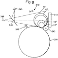
- Fig. 7 shows an embodiment which in operation is similar to that of fig. 6 .
- a single camera 345 is used with an optical beam splitter 346 inclined relative to a lens 347.
- a light source 348 provides for illumination of the object, e.g. 10, through lens 347 to provide parallel light rays towards a light reflective background or area 313 enabling light not hit by the object to be retro-reflected back to camera 345 via the lens 347 and the splitter 346 to provide an image of the contour of the object.
- a light source 349 is activated, the light source suitably being of the same type as the light source 344, i.e.
- Fig. 8 is a modification of the embodiment of fig. 7 , the major difference being the non-existence of the lens 347, thus yielding that the object contour is not viewed by means parallel light rays.
- Figs. 2-5 clearly demonstrate that the first and second regions 306, 307 are partly overlapping, and figs. 6-7 indicate full overlapping.
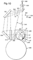
- Fig. 10 is identical to the embodiment shown on fig. 2 , apart from the light source 300 and the retro-reflective background 313 having been deleted and replaced by a light emitting, illuminated or backlit panel 350, the panel 350 thus forming a bright background.
- Ambient light may in some applications be sufficient in order that the camera views a bright background.
- the panel 350 will provide the bright background against which e.g. the object 10 is to be viewed by the single camera 308.
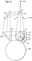
- FIG. 11 A similar situation is present with the embodiment of fig. 11 , which is identical to the embodiment shown on fig. 4 , apart from the light source 300 and the retro-reflective background area 313 having been deleted and replaced by a light emitting area, suitably in the form of the panel 350 to form a bright background against which e.g. the object 10 is to be viewed by the single camera 308 to provide for e.g. detection of object contour.
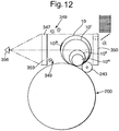
- the further embodiments depicted on fig. 12 and 13 are also related to the use of a light emitting panel 350 to form said bright background and against which camera viewing of an object can be made, as will be further explained.
- Fig. 12 is a modification of the embodiments of fig. 7 .
- the lens 353 which is suitably of same type as lens 347 in fig. 7 or lens 314 in other drawing figures, is present in order to let a single camera 356 view and detect object contour, e.g. contour of object 309 against the panel 350 which in this embodiment constitutes the first light source.
- the second light source is that labeled 349, which could be constituted by two or more light sub-sources.
- the camera 356 uses the lens 347 to enable viewing through use of parallel rays, in order to get as accurate contour image of the object as possible.
- the light source 349 is activated when the camera is to view and read identity features, like e.g. bar code 309', located on the object.
- panel 350 is then not exhibiting a light emitting surface or background area, or its light emitting intensity could suitably be reduced.
- Fig. 13 is an embodiment with a single camera 358 which is capable of viewing an object, e.g. an empty beverage bottle or can 10;10'; 10" or 10"' against a light emitting background area, such as the panel 350 as described earlier.
- an object e.g. an empty beverage bottle or can 10;10'; 10" or 10"' against a light emitting background area, such as the panel 350 as described earlier.
- the light source 359 When the light source 359 is activated, it would be preferable, though not essential, to reduce light intensity from the panel 350 or even turn off emission of light from the panel 350.
- the light source 359 which is similar or identical to the light source 349, could be constituted by two or more sub-sources.
- the first and second light sources e.g. 300, 301; 300', 301; 342, 344; 348, 349; 350, 301; 350, 354; 350, 349; 350, 359 have different spectral range or composition.
- the second light sources 301; 344; 349; 359 composed of two or more sub-sources.
- the sub-sources could have different spectra range or composition, either all different, different in pairs or in groups.
- Such features of the light sources and possible sub-sources are of importance to be able to detect e.g. identifying features on the objects appearing e.g. with different colours, different reflective properties etc.
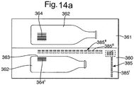
- fig. 14 In the particular case of the embodiments of figs. 2 , 3 and 5 , as well as fig. 10 , it would be suitable to split the camera video image in two with a part 360 related to the first region 306 and another part 361 related to the second region 307.
- figs. 4 and 11 it may be visualized the possibility of dedicating half of the camera video image to region 306 and the other half to region 307, or alternatively have alternating full video images of regions 306 and 307.
- the choice is alternating full video images only.
- Camera viewing of the first region of the object 362 related to its contour 363 can in addition, include observation or rather recognition of mere presence or absence of said identifying features 364, e.g. bar code located on the object.
- the focus of the camera will not be exactly on the features 364, but the camera will at least sense or detect with relation to the partial image 360 whether the features 364, here labeled 364' are indeed present or not, although on the partial image 360 appearing "blurred” or a bit out of focus. If the features 364 are not visible on the image part 361, but visible on part 360, this will indicate necessity to rotate the object one way or the other through a maximum angle of 180°.
- the comparison between the two images 360 and 361 in this respect has some impact on the required amount of rotation of the object in order to be able to view and read the feature 364 properly in region 307, and consequently has also importance with regard to processing time in order to find the feature 364, read and record it.
- the camera has preferably, but not necessarily its image field subdivided into said at least two partial images 360, 361, the first partial image 360 being dedicated to object contour detection and/ or detection of presence or absence of said identifying features, and the second partial image 361 being dedicated to observation and reading of said identifying features.
- the invention is in this aspect focused on implementation of safety measures which are provided from actions obtained by operating a hardware circuit which is adapted to read predefined or dedicated pixels on the sensor matrix of the camera, i.e. reading hardware assigned physical pixels of the camera sensor matrix when a camera image is made.
- This aspect of the invention is therefore through use of camera functionality able to provide an efficient hardware implemented light curtain functionality, as will be more closely explained in the following description with reference to figs. 14a , 14b , 14c , 15a , 15b and 16 .
- a camera image such as e.g. image 360 or 385 for detection of so-called "border crossing", i.e. an event in a field of view of the camera.
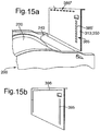
- the bright or light emitting background 313 350 located at least one array or column 385 of repeatedly occurring dark markings 385', e.g. black squares at an in-feed region receiving objects in direction 388 at which objects are fed into the apparatus for viewing, detection, turning and sorting, as previously disclosed. Further, there may on the background 313; 350 be located at least one array or row 385" of repeatedly occurring dark markings 385"'. At least one such row may be useful if the entry or in-feed region causes objects to be fed in a direction 388'.
- the array 385" is present to assist in providing additional light curtain functionality.
- markings 385', 385"' indicated on fig. 15a there could be located markings 395, 396 and 397 in the form of solid lines, as indicated on fig. 15b .
- Fig. 14a exhibits two half-images 360 and 361, as previous discussed, whereas fig .14b exhibits a generalized full image 386 as provided by the available pixels on a camera image sensor matrix 401' (see fig. 14c ).
- the dotted line 387 and/ or 387' on fig. 14b denotes, relative to the camera image, a fraction or fractions of matrix pixels being a selected part of the available sensor matrix pixels.
- Said fraction 387 of sensor matrix pixels is dedicated to detection of the array or column of markings, as well as any events observable by said fraction of pixels and which could trigger an action, such as stopping operation of a motor, e.g.
- said fraction 387' of sensor matrix pixels is dedicated to detection of the array 385" or row of markings, as well as any events observable by said fraction of pixels and which could trigger an action, such as stopping operation of a motor, e.g. motor 404 or 422 with reference to figs. 16 and 17 .
- the arrays 385 and 385" of markings 385' and 385"' could both be present, yielding that both fractions 387 and 387' will be active for detection of markings and observable events.
- a background area 314; 350 is located in the camera field of view, and as shown on e.g. fig. 15a , said background area in a part thereof exhibits the array 385 of distinguished markings 385'.
- the background area 313; 350 is located in a camera viewing chamber of a reverse vending machine.
- the chamber or input receiving area 210 has entry opening (see 425 on fig. 16 ) into which an object 10 in the form of an empty beverage container to be viewed by the camera, is insertable.
- the array 387 of markings is located at an entry opening or region 425 of said viewing chamber 210.
- the in-feed direction for objects is indicated by reference numeral 388 on fig. 14b .
- the array of markings is in a predefined pattern, suitably a column 385 of mutually spaced markings 385'.
- a predefined pattern suitably a column 385 of mutually spaced markings 385'.
- an additional predefined pattern 385" of mutually spaced markings 385'" extending as e.g. an upper row, to provide an addition light curtain and to safeguard against any safety hazards caused by someone trying to put e.g. a hand into the viewing chamber from above, as e.g. indicated by reference numeral 388'.
- the fraction 387 and/ or fraction 387' of sensor matrix pixels 401' in the camera 400 will be dedicated to providing an image of said markings 385' and / or 385"' against said background area.
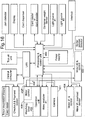
- the fraction 387 and/ or fraction 387' of pixels will be readable by an operating unit 408, the response of which is dictated by its hardware functions and inputs to the unit 408.
- the operating unit 408 is operatively linked with the camera 401 to read said fraction of sensor matrix pixels. Further, the operating unit 408 is linked to a digital processing and control unit 400, said unit 400 controlling operation of the camera, i.e. when a camera image is to be taken.
- the operating unit has a set of stored reference pixel signal values which are respectively related to pixels in said fraction of sensor matrix pixels, and which are related to said background area 313; 350 and said array 387 of distinguished markings thereon.
- the operating unit 408 is capable of comparing a read pixel signal value from a respective pixel in said fraction of pixels with corresponding reference signal value assigned to such respective pixel, and to output respective comparison signal, however said operating unit 408 having an output 408'; 408" capable of changing signal state of delivered signal 393, suitably into a disabling or deactivating signal when said comparison signal or for that matter a set of such comparison signals departs from a predefined condition.
- the operating unit 408 will, when the comparison satisfies the predefined condition, provide a signal 393 which enables the equipment to remain in operation.
- Such equipment could e.g. be found in a reverse vending machine as disclosed in the description and shown on the drawings.
- the operating unit 408 is made to execute hardware functions, and the operating unit can be of a logic network of a type well known to any skilled person in the art and connected to execute the required functions.
- the operating unit can be made from a plurality of discrete functional building blocks or a single integrated circuit (IC) as an application specified integrated circuit (ASIC), e.g. as a so-called Gate Array, or as an implementation in a programmable circuit, so-called Field Programmable Gate Array (FPGA).
- ASIC application specified integrated circuit
- FPGA Field Programmable Gate Array
- the operating unit 408 may include a watchdog timer 403 which is designed to check that reading of pixel signals from said fraction of pixels and comparison with reference pixel signal values are made at a minimum rate of iteration. The reading of pixels is initiated from the processing and control unit 400. If said minimum rate of iteration is below a set value, the operating unit 408 may output said signal 393 in a state thereof causing disablement or shut-down of operation of equipment controlled by the unit 408.
- the signal 393 in a deactivating state will normally be present until such a point of time when a new surveillance image taken meets all preset criteria for not issuing such deactivation type of signal.
- a synchronization of the camera and a light source providing a bright or illuminated background area Preferably there is used a light reflective material 313 at the camera field of view onto which said dark squares 385' have been applied.
- a light reflective material 313 at the camera field of view onto which said dark squares 385' have been applied Preferably there is used a light reflective material 313 at the camera field of view onto which said dark squares 385' have been applied.
- the background 350 is a back-lit or illuminated panel, it could be visualized synchronized operation thereof with the operation of the camera.
- surveillance images of the chamber or area 210 will have to be generated frequently.
- the camera 401 it will by means of the operating unit 408 and with aid of the unit 400 be checked first if a complete bright line exists, i.e. all matrix pixel values above a predefined dark level threshold. If this is the case, there will be a search for alternating dark and bright areas along a predefined column, such as column 385.
- the detected image of dark areas 385' should be within minimum and maximum length requirements to pass acceptance.
- the bright areas must be of a minimum length before accepted. Also, the image must end with an accepted bright area.
- an accumulated number of accepted dark areas must equal a predefined number.
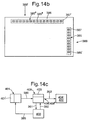
- Fig. 14c is a system block diagram specifically related to the light curtain functionality, and should be considered essentially as part of the block schematic shown on fig. 16 .
- the camera 401 is controlled by a digital processor 400 associated with the operating unit.
- This processor is in fig. 16 denoted as a processing and control unit 400.
- Line 389 denotes camera control, and the camera delivers image data signals on line 390 to the operating device 408.
- the operating device 408 has a watchdog timer 403 connected thereto.
- the unit 400 suitably controls triggering of camera imaging, as well as synchronization of the camera and any background illumination.
- Image data are conveyed from the operating unit 408 to the processor 400 via line 392, and the processor 400 provides the operating unit 408 with certain control signals via line 392.
- the processor 400 is suitably the main processor of the overall system, although this is not necessarily so.
- the dedicated set of sensor matrix pixels forming a fractional part of the total number of sensor matrix pixels is not selected through use of software, but is instead related to a limited number of physical pixels or elements on the camera image sensor matrix.
- the light curtain function is important from an operational safety point of view, it is therefore absolutely essential that the light curtain function is not at all software based.
Landscapes
- General Physics & Mathematics (AREA)
- Physics & Mathematics (AREA)
- Health & Medical Sciences (AREA)
- Life Sciences & Earth Sciences (AREA)
- Chemical & Material Sciences (AREA)
- Analytical Chemistry (AREA)
- Biochemistry (AREA)
- General Health & Medical Sciences (AREA)
- Immunology (AREA)
- Pathology (AREA)
- Control Of Vending Devices And Auxiliary Devices For Vending Devices (AREA)
- Sorting Of Articles (AREA)
- Refuse Collection And Transfer (AREA)
- Warehouses Or Storage Devices (AREA)
- Vending Machines For Individual Products (AREA)
- Discharge Of Articles From Conveyors (AREA)
- Telephone Function (AREA)
- Specific Conveyance Elements (AREA)
- Looms (AREA)
- Spinning Or Twisting Of Yarns (AREA)
- Telephonic Communication Services (AREA)
- Length Measuring Devices By Optical Means (AREA)
Claims (8)
- Sicherheitsvorrichtung zum Steuern des Betriebes von Funktionsausrüstung (200; 243; 404; 422) mit beweglichen Teilen, wobei die Vorrichtung dafür konfiguriert ist, eine Kamera zu verwenden, um ein sicherheitsrelevantes Ereignis in einem Sichtfeld der Kamera zu betrachten und dessen Erkennung zu bewirken, dadurch gekennzeichnet:- dass ein Hintergrundbereich (313; 350) in dem Sichtfeld der Kamera liegt, wobei der Hintergrundbereich in einem Teil von sich einen Satz stationärer Markierungen (385; 385'; 385"; 385"') aufweist,- dass ein Anteil von Sensormatrixpixeln in der Kamera dafür reserviert ist, ein Bild der Markierungen bereitzustellen, wobei der Anteil von Pixeln mit einer hardware-konfigurierten Betriebseinheit (408) lesbar ist,- dass die Betriebseinheit (408) einen Satz gespeicherter Referenzpixel-Signalwerte aufweist, die sich jeweils zu Pixeln in dem Anteil von Sensormatrixpixeln beziehen und die sich auf den Hintergrundbereich und die Anordnung von unterschiedenen Markierungen darauf beziehen,- dass die Betriebseinheit (408) dafür hardware-konfiguriert ist, einen gelesenen Pixelsignalwert von einem entsprechenden Pixel in dem Anteil von Pixeln mit einem entsprechenden Referenzsignalwert zu vergleichen, der einem derartigen entsprechenden Pixel zugewiesen ist, und ein entsprechendes Vergleichssignal auszugeben, und- die Betriebseinheit (408) eine Ausgabe aufweist, die in der Lage ist, ihren Signalzustand des gelieferten Signals zu verändern, wenn das Vergleichssignal oder ein Satz derartiger Vergleichssignale von einer vordefinierten Bedingung abweicht, wobei das gelieferte Signal ein Abschalt- oder Deaktivierungssignal und dafür wirksam ist, das Abschalten oder einen unterbrochenen Betrieb der Funktionsausrüstung (200; 243; 404; 422) zu bewirken, wenn das Vergleichssignal oder der Satz derartiger Vergleichssignale von der vordefinierten Bedingung abweicht.
- Vorrichtung nach Anspruch 1, wobei sich die Funktionsausrüstung (200; 243; 404; 422) in einem Leergutautomaten (1) zur Aufnahme leerer Getränkebehälter (10; 10'; 10"; 10"') befindet.
- Vorrichtung nach Anspruch 1 oder 2, wobei sich der Hintergrundbereich in einer Kamerabetrachtungskammer eines Leergutautomaten befindet, wobei die Kammer mindestens eine Eingangsöffnung aufweist, in die ein Gegenstand in Form eines leeren Getränkebehälters einführbar ist, um durch die Kamera betrachtet zu werden, und wobei sich der Satz von Markierungen an einer Eingangsregion der Betrachtungskammer und/oder an einer oder mehreren Randregionen des Hintergrundbereiches befindet.
- Vorrichtung nach Anspruch 1 oder 3, wobei der Satz von Markierungen mindestens eines des Folgenden umfasst:ein Muster aus mindestens einer Spalte gegenseitig beabstandeter Markierungen,ein Muster aus mindestens einer Reihe gegenseitig beabstandeter Markierungen,mindestens eine liegende, z. B. horizontale, markierte Linie,ein Muster aus gegenseitig beabstandeten Markierungen, die in mindestens einer Spalte und in mindestens einer Reihe angeordnet sind, undein Muster aus gegenseitig beabstandeten Markierungen, die in mindestens einer Spalte und in mindestens einer liegenden, z. B. horizontalen, markierten Linie angeordnet sind.
- Vorrichtung nach Anspruch 3 oder 4, wobei die Kammer eine Eingangsöffnung und eine Ausgangsöffnung aufweist, die aneinander ausgerichtet sind, und wobei sich der Satz von Markierungen an oder neben den Öffnungen befindet.
- Vorrichtung einem der Ansprüche 1 - 5, wobei die Betriebseinheit (408) eine Laufzeitüberwachung (403) beinhaltet, um zu überprüfen, dass das Lesen von Pixelsignalen von dem Anteil von Pixeln und das Vergleichen mit Referenzpixel-Signalwerten mit einer Mindestwiederholungsrate erfolgt.
- Vorrichtung nach Anspruch 6, wobei die Betriebseinheit (408) dafür konfiguriert ist, an ihrem Ausgang ihren Signalstatus in ein Abschalt- oder Deaktivierungssignal zu ändern, wenn die Mindestwiederholungsrate unter einem eingestellten Wert liegt, um den Betrieb der Funktionsausrüstung mit beweglichen Teilen abzuschalten oder zu unterbrechen.
- Vorrichtung einem der Ansprüche 1 - 7, wobei die Betriebseinheit (408) aus einem der Folgendem besteht:- mehreren einzelnen Funktionsbausteinen,- einer anwendungsspezifischen integrierten Schaltung (ASIC), z. B. einem sogenannten Gate-Array, und- einer Umsetzung in einer programmierbaren Schaltung der Art eines feldprogrammierbaren Gate-Arrays (FPGA).
Applications Claiming Priority (9)
| Application Number | Priority Date | Filing Date | Title |
|---|---|---|---|
| NO20050406 | 2005-01-25 | ||
| NO20050402A NO20050402D0 (no) | 2005-01-25 | 2005-01-25 | Deteksjonsanordning |
| NO20050404 | 2005-01-25 | ||
| NO20050405 | 2005-01-25 | ||
| NO20050403 | 2005-01-25 | ||
| NO20050407 | 2005-01-25 | ||
| NO20050401A NO20050401D0 (no) | 2005-01-25 | 2005-01-25 | Kamera-assistert anordning for a betrakte et objekt |
| EP06701103.1A EP1842169B1 (de) | 2005-01-25 | 2006-01-24 | Mittel in einem rücknahmeautomaten für die entgegennahme, behandlung, sortierung von mehrwegobjekten |
| PCT/NO2006/000029 WO2006080851A2 (en) | 2005-01-25 | 2006-01-24 | Means in a reverse vending machine (rvm) for receiving, handling, sorting and storing returnable items or objects |
Related Parent Applications (2)
| Application Number | Title | Priority Date | Filing Date |
|---|---|---|---|
| EP06701103.1A Division EP1842169B1 (de) | 2005-01-25 | 2006-01-24 | Mittel in einem rücknahmeautomaten für die entgegennahme, behandlung, sortierung von mehrwegobjekten |
| EP06701103.1A Division-Into EP1842169B1 (de) | 2005-01-25 | 2006-01-24 | Mittel in einem rücknahmeautomaten für die entgegennahme, behandlung, sortierung von mehrwegobjekten |
Publications (2)
| Publication Number | Publication Date |
|---|---|
| EP1947616A1 EP1947616A1 (de) | 2008-07-23 |
| EP1947616B1 true EP1947616B1 (de) | 2019-07-31 |
Family
ID=36609269
Family Applications (8)
| Application Number | Title | Priority Date | Filing Date |
|---|---|---|---|
| EP08152913.3A Expired - Lifetime EP1947614B1 (de) | 2005-01-25 | 2006-01-24 | Förderbandmittel für zurücksendbare Elemente |
| EP08152917.4A Expired - Lifetime EP1947616B1 (de) | 2005-01-25 | 2006-01-24 | Sicherheitsvorrichtung zum Steuern des Betriebs der Funktionsausrüstung mit beweglichen Teilen |
| EP08152912.5A Expired - Lifetime EP1947613B1 (de) | 2005-01-25 | 2006-01-24 | Drehförderband für Pfandgegenstände |
| EP20080152921 Withdrawn EP1947618A1 (de) | 2005-01-25 | 2006-01-24 | Treibervorrichtung in einem Rücknahmeautomat |
| EP19151910.7A Expired - Lifetime EP3499471B1 (de) | 2005-01-25 | 2006-01-24 | Mittel in rücknahmeautomaten zum aufnehmen, handhaben, sortieren und aufbewahren von rückgabeartikeln oder -objekten |
| EP06701103.1A Expired - Lifetime EP1842169B1 (de) | 2005-01-25 | 2006-01-24 | Mittel in einem rücknahmeautomaten für die entgegennahme, behandlung, sortierung von mehrwegobjekten |
| EP08152919.0A Expired - Lifetime EP1947617B1 (de) | 2005-01-25 | 2006-01-24 | Markensystem zur Installation in einem umgekehrten Verkaufsautomaten |
| EP08152915.8A Expired - Lifetime EP1947615B1 (de) | 2005-01-25 | 2006-01-24 | Vorrichtung für eine Kameraansicht eines Objekts |
Family Applications Before (1)
| Application Number | Title | Priority Date | Filing Date |
|---|---|---|---|
| EP08152913.3A Expired - Lifetime EP1947614B1 (de) | 2005-01-25 | 2006-01-24 | Förderbandmittel für zurücksendbare Elemente |
Family Applications After (6)
| Application Number | Title | Priority Date | Filing Date |
|---|---|---|---|
| EP08152912.5A Expired - Lifetime EP1947613B1 (de) | 2005-01-25 | 2006-01-24 | Drehförderband für Pfandgegenstände |
| EP20080152921 Withdrawn EP1947618A1 (de) | 2005-01-25 | 2006-01-24 | Treibervorrichtung in einem Rücknahmeautomat |
| EP19151910.7A Expired - Lifetime EP3499471B1 (de) | 2005-01-25 | 2006-01-24 | Mittel in rücknahmeautomaten zum aufnehmen, handhaben, sortieren und aufbewahren von rückgabeartikeln oder -objekten |
| EP06701103.1A Expired - Lifetime EP1842169B1 (de) | 2005-01-25 | 2006-01-24 | Mittel in einem rücknahmeautomaten für die entgegennahme, behandlung, sortierung von mehrwegobjekten |
| EP08152919.0A Expired - Lifetime EP1947617B1 (de) | 2005-01-25 | 2006-01-24 | Markensystem zur Installation in einem umgekehrten Verkaufsautomaten |
| EP08152915.8A Expired - Lifetime EP1947615B1 (de) | 2005-01-25 | 2006-01-24 | Vorrichtung für eine Kameraansicht eines Objekts |
Country Status (16)
| Country | Link |
|---|---|
| US (5) | US7997417B2 (de) |
| EP (8) | EP1947614B1 (de) |
| JP (6) | JP5015011B2 (de) |
| CY (1) | CY1121574T1 (de) |
| DK (4) | DK1842169T3 (de) |
| ES (7) | ES3025744T3 (de) |
| FI (1) | FI3499471T3 (de) |
| HR (1) | HRP20190701T1 (de) |
| HU (2) | HUE044105T2 (de) |
| LT (1) | LT1842169T (de) |
| NO (7) | NO343497B1 (de) |
| PL (2) | PL1947614T3 (de) |
| PT (1) | PT1842169T (de) |
| RS (1) | RS58668B1 (de) |
| SI (1) | SI1842169T1 (de) |
| WO (1) | WO2006080851A2 (de) |
Families Citing this family (102)
| Publication number | Priority date | Publication date | Assignee | Title |
|---|---|---|---|---|
| EP1947614B1 (de) * | 2005-01-25 | 2018-10-10 | Tomra Systems ASA | Förderbandmittel für zurücksendbare Elemente |
| US20070174071A1 (en) | 2006-01-20 | 2007-07-26 | C&C Acquisition, Llc | Techniques for managing information relating to recyclable containers |
| US20070276686A1 (en) * | 2006-01-20 | 2007-11-29 | Count & Crush, Llc | Techniques for processing recyclable containers |
| EP1975891A1 (de) * | 2007-03-28 | 2008-10-01 | Wincor Nixdorf International GmbH | Vorrichtung und Verfahren zur Rücknahme von Gebinden |
| GB2449213B (en) | 2007-05-18 | 2011-06-29 | Kraft Foods R & D Inc | Improvements in or relating to beverage preparation machines and beverage cartridges |
| EP2232197A4 (de) * | 2007-11-07 | 2014-04-02 | Tomra Systems Asa | Vorrichtung, optische einheit und einrichtungen zur verwendung bei der detektion von objekten |
| DE102008006382A1 (de) | 2008-01-29 | 2009-07-30 | Wincor Nixdorf International Gmbh | Erkennung von Material und Füllzustand von Leergutbehältern |
| US11264124B2 (en) | 2008-02-20 | 2022-03-01 | Chudy Group, LLC | System and apparatus for item management |
| US8380346B2 (en) | 2008-02-20 | 2013-02-19 | Chundy Group, LLC | System and apparatus for item management |
| US8200533B2 (en) * | 2008-10-02 | 2012-06-12 | ecoATM, Inc. | Apparatus and method for recycling mobile phones |
| US11010841B2 (en) | 2008-10-02 | 2021-05-18 | Ecoatm, Llc | Kiosk for recycling electronic devices |
| US7881965B2 (en) | 2008-10-02 | 2011-02-01 | ecoATM, Inc. | Secondary market and vending system for devices |
| US10853873B2 (en) | 2008-10-02 | 2020-12-01 | Ecoatm, Llc | Kiosks for evaluating and purchasing used electronic devices and related technology |
| US9881284B2 (en) | 2008-10-02 | 2018-01-30 | ecoATM, Inc. | Mini-kiosk for recycling electronic devices |
| CN105303699B (zh) | 2008-10-02 | 2018-10-09 | 埃科亚特姆公司 | 针对设备的二手市场和自动售货系统 |
| JP5359635B2 (ja) * | 2008-12-11 | 2013-12-04 | 富士電機株式会社 | 賞味期限読取装置 |
| DE102009026160A1 (de) | 2009-07-13 | 2011-01-27 | Wincor Nixdorf International Gmbh | Vorrichtung und Verfahren zum Erkennen von charakteristischen Merkmalen eines Leergutbehälters |
| WO2011066839A1 (en) * | 2009-12-04 | 2011-06-09 | Anker Andersen A/S | Reverse vending system for batch registration of used beverage containers |
| US9098959B2 (en) * | 2010-01-12 | 2015-08-04 | Robert Baric | Multi-sided vending machine |
| US9105144B2 (en) | 2010-01-12 | 2015-08-11 | Robert J. Baric | Multiple-sided vending machine |
| WO2011089013A1 (de) * | 2010-01-25 | 2011-07-28 | Wincor Nixdorf International Gmbh | Vorrichtung und verfahren zum erkennen von charakteristischen merkmalen eines leergutbehälters |
| US20110245965A1 (en) * | 2010-03-31 | 2011-10-06 | Farrell Patrick A | Method and Apparatus for Procurement and Resale of New and Used Media |
| US8538581B2 (en) * | 2010-09-03 | 2013-09-17 | Redbox Automated Retail, Llc | Article vending machine and method for authenticating received articles |
| DE102010037448A1 (de) * | 2010-09-10 | 2012-03-15 | Wincor Nixdorf International Gmbh | Verfahren und Vorrichtung zur Erfassung von Leergutbehältern |
| US9792104B2 (en) | 2010-11-05 | 2017-10-17 | FedEx Supply Chain Logistics & Electronics, Inc. | System and method for flashing a wireless device |
| US9575973B2 (en) | 2010-11-05 | 2017-02-21 | Atc Logistics & Electronics, Inc. | System and method for systematically removing customer personal information from an electronic device |
| US9311488B2 (en) | 2010-11-05 | 2016-04-12 | Atc Logistics & Electronics, Inc. | System and method for removing customer personal information from an electronic device |
| US9495367B2 (en) * | 2010-11-05 | 2016-11-15 | Atc Logistics & Electronics, Inc. | System and method for performing a software comparison |
| EP2655084B1 (de) * | 2010-12-21 | 2015-02-18 | Akzo Nobel Coatings International B.V. | Farbchipausgabe |
| CN103459991A (zh) | 2011-01-31 | 2013-12-18 | 维泰克实验室技术股份有限公司 | 具有数字的体积显示的瓶式分配器 |
| CA3210819A1 (en) | 2011-04-06 | 2012-10-11 | Ecoatm, Llc | Method and kiosk for recycling electronic devices |
| MX344332B (es) | 2011-05-04 | 2016-12-13 | Kiosk Information Systems Inc | Sistemas y metodos para la exhibicion de mercancia, la venta y el control de inventario. |
| EP4053811A1 (de) * | 2011-06-24 | 2022-09-07 | Tomra Systems ASA | Verfahren und vorrichtung zur erkennung von betrugsversuchen in leergutrücknahmeautomaten |
| US20130081548A1 (en) * | 2011-08-26 | 2013-04-04 | Wastequip, Llc | Waste compactor |
| DE102011053179A1 (de) * | 2011-09-01 | 2013-03-07 | Wincor Nixdorf International Gmbh | Vorrichtung zur Rücknahme von Leergut und Verfahren zum Klassifizieren von Leergut mit Hilfe von Lichtfeldern |
| KR20130075527A (ko) * | 2011-12-27 | 2013-07-05 | 삼성전자주식회사 | 다이 어태치 장치 |
| US20130221018A1 (en) * | 2012-02-27 | 2013-08-29 | Brent D. Garson | Vending machine method and apparatus |
| US20140002642A1 (en) | 2012-06-15 | 2014-01-02 | Elmar SWIEGOT | Absolute position detection |
| US20140207600A1 (en) * | 2012-08-24 | 2014-07-24 | Daniel Ezell | System and method for collection and management of items |
| US9317989B2 (en) | 2012-10-02 | 2016-04-19 | Kiosk Information Systems, Inc. | Camera audit accepter mechanism and camera audit dispensing mechanism |
| US10210693B2 (en) | 2012-10-29 | 2019-02-19 | Waèl M. Hannawa | Reverse vending machine incorporating a method of cleaning therein |
| US9890914B2 (en) | 2013-01-18 | 2018-02-13 | Raves Equipment Company | Lighting assembly |
| US9002742B2 (en) | 2013-03-14 | 2015-04-07 | Elisah DUMAS | Computer implemented method for a recycling company to increase recycling demand |
| TW201333861A (zh) * | 2013-04-15 | 2013-08-16 | Kai-Yi Yang | 自動交易站與其結合銷售網站之交易方法 |
| US9329142B2 (en) * | 2013-12-10 | 2016-05-03 | Key Technology, Inc. | Object imaging assembly |
| CN103778712A (zh) * | 2013-12-27 | 2014-05-07 | 施永红 | 一种声控饮品交换机的装置 |
| DE102014100699A1 (de) * | 2014-01-22 | 2015-07-23 | Krones Ag | Vorrichtung zur optischen Inspektion von Verpackungsgegenständen in der Getränketechnologie |
| DK2905086T3 (en) * | 2014-01-30 | 2017-03-06 | Wincor Nixdorf Int Gmbh | Process for sorting containers |
| EP2905756B1 (de) | 2014-02-06 | 2017-06-21 | Wincor Nixdorf International GmbH | Paketverarbeitungseinrichtung |
| US9292991B2 (en) * | 2014-02-28 | 2016-03-22 | TOMRA North America, Inc. | Receptacle assembly and a reverse vending machine comprising said receptacle assembly |
| US9275293B2 (en) | 2014-02-28 | 2016-03-01 | Thrift Recycling Management, Inc. | Automated object identification and processing based on digital imaging and physical attributes |
| US10401411B2 (en) | 2014-09-29 | 2019-09-03 | Ecoatm, Llc | Maintaining sets of cable components used for wired analysis, charging, or other interaction with portable electronic devices |
| EP3859697A1 (de) | 2014-10-02 | 2021-08-04 | ecoATM, LLC | Anwendung zur vorrichtungsevaluierung und für andere prozesse im zusammenhang mit dem recycling von vorrichtungen |
| WO2016053378A1 (en) | 2014-10-02 | 2016-04-07 | ecoATM, Inc. | Wireless-enabled kiosk for recycling consumer devices |
| US10445708B2 (en) | 2014-10-03 | 2019-10-15 | Ecoatm, Llc | System for electrically testing mobile devices at a consumer-operated kiosk, and associated devices and methods |
| US20170169401A1 (en) | 2015-12-11 | 2017-06-15 | ecoATM, Inc. | Systems and methods for recycling consumer electronic devices |
| WO2016069738A1 (en) | 2014-10-31 | 2016-05-06 | ecoATM, Inc. | Systems and methods for recycling consumer electronic devices |
| WO2016069742A1 (en) | 2014-10-31 | 2016-05-06 | ecoATM, Inc. | Methods and systems for facilitating processes associated with insurance services and/or other services for electronic devices |
| EP4560549A3 (de) | 2014-11-06 | 2025-06-18 | ecoATM, LLC | Verfahren und systeme zur beurteilung und wiederverwendung elektronischer vorrichtungen |
| WO2016094789A1 (en) | 2014-12-12 | 2016-06-16 | ecoATM, Inc. | Systems and methods for recycling consumer electronic devices |
| EP3035303B1 (de) * | 2014-12-17 | 2020-03-25 | Wincor Nixdorf International GmbH | Rücknahmeautomat |
| US9969514B2 (en) * | 2015-06-11 | 2018-05-15 | Empire Technology Development Llc | Orientation-based hashing for fast item orientation sensing |
| US10427819B2 (en) | 2015-08-25 | 2019-10-01 | Chudy Group, LLC | Plural-mode automatic medicament packaging system |
| EP4137385B1 (de) | 2015-09-02 | 2025-10-29 | Volvo Truck Corporation | Vorrichtung und verfahren zum rückwärtsfahren einer gelenkfahrzeugkombination |
| KR101598763B1 (ko) * | 2015-10-26 | 2016-02-29 | 고민규 | 꽃다발 자동 판매기 |
| CN105243739B (zh) * | 2015-11-05 | 2017-10-17 | 上海华铭智能终端设备股份有限公司 | 卡箱回收设备异常行为监测装置 |
| EP3208781B1 (de) * | 2016-02-22 | 2020-08-26 | Wincor Nixdorf International GmbH | Leergut-rücknahme-vorrichtung |
| EP3208782B1 (de) | 2016-02-22 | 2022-10-19 | Wincor Nixdorf International GmbH | Leergutrücknahmevorrichtung |
| IL244872B (en) | 2016-04-03 | 2022-03-01 | Treitel Chemical Eng Ltd | Apparatus and method for dosing powdery or granular material |
| US12560467B2 (en) | 2016-04-03 | 2026-02-24 | Treitel Chemical Engineering Ltd. | Apparatus and method for dosaging powdered or granulated material |
| US10127647B2 (en) | 2016-04-15 | 2018-11-13 | Ecoatm, Llc | Methods and systems for detecting cracks in electronic devices |
| CN105788075A (zh) * | 2016-04-20 | 2016-07-20 | 谭小军 | 易拉罐分类装置、系统及自动售货装置 |
| US9885672B2 (en) | 2016-06-08 | 2018-02-06 | ecoATM, Inc. | Methods and systems for detecting screen covers on electronic devices |
| US10269110B2 (en) | 2016-06-28 | 2019-04-23 | Ecoatm, Llc | Methods and systems for detecting cracks in illuminated electronic device screens |
| CN106000908A (zh) * | 2016-07-05 | 2016-10-12 | 广州慧翼智能科技有限公司 | 一种用于药瓶高速读码装置 |
| AU2017293129B2 (en) * | 2016-07-06 | 2023-03-09 | Tomra Systems Asa | Device and method for singulation of used beverage or food containers |
| KR101743400B1 (ko) * | 2016-08-24 | 2017-06-15 | 이도섭 | 빈병집하장치 및 방법 |
| USD874570S1 (en) * | 2017-09-01 | 2020-02-04 | Tomra Systems Asa | Reverse vending machine |
| US10358247B2 (en) | 2017-10-27 | 2019-07-23 | Chudy Group, LLC | Compartmentalized container loading and management system |
| CN109377646A (zh) * | 2017-11-30 | 2019-02-22 | 金超 | 一种无人售货便利店整体运营模式 |
| JP7410958B2 (ja) * | 2018-10-31 | 2024-01-10 | トムラ、システムズ、アーエスアー | 容器回収機装置および関連する方法 |
| US12322259B2 (en) | 2018-12-19 | 2025-06-03 | Ecoatm, Llc | Systems and methods for vending and/or purchasing mobile phones and other electronic devices |
| KR102942007B1 (ko) | 2018-12-19 | 2026-03-19 | 에코에이티엠, 엘엘씨 | 이동 전화기 및 다른 전자 디바이스의 판매 및/또는 구매를 위한 시스템 및 방법 |
| EP3924918B1 (de) | 2019-02-12 | 2026-04-01 | ecoATM, LLC | Kiosk zur bewertung und zum einkaufen von gebrauchten elektronischen geräten |
| US11462868B2 (en) | 2019-02-12 | 2022-10-04 | Ecoatm, Llc | Connector carrier for electronic device kiosk |
| US11798250B2 (en) | 2019-02-18 | 2023-10-24 | Ecoatm, Llc | Neural network based physical condition evaluation of electronic devices, and associated systems and methods |
| CN110902210B (zh) * | 2019-12-16 | 2022-04-08 | 何雨庭 | 一种小型家用垃圾自动分类机 |
| JP2023508903A (ja) | 2019-12-18 | 2023-03-06 | エコエーティーエム, エルエルシー | 携帯電話および他の電子デバイスを販売および/または買取するためのシステムならびに方法 |
| WO2021176441A1 (en) * | 2020-03-01 | 2021-09-10 | Polytex Technologies Ltd. | Smart textile items dispensing and return systems |
| US20230326277A1 (en) * | 2020-06-22 | 2023-10-12 | DataShield Corporation | System and method for tracking document shredding and voter ballots |
| WO2022040667A1 (en) | 2020-08-17 | 2022-02-24 | Ecoatm, Llc | Evaluating an electronic device using a wireless charger |
| US11922467B2 (en) | 2020-08-17 | 2024-03-05 | ecoATM, Inc. | Evaluating an electronic device using optical character recognition |
| EP4197083B1 (de) | 2020-08-17 | 2024-10-09 | ecoATM, LLC | Verbinderträger für kiosk einer elektronischen vorrichtung |
| US12271929B2 (en) | 2020-08-17 | 2025-04-08 | Ecoatm Llc | Evaluating an electronic device using a wireless charger |
| EP4738801A2 (de) | 2020-08-25 | 2026-05-06 | ecoATM, LLC | Evaluation und wiederverwendung elektronischer vorrichtungen |
| WO2022112828A1 (en) * | 2020-11-25 | 2022-06-02 | Eskandari Mohammad Bagher | The technology of detecting the type of recyclable materials with sound processing |
| CN112741520B (zh) * | 2021-01-19 | 2022-02-18 | 昭星实业(深圳)有限公司 | 一种具有人脸识别功能的智能消毒液洗手机 |
| NL2028650B1 (en) | 2021-05-28 | 2022-12-12 | Mr Fill Holding B V | Device, system and method for receiving and handling beverage containers |
| IT202100015302A1 (it) * | 2021-06-11 | 2022-12-11 | Microhard Srl | Magazzino automatico per lo stoccaggio e l'erogazione di prodotti |
| US12462635B2 (en) | 2021-07-09 | 2025-11-04 | Ecoatm, Llc | Identifying electronic devices using temporally changing information |
| WO2024165696A1 (en) | 2023-02-08 | 2024-08-15 | Tomra Systems Asa | A container return system and method |
| WO2024249111A1 (en) * | 2023-06-02 | 2024-12-05 | DataShield Corporation | System and method for tracking document shredding and voter ballots |
Citations (2)
| Publication number | Priority date | Publication date | Assignee | Title |
|---|---|---|---|---|
| WO1983001855A1 (en) * | 1981-11-19 | 1983-05-26 | Minnesota Mining & Mfg | Optically based intrusion detector |
| EP1262905A2 (de) * | 2001-05-30 | 2002-12-04 | Leuze electronic GmbH | Optoelektronische Vorrichtung |
Family Cites Families (45)
| Publication number | Priority date | Publication date | Assignee | Title |
|---|---|---|---|---|
| US2003114A (en) * | 1934-11-26 | 1935-05-28 | Samuel J Goldsmith | Garment protector |
| GB791049A (en) * | 1955-07-23 | 1958-02-19 | Kurt Wiegandt | Improvements in and relating to devices for purchasing returned containers, in particular bottles |
| GB875577A (en) * | 1959-06-03 | 1961-08-23 | Kurt Wiegandt | Improvements in and relating to automatic machines for the return of empty bottles |
| DE2504352C3 (de) * | 1975-02-03 | 1979-02-01 | Eugen 2359 Henstedt- Ulzburg Schaeufele | Vorrichtung zum Einschieben und Stapeln von leeren Getränkeflaschen in einen Behälter |
| US4248334A (en) * | 1978-03-13 | 1981-02-03 | Pepsico Inc. | Recycling apparatus |
| US4285426A (en) * | 1979-01-25 | 1981-08-25 | Pepsico Inc. | Container redemption apparatus and process |
| US4241821A (en) * | 1979-02-09 | 1980-12-30 | Coors Container Company | Container return apparatus |
| US4388989A (en) * | 1981-07-23 | 1983-06-21 | Hoppmann Corporation | Continuous rotary method of transporting articles |
| US4412608A (en) * | 1981-07-31 | 1983-11-01 | Kaspar Wire Works, Inc. | Coin dispensing machine for non-ferrous beverage cans |
| US4469212A (en) * | 1982-04-20 | 1984-09-04 | Environmental Products Corporation | Container collection apparatus with piston-actuated crusher |
| US4573641A (en) * | 1983-11-17 | 1986-03-04 | Environmental Products Corporation | Glass bottle collection and crushing apparatus |
| JPH02233416A (ja) | 1989-02-20 | 1990-09-17 | Sig (Schweiz Ind Ges) | 物品の分配装置 |
| US5133451A (en) * | 1989-07-20 | 1992-07-28 | Amco Certification Services | Protective coin holder |
| US5106026A (en) * | 1990-09-14 | 1992-04-21 | Baron Kyle L | Recycling apparatus for disintegrating discarded containers |
| US5423492A (en) * | 1991-08-08 | 1995-06-13 | Willis; W. Coy | Apparatus for recycling glass containers |
| JPH0639353A (ja) * | 1992-01-27 | 1994-02-15 | Takasago Denki Sangyo Kk | 空き缶回収機 |
| US5630493A (en) * | 1992-03-16 | 1997-05-20 | Environmental Products Corporation | Acceptance assembly for a reverse vending machine |
| US5257741A (en) * | 1992-09-21 | 1993-11-02 | Rode Jerry A | Method and apparatus for container redemption and recycling |
| US5361913A (en) * | 1993-04-06 | 1994-11-08 | New England Redemption Of Connecticut, Inc. | Reverse bottle vending, crushing and sorting machine |
| NO179189C (no) * | 1993-10-27 | 1996-08-21 | Henning Bergsagel | Returmaskin for panteflasker og -bokser |
| JP2997317B2 (ja) * | 1994-01-07 | 2000-01-11 | トラウトヴァイン エスベー・テヒニーク ゲゼルシャフト ミット ベシュレンクテル ハフツング | 空ビン回収装置 |
| US5566066A (en) * | 1994-02-25 | 1996-10-15 | Resource Recycling Technologies, Inc. | Method of recycling used beverage containers |
| GB2288016B (en) | 1994-03-31 | 1998-05-13 | Tomra Systems As | Device for generating,detecting and recognizing a contour image of a liquid container |
| US5585616A (en) * | 1995-05-05 | 1996-12-17 | Rockwell International Corporation | Camera for capturing and decoding machine-readable matrix symbol images applied to reflective surfaces |
| FI102595B (fi) * | 1996-06-05 | 1999-01-15 | Tomra Systems Oy | Laite ja menetelmä palautuspakkausten käsittelyssä |
| US5790247A (en) * | 1995-10-06 | 1998-08-04 | Photon Dynamics, Inc. | Technique for determining defect positions in three dimensions in a transparent structure |
| US5624018A (en) | 1995-11-28 | 1997-04-29 | Schuff; David A. | Aluminum can recycling and coupon dispenser apparatus |
| NO962272D0 (no) * | 1996-06-03 | 1996-06-03 | Lars Gunnar Loevvik | Anordning og fremgangsmåte tilknyttet retur-pant automater for gavedonasjon av pant |
| NO306661B1 (no) | 1996-07-12 | 1999-12-06 | Tomra Systems Asa | FremgangsmÕte og anordning for detektering av væskebeholdere |
| NO316962B1 (no) | 1996-07-12 | 2004-07-12 | Tomra Systems Asa | Anordning for handtering av beholdere |
| NO302739B1 (no) * | 1996-07-12 | 1998-04-20 | Tomra Systems Asa | Sorteringsanordning for returautomat |
| NO303431B1 (no) * | 1996-07-12 | 1998-07-13 | Tomra Systems Asa | Anordning ved en transport°rinnretning |
| US6105009A (en) * | 1997-06-16 | 2000-08-15 | Cuervo; Vincent | Automated teller machine dispenser of debit cards |
| US5910844A (en) * | 1997-07-15 | 1999-06-08 | Vistech Corporation | Dynamic three dimensional vision inspection system |
| NO975383D0 (no) * | 1997-11-24 | 1997-11-24 | Tomra Systems Asa | Anordning ved returautomat |
| US6186308B1 (en) * | 1999-04-21 | 2001-02-13 | Can & Bottle Systems, Inc. | Reverse vending machine |
| EP1269397A2 (de) * | 2000-03-21 | 2003-01-02 | Accu-Sort Systems, Inc. | Line scan kamera mit grosser schärfentiefe |
| NO319334B1 (no) | 2000-08-04 | 2005-07-18 | Tomra Systems Asa | Fremgangsmate og anordning for handtering av vaeskebeholdere |
| NO319528B1 (no) * | 2000-08-04 | 2005-08-29 | Tomra Systems Asa | Sorteringsanordning |
| DE10061462C2 (de) * | 2000-12-08 | 2003-12-11 | Prokent Ag | Leerflaschen-Rücknahmeautomat |
| US20030010598A1 (en) * | 2001-05-09 | 2003-01-16 | Kiva Kris M. | Recycling machine with container compacting system |
| DE10258069A1 (de) * | 2002-11-11 | 2004-05-27 | Hans-Hermann Trautwein Sb-Technik Gmbh | Leergut-Rücknahmegerät |
| IL155095A (en) * | 2003-03-26 | 2004-09-27 | Shmuel Poliner | An automated interactive system for distributing objects |
| DE10348009B4 (de) * | 2003-10-15 | 2006-03-16 | Gabor Jakab | Rücknahmeautomat |
| EP1947614B1 (de) * | 2005-01-25 | 2018-10-10 | Tomra Systems ASA | Förderbandmittel für zurücksendbare Elemente |
-
2006
- 2006-01-24 EP EP08152913.3A patent/EP1947614B1/de not_active Expired - Lifetime
- 2006-01-24 WO PCT/NO2006/000029 patent/WO2006080851A2/en not_active Ceased
- 2006-01-24 EP EP08152917.4A patent/EP1947616B1/de not_active Expired - Lifetime
- 2006-01-24 RS RS20190465A patent/RS58668B1/sr unknown
- 2006-01-24 PL PL08152913T patent/PL1947614T3/pl unknown
- 2006-01-24 PT PT06701103T patent/PT1842169T/pt unknown
- 2006-01-24 US US11/814,183 patent/US7997417B2/en active Active
- 2006-01-24 ES ES19151910T patent/ES3025744T3/es not_active Expired - Lifetime
- 2006-01-24 HR HRP20190701TT patent/HRP20190701T1/hr unknown
- 2006-01-24 EP EP08152912.5A patent/EP1947613B1/de not_active Expired - Lifetime
- 2006-01-24 EP EP20080152921 patent/EP1947618A1/de not_active Withdrawn
- 2006-01-24 PL PL06701103T patent/PL1842169T3/pl unknown
- 2006-01-24 ES ES08152913T patent/ES2705002T3/es not_active Expired - Lifetime
- 2006-01-24 DK DK06701103.1T patent/DK1842169T3/en active
- 2006-01-24 ES ES08152917T patent/ES2753849T3/es not_active Expired - Lifetime
- 2006-01-24 EP EP19151910.7A patent/EP3499471B1/de not_active Expired - Lifetime
- 2006-01-24 LT LTEP06701103.1T patent/LT1842169T/lt unknown
- 2006-01-24 HU HUE06701103A patent/HUE044105T2/hu unknown
- 2006-01-24 ES ES08152915T patent/ES2703726T3/es not_active Expired - Lifetime
- 2006-01-24 ES ES08152919.0T patent/ES2601277T3/es not_active Expired - Lifetime
- 2006-01-24 SI SI200632326T patent/SI1842169T1/sl unknown
- 2006-01-24 HU HUE08152913A patent/HUE042157T2/hu unknown
- 2006-01-24 JP JP2007552080A patent/JP5015011B2/ja not_active Expired - Lifetime
- 2006-01-24 ES ES08152912T patent/ES2755048T3/es not_active Expired - Lifetime
- 2006-01-24 EP EP06701103.1A patent/EP1842169B1/de not_active Expired - Lifetime
- 2006-01-24 DK DK08152919.0T patent/DK1947617T3/en active
- 2006-01-24 EP EP08152919.0A patent/EP1947617B1/de not_active Expired - Lifetime
- 2006-01-24 FI FIEP19151910.7T patent/FI3499471T3/fi active
- 2006-01-24 DK DK19151910.7T patent/DK3499471T3/da active
- 2006-01-24 EP EP08152915.8A patent/EP1947615B1/de not_active Expired - Lifetime
- 2006-01-24 ES ES06701103T patent/ES2730001T3/es not_active Expired - Lifetime
- 2006-01-24 DK DK08152913.3T patent/DK1947614T3/en active
-
2007
- 2007-07-18 US US11/814,195 patent/US7754990B2/en active Active
- 2007-07-18 US US11/814,209 patent/US7908031B2/en active Active
- 2007-07-18 US US11/814,205 patent/US7596311B2/en not_active Expired - Lifetime
- 2007-08-24 NO NO20074330A patent/NO343497B1/no unknown
-
2008
- 2008-11-24 NO NO20084936A patent/NO343047B1/no unknown
- 2008-11-24 NO NO20084937A patent/NO344406B1/no unknown
-
2009
- 2009-01-23 JP JP2009013700A patent/JP4969593B2/ja not_active Expired - Lifetime
- 2009-01-23 JP JP2009013699A patent/JP4991768B2/ja not_active Expired - Lifetime
- 2009-01-23 JP JP2009000305U patent/JP3149629U/ja not_active Expired - Lifetime
- 2009-01-23 JP JP2009000304U patent/JP3149628U/ja not_active Expired - Lifetime
- 2009-01-23 JP JP2009000303U patent/JP3150604U/ja not_active Expired - Fee Related
- 2009-02-02 NO NO20090502A patent/NO340065B1/no unknown
- 2009-02-02 NO NO20090506A patent/NO20090506L/no not_active Application Discontinuation
- 2009-02-02 NO NO20090523A patent/NO344033B1/no unknown
- 2009-02-02 NO NO20090519A patent/NO343048B1/no unknown
- 2009-09-09 US US12/556,230 patent/US7903965B2/en active Active
-
2019
- 2019-04-12 CY CY20191100412T patent/CY1121574T1/el unknown
Patent Citations (2)
| Publication number | Priority date | Publication date | Assignee | Title |
|---|---|---|---|---|
| WO1983001855A1 (en) * | 1981-11-19 | 1983-05-26 | Minnesota Mining & Mfg | Optically based intrusion detector |
| EP1262905A2 (de) * | 2001-05-30 | 2002-12-04 | Leuze electronic GmbH | Optoelektronische Vorrichtung |
Also Published As
Similar Documents
| Publication | Publication Date | Title |
|---|---|---|
| EP1947616B1 (de) | Sicherheitsvorrichtung zum Steuern des Betriebs der Funktionsausrüstung mit beweglichen Teilen | |
| EP0910485B1 (de) | Verfahren und vorrichtung zur detektion von flüssigkeitsbehältern | |
| US6012588A (en) | Device for a conveyor means | |
| JPS6146591A (ja) | 物品処理装置及びその処理方法 | |
| CA2423205A1 (en) | A method and apparatus for detecting items on the bottom tray of a cart | |
| NO20190188A1 (no) | Innretninger i en returautomat (VM) for å motta, håndtere, sortere og lagre returnerbare gjenstander eller objekter | |
| US20230177930A1 (en) | Passageway system | |
| WO1998002255A1 (en) | Sorting device for a reverse vending apparatus |
Legal Events
| Date | Code | Title | Description |
|---|---|---|---|
| PUAI | Public reference made under article 153(3) epc to a published international application that has entered the european phase |
Free format text: ORIGINAL CODE: 0009012 |
|
| 17P | Request for examination filed |
Effective date: 20080318 |
|
| AC | Divisional application: reference to earlier application |
Ref document number: 1842169 Country of ref document: EP Kind code of ref document: P |
|
| AK | Designated contracting states |
Kind code of ref document: A1 Designated state(s): AT BE BG CH CY CZ DE DK EE ES FI FR GB GR HU IE IS IT LI LT LU LV MC NL PL PT RO SE SI SK TR |
|
| AX | Request for extension of the european patent |
Extension state: AL BA HR MK RS |
|
| AKX | Designation fees paid |
Designated state(s): AT BE BG CH CY CZ DE DK EE ES FI FR GB GR HU IE IS IT LI LT LU LV MC NL PL PT RO SE SI SK TR |
|
| AXX | Extension fees paid |
Extension state: AL Payment date: 20080318 Extension state: RS Payment date: 20080318 Extension state: MK Payment date: 20080318 Extension state: HR Payment date: 20080318 Extension state: BA Payment date: 20080318 |
|
| RAX | Requested extension states of the european patent have changed |
Extension state: YU Payment date: 20080318 Extension state: HR Payment date: 20080318 Extension state: MK Payment date: 20080318 Extension state: AL Payment date: 20080318 Extension state: BA Payment date: 20080318 |
|
| STAA | Information on the status of an ep patent application or granted ep patent |
Free format text: STATUS: EXAMINATION IS IN PROGRESS |
|
| 17Q | First examination report despatched |
Effective date: 20161107 |
|
| GRAP | Despatch of communication of intention to grant a patent |
Free format text: ORIGINAL CODE: EPIDOSNIGR1 |
|
| STAA | Information on the status of an ep patent application or granted ep patent |
Free format text: STATUS: GRANT OF PATENT IS INTENDED |
|
| INTG | Intention to grant announced |
Effective date: 20190220 |
|
| GRAS | Grant fee paid |
Free format text: ORIGINAL CODE: EPIDOSNIGR3 |
|
| GRAA | (expected) grant |
Free format text: ORIGINAL CODE: 0009210 |
|
| STAA | Information on the status of an ep patent application or granted ep patent |
Free format text: STATUS: THE PATENT HAS BEEN GRANTED |
|
| AC | Divisional application: reference to earlier application |
Ref document number: 1842169 Country of ref document: EP Kind code of ref document: P |
|
| AK | Designated contracting states |
Kind code of ref document: B1 Designated state(s): AT BE BG CH CY CZ DE DK EE ES FI FR GB GR HU IE IS IT LI LT LU LV MC NL PL PT RO SE SI SK TR |
|
| AX | Request for extension of the european patent |
Extension state: AL BA HR MK YU |
|
| REG | Reference to a national code |
Ref country code: CH Ref legal event code: EP Ref country code: GB Ref legal event code: FG4D |
|
| REG | Reference to a national code |
Ref country code: AT Ref legal event code: REF Ref document number: 1161733 Country of ref document: AT Kind code of ref document: T Effective date: 20190815 |
|
| REG | Reference to a national code |
Ref country code: IE Ref legal event code: FG4D |
|
| REG | Reference to a national code |
Ref country code: DE Ref legal event code: R096 Ref document number: 602006058407 Country of ref document: DE |
|
| REG | Reference to a national code |
Ref country code: NL Ref legal event code: MP Effective date: 20190731 |
|
| REG | Reference to a national code |
Ref country code: LT Ref legal event code: MG4D |
|
| REG | Reference to a national code |
Ref country code: AT Ref legal event code: MK05 Ref document number: 1161733 Country of ref document: AT Kind code of ref document: T Effective date: 20190731 |
|
| PG25 | Lapsed in a contracting state [announced via postgrant information from national office to epo] |
Ref country code: BG Free format text: LAPSE BECAUSE OF FAILURE TO SUBMIT A TRANSLATION OF THE DESCRIPTION OR TO PAY THE FEE WITHIN THE PRESCRIBED TIME-LIMIT Effective date: 20191031 Ref country code: AT Free format text: LAPSE BECAUSE OF FAILURE TO SUBMIT A TRANSLATION OF THE DESCRIPTION OR TO PAY THE FEE WITHIN THE PRESCRIBED TIME-LIMIT Effective date: 20190731 Ref country code: NL Free format text: LAPSE BECAUSE OF FAILURE TO SUBMIT A TRANSLATION OF THE DESCRIPTION OR TO PAY THE FEE WITHIN THE PRESCRIBED TIME-LIMIT Effective date: 20190731 Ref country code: SE Free format text: LAPSE BECAUSE OF FAILURE TO SUBMIT A TRANSLATION OF THE DESCRIPTION OR TO PAY THE FEE WITHIN THE PRESCRIBED TIME-LIMIT Effective date: 20190731 Ref country code: FI Free format text: LAPSE BECAUSE OF FAILURE TO SUBMIT A TRANSLATION OF THE DESCRIPTION OR TO PAY THE FEE WITHIN THE PRESCRIBED TIME-LIMIT Effective date: 20190731 Ref country code: PT Free format text: LAPSE BECAUSE OF FAILURE TO SUBMIT A TRANSLATION OF THE DESCRIPTION OR TO PAY THE FEE WITHIN THE PRESCRIBED TIME-LIMIT Effective date: 20191202 Ref country code: LT Free format text: LAPSE BECAUSE OF FAILURE TO SUBMIT A TRANSLATION OF THE DESCRIPTION OR TO PAY THE FEE WITHIN THE PRESCRIBED TIME-LIMIT Effective date: 20190731 |
|
| PG25 | Lapsed in a contracting state [announced via postgrant information from national office to epo] |
Ref country code: LV Free format text: LAPSE BECAUSE OF FAILURE TO SUBMIT A TRANSLATION OF THE DESCRIPTION OR TO PAY THE FEE WITHIN THE PRESCRIBED TIME-LIMIT Effective date: 20190731 Ref country code: GR Free format text: LAPSE BECAUSE OF FAILURE TO SUBMIT A TRANSLATION OF THE DESCRIPTION OR TO PAY THE FEE WITHIN THE PRESCRIBED TIME-LIMIT Effective date: 20191101 Ref country code: IS Free format text: LAPSE BECAUSE OF FAILURE TO SUBMIT A TRANSLATION OF THE DESCRIPTION OR TO PAY THE FEE WITHIN THE PRESCRIBED TIME-LIMIT Effective date: 20191130 |
|
| PG25 | Lapsed in a contracting state [announced via postgrant information from national office to epo] |
Ref country code: TR Free format text: LAPSE BECAUSE OF FAILURE TO SUBMIT A TRANSLATION OF THE DESCRIPTION OR TO PAY THE FEE WITHIN THE PRESCRIBED TIME-LIMIT Effective date: 20190731 |
|
| REG | Reference to a national code |
Ref country code: ES Ref legal event code: FG2A Ref document number: 2753849 Country of ref document: ES Kind code of ref document: T3 Effective date: 20200414 |
|
| PG25 | Lapsed in a contracting state [announced via postgrant information from national office to epo] |
Ref country code: PL Free format text: LAPSE BECAUSE OF FAILURE TO SUBMIT A TRANSLATION OF THE DESCRIPTION OR TO PAY THE FEE WITHIN THE PRESCRIBED TIME-LIMIT Effective date: 20190731 Ref country code: RO Free format text: LAPSE BECAUSE OF FAILURE TO SUBMIT A TRANSLATION OF THE DESCRIPTION OR TO PAY THE FEE WITHIN THE PRESCRIBED TIME-LIMIT Effective date: 20190731 Ref country code: DK Free format text: LAPSE BECAUSE OF FAILURE TO SUBMIT A TRANSLATION OF THE DESCRIPTION OR TO PAY THE FEE WITHIN THE PRESCRIBED TIME-LIMIT Effective date: 20190731 Ref country code: EE Free format text: LAPSE BECAUSE OF FAILURE TO SUBMIT A TRANSLATION OF THE DESCRIPTION OR TO PAY THE FEE WITHIN THE PRESCRIBED TIME-LIMIT Effective date: 20190731 |
|
| PG25 | Lapsed in a contracting state [announced via postgrant information from national office to epo] |
Ref country code: CZ Free format text: LAPSE BECAUSE OF FAILURE TO SUBMIT A TRANSLATION OF THE DESCRIPTION OR TO PAY THE FEE WITHIN THE PRESCRIBED TIME-LIMIT Effective date: 20190731 Ref country code: IS Free format text: LAPSE BECAUSE OF FAILURE TO SUBMIT A TRANSLATION OF THE DESCRIPTION OR TO PAY THE FEE WITHIN THE PRESCRIBED TIME-LIMIT Effective date: 20200224 Ref country code: SK Free format text: LAPSE BECAUSE OF FAILURE TO SUBMIT A TRANSLATION OF THE DESCRIPTION OR TO PAY THE FEE WITHIN THE PRESCRIBED TIME-LIMIT Effective date: 20190731 |
|
| REG | Reference to a national code |
Ref country code: DE Ref legal event code: R097 Ref document number: 602006058407 Country of ref document: DE |
|
| PLBE | No opposition filed within time limit |
Free format text: ORIGINAL CODE: 0009261 |
|
| STAA | Information on the status of an ep patent application or granted ep patent |
Free format text: STATUS: NO OPPOSITION FILED WITHIN TIME LIMIT |
|
| PG2D | Information on lapse in contracting state deleted |
Ref country code: IS |
|
| PG25 | Lapsed in a contracting state [announced via postgrant information from national office to epo] |
Ref country code: IS Free format text: LAPSE BECAUSE OF FAILURE TO SUBMIT A TRANSLATION OF THE DESCRIPTION OR TO PAY THE FEE WITHIN THE PRESCRIBED TIME-LIMIT Effective date: 20191030 |
|
| 26N | No opposition filed |
Effective date: 20200603 |
|
| PG25 | Lapsed in a contracting state [announced via postgrant information from national office to epo] |
Ref country code: MC Free format text: LAPSE BECAUSE OF FAILURE TO SUBMIT A TRANSLATION OF THE DESCRIPTION OR TO PAY THE FEE WITHIN THE PRESCRIBED TIME-LIMIT Effective date: 20190731 Ref country code: SI Free format text: LAPSE BECAUSE OF FAILURE TO SUBMIT A TRANSLATION OF THE DESCRIPTION OR TO PAY THE FEE WITHIN THE PRESCRIBED TIME-LIMIT Effective date: 20190731 |
|
| REG | Reference to a national code |
Ref country code: CH Ref legal event code: PL |
|
| REG | Reference to a national code |
Ref country code: BE Ref legal event code: MM Effective date: 20200131 |
|
| PG25 | Lapsed in a contracting state [announced via postgrant information from national office to epo] |
Ref country code: LU Free format text: LAPSE BECAUSE OF NON-PAYMENT OF DUE FEES Effective date: 20200124 |
|
| PG25 | Lapsed in a contracting state [announced via postgrant information from national office to epo] |
Ref country code: LI Free format text: LAPSE BECAUSE OF NON-PAYMENT OF DUE FEES Effective date: 20200131 Ref country code: CH Free format text: LAPSE BECAUSE OF NON-PAYMENT OF DUE FEES Effective date: 20200131 Ref country code: BE Free format text: LAPSE BECAUSE OF NON-PAYMENT OF DUE FEES Effective date: 20200131 |
|
| PG25 | Lapsed in a contracting state [announced via postgrant information from national office to epo] |
Ref country code: IE Free format text: LAPSE BECAUSE OF NON-PAYMENT OF DUE FEES Effective date: 20200124 |
|
| PG25 | Lapsed in a contracting state [announced via postgrant information from national office to epo] |
Ref country code: CY Free format text: LAPSE BECAUSE OF FAILURE TO SUBMIT A TRANSLATION OF THE DESCRIPTION OR TO PAY THE FEE WITHIN THE PRESCRIBED TIME-LIMIT Effective date: 20190731 |
|
| PGFP | Annual fee paid to national office [announced via postgrant information from national office to epo] |
Ref country code: GB Payment date: 20241205 Year of fee payment: 20 |
|
| PGFP | Annual fee paid to national office [announced via postgrant information from national office to epo] |
Ref country code: FR Payment date: 20241223 Year of fee payment: 20 |
|
| PGFP | Annual fee paid to national office [announced via postgrant information from national office to epo] |
Ref country code: DE Payment date: 20241203 Year of fee payment: 20 |
|
| PGFP | Annual fee paid to national office [announced via postgrant information from national office to epo] |
Ref country code: ES Payment date: 20250211 Year of fee payment: 20 |
|
| PGFP | Annual fee paid to national office [announced via postgrant information from national office to epo] |
Ref country code: IT Payment date: 20241210 Year of fee payment: 20 |
|
| REG | Reference to a national code |
Ref country code: DE Ref legal event code: R071 Ref document number: 602006058407 Country of ref document: DE |
|
| REG | Reference to a national code |
Ref country code: ES Ref legal event code: FD2A Effective date: 20260130 |
|
| REG | Reference to a national code |
Ref country code: GB Ref legal event code: PE20 Expiry date: 20260123 |
|
| PG25 | Lapsed in a contracting state [announced via postgrant information from national office to epo] |
Ref country code: ES Free format text: LAPSE BECAUSE OF EXPIRATION OF PROTECTION Effective date: 20260125 |