EP1947615B1 - Vorrichtung für eine Kameraansicht eines Objekts - Google Patents
Vorrichtung für eine Kameraansicht eines Objekts Download PDFInfo
- Publication number
- EP1947615B1 EP1947615B1 EP08152915.8A EP08152915A EP1947615B1 EP 1947615 B1 EP1947615 B1 EP 1947615B1 EP 08152915 A EP08152915 A EP 08152915A EP 1947615 B1 EP1947615 B1 EP 1947615B1
- Authority
- EP
- European Patent Office
- Prior art keywords
- camera
- region
- viewing
- light source
- light
- Prior art date
- Legal status (The legal status is an assumption and is not a legal conclusion. Google has not performed a legal analysis and makes no representation as to the accuracy of the status listed.)
- Expired - Lifetime
Links
Images


Classifications
-
- G—PHYSICS
- G07—CHECKING-DEVICES
- G07F—COIN-FREED OR LIKE APPARATUS
- G07F7/00—Mechanisms actuated by objects other than coins to free or to actuate vending, hiring, coin or paper currency dispensing or refunding apparatus
- G07F7/06—Mechanisms actuated by objects other than coins to free or to actuate vending, hiring, coin or paper currency dispensing or refunding apparatus by returnable containers, i.e. reverse vending systems in which a user is rewarded for returning a container that serves as a token of value, e.g. bottles
- G07F7/0609—Mechanisms actuated by objects other than coins to free or to actuate vending, hiring, coin or paper currency dispensing or refunding apparatus by returnable containers, i.e. reverse vending systems in which a user is rewarded for returning a container that serves as a token of value, e.g. bottles by fluid containers, e.g. bottles, cups, gas containers
-
- G—PHYSICS
- G01—MEASURING; TESTING
- G01N—INVESTIGATING OR ANALYSING MATERIALS BY DETERMINING THEIR CHEMICAL OR PHYSICAL PROPERTIES
- G01N21/00—Investigating or analysing materials by the use of optical means, i.e. using sub-millimetre waves, infrared, visible or ultraviolet light
- G01N21/84—Systems specially adapted for particular applications
- G01N21/88—Investigating the presence of flaws or contamination
- G01N21/8806—Specially adapted optical and illumination features
-
- Y—GENERAL TAGGING OF NEW TECHNOLOGICAL DEVELOPMENTS; GENERAL TAGGING OF CROSS-SECTIONAL TECHNOLOGIES SPANNING OVER SEVERAL SECTIONS OF THE IPC; TECHNICAL SUBJECTS COVERED BY FORMER USPC CROSS-REFERENCE ART COLLECTIONS [XRACs] AND DIGESTS
- Y02—TECHNOLOGIES OR APPLICATIONS FOR MITIGATION OR ADAPTATION AGAINST CLIMATE CHANGE
- Y02W—CLIMATE CHANGE MITIGATION TECHNOLOGIES RELATED TO WASTEWATER TREATMENT OR WASTE MANAGEMENT
- Y02W30/00—Technologies for solid waste management
- Y02W30/50—Reuse, recycling or recovery technologies
- Y02W30/60—Glass recycling
-
- Y—GENERAL TAGGING OF NEW TECHNOLOGICAL DEVELOPMENTS; GENERAL TAGGING OF CROSS-SECTIONAL TECHNOLOGIES SPANNING OVER SEVERAL SECTIONS OF THE IPC; TECHNICAL SUBJECTS COVERED BY FORMER USPC CROSS-REFERENCE ART COLLECTIONS [XRACs] AND DIGESTS
- Y02—TECHNOLOGIES OR APPLICATIONS FOR MITIGATION OR ADAPTATION AGAINST CLIMATE CHANGE
- Y02W—CLIMATE CHANGE MITIGATION TECHNOLOGIES RELATED TO WASTEWATER TREATMENT OR WASTE MANAGEMENT
- Y02W30/00—Technologies for solid waste management
- Y02W30/50—Reuse, recycling or recovery technologies
- Y02W30/62—Plastics recycling; Rubber recycling
-
- Y—GENERAL TAGGING OF NEW TECHNOLOGICAL DEVELOPMENTS; GENERAL TAGGING OF CROSS-SECTIONAL TECHNOLOGIES SPANNING OVER SEVERAL SECTIONS OF THE IPC; TECHNICAL SUBJECTS COVERED BY FORMER USPC CROSS-REFERENCE ART COLLECTIONS [XRACs] AND DIGESTS
- Y10—TECHNICAL SUBJECTS COVERED BY FORMER USPC
- Y10S—TECHNICAL SUBJECTS COVERED BY FORMER USPC CROSS-REFERENCE ART COLLECTIONS [XRACs] AND DIGESTS
- Y10S209/00—Classifying, separating, and assorting solids
- Y10S209/919—Rotary feed conveyor
-
- Y—GENERAL TAGGING OF NEW TECHNOLOGICAL DEVELOPMENTS; GENERAL TAGGING OF CROSS-SECTIONAL TECHNOLOGIES SPANNING OVER SEVERAL SECTIONS OF THE IPC; TECHNICAL SUBJECTS COVERED BY FORMER USPC CROSS-REFERENCE ART COLLECTIONS [XRACs] AND DIGESTS
- Y10—TECHNICAL SUBJECTS COVERED BY FORMER USPC
- Y10S—TECHNICAL SUBJECTS COVERED BY FORMER USPC CROSS-REFERENCE ART COLLECTIONS [XRACs] AND DIGESTS
- Y10S209/00—Classifying, separating, and assorting solids
- Y10S209/93—Municipal solid waste sorting
Definitions
- the present invention is related in general to apparatus for handling items or objects, e.g. for receiving, sorting and storing returnable items or objects, such as empty beverage containers like bottles, cans or the like.
- the invention is particularly useful in connection with reverse vending machines, although certain aspects of the present invention may also find other fields of use.
- the present invention relates to a device for enabling camera viewing of characteristic features of an object in order to subsequently enable processing of signals related to viewed features, as defined in the preamble of attached claim 1.
- the present invention came about following the recognition of the need to provide a more cost efficient reverse vending machine, yet simple, reliable and space saving.
- RVMs reverse vending machines
- back-room systems that are capable of receiving and storing used containers have been quite complex and expensive. They have, therefore, mostly been found in larger stores, shopping centers or supermarkets, or in special facilities put up for collecting recyclable items or objects.
- the currently available reverse vending machines normally deliver the received objects to a back-room receiving facility or a downstairs facility.
- the total installation is expensive, requires substantial space, is often complex to install and service, and has operational drawbacks, in particular from a cleaning point of view. Frequent cleaning of soiled operational parts, suitably with water or special cleaning agent, is very important to secure failsafe operation.
- Returnable beverage containers frequently contain beverage leftovers, which often happen to come into contact with operational parts, thus making such parts sticky and causing operational failure if not properly cleaned. Cleaning is more than often a messy operation, and care has to be made not to harm electrical components.
- RVMs need to have the ability to inspect identifying features on the object, such as e.g. a bar code. If such features are not immediately seen by a dedicated detector, the object will need to be rotated to find if such features are indeed present.
- An object rotating mechanism is expensive and requires substantial space in the longitudinal or depth direction of the RVM.
- an additional sorter has to be provided, adding further to the cost of the installation, and the dimension of the RVM as regards depth dimension is in some cases prohibitive when both a rotator and a sorter are to be included.
- most owners of stores, shopping centers or supermarkets are concerned over RVMs requiring substantial and expensive space for collecting the containers received by the RVM, such space frequently being occupied by container collection tables.
- the present invention therefore has as a principal object to meet a long felt need to provide an improved automated facility for collecting returnable objects or items, such as recyclable items of plastic, metal or glass, and for overcoming the well-known mentioned drawbacks, thus yielding a low cost facility which exhibits optimal use of limited space, in particular floor space, that may be available almost everywhere, enabling their placement even in smaller stores, convenience stores, local gas stations and public areas. Thereby, such facilities may be more conveniently available to customers.
- a conveyor means is disclosed in the detailed description inter alia for use with a facility for receiving returnable items.
- the present disclosure also describes an alternative to the rotary drum type of conveyor means, the alternative being in the form of a plunger type of conveyor means.
- a first aspect of the present invention is provided. According to a first aspect of the present invention, there is provided a device for enabling camera viewing of characteristic features of an object in order to subsequently enable processing of signals related to viewed features, characterized in
- a device for enabling camera viewing of characteristic features of an object in order to subsequently enable processing of signals related to viewed features characterized in
- light from the first light source has a spectral range or composition which is different from light from the second light source.
- the second light source is composed of a plurality of sub-sources, and different spectral range or spectral composition is assigned to the sub-sources so that all sub-sources are different, or that the sub-sources are different in pairs, or that the sub-sources are different in groups.
- the inventive device suitably makes use of an optical beam splitter is located inclined in the camera field of view and covers at least part of said field of view.
- a reverse vending machine In a reverse vending machine (RVM), it is conventional to view and recognize shape of the object at one location in the RVM and to recognize other identifiable characteristic features such as indicia, barcode etc. at another location. If e.g. a barcode is not directly visible to a barcode reader, the object must be rotated until the barcode becomes visible and can be read by the reader.
- RVM reverse vending machine
- US 5 934 440 discloses a device with a detection station for reading barcode, rotation of the object such as e.g. a bottle to locate a barcode not immediately visible, as well as a sorting function.
- a detection station for reading barcode, rotation of the object such as e.g. a bottle to locate a barcode not immediately visible, as well as a sorting function.
- the possibility of detecting an object contour at such station is not available and needs to be performed by a separate station suitably located upstream, as disclosed in said patent.
- the present invention provides for a device which makes use of camera aid to provide for major detection functions, and with other benefits resulting from the overall structure.
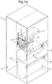
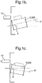
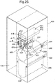
- Fig. 1a illustrates in an exemplary embodiment a reverse vending machine (RVM) 1 exemplifying main aspects of the present invention, i.e. object storage chamber 2; object supporting, rotating, sorting and conveyor unit 3; camera-aided detector device 4; supplementary item/ object collector means 5; token dispenser 6; token reader 7, safety apparatus 8, and drive means 9; 9'.
- the unit 3 (later denoted as 200) could have to have its longitudinal axis 3' horizontal or forming an angle ⁇ with the horizontal, yielding angle ⁇ in the range ⁇ 0° - 30°, as indicated on figs. 1b and 1c .
- the operational means 2 - 9 just mentioned will for practical reasons be denoted by other reference numerals.
- Direction is also made to fig. 25 showing the figure of fig. 1a , however with more reference numerals inserted to identify location of some of the various operational means which are extensively disclosed in the disclosure to follow in connection with figs. 2 - 24
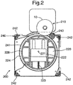
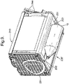
- the drum type conveyor includes a drum shaped element that is rotary about a central, longitudinal axis of rotation 221.
- the movable element is denoted by the numeral 223, and the space or cavity in the drum is denoted by reference numeral 222.
- the rotational capability of the drum 220 is obtained through use of bearings positioned in a region at each end of the drum, and positioned on the axis of rotation 221.
- a part of the structure such as a cabinet, can be adapted to hold the bearings in place, thereby allowing the drum to rotate with its outer surface 228 in proximity to the input receiving area 210 which is made to coincide with an inlet opening 425 (see fig. 25 ) in the cabinet 428 (see fig. 25 ).
- the drum 220 may be positioned in a frame 240 to form a conveyor assembly for easy conveyor assembly removal for convenient conveyor cleaning, test, maintenance and replacement.
- the frame 240 is suitably adapted to match a receiving frame 251 ( fig. 11 ) that preferably is part of a cabinet 428 ( fig. 25 ), and which facilitates any of the possible layouts of a storage facility, as exemplified by several of the previous figures.
- the moveable element 223 is driven by way of a moveable element drive means comprising a tappet or a roller 232, being attached to the moveable element 223, that follows a track 231 located proximal to an end of the drum and being stationary in respect of the drum.
- a moveable element drive means comprising a tappet or a roller 232, being attached to the moveable element 223, that follows a track 231 located proximal to an end of the drum and being stationary in respect of the drum.
- the shape of the track i.e. the distance of the track from the axis of rotation of the drum, controls the position of the tappet or roller 232, and, hence, the position of the moveable element, in a radial direction with respect to the drum center axis.
- the track is a single, continuous track 231 followed by the tappet or roller means 232.
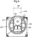
- the drum 220 is shown in a first rotational position with the movable element in an advanced position and pointing downwards, and with a returnable object/ item 10 entered into the input receiving space or area 210 to be placed on an upward facing region of the outer circumferential surface 228 of the drum 220.
- the drum type conveyor includes an elongate roller 243, or other means to allow rotation of the item while keeping the item in the input receiving area, to facilitate a rotation of a returnable object/ item 10 resting on the drum surface 228 as the drum 220 is put into rotation about its axis of rotation 221.
- the drum type conveyor has also a guide 241, e.g. a curved plate member, that extends from the area 210 to the output 224, as will be further explained in connection with fig. 8 . Further guides 241, e.g. as also shown on fig. 8 , could extend from the area 210 down to the output 226'.
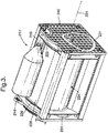
- Fig. 3 depicts in a perspective view the drum 220 in the first rotational position as shown in fig. 2 and with the returnable item 10 resting on an upwardly facing part of the drum circumference.
- the conveyor is provided with a roller driving 244 means for driving the roller 243 in conjunction with driving of the drum, such that the surface velocity of the roller 243 is in a range of a velocity of a rolling surface 228 of the drum when rotated.
- the roller driving means 244 comprises a gear drive arrangement that mechanically provides a rotation of the roller 243 by the rotation of the drum 220.
- Movement in an axial direction of a returnable object/ item 10 being positioned in the input receiving area and resting on the drum 220 and roller 243 is in part restricted by end walls 229 associated with and located at each end of the drum 220, and in part by elements 242 that constitute the frame 240.
- the conveyor shown in fig. 3 can be provided with a single output 224, corresponding to only one particular angular drum rotary position, or with a second output at a different angular rotary position of the drum.
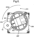
- the drum 220 is shown in a second rotational position with the space or cavity opening in the drum facing the input receiving area, and with the movable element 223 moved to the retracted position.
- This has thereby allowed the returnable object/ item 10, shown in fig. 2 as resting on the circumferential drum surface 228, to fall into the recess-like space or cavity 222, as the drum is rotated to arrive at the second position after rotation from the first position, and be contained by the drum 220.
- the same situation is also shown in the perspective view of fig. 5 , which shows parts of interior side walls of the space 222 and the drum end walls 229, which contribute to restrict a movement of the returnable object/ item 10 such that it may not go beyond the space provided by the cavity 222.
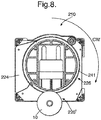
- a partial sectional view of the drum type conveyor shows the drum in a third angular position, where the movable element has been moved in a first and counterclockwise direction from the retracted position shown in figs. 4 and 5 to an advanced position to drive the returnable item to the first output 224, preferably for the purpose of driving the object/ item 10 towards the in-feed opening of a storage chamber 110. If driven in a second and clockwise direction to a second output, which is either output 226 or output 226', but not both, in-feed to a respective storage chamber 112 or 114 could be envisaged.
- the drum type conveyor is provided with said guide 241 to restrict the item 10 to its location in the cavity 222 while the drum is being rotated from the second position with the space 222 facing the input receiving area 210 to the third angular position where the opening of the cavity 222 is facing the first output 224.
- the same situation is also shown in perspective view fig.14 , with the opening of the cavity 222 aligned with the first output 224 and with the movable element 223 in an advanced position.
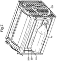
- a partial cross sectional view of the drum type conveyor shows the situation based on the situation shown in fig. 4 , now with the drum rotated in a second and opposite rotational direction (clockwise direction in the example), whereby the returnable object/ item 10 that was received in the space or cavity 222 when the drum was in its second rotational position has been carried by the drum through a rotation of the drum through approximately 180° so that the drum assumes its first position as shown on figs. 2 and 3 .
- the object/ item is driven out from the space 222 by the movable element 223 moving from a retracted position to an advanced position, but also by the effect of gravity.
- a guide241 is provided to restrict the movement of the object/ item 10 when held in the space 222 while the drum is being rotated from the second rotational position with the space facing the input receiving area 210 to the first rotational position with the opening of the space 222 and the curved face 223' of the element 223 being in register with the output 226'.
- the situation of fig. 8 is also shown in the perspective view from below of fig. 9 , with the item 10 exiting from the conveyor at the alternative output 226'.
- the drum For conveying an item 10 that has entered the recess-like space or cavity to one out of two possible outputs in a specific embodiment of the combined drum conveyor and sorter, different directions of rotation can be used.
- the drum would be rotated in a first direction (e.g. counterclockwise, as shown) to deliver the item at the first output 224, while a rotation in a second direction (e.g. clockwise, as shown) would be applied to the drum for delivering the item 10 at a second output 226 or 226'.
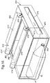
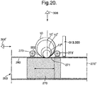
- fig. 10 shows a first example of a substantially linearly moveable plunger in a stationary housing type conveyor, as comprising an elongated housing 260 with an input opening 262 on one side adapted to face the input receiving area 210 of the storage facility, an interior space 261, a substantially linearly movable plunger or slide member 270, a first output 263 and a second output 264.
- the housing may be designed to be curved in any direction to allow an output in an arbitrarily chosen angle.
- an elongated slot 272 in one side of the housing which is provided as an access means for allowing a plunger drive means (not shown) to be attached to the plunger 270 for positioning of the plunger in different parts of the interior space 261.
- a plunger drive means (not shown) to be attached to the plunger 270 for positioning of the plunger in different parts of the interior space 261.
- Such a slot can be provided at any longitudinally extending side of the housing, and also at more than one side to provide a balanced drive force to the plunger.
- a returnable object/ item 10 which has been positioned in the input receiving area, and which by the aid of gravity and the provision of the input opening 262 will fall into the interior space 261 of the housing, and thereby become located adjacent to the plunger 270 when the plunger initially has been positioned in a first position which is below the opening 262.
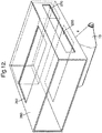
- the conveyor suitably includes an item turning device, preferably using at least one roller 273 or preferably two rollers 273, 273' if two outputs 263, 264 are two be used.
- the device is located adjacent the input opening 262.
- the upper side face 271 of the plunger i.e. the side of the plunger that will be facing the input opening 262, has a surface structure that is specially prepared to provide good friction against a returnable object/ item 10 that has been deposited in the input receiving area and brought to rest on the upper side face 271 of the plunger.
- a rotation of the object/ item 10 that rests on the upper side face 271 of the plunger 270 is then obtainable by movement of the plunger 270 while the object/ item 10 is resting on top of the plunger 270, which rotation is further augmented by the rollers 273, 273'.
- the rollers 273, 273' also cause the object/ item 10 to not move away from the opening 262 while rotated or if the longitudinal axis 260' (see figs. 11 and 13 ) of the housing forms an angle with the horizontal.
- the upper side face 271 of the plunger 270 can be extended in any direction of movement of the plunger 270, to obtain a desired range of turning of the item 10 that rests on the upper side face 271 of the plunger 270.
- roller 273 a preferred embodiment of the plunger type conveyor and sorter has two rollers 273, 273 , one at each side of the input opening 262, to facilitate rotation of the item 10 in any direction in connection with a movement of the plunger 270 in the longitudinal direction of the housing 260.
- the rollers are rotatably supported at each end by mountings 275.
- the rollers 273; 273' can be freely rotatable, or they can be driven by a driver arrangement 274 by way of a separate drive means or by a linkage to the plunger 270 or the driver for the plunger.
- the drive means 274; 274' e.g.
- any roller arrangement 273 can include a load cell 276 suitably supporting the roller at one end thereof in order to measure a reaction force exerted on the roller as a function of an acceleration or turning of the object/ item 10 due to movement of the plunger 270, or a reaction force due to the weight of the item 10, in particular if longitudinal axis of the housing 260 is made to tilt, e,g. in the range of ⁇ 0° - 30° relative to the horizontal..
- the plunger 270 will then upon movement in an opposite direction apply a driving force to the object/ item 10 to drive it towards and through e.g. the first output 263 if the plunger at first had moved away from the opening 262 towards output 264, or towards and through e.g. the second output 264 if the plunger had at first moved away from the opening 262 towards output 263.
- the plunger 270 would preferably force the item, towards an in-feed opening of a storage chamber of a storage facility as disclosed herein.
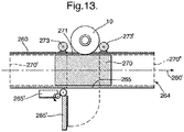
- the third output 265 includes a closing means 265' which is shown on fig. 13 , but not on fig. 12 .
- the closing means 265 is capable of controllably blocking the output 265 such that an object/ item 10 that has entered the interior space 261 of the housing 260 selectively can be kept from exiting the housing through the output 265 if the object/ item 10 is instead to be directed towards a different output, e.g. output 263 or 264.
- the means 265' for selectively closing the third output 265 can be made operational by way of a separate driver or actuator 265", e.g.
- a solenoid or by a linkage to the plunger 270, for example by placing the output in an open state when the plunger is placed in an extreme position within the housing, such as for example in connection with a movement of the plunger beyond the position of the plunger 270 as shown in e.g. on fig. 12 .
- the object/ item 10 is allowed to pass through the opening 262, the interior of the housing 260 and then exit through the opening 265.
- the exit of the item 10 after having traveled straight through the housing from the input 262 to the output 265 is shown in fig. 12 .
- Fig. 14 illustrates how the plunger 270 may be used to rotate the object / item 10. , e.g. a bottle, by moving the plunger either way, the rollers 273, 273' assisting a safe and efficient rotation of the item 10.
- the understanding of fig. 14 as regards rotation of the item 10 before it enters into the interior 261 of the housing 260 will be the same, irrespective of the presence of the output 265.
- the three-outputs embodiment could be made instead as a two-outputs embodiment, having e.g. outputs 263 and 264, outputs 263 and 265 or outputs 264 and 265.
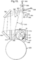
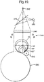
- Fig. 15 depicts a first light source 300 and a second light source 301, the light source 301 suitably consisting of a plurality of light sub-sources 302, 303, 304, 305.
- the light sources 300 and 301 are separately configured to illuminate a first region 306 and a second region 307 of an object, e.g. a returnable item 10;10';10",10"'.
- a single camera 308 is provided to view at least part of the regions 306 and 307.
- the first light source 300 is configured to assist the camera 308 in viewing of contour of objects, items or articles 10, 10', 10", 10"' of different cross section, e.g.
- the light from the first light source 300 is directed towards the object (e,g. one of those labeled 10 through 10"' ) as parallel light using a lens 314.
- the second light source 301 is configured to assist camera viewing by the camera 308 for detection and recognition of any identity features located on the object in viewing sector labeled 315.
- Said identity features are suitably at least one of: bar code, graphic symbol and alphanumeric characters.
- the invention also offers a substantial advantage over a two-camera solution.
- the camera sensor matrix When a camera views e.g. an object contour or identifying features thereon, the camera sensor matrix provides a string of matrix pixel signals to be processed in order to identify or recognize such contour or features, including the possibility of letting the camera read and causing identification of e.g. a bar code.
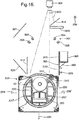
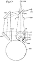
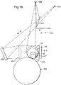
- the first light source 300 illuminates the first region 306 via a light path which includes an optical beam splitter (or view splitter) 316 ( figs. 15 and 16 ), 318 ( fig. 17 ) or 319 ( fig. 18 ), at least one inclined mirror 320 and the lens 314.
- an optical beam splitter or view splitter
- 316 figs. 15 and 16
- 318 fig. 17
- 319 fig. 18
- Figs. 15 , 16 and 18 depict a light beam splitter 316; 319 located in an inclined posture in the camera field of view 322 and covers at least part of said field of view, suitably approximately half of the camera field of view.
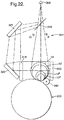
- Fig. 17 depicts an optical beam splitter 318 which covers the complete camera field of view.
- an optical beam splitter 316 or 319 which is within only half or less of the camera field of view
- the splitter is suitably assisted by a vision blocker 323; 324 to prevent the camera from viewing both directly in the sector 315 and through the splitter, the splitter providing a less clear viewing. If the vision blocker 323; 324 is omitted, then the camera will be able to view the entire region 307.
- Fig. 17 shows the camera in a configuration set to view the second region 307 completely via the beam splitter 318. This implies that the camera 308 views either the first region 306 via the splitter, the mirrors 321, 320 and the lens 314, and secondly the second region 307 through the splitter. In this latter situation, the light source 301 is fully or partly activated, and the light source 300 is deactivated.
- the light source 301 suitably comprising a plurality of light sub-sources 302 - 305, is notably located in a region between the beam splitter 316; 318; 319 and an object supporting means in the form of said compact conveyor and sorter 200.
- the object supporting means 200 is shown only schematically, but in more detail on fig. 16 .
- a more detailed operation of the object supporting means 200 and a possible, schematically shown alternative on fig. 32, is disclosed in the preceding disclosure of figs. 1-24 .
- said supporting means is in the form of the rotary drum 220 (see fig. 16 ) with the auxiliary roller 243.
- the drum 220 and the roller 243 will controllably, but forcibly rotate the object 10 on a portion 220' or 220" of the circumference of the drum.
- the drum 220 has at least one radial inwardly directed, adjustable space or cavity 222 for receiving the object 10 after its rotation on said circumference portion and for transporting the object 10 through rotation of the drum to an output location, e.g.
- the camera 308 will be able to view and cause detection of the presence of the object 10 when it has dropped into the adjustable space 222.
- This has a safety function aspect and also a security function aspect., i.e. to prevent any swindle attempt. This means that the drum 220 will not start turning until the camera 308 actually observes and causes detection of the object being present in the space 222 and with the movable element 223 operating as a movable bottom in its fully retracted state.
- the direction which the drum will then turn is determined by set criteria which are compared to recognize characteristic features of the object. Further, in case the contour of the object is to be viewable from above, rather than sideways, it would be advantageous to let at least a part of the rotary drum 220 be provided with a coating which is retro-reflective to light, in particular at the portions labeled 220' and 220" of the drum 220. Such a situation is in particular suitable in connection with the example shown on fig. 19 and will be further explained later.
- the single camera is generally denoted by 308, 308', the reference 308' symbolizing viewing by the camera 308 via e.g. a beam splitter 318 and mirrors 321, 320 (see fig. 17 ).
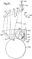
- Said supporting means is suitably in the form of the housing 260 forming a guide with an object receiving input opening 262 and a reciprocating plunger or 270 therein.
- auxiliary roller 273; 273' for roller support upon rotation of the object or item 10; 10'; 10"; 10"' on the plunger 270 when it is set to move with its upper surface 271 past said opening, thus enabling the camera 308 to read an identifying feature on the object or item 10 if not immediately viewable by the camera.
- the plunger 270 is controllable to move beyond said opening 262, e.g. to the position shown by dotted lines 270" to allow the object to drop into the interior of the housing 260 through said opening 262 and by return movement of the plunger 270 (towards left as shown on fig. 22 ) causing the object to be pushed out of the housing to an output location 263.
- the object 10 is camera observable while at a location inside said housing 260 below said opening 262, provided that such location is in at least part of a field of view of the camera 308.
- at least at the upper part 271 of the plunger 270 can be provided with a coating retro-reflective to light, thus enabling the contour of the object, e.g. 10, to be viewed from above.
- Fig. 19 shows the use of a single camera 340 and with an optical beam splitter 341 inclined relative to a lens 343.
- a light source 342 provides for illumination of the object, e.g. 10, through lens 343 to provide parallel light rays towards the supporting means 200, which has its drum parts 220' and 220" (see fig. 26) provided with retro-reflective material or property enabling light not hit by the object to be retro-reflected back to camera 340 via the lens 343 and the splitter 341 to provide an image of the contour of the object.
- a light source 344 is activated, the light source suitably being of the same type as the light source 301.
- light source 342 may be deactivated, if required.
- Figs. 15 -18 clearly demonstrate that the first and second regions 306, 307 are partly overlapping, and fig. 19 indicates full overlapping.
- Fig. 21 is identical to the embodiment shown on fig. 15 , apart from the light source 300 and the retro-reflective background 313 having been deleted and replaced by a light emitting, illuminated or backlit panel 350, the panel 350 thus forming a bright background.
- Ambient light may in some applications be sufficient in order that the camera views a bright background.
- the panel 350 will provide the bright background against which e.g. the object 10 is to be viewed by the single camera 308.
- FIG. 22 A similar situation is present with the embodiment of fig. 22 , which is identical to the embodiment shown on fig. 17 , apart from the light source 300 and the retro-reflective background area 313 having been deleted and replaced by a light emitting area, suitably in the form of the panel 350 to form a bright background against which e.g. the object 10 is to be viewed by the single camera 308 to provide for e.g. detection of object contour.
- the first and second light sources e.g. 300, 301; 300', 301; 342, 344; 348, 349; 350, 301; 350, 354; 350, 349; 350, 359 have different spectral range or composition.
- the second light sources 301; 344; 349; 359 composed of two or more sub-sources.
- the sub-sources could have different spectra range or composition, either all different, different in pairs or in groups.
- Such features of the light sources and possible sub-sources are of importance to be able to detect e.g. identifying features on the objects appearing e.g. with different colours, different reflective properties etc.
- Camera viewing of the first region of the object 362 related to its contour 363 can in addition include observation or rather recognition of mere presence or absence of said identifying features 364, e.g. bar code located on the object.
- the focus of the camera will not be exactly on the features 364, but the camera will at least sense or detect with relation to the partial image 360 whether the features 364, here labeled 364' are indeed present or not, although on the partial image 360 appearing "blurred” or a bit out of focus. If the features 364 are not visible on the image part 361, but visible on part 360, this will indicate necessity to rotate the object one way or the other through a maximum angle of 180°.
- the comparison between the two images 360 and 361 in this respect has some impact on the required amount of rotation of the object in order to be able to view and read the feature 364 properly in region 307, and consequently has also importance with regard to processing time in order to find the feature 364, read and record it.
- the camera has preferably, but not necessarily its image field subdivided into said at least two partial images 360, 361, the first partial image 360 being dedicated to object contour detection and/ or detection of presence or absence of said identifying features, and the second partial image 361 being dedicated to observation and reading of said identifying features.
- Fig. 24 depicts an overall system in which the various aspects of the present invention are implemented.
- the reverse vending machine has said processing and control unit 400 which receives video data from the camera 401 via a video analyzer 402.
- the camera 401 is also linked to the operation unit 408, and the operation unit includes the watchdog timer 403 and a motor control.
- the motor #1 and its control, denoted 404 are related to the drive of the supporting means 325, 327, or the unit 333 as disclosed earlier.
- a motor overload sensor 405 is also provided to inhibit operation of motor #1 in case of jam not detected by the operational unit 408 or a jam detector 406.
- the sensor 405 could be in the form of a pressure sensitive bar, or the roller 243 could have its weight sensor 253 (in fig. 24 denoted by 419) modified in order to also indicate pressure against the roller caused by a jam due to an object not fully located in the recess or space 222.
- the operation unit 408 is, as disclosed earlier linked with the camera 401 and the processing and control unit (processor) 400, and in the present example the unit 408 controls the motor controls 404 and 422 directly, although such control could be via the processor 400.
- optically readable cards will normally be read by e.g. camera 401. However, if a card is a magnetic readable/ writable card or an r.f. readable/ writable card, there will be the need of a card reader / card encoder unit 411.
- the tokens are ready made, pre-coded cards, like the cards 367 which are dispensable one by one from the dispenser means 369; 412 (fig. 46 ) and which upon the feed-out from the dispenser 412 via output 412' is code-read by a code reader/ encoder 411, in particular if the card is a magnetic stripe or r.f. card. Alternatively, if the card is an optically readable card, the card is read by the camera 401 via aperture 424 and inclined mirror 424').
- the code reader/ encoder 411 will be able to encode the card with a card code, such as e.g. a serial number or other identity, or the combination of a card code or serial number or other identity and a redemption value to be rewarded or paid, as the cards are fed out from the dispenser one-by-one.
- a card code such as e.g. a serial number or other identity, or the combination of a card code or serial number or other identity and a redemption value to be rewarded or paid, as the cards are fed out from the dispenser one-by-one.
- such token could be a personal token which the customer brings with him to the RVM and uses to transfer card identity data from the card to the RVM.
- the card is an optically readable card, it can be read by the camera 401 and as indicated further by reference 411' when inserted into a slot (see reference 370; fig. 16 ) and viewable through an aperture (see reference 370'; fig. 16 ) in the light retro-reflective area (see reference 313; fig. 16 ).
- the card is an r.f. readable card, the card could be readable by an r.f. reader 411"
- the card could be readable by a magnetic stripe readable card, the card could be readable by a magnetic stripe reader 411"'.
- the cards could be in the form of a reusable token, in particular because the cards are in any case validated and after reward has been paid, invalidated.
- the token could be retrieved from a stack or a band of cards. If a band of cards or a zig-zag arranged band of cards is used, the dispenser 369 (412 on fig. 24 ) should suitably be replaced by a conventional type of dispenser for such card arrangement. Also, different type of encoder 411 may be required. In any case, the card should have at least an alphanumerical, machine readable code.
- the token is a card which is optically readable
- the card should have a pre-made code thereon, suitably consisting of a bar code or other optically readable code readable by an optical reader such as the camera 401.
- the bar code or other optically readable code is preferably retro-reflective to light.
- the card could be made of a retro-reflective material and the bar code be made of a non-reflective material.
- the processor 400 will either directly, or via a central computer installation 413 transfer to a rewarding or check-out and payment station 414 information related to a readable token code and information related to said return value. Transfer of information to and from the processor to the computer 413 and the station 414 is suitably via a local area network (LAN) 415.
- the station 414 has a card reader 416 to read the card before reward or redemption value is paid. The card is then invalidated through use of a token invalidation means 407 associated with the station 414 or through internal operation in the unit 400 and/ or the computer 413.
- the processor 400 communicates with a "tick-off" unit 417, which could be in the form of a minicomputer, such as so-called PDA.
- the RVM has suitably a display 418 to properly guide or inform an RVM user how to operate. If the display is a touch screen, the customer may communicate with the processor 400.
- the container weight sensor 419 indicated on fig. 24 is provided to engage an end 247 of an axle 243' (see fig. 16 ) of the roller 243, so as to spot whenever a too heavy beverage container is fed into the RVM through an opening 425 on the RVM.
- the term "too heavy” in this context is meant to imply that the unit 400, upon receiving information related to shape and identity features, will compare these data with library data in the unit 400, and thereby determine whether the object in fact should weigh less or not. This has been disclosed in more detail earlier. Also as indicated, the weight sensor could suitably form or supplement the jam sensor 405.
- An interlock-mechanism 420 is provided for safety reasons.
- the mechanism is suitably a set of sensors and switches to ensure that the RVM cannot be operated unless all units are in proper place and all cabinet panels are in proper mounted position and cabinet doors are locked.
- a power supply 421 is provided, suitably linked to power consuming units via the unit 400.
- a motor and control unit 422 is provided to cause the volume of a collection container 426 to be adjusted by winding or unwinding a flexible side and bottom 426'.
- fig. 25 shows a collection container 426, it would be understood by the average expert in the art that other operational equipment could be installed and operated instead of the collection container.
- Such equipment could include one or more from the group of: conveyor; pusher unit; rotation means; compactor; disintegrator; sorter means.
- the positioning and evidently the configuration of such equipment in cooperation with the motor 422 could be substantially different from that of the collection container 426.
- the collection container is particularly suitable for heavier objects, e.g. bottles of glass.
- Reference numeral 423 in fig. 24 denotes a position sensor which is used to detect rotary positions of the drum 220, or the plunger 270.
- the reference numeral 100 denotes generally a storage compartment for receiving objects delivered from the supporting, sorting, conveying and push-out unit 200. .
Landscapes
- General Physics & Mathematics (AREA)
- Physics & Mathematics (AREA)
- Health & Medical Sciences (AREA)
- Life Sciences & Earth Sciences (AREA)
- Chemical & Material Sciences (AREA)
- Analytical Chemistry (AREA)
- Biochemistry (AREA)
- General Health & Medical Sciences (AREA)
- Immunology (AREA)
- Pathology (AREA)
- Control Of Vending Devices And Auxiliary Devices For Vending Devices (AREA)
- Sorting Of Articles (AREA)
- Refuse Collection And Transfer (AREA)
- Warehouses Or Storage Devices (AREA)
- Vending Machines For Individual Products (AREA)
- Discharge Of Articles From Conveyors (AREA)
- Telephone Function (AREA)
- Specific Conveyance Elements (AREA)
- Looms (AREA)
- Spinning Or Twisting Of Yarns (AREA)
- Telephonic Communication Services (AREA)
- Length Measuring Devices By Optical Means (AREA)
Claims (13)
- Gerät, um das Prüfen charakteristischer Merkmale eines Objekts (10, 10', 10", 10"') durch eine Kamera zu ermöglichen, um nachfolgend das Verarbeiten von Signalen zu ermöglichen, welche die geprüften Merkmale betreffen, gekennzeichnet durch:- eine einzelne Kamera (308) mit einem Bildfeld, die dafür angeordnet ist, das Prüfen mindestens eines ersten (306) und eines zweiten (307) Bereichs des Objekts auszuführen, wenn sich das Objekt an einer Betrachtungsposition befindet,- eine erste Lichtquelle (300; 350), die dafür angeordnet ist, den ersten Bereich (306) des Objekts (10, 10', 10", 10"') zu beleuchten, um die Kamera beim Prüfen des Umrisses des Objekts zu unterstützen, und- einen optischen Strahlteiler, wobei die erste Lichtquelle dafür angeordnet ist, den ersten Bereich über einen Lichtweg zu beleuchten, der den optischen Strahlteiler, mindestens einen Spiegel und eine Linse beinhaltet,- eine zweite Lichtquelle (301; 302 - 305), die dafür angeordnet ist, den zweiten Bereich (307) des Objekts (10, 10', 10", 10"') zu beleuchten, um die Kamera beim Prüfen eines am Objekt angeordneten Identitätsmerkmals zu unterstützen,wobei der optische Strahlteiler geneigt im Kamerabildfeld angeordnet ist und nur einen Teil des Bildfeldes abdeckt,
wobei die Kamera ein Bildfeld bereitstellt, das in mindestens zwei Teilbilder unterteilt ist, wobei ein erstes Teilbild der Erkennung eines Objektumrisses zugeordnet ist und ein zweites Teilbild der Wiedererkennung der Identitätsmerkmale zugeordnet ist,
wobei der erste Bereich durch die Kamera geprüft wird, wobei die Sichtlinie hin zum Objekt im Verhältnis zur Sichtlinie der Kamera hin zum zweiten Bereich um 90°±30° versetzt ist. - Gerät, um das Prüfen charakteristischer Merkmale eines Objekts (10, 10', 10", 10"') durch eine Kamera zu ermöglichen, um nachfolgend das Verarbeiten von Signalen zu ermöglichen, welche die geprüften Merkmale betreffen, gekennzeichnet durch:- eine einzelne Kamera (308) mit einem Bildfeld, das dafür angeordnet ist, das Prüfen mindestens eines ersten (306) und eines zweiten (307) Bereichs des Objekts auszuführen, wenn sich das Objekt an einer Betrachtungsposition befindet,- eine erste Lichtquelle (300; 350), die dafür angeordnet ist, den ersten Bereich (306) des Objekts (10, 10', 10", 10"') zu beleuchten, um die Kamera beim Prüfen des Umrisses des Objekts zu unterstützen, und- wobei die erste Lichtquelle eine lichtemittierende, beleuchtete oder hinterleuchtete Tafel (350) ist, die, von der Kamera aus betrachtet, hinter dem Objekt angeordnet ist,einen optischen Strahlteiler, wobei die einzelne Kamera dafür angeordnet ist, den ersten Bereich über einen Lichtweg zu prüfen, der den optischen Strahlteiler, mindestens einen Spiegel und eine Linse beinhaltet,- eine zweite Lichtquelle (301; 302 - 305), die dafür angeordnet ist, den zweiten Bereich (307) des Objekts (10, 10', 10", 10"') zu beleuchten, um die Kamera beim Prüfen eines am Objekt angeordneten Identitätsmerkmals zu unterstützen,wobei der optische Strahlteiler geneigt im Kamerabildfeld angeordnet ist und nur einen Teil des Bildfeldes abdeckt,
wobei die Kamera ein Bildfeld bereitstellt, das in mindestens zwei Teilbilder unterteilt ist, wobei ein erstes Teilbild der Erkennung eines Objektumrisses zugeordnet ist und ein zweites Teilbild der Wiedererkennung der Identitätsmerkmale zugeordnet ist,
wobei der erste Bereich durch die Kamera geprüft wird, wobei die Sichtlinie hin zum Objekt im Verhältnis zur Sichtlinie der Kamera hin zum zweiten Bereich um 90°±30° versetzt ist. - Gerät nach Anspruch 1 oder 2, wobei das Licht von der ersten Lichtquelle (300; 350) einen Spektralbereich oder eine Spektralzusammensetzung aufweist, der/die sich von dem/der des Lichts von der zweiten Lichtquelle (301; 302 - 305) unterscheidet.
- Gerät nach einem der Ansprüche 1 - 3, wobei die zweite Lichtquelle (301; 302 - 305) aus mehreren Teilquellen zusammengesetzt ist und wobei den Teilquellen unterschiedliche Spektralbereiche oder Spektralzusammensetzungen derart zugeordnet sind, dass sich alle Teilquellen unterscheiden sind oder dass sich die Teilquellen in Paaren unterscheiden oder dass sich die Teilquellen in Gruppen unterscheiden.
- Gerät nach Anspruch 1, wobei das Prüfen des ersten Bereichs (306) durch die einzelne Kamera (308) über den optischen Strahlteiler (316; 318; 319) und den mindestens einen Spiegel (320; 321) erfolgt.
- Gerät nach einem der Ansprüche 1 - 5, wobei die Kamera (308) dafür konfiguriert ist, den zweiten Bereich (307) außerhalb einer Position des optischen Strahlteilers (316; 319) zu prüfen.
- Gerät nach Anspruch 1, wobei der erste Bereich durch die Kamera gegen einen hellen Hintergrund (313; 350) prüfbar ist, der durch die erste Lichtquelle (300; 350) bereitgestellt ist.
- Gerät nach einem der Ansprüche 1 - 7, wobei die Kamera (308) beim Prüfen des ersten Bereichs (306) bezüglich der Objektumrisserkennung zusätzlich dafür konfiguriert ist, eine Erkennung des Vorhandenseins oder Nichtvorhandenseins der am Objekt angeordneten identifizierenden Merkmale bereitzustellen.
- Gerät nach einem der Ansprüche 1 - 8, wobei der Hintergrundbereich (313; 350) in sich eine Öffnung (365) aufweist, um es der Kamera (308) zu ermöglichen, eine beleuchtete Markierung (366) auf einem Zeichen (367) zu lesen, das angrenzend an eine Rückseite des Hintergrundbereichs (313; 350) angeordnet ist, wobei das Zeichen (367) in einer gesteuerten Weise von einer Zeichenausgabeeinheit (369) auszugeben ist und mindestens ein betrachtetes Objekt (10, 10', 10", 10"') betrifft, das durch Trägermittel getragen wird.
- Gerät nach Anspruch 9, wobei die Markierung (366) auf dem Zeichen (367) aus einem der Folgenden besteht: einem lichtreflektierenden Material, einem retroreflektierenden Material und einem nicht reflektierenden Material auf einem reflektierenden Material des Zeichens.
- Gerät nach Anspruch 9 oder 10, wobei die Markierung (366) über einen geneigten Spiegel (368), der angrenzend an die Öffnung (385) in dem lichtemittierenden oder hellen Hintergrundbereich (313; 350) angeordnet ist, durch die Kamera lesbar ist.
- Gerät nach einem der Ansprüche 1 - 11, wobei die einzelne Kamera (308) dafür konfiguriert ist, den ersten und den zweiten Bereich (306; 307) durch abwechselndes Prüfen oder selektives Prüfen oder gleichzeitiges Prüfen zu prüfen.
- Gerät nach einem der Ansprüche 1 - 12, wobei die zweite Lichtquelle (301; 302 - 305) mehrere lichtbereitstellende Teilquellen umfasst, von denen zumindest einige Licht in einem Spektralbereich bereitstellen, der sich von dem Spektralbereich des Lichts unterscheidet, das von einer oder mehreren der verbleibenden lichtbereitstellenden Teilquellen (302 - 305) bereitgestellt wird.
Applications Claiming Priority (9)
| Application Number | Priority Date | Filing Date | Title |
|---|---|---|---|
| NO20050406 | 2005-01-25 | ||
| NO20050402A NO20050402D0 (no) | 2005-01-25 | 2005-01-25 | Deteksjonsanordning |
| NO20050404 | 2005-01-25 | ||
| NO20050405 | 2005-01-25 | ||
| NO20050403 | 2005-01-25 | ||
| NO20050407 | 2005-01-25 | ||
| NO20050401A NO20050401D0 (no) | 2005-01-25 | 2005-01-25 | Kamera-assistert anordning for a betrakte et objekt |
| EP06701103.1A EP1842169B1 (de) | 2005-01-25 | 2006-01-24 | Mittel in einem rücknahmeautomaten für die entgegennahme, behandlung, sortierung von mehrwegobjekten |
| PCT/NO2006/000029 WO2006080851A2 (en) | 2005-01-25 | 2006-01-24 | Means in a reverse vending machine (rvm) for receiving, handling, sorting and storing returnable items or objects |
Related Parent Applications (2)
| Application Number | Title | Priority Date | Filing Date |
|---|---|---|---|
| EP06701103.1A Division EP1842169B1 (de) | 2005-01-25 | 2006-01-24 | Mittel in einem rücknahmeautomaten für die entgegennahme, behandlung, sortierung von mehrwegobjekten |
| EP06701103.1A Division-Into EP1842169B1 (de) | 2005-01-25 | 2006-01-24 | Mittel in einem rücknahmeautomaten für die entgegennahme, behandlung, sortierung von mehrwegobjekten |
Publications (2)
| Publication Number | Publication Date |
|---|---|
| EP1947615A1 EP1947615A1 (de) | 2008-07-23 |
| EP1947615B1 true EP1947615B1 (de) | 2018-09-26 |
Family
ID=36609269
Family Applications (8)
| Application Number | Title | Priority Date | Filing Date |
|---|---|---|---|
| EP08152913.3A Expired - Lifetime EP1947614B1 (de) | 2005-01-25 | 2006-01-24 | Förderbandmittel für zurücksendbare Elemente |
| EP08152917.4A Expired - Lifetime EP1947616B1 (de) | 2005-01-25 | 2006-01-24 | Sicherheitsvorrichtung zum Steuern des Betriebs der Funktionsausrüstung mit beweglichen Teilen |
| EP08152912.5A Expired - Lifetime EP1947613B1 (de) | 2005-01-25 | 2006-01-24 | Drehförderband für Pfandgegenstände |
| EP20080152921 Withdrawn EP1947618A1 (de) | 2005-01-25 | 2006-01-24 | Treibervorrichtung in einem Rücknahmeautomat |
| EP19151910.7A Expired - Lifetime EP3499471B1 (de) | 2005-01-25 | 2006-01-24 | Mittel in rücknahmeautomaten zum aufnehmen, handhaben, sortieren und aufbewahren von rückgabeartikeln oder -objekten |
| EP06701103.1A Expired - Lifetime EP1842169B1 (de) | 2005-01-25 | 2006-01-24 | Mittel in einem rücknahmeautomaten für die entgegennahme, behandlung, sortierung von mehrwegobjekten |
| EP08152919.0A Expired - Lifetime EP1947617B1 (de) | 2005-01-25 | 2006-01-24 | Markensystem zur Installation in einem umgekehrten Verkaufsautomaten |
| EP08152915.8A Expired - Lifetime EP1947615B1 (de) | 2005-01-25 | 2006-01-24 | Vorrichtung für eine Kameraansicht eines Objekts |
Family Applications Before (7)
| Application Number | Title | Priority Date | Filing Date |
|---|---|---|---|
| EP08152913.3A Expired - Lifetime EP1947614B1 (de) | 2005-01-25 | 2006-01-24 | Förderbandmittel für zurücksendbare Elemente |
| EP08152917.4A Expired - Lifetime EP1947616B1 (de) | 2005-01-25 | 2006-01-24 | Sicherheitsvorrichtung zum Steuern des Betriebs der Funktionsausrüstung mit beweglichen Teilen |
| EP08152912.5A Expired - Lifetime EP1947613B1 (de) | 2005-01-25 | 2006-01-24 | Drehförderband für Pfandgegenstände |
| EP20080152921 Withdrawn EP1947618A1 (de) | 2005-01-25 | 2006-01-24 | Treibervorrichtung in einem Rücknahmeautomat |
| EP19151910.7A Expired - Lifetime EP3499471B1 (de) | 2005-01-25 | 2006-01-24 | Mittel in rücknahmeautomaten zum aufnehmen, handhaben, sortieren und aufbewahren von rückgabeartikeln oder -objekten |
| EP06701103.1A Expired - Lifetime EP1842169B1 (de) | 2005-01-25 | 2006-01-24 | Mittel in einem rücknahmeautomaten für die entgegennahme, behandlung, sortierung von mehrwegobjekten |
| EP08152919.0A Expired - Lifetime EP1947617B1 (de) | 2005-01-25 | 2006-01-24 | Markensystem zur Installation in einem umgekehrten Verkaufsautomaten |
Country Status (16)
| Country | Link |
|---|---|
| US (5) | US7997417B2 (de) |
| EP (8) | EP1947614B1 (de) |
| JP (6) | JP5015011B2 (de) |
| CY (1) | CY1121574T1 (de) |
| DK (4) | DK1842169T3 (de) |
| ES (7) | ES3025744T3 (de) |
| FI (1) | FI3499471T3 (de) |
| HR (1) | HRP20190701T1 (de) |
| HU (2) | HUE044105T2 (de) |
| LT (1) | LT1842169T (de) |
| NO (7) | NO343497B1 (de) |
| PL (2) | PL1947614T3 (de) |
| PT (1) | PT1842169T (de) |
| RS (1) | RS58668B1 (de) |
| SI (1) | SI1842169T1 (de) |
| WO (1) | WO2006080851A2 (de) |
Families Citing this family (102)
| Publication number | Priority date | Publication date | Assignee | Title |
|---|---|---|---|---|
| EP1947614B1 (de) * | 2005-01-25 | 2018-10-10 | Tomra Systems ASA | Förderbandmittel für zurücksendbare Elemente |
| US20070174071A1 (en) | 2006-01-20 | 2007-07-26 | C&C Acquisition, Llc | Techniques for managing information relating to recyclable containers |
| US20070276686A1 (en) * | 2006-01-20 | 2007-11-29 | Count & Crush, Llc | Techniques for processing recyclable containers |
| EP1975891A1 (de) * | 2007-03-28 | 2008-10-01 | Wincor Nixdorf International GmbH | Vorrichtung und Verfahren zur Rücknahme von Gebinden |
| GB2449213B (en) | 2007-05-18 | 2011-06-29 | Kraft Foods R & D Inc | Improvements in or relating to beverage preparation machines and beverage cartridges |
| EP2232197A4 (de) * | 2007-11-07 | 2014-04-02 | Tomra Systems Asa | Vorrichtung, optische einheit und einrichtungen zur verwendung bei der detektion von objekten |
| DE102008006382A1 (de) | 2008-01-29 | 2009-07-30 | Wincor Nixdorf International Gmbh | Erkennung von Material und Füllzustand von Leergutbehältern |
| US11264124B2 (en) | 2008-02-20 | 2022-03-01 | Chudy Group, LLC | System and apparatus for item management |
| US8380346B2 (en) | 2008-02-20 | 2013-02-19 | Chundy Group, LLC | System and apparatus for item management |
| US8200533B2 (en) * | 2008-10-02 | 2012-06-12 | ecoATM, Inc. | Apparatus and method for recycling mobile phones |
| US11010841B2 (en) | 2008-10-02 | 2021-05-18 | Ecoatm, Llc | Kiosk for recycling electronic devices |
| US7881965B2 (en) | 2008-10-02 | 2011-02-01 | ecoATM, Inc. | Secondary market and vending system for devices |
| US10853873B2 (en) | 2008-10-02 | 2020-12-01 | Ecoatm, Llc | Kiosks for evaluating and purchasing used electronic devices and related technology |
| US9881284B2 (en) | 2008-10-02 | 2018-01-30 | ecoATM, Inc. | Mini-kiosk for recycling electronic devices |
| CN105303699B (zh) | 2008-10-02 | 2018-10-09 | 埃科亚特姆公司 | 针对设备的二手市场和自动售货系统 |
| JP5359635B2 (ja) * | 2008-12-11 | 2013-12-04 | 富士電機株式会社 | 賞味期限読取装置 |
| DE102009026160A1 (de) | 2009-07-13 | 2011-01-27 | Wincor Nixdorf International Gmbh | Vorrichtung und Verfahren zum Erkennen von charakteristischen Merkmalen eines Leergutbehälters |
| WO2011066839A1 (en) * | 2009-12-04 | 2011-06-09 | Anker Andersen A/S | Reverse vending system for batch registration of used beverage containers |
| US9098959B2 (en) * | 2010-01-12 | 2015-08-04 | Robert Baric | Multi-sided vending machine |
| US9105144B2 (en) | 2010-01-12 | 2015-08-11 | Robert J. Baric | Multiple-sided vending machine |
| WO2011089013A1 (de) * | 2010-01-25 | 2011-07-28 | Wincor Nixdorf International Gmbh | Vorrichtung und verfahren zum erkennen von charakteristischen merkmalen eines leergutbehälters |
| US20110245965A1 (en) * | 2010-03-31 | 2011-10-06 | Farrell Patrick A | Method and Apparatus for Procurement and Resale of New and Used Media |
| US8538581B2 (en) * | 2010-09-03 | 2013-09-17 | Redbox Automated Retail, Llc | Article vending machine and method for authenticating received articles |
| DE102010037448A1 (de) * | 2010-09-10 | 2012-03-15 | Wincor Nixdorf International Gmbh | Verfahren und Vorrichtung zur Erfassung von Leergutbehältern |
| US9792104B2 (en) | 2010-11-05 | 2017-10-17 | FedEx Supply Chain Logistics & Electronics, Inc. | System and method for flashing a wireless device |
| US9575973B2 (en) | 2010-11-05 | 2017-02-21 | Atc Logistics & Electronics, Inc. | System and method for systematically removing customer personal information from an electronic device |
| US9311488B2 (en) | 2010-11-05 | 2016-04-12 | Atc Logistics & Electronics, Inc. | System and method for removing customer personal information from an electronic device |
| US9495367B2 (en) * | 2010-11-05 | 2016-11-15 | Atc Logistics & Electronics, Inc. | System and method for performing a software comparison |
| EP2655084B1 (de) * | 2010-12-21 | 2015-02-18 | Akzo Nobel Coatings International B.V. | Farbchipausgabe |
| CN103459991A (zh) | 2011-01-31 | 2013-12-18 | 维泰克实验室技术股份有限公司 | 具有数字的体积显示的瓶式分配器 |
| CA3210819A1 (en) | 2011-04-06 | 2012-10-11 | Ecoatm, Llc | Method and kiosk for recycling electronic devices |
| MX344332B (es) | 2011-05-04 | 2016-12-13 | Kiosk Information Systems Inc | Sistemas y metodos para la exhibicion de mercancia, la venta y el control de inventario. |
| EP4053811A1 (de) * | 2011-06-24 | 2022-09-07 | Tomra Systems ASA | Verfahren und vorrichtung zur erkennung von betrugsversuchen in leergutrücknahmeautomaten |
| US20130081548A1 (en) * | 2011-08-26 | 2013-04-04 | Wastequip, Llc | Waste compactor |
| DE102011053179A1 (de) * | 2011-09-01 | 2013-03-07 | Wincor Nixdorf International Gmbh | Vorrichtung zur Rücknahme von Leergut und Verfahren zum Klassifizieren von Leergut mit Hilfe von Lichtfeldern |
| KR20130075527A (ko) * | 2011-12-27 | 2013-07-05 | 삼성전자주식회사 | 다이 어태치 장치 |
| US20130221018A1 (en) * | 2012-02-27 | 2013-08-29 | Brent D. Garson | Vending machine method and apparatus |
| US20140002642A1 (en) | 2012-06-15 | 2014-01-02 | Elmar SWIEGOT | Absolute position detection |
| US20140207600A1 (en) * | 2012-08-24 | 2014-07-24 | Daniel Ezell | System and method for collection and management of items |
| US9317989B2 (en) | 2012-10-02 | 2016-04-19 | Kiosk Information Systems, Inc. | Camera audit accepter mechanism and camera audit dispensing mechanism |
| US10210693B2 (en) | 2012-10-29 | 2019-02-19 | Waèl M. Hannawa | Reverse vending machine incorporating a method of cleaning therein |
| US9890914B2 (en) | 2013-01-18 | 2018-02-13 | Raves Equipment Company | Lighting assembly |
| US9002742B2 (en) | 2013-03-14 | 2015-04-07 | Elisah DUMAS | Computer implemented method for a recycling company to increase recycling demand |
| TW201333861A (zh) * | 2013-04-15 | 2013-08-16 | Kai-Yi Yang | 自動交易站與其結合銷售網站之交易方法 |
| US9329142B2 (en) * | 2013-12-10 | 2016-05-03 | Key Technology, Inc. | Object imaging assembly |
| CN103778712A (zh) * | 2013-12-27 | 2014-05-07 | 施永红 | 一种声控饮品交换机的装置 |
| DE102014100699A1 (de) * | 2014-01-22 | 2015-07-23 | Krones Ag | Vorrichtung zur optischen Inspektion von Verpackungsgegenständen in der Getränketechnologie |
| DK2905086T3 (en) * | 2014-01-30 | 2017-03-06 | Wincor Nixdorf Int Gmbh | Process for sorting containers |
| EP2905756B1 (de) | 2014-02-06 | 2017-06-21 | Wincor Nixdorf International GmbH | Paketverarbeitungseinrichtung |
| US9292991B2 (en) * | 2014-02-28 | 2016-03-22 | TOMRA North America, Inc. | Receptacle assembly and a reverse vending machine comprising said receptacle assembly |
| US9275293B2 (en) | 2014-02-28 | 2016-03-01 | Thrift Recycling Management, Inc. | Automated object identification and processing based on digital imaging and physical attributes |
| US10401411B2 (en) | 2014-09-29 | 2019-09-03 | Ecoatm, Llc | Maintaining sets of cable components used for wired analysis, charging, or other interaction with portable electronic devices |
| EP3859697A1 (de) | 2014-10-02 | 2021-08-04 | ecoATM, LLC | Anwendung zur vorrichtungsevaluierung und für andere prozesse im zusammenhang mit dem recycling von vorrichtungen |
| WO2016053378A1 (en) | 2014-10-02 | 2016-04-07 | ecoATM, Inc. | Wireless-enabled kiosk for recycling consumer devices |
| US10445708B2 (en) | 2014-10-03 | 2019-10-15 | Ecoatm, Llc | System for electrically testing mobile devices at a consumer-operated kiosk, and associated devices and methods |
| US20170169401A1 (en) | 2015-12-11 | 2017-06-15 | ecoATM, Inc. | Systems and methods for recycling consumer electronic devices |
| WO2016069738A1 (en) | 2014-10-31 | 2016-05-06 | ecoATM, Inc. | Systems and methods for recycling consumer electronic devices |
| WO2016069742A1 (en) | 2014-10-31 | 2016-05-06 | ecoATM, Inc. | Methods and systems for facilitating processes associated with insurance services and/or other services for electronic devices |
| EP4560549A3 (de) | 2014-11-06 | 2025-06-18 | ecoATM, LLC | Verfahren und systeme zur beurteilung und wiederverwendung elektronischer vorrichtungen |
| WO2016094789A1 (en) | 2014-12-12 | 2016-06-16 | ecoATM, Inc. | Systems and methods for recycling consumer electronic devices |
| EP3035303B1 (de) * | 2014-12-17 | 2020-03-25 | Wincor Nixdorf International GmbH | Rücknahmeautomat |
| US9969514B2 (en) * | 2015-06-11 | 2018-05-15 | Empire Technology Development Llc | Orientation-based hashing for fast item orientation sensing |
| US10427819B2 (en) | 2015-08-25 | 2019-10-01 | Chudy Group, LLC | Plural-mode automatic medicament packaging system |
| EP4137385B1 (de) | 2015-09-02 | 2025-10-29 | Volvo Truck Corporation | Vorrichtung und verfahren zum rückwärtsfahren einer gelenkfahrzeugkombination |
| KR101598763B1 (ko) * | 2015-10-26 | 2016-02-29 | 고민규 | 꽃다발 자동 판매기 |
| CN105243739B (zh) * | 2015-11-05 | 2017-10-17 | 上海华铭智能终端设备股份有限公司 | 卡箱回收设备异常行为监测装置 |
| EP3208781B1 (de) * | 2016-02-22 | 2020-08-26 | Wincor Nixdorf International GmbH | Leergut-rücknahme-vorrichtung |
| EP3208782B1 (de) | 2016-02-22 | 2022-10-19 | Wincor Nixdorf International GmbH | Leergutrücknahmevorrichtung |
| IL244872B (en) | 2016-04-03 | 2022-03-01 | Treitel Chemical Eng Ltd | Apparatus and method for dosing powdery or granular material |
| US12560467B2 (en) | 2016-04-03 | 2026-02-24 | Treitel Chemical Engineering Ltd. | Apparatus and method for dosaging powdered or granulated material |
| US10127647B2 (en) | 2016-04-15 | 2018-11-13 | Ecoatm, Llc | Methods and systems for detecting cracks in electronic devices |
| CN105788075A (zh) * | 2016-04-20 | 2016-07-20 | 谭小军 | 易拉罐分类装置、系统及自动售货装置 |
| US9885672B2 (en) | 2016-06-08 | 2018-02-06 | ecoATM, Inc. | Methods and systems for detecting screen covers on electronic devices |
| US10269110B2 (en) | 2016-06-28 | 2019-04-23 | Ecoatm, Llc | Methods and systems for detecting cracks in illuminated electronic device screens |
| CN106000908A (zh) * | 2016-07-05 | 2016-10-12 | 广州慧翼智能科技有限公司 | 一种用于药瓶高速读码装置 |
| AU2017293129B2 (en) * | 2016-07-06 | 2023-03-09 | Tomra Systems Asa | Device and method for singulation of used beverage or food containers |
| KR101743400B1 (ko) * | 2016-08-24 | 2017-06-15 | 이도섭 | 빈병집하장치 및 방법 |
| USD874570S1 (en) * | 2017-09-01 | 2020-02-04 | Tomra Systems Asa | Reverse vending machine |
| US10358247B2 (en) | 2017-10-27 | 2019-07-23 | Chudy Group, LLC | Compartmentalized container loading and management system |
| CN109377646A (zh) * | 2017-11-30 | 2019-02-22 | 金超 | 一种无人售货便利店整体运营模式 |
| JP7410958B2 (ja) * | 2018-10-31 | 2024-01-10 | トムラ、システムズ、アーエスアー | 容器回収機装置および関連する方法 |
| US12322259B2 (en) | 2018-12-19 | 2025-06-03 | Ecoatm, Llc | Systems and methods for vending and/or purchasing mobile phones and other electronic devices |
| KR102942007B1 (ko) | 2018-12-19 | 2026-03-19 | 에코에이티엠, 엘엘씨 | 이동 전화기 및 다른 전자 디바이스의 판매 및/또는 구매를 위한 시스템 및 방법 |
| EP3924918B1 (de) | 2019-02-12 | 2026-04-01 | ecoATM, LLC | Kiosk zur bewertung und zum einkaufen von gebrauchten elektronischen geräten |
| US11462868B2 (en) | 2019-02-12 | 2022-10-04 | Ecoatm, Llc | Connector carrier for electronic device kiosk |
| US11798250B2 (en) | 2019-02-18 | 2023-10-24 | Ecoatm, Llc | Neural network based physical condition evaluation of electronic devices, and associated systems and methods |
| CN110902210B (zh) * | 2019-12-16 | 2022-04-08 | 何雨庭 | 一种小型家用垃圾自动分类机 |
| JP2023508903A (ja) | 2019-12-18 | 2023-03-06 | エコエーティーエム, エルエルシー | 携帯電話および他の電子デバイスを販売および/または買取するためのシステムならびに方法 |
| WO2021176441A1 (en) * | 2020-03-01 | 2021-09-10 | Polytex Technologies Ltd. | Smart textile items dispensing and return systems |
| US20230326277A1 (en) * | 2020-06-22 | 2023-10-12 | DataShield Corporation | System and method for tracking document shredding and voter ballots |
| WO2022040667A1 (en) | 2020-08-17 | 2022-02-24 | Ecoatm, Llc | Evaluating an electronic device using a wireless charger |
| US11922467B2 (en) | 2020-08-17 | 2024-03-05 | ecoATM, Inc. | Evaluating an electronic device using optical character recognition |
| EP4197083B1 (de) | 2020-08-17 | 2024-10-09 | ecoATM, LLC | Verbinderträger für kiosk einer elektronischen vorrichtung |
| US12271929B2 (en) | 2020-08-17 | 2025-04-08 | Ecoatm Llc | Evaluating an electronic device using a wireless charger |
| EP4738801A2 (de) | 2020-08-25 | 2026-05-06 | ecoATM, LLC | Evaluation und wiederverwendung elektronischer vorrichtungen |
| WO2022112828A1 (en) * | 2020-11-25 | 2022-06-02 | Eskandari Mohammad Bagher | The technology of detecting the type of recyclable materials with sound processing |
| CN112741520B (zh) * | 2021-01-19 | 2022-02-18 | 昭星实业(深圳)有限公司 | 一种具有人脸识别功能的智能消毒液洗手机 |
| NL2028650B1 (en) | 2021-05-28 | 2022-12-12 | Mr Fill Holding B V | Device, system and method for receiving and handling beverage containers |
| IT202100015302A1 (it) * | 2021-06-11 | 2022-12-11 | Microhard Srl | Magazzino automatico per lo stoccaggio e l'erogazione di prodotti |
| US12462635B2 (en) | 2021-07-09 | 2025-11-04 | Ecoatm, Llc | Identifying electronic devices using temporally changing information |
| WO2024165696A1 (en) | 2023-02-08 | 2024-08-15 | Tomra Systems Asa | A container return system and method |
| WO2024249111A1 (en) * | 2023-06-02 | 2024-12-05 | DataShield Corporation | System and method for tracking document shredding and voter ballots |
Citations (2)
| Publication number | Priority date | Publication date | Assignee | Title |
|---|---|---|---|---|
| US5133451A (en) * | 1989-07-20 | 1992-07-28 | Amco Certification Services | Protective coin holder |
| WO1999004245A1 (en) * | 1997-07-15 | 1999-01-28 | Vistech Corporation | Dynamic three-dimensional vision inspection system |
Family Cites Families (45)
| Publication number | Priority date | Publication date | Assignee | Title |
|---|---|---|---|---|
| US2003114A (en) * | 1934-11-26 | 1935-05-28 | Samuel J Goldsmith | Garment protector |
| GB791049A (en) * | 1955-07-23 | 1958-02-19 | Kurt Wiegandt | Improvements in and relating to devices for purchasing returned containers, in particular bottles |
| GB875577A (en) * | 1959-06-03 | 1961-08-23 | Kurt Wiegandt | Improvements in and relating to automatic machines for the return of empty bottles |
| DE2504352C3 (de) * | 1975-02-03 | 1979-02-01 | Eugen 2359 Henstedt- Ulzburg Schaeufele | Vorrichtung zum Einschieben und Stapeln von leeren Getränkeflaschen in einen Behälter |
| US4248334A (en) * | 1978-03-13 | 1981-02-03 | Pepsico Inc. | Recycling apparatus |
| US4285426A (en) * | 1979-01-25 | 1981-08-25 | Pepsico Inc. | Container redemption apparatus and process |
| US4241821A (en) * | 1979-02-09 | 1980-12-30 | Coors Container Company | Container return apparatus |
| US4388989A (en) * | 1981-07-23 | 1983-06-21 | Hoppmann Corporation | Continuous rotary method of transporting articles |
| US4412608A (en) * | 1981-07-31 | 1983-11-01 | Kaspar Wire Works, Inc. | Coin dispensing machine for non-ferrous beverage cans |
| WO1983001855A1 (en) * | 1981-11-19 | 1983-05-26 | Minnesota Mining & Mfg | Optically based intrusion detector |
| US4469212A (en) * | 1982-04-20 | 1984-09-04 | Environmental Products Corporation | Container collection apparatus with piston-actuated crusher |
| US4573641A (en) * | 1983-11-17 | 1986-03-04 | Environmental Products Corporation | Glass bottle collection and crushing apparatus |
| JPH02233416A (ja) | 1989-02-20 | 1990-09-17 | Sig (Schweiz Ind Ges) | 物品の分配装置 |
| US5106026A (en) * | 1990-09-14 | 1992-04-21 | Baron Kyle L | Recycling apparatus for disintegrating discarded containers |
| US5423492A (en) * | 1991-08-08 | 1995-06-13 | Willis; W. Coy | Apparatus for recycling glass containers |
| JPH0639353A (ja) * | 1992-01-27 | 1994-02-15 | Takasago Denki Sangyo Kk | 空き缶回収機 |
| US5630493A (en) * | 1992-03-16 | 1997-05-20 | Environmental Products Corporation | Acceptance assembly for a reverse vending machine |
| US5257741A (en) * | 1992-09-21 | 1993-11-02 | Rode Jerry A | Method and apparatus for container redemption and recycling |
| US5361913A (en) * | 1993-04-06 | 1994-11-08 | New England Redemption Of Connecticut, Inc. | Reverse bottle vending, crushing and sorting machine |
| NO179189C (no) * | 1993-10-27 | 1996-08-21 | Henning Bergsagel | Returmaskin for panteflasker og -bokser |
| JP2997317B2 (ja) * | 1994-01-07 | 2000-01-11 | トラウトヴァイン エスベー・テヒニーク ゲゼルシャフト ミット ベシュレンクテル ハフツング | 空ビン回収装置 |
| US5566066A (en) * | 1994-02-25 | 1996-10-15 | Resource Recycling Technologies, Inc. | Method of recycling used beverage containers |
| GB2288016B (en) | 1994-03-31 | 1998-05-13 | Tomra Systems As | Device for generating,detecting and recognizing a contour image of a liquid container |
| US5585616A (en) * | 1995-05-05 | 1996-12-17 | Rockwell International Corporation | Camera for capturing and decoding machine-readable matrix symbol images applied to reflective surfaces |
| FI102595B (fi) * | 1996-06-05 | 1999-01-15 | Tomra Systems Oy | Laite ja menetelmä palautuspakkausten käsittelyssä |
| US5790247A (en) * | 1995-10-06 | 1998-08-04 | Photon Dynamics, Inc. | Technique for determining defect positions in three dimensions in a transparent structure |
| US5624018A (en) | 1995-11-28 | 1997-04-29 | Schuff; David A. | Aluminum can recycling and coupon dispenser apparatus |
| NO962272D0 (no) * | 1996-06-03 | 1996-06-03 | Lars Gunnar Loevvik | Anordning og fremgangsmåte tilknyttet retur-pant automater for gavedonasjon av pant |
| NO306661B1 (no) | 1996-07-12 | 1999-12-06 | Tomra Systems Asa | FremgangsmÕte og anordning for detektering av væskebeholdere |
| NO316962B1 (no) | 1996-07-12 | 2004-07-12 | Tomra Systems Asa | Anordning for handtering av beholdere |
| NO302739B1 (no) * | 1996-07-12 | 1998-04-20 | Tomra Systems Asa | Sorteringsanordning for returautomat |
| NO303431B1 (no) * | 1996-07-12 | 1998-07-13 | Tomra Systems Asa | Anordning ved en transport°rinnretning |
| US6105009A (en) * | 1997-06-16 | 2000-08-15 | Cuervo; Vincent | Automated teller machine dispenser of debit cards |
| NO975383D0 (no) * | 1997-11-24 | 1997-11-24 | Tomra Systems Asa | Anordning ved returautomat |
| US6186308B1 (en) * | 1999-04-21 | 2001-02-13 | Can & Bottle Systems, Inc. | Reverse vending machine |
| EP1269397A2 (de) * | 2000-03-21 | 2003-01-02 | Accu-Sort Systems, Inc. | Line scan kamera mit grosser schärfentiefe |
| NO319334B1 (no) | 2000-08-04 | 2005-07-18 | Tomra Systems Asa | Fremgangsmate og anordning for handtering av vaeskebeholdere |
| NO319528B1 (no) * | 2000-08-04 | 2005-08-29 | Tomra Systems Asa | Sorteringsanordning |
| DE10061462C2 (de) * | 2000-12-08 | 2003-12-11 | Prokent Ag | Leerflaschen-Rücknahmeautomat |
| US20030010598A1 (en) * | 2001-05-09 | 2003-01-16 | Kiva Kris M. | Recycling machine with container compacting system |
| DE10126155A1 (de) * | 2001-05-30 | 2002-12-05 | Leuze Electronic Gmbh & Co | Optoelektronische Vorrichtung |
| DE10258069A1 (de) * | 2002-11-11 | 2004-05-27 | Hans-Hermann Trautwein Sb-Technik Gmbh | Leergut-Rücknahmegerät |
| IL155095A (en) * | 2003-03-26 | 2004-09-27 | Shmuel Poliner | An automated interactive system for distributing objects |
| DE10348009B4 (de) * | 2003-10-15 | 2006-03-16 | Gabor Jakab | Rücknahmeautomat |
| EP1947614B1 (de) * | 2005-01-25 | 2018-10-10 | Tomra Systems ASA | Förderbandmittel für zurücksendbare Elemente |
-
2006
- 2006-01-24 EP EP08152913.3A patent/EP1947614B1/de not_active Expired - Lifetime
- 2006-01-24 WO PCT/NO2006/000029 patent/WO2006080851A2/en not_active Ceased
- 2006-01-24 EP EP08152917.4A patent/EP1947616B1/de not_active Expired - Lifetime
- 2006-01-24 RS RS20190465A patent/RS58668B1/sr unknown
- 2006-01-24 PL PL08152913T patent/PL1947614T3/pl unknown
- 2006-01-24 PT PT06701103T patent/PT1842169T/pt unknown
- 2006-01-24 US US11/814,183 patent/US7997417B2/en active Active
- 2006-01-24 ES ES19151910T patent/ES3025744T3/es not_active Expired - Lifetime
- 2006-01-24 HR HRP20190701TT patent/HRP20190701T1/hr unknown
- 2006-01-24 EP EP08152912.5A patent/EP1947613B1/de not_active Expired - Lifetime
- 2006-01-24 EP EP20080152921 patent/EP1947618A1/de not_active Withdrawn
- 2006-01-24 PL PL06701103T patent/PL1842169T3/pl unknown
- 2006-01-24 ES ES08152913T patent/ES2705002T3/es not_active Expired - Lifetime
- 2006-01-24 DK DK06701103.1T patent/DK1842169T3/en active
- 2006-01-24 ES ES08152917T patent/ES2753849T3/es not_active Expired - Lifetime
- 2006-01-24 EP EP19151910.7A patent/EP3499471B1/de not_active Expired - Lifetime
- 2006-01-24 LT LTEP06701103.1T patent/LT1842169T/lt unknown
- 2006-01-24 HU HUE06701103A patent/HUE044105T2/hu unknown
- 2006-01-24 ES ES08152915T patent/ES2703726T3/es not_active Expired - Lifetime
- 2006-01-24 ES ES08152919.0T patent/ES2601277T3/es not_active Expired - Lifetime
- 2006-01-24 SI SI200632326T patent/SI1842169T1/sl unknown
- 2006-01-24 HU HUE08152913A patent/HUE042157T2/hu unknown
- 2006-01-24 JP JP2007552080A patent/JP5015011B2/ja not_active Expired - Lifetime
- 2006-01-24 ES ES08152912T patent/ES2755048T3/es not_active Expired - Lifetime
- 2006-01-24 EP EP06701103.1A patent/EP1842169B1/de not_active Expired - Lifetime
- 2006-01-24 DK DK08152919.0T patent/DK1947617T3/en active
- 2006-01-24 EP EP08152919.0A patent/EP1947617B1/de not_active Expired - Lifetime
- 2006-01-24 FI FIEP19151910.7T patent/FI3499471T3/fi active
- 2006-01-24 DK DK19151910.7T patent/DK3499471T3/da active
- 2006-01-24 EP EP08152915.8A patent/EP1947615B1/de not_active Expired - Lifetime
- 2006-01-24 ES ES06701103T patent/ES2730001T3/es not_active Expired - Lifetime
- 2006-01-24 DK DK08152913.3T patent/DK1947614T3/en active
-
2007
- 2007-07-18 US US11/814,195 patent/US7754990B2/en active Active
- 2007-07-18 US US11/814,209 patent/US7908031B2/en active Active
- 2007-07-18 US US11/814,205 patent/US7596311B2/en not_active Expired - Lifetime
- 2007-08-24 NO NO20074330A patent/NO343497B1/no unknown
-
2008
- 2008-11-24 NO NO20084936A patent/NO343047B1/no unknown
- 2008-11-24 NO NO20084937A patent/NO344406B1/no unknown
-
2009
- 2009-01-23 JP JP2009013700A patent/JP4969593B2/ja not_active Expired - Lifetime
- 2009-01-23 JP JP2009013699A patent/JP4991768B2/ja not_active Expired - Lifetime
- 2009-01-23 JP JP2009000305U patent/JP3149629U/ja not_active Expired - Lifetime
- 2009-01-23 JP JP2009000304U patent/JP3149628U/ja not_active Expired - Lifetime
- 2009-01-23 JP JP2009000303U patent/JP3150604U/ja not_active Expired - Fee Related
- 2009-02-02 NO NO20090502A patent/NO340065B1/no unknown
- 2009-02-02 NO NO20090506A patent/NO20090506L/no not_active Application Discontinuation
- 2009-02-02 NO NO20090523A patent/NO344033B1/no unknown
- 2009-02-02 NO NO20090519A patent/NO343048B1/no unknown
- 2009-09-09 US US12/556,230 patent/US7903965B2/en active Active
-
2019
- 2019-04-12 CY CY20191100412T patent/CY1121574T1/el unknown
Patent Citations (2)
| Publication number | Priority date | Publication date | Assignee | Title |
|---|---|---|---|---|
| US5133451A (en) * | 1989-07-20 | 1992-07-28 | Amco Certification Services | Protective coin holder |
| WO1999004245A1 (en) * | 1997-07-15 | 1999-01-28 | Vistech Corporation | Dynamic three-dimensional vision inspection system |
Also Published As
Similar Documents
| Publication | Publication Date | Title |
|---|---|---|
| EP1947615B1 (de) | Vorrichtung für eine Kameraansicht eines Objekts | |
| CN101176124A (zh) | 用于接受、操纵、分选和存储可回收类物品或物体的再生资源回收机(rvm)中的装置 | |
| NO20190188A1 (no) | Innretninger i en returautomat (VM) for å motta, håndtere, sortere og lagre returnerbare gjenstander eller objekter |
Legal Events
| Date | Code | Title | Description |
|---|---|---|---|
| PUAI | Public reference made under article 153(3) epc to a published international application that has entered the european phase |
Free format text: ORIGINAL CODE: 0009012 |
|
| 17P | Request for examination filed |
Effective date: 20080318 |
|
| AC | Divisional application: reference to earlier application |
Ref document number: 1842169 Country of ref document: EP Kind code of ref document: P |
|
| AK | Designated contracting states |
Kind code of ref document: A1 Designated state(s): AT BE BG CH CY CZ DE DK EE ES FI FR GB GR HU IE IS IT LI LT LU LV MC NL PL PT RO SE SI SK TR |
|
| AX | Request for extension of the european patent |
Extension state: AL BA HR MK RS |
|
| AKX | Designation fees paid |
Designated state(s): AT BE BG CH CY CZ DE DK EE ES FI FR GB GR HU IE IS IT LI LT LU LV MC NL PL PT RO SE SI SK TR |
|
| AXX | Extension fees paid |
Extension state: RS Payment date: 20080318 Extension state: MK Payment date: 20080318 Extension state: HR Payment date: 20080318 Extension state: AL Payment date: 20080318 Extension state: BA Payment date: 20080318 |
|
| RAX | Requested extension states of the european patent have changed |
Extension state: HR Payment date: 20080318 Extension state: BA Payment date: 20080318 Extension state: MK Payment date: 20080318 Extension state: YU Payment date: 20080318 Extension state: AL Payment date: 20080318 |
|
| STAA | Information on the status of an ep patent application or granted ep patent |
Free format text: STATUS: EXAMINATION IS IN PROGRESS |
|
| 17Q | First examination report despatched |
Effective date: 20161107 |
|
| GRAP | Despatch of communication of intention to grant a patent |
Free format text: ORIGINAL CODE: EPIDOSNIGR1 |
|
| STAA | Information on the status of an ep patent application or granted ep patent |
Free format text: STATUS: GRANT OF PATENT IS INTENDED |
|
| INTG | Intention to grant announced |
Effective date: 20180419 |
|
| GRAS | Grant fee paid |
Free format text: ORIGINAL CODE: EPIDOSNIGR3 |
|
| GRAA | (expected) grant |
Free format text: ORIGINAL CODE: 0009210 |
|
| STAA | Information on the status of an ep patent application or granted ep patent |
Free format text: STATUS: THE PATENT HAS BEEN GRANTED |
|
| AC | Divisional application: reference to earlier application |
Ref document number: 1842169 Country of ref document: EP Kind code of ref document: P |
|
| AK | Designated contracting states |
Kind code of ref document: B1 Designated state(s): AT BE BG CH CY CZ DE DK EE ES FI FR GB GR HU IE IS IT LI LT LU LV MC NL PL PT RO SE SI SK TR |
|
| AX | Request for extension of the european patent |
Extension state: AL BA HR MK YU |
|
| REG | Reference to a national code |
Ref country code: GB Ref legal event code: FG4D |
|
| REG | Reference to a national code |
Ref country code: CH Ref legal event code: EP |
|
| REG | Reference to a national code |
Ref country code: AT Ref legal event code: REF Ref document number: 1046931 Country of ref document: AT Kind code of ref document: T Effective date: 20181015 |
|
| REG | Reference to a national code |
Ref country code: IE Ref legal event code: FG4D |
|
| REG | Reference to a national code |
Ref country code: DE Ref legal event code: R096 Ref document number: 602006056460 Country of ref document: DE |
|
| REG | Reference to a national code |
Ref country code: NL Ref legal event code: MP Effective date: 20180926 |
|
| PG25 | Lapsed in a contracting state [announced via postgrant information from national office to epo] |
Ref country code: FI Free format text: LAPSE BECAUSE OF FAILURE TO SUBMIT A TRANSLATION OF THE DESCRIPTION OR TO PAY THE FEE WITHIN THE PRESCRIBED TIME-LIMIT Effective date: 20180926 Ref country code: GR Free format text: LAPSE BECAUSE OF FAILURE TO SUBMIT A TRANSLATION OF THE DESCRIPTION OR TO PAY THE FEE WITHIN THE PRESCRIBED TIME-LIMIT Effective date: 20181227 Ref country code: LT Free format text: LAPSE BECAUSE OF FAILURE TO SUBMIT A TRANSLATION OF THE DESCRIPTION OR TO PAY THE FEE WITHIN THE PRESCRIBED TIME-LIMIT Effective date: 20180926 Ref country code: SE Free format text: LAPSE BECAUSE OF FAILURE TO SUBMIT A TRANSLATION OF THE DESCRIPTION OR TO PAY THE FEE WITHIN THE PRESCRIBED TIME-LIMIT Effective date: 20180926 Ref country code: BG Free format text: LAPSE BECAUSE OF FAILURE TO SUBMIT A TRANSLATION OF THE DESCRIPTION OR TO PAY THE FEE WITHIN THE PRESCRIBED TIME-LIMIT Effective date: 20181226 |
|
| REG | Reference to a national code |
Ref country code: LT Ref legal event code: MG4D |
|
| PG25 | Lapsed in a contracting state [announced via postgrant information from national office to epo] |
Ref country code: LV Free format text: LAPSE BECAUSE OF FAILURE TO SUBMIT A TRANSLATION OF THE DESCRIPTION OR TO PAY THE FEE WITHIN THE PRESCRIBED TIME-LIMIT Effective date: 20180926 |
|
| REG | Reference to a national code |
Ref country code: ES Ref legal event code: FG2A Ref document number: 2703726 Country of ref document: ES Kind code of ref document: T3 Effective date: 20190312 |
|
| REG | Reference to a national code |
Ref country code: AT Ref legal event code: MK05 Ref document number: 1046931 Country of ref document: AT Kind code of ref document: T Effective date: 20180926 |
|
| PG25 | Lapsed in a contracting state [announced via postgrant information from national office to epo] |
Ref country code: NL Free format text: LAPSE BECAUSE OF FAILURE TO SUBMIT A TRANSLATION OF THE DESCRIPTION OR TO PAY THE FEE WITHIN THE PRESCRIBED TIME-LIMIT Effective date: 20180926 Ref country code: PL Free format text: LAPSE BECAUSE OF FAILURE TO SUBMIT A TRANSLATION OF THE DESCRIPTION OR TO PAY THE FEE WITHIN THE PRESCRIBED TIME-LIMIT Effective date: 20180926 Ref country code: IS Free format text: LAPSE BECAUSE OF FAILURE TO SUBMIT A TRANSLATION OF THE DESCRIPTION OR TO PAY THE FEE WITHIN THE PRESCRIBED TIME-LIMIT Effective date: 20190126 Ref country code: RO Free format text: LAPSE BECAUSE OF FAILURE TO SUBMIT A TRANSLATION OF THE DESCRIPTION OR TO PAY THE FEE WITHIN THE PRESCRIBED TIME-LIMIT Effective date: 20180926 Ref country code: CZ Free format text: LAPSE BECAUSE OF FAILURE TO SUBMIT A TRANSLATION OF THE DESCRIPTION OR TO PAY THE FEE WITHIN THE PRESCRIBED TIME-LIMIT Effective date: 20180926 Ref country code: EE Free format text: LAPSE BECAUSE OF FAILURE TO SUBMIT A TRANSLATION OF THE DESCRIPTION OR TO PAY THE FEE WITHIN THE PRESCRIBED TIME-LIMIT Effective date: 20180926 Ref country code: AT Free format text: LAPSE BECAUSE OF FAILURE TO SUBMIT A TRANSLATION OF THE DESCRIPTION OR TO PAY THE FEE WITHIN THE PRESCRIBED TIME-LIMIT Effective date: 20180926 |
|
| PG25 | Lapsed in a contracting state [announced via postgrant information from national office to epo] |
Ref country code: SK Free format text: LAPSE BECAUSE OF FAILURE TO SUBMIT A TRANSLATION OF THE DESCRIPTION OR TO PAY THE FEE WITHIN THE PRESCRIBED TIME-LIMIT Effective date: 20180926 Ref country code: PT Free format text: LAPSE BECAUSE OF FAILURE TO SUBMIT A TRANSLATION OF THE DESCRIPTION OR TO PAY THE FEE WITHIN THE PRESCRIBED TIME-LIMIT Effective date: 20190126 |
|
| REG | Reference to a national code |
Ref country code: DE Ref legal event code: R097 Ref document number: 602006056460 Country of ref document: DE |
|
| PG25 | Lapsed in a contracting state [announced via postgrant information from national office to epo] |
Ref country code: DK Free format text: LAPSE BECAUSE OF FAILURE TO SUBMIT A TRANSLATION OF THE DESCRIPTION OR TO PAY THE FEE WITHIN THE PRESCRIBED TIME-LIMIT Effective date: 20180926 |
|
| PLBE | No opposition filed within time limit |
Free format text: ORIGINAL CODE: 0009261 |
|
| STAA | Information on the status of an ep patent application or granted ep patent |
Free format text: STATUS: NO OPPOSITION FILED WITHIN TIME LIMIT |
|
| PG25 | Lapsed in a contracting state [announced via postgrant information from national office to epo] |
Ref country code: MC Free format text: LAPSE BECAUSE OF FAILURE TO SUBMIT A TRANSLATION OF THE DESCRIPTION OR TO PAY THE FEE WITHIN THE PRESCRIBED TIME-LIMIT Effective date: 20180926 |
|
| REG | Reference to a national code |
Ref country code: CH Ref legal event code: PL |
|
| 26N | No opposition filed |
Effective date: 20190627 |
|
| PG25 | Lapsed in a contracting state [announced via postgrant information from national office to epo] |
Ref country code: LU Free format text: LAPSE BECAUSE OF NON-PAYMENT OF DUE FEES Effective date: 20190124 |
|
| REG | Reference to a national code |
Ref country code: BE Ref legal event code: MM Effective date: 20190131 |
|
| REG | Reference to a national code |
Ref country code: IE Ref legal event code: MM4A |
|
| PG25 | Lapsed in a contracting state [announced via postgrant information from national office to epo] |
Ref country code: SI Free format text: LAPSE BECAUSE OF FAILURE TO SUBMIT A TRANSLATION OF THE DESCRIPTION OR TO PAY THE FEE WITHIN THE PRESCRIBED TIME-LIMIT Effective date: 20180926 |
|
| PG25 | Lapsed in a contracting state [announced via postgrant information from national office to epo] |
Ref country code: BE Free format text: LAPSE BECAUSE OF NON-PAYMENT OF DUE FEES Effective date: 20190131 |
|
| PG25 | Lapsed in a contracting state [announced via postgrant information from national office to epo] |
Ref country code: CH Free format text: LAPSE BECAUSE OF NON-PAYMENT OF DUE FEES Effective date: 20190131 Ref country code: LI Free format text: LAPSE BECAUSE OF NON-PAYMENT OF DUE FEES Effective date: 20190131 |
|
| PG25 | Lapsed in a contracting state [announced via postgrant information from national office to epo] |
Ref country code: IE Free format text: LAPSE BECAUSE OF NON-PAYMENT OF DUE FEES Effective date: 20190124 |
|
| PG25 | Lapsed in a contracting state [announced via postgrant information from national office to epo] |
Ref country code: TR Free format text: LAPSE BECAUSE OF FAILURE TO SUBMIT A TRANSLATION OF THE DESCRIPTION OR TO PAY THE FEE WITHIN THE PRESCRIBED TIME-LIMIT Effective date: 20180926 |
|
| PG25 | Lapsed in a contracting state [announced via postgrant information from national office to epo] |
Ref country code: CY Free format text: LAPSE BECAUSE OF FAILURE TO SUBMIT A TRANSLATION OF THE DESCRIPTION OR TO PAY THE FEE WITHIN THE PRESCRIBED TIME-LIMIT Effective date: 20180926 |
|
| PG25 | Lapsed in a contracting state [announced via postgrant information from national office to epo] |
Ref country code: HU Free format text: LAPSE BECAUSE OF FAILURE TO SUBMIT A TRANSLATION OF THE DESCRIPTION OR TO PAY THE FEE WITHIN THE PRESCRIBED TIME-LIMIT; INVALID AB INITIO Effective date: 20060124 |
|
| PGFP | Annual fee paid to national office [announced via postgrant information from national office to epo] |
Ref country code: GB Payment date: 20241205 Year of fee payment: 20 |
|
| PGFP | Annual fee paid to national office [announced via postgrant information from national office to epo] |
Ref country code: FR Payment date: 20241223 Year of fee payment: 20 |
|
| PGFP | Annual fee paid to national office [announced via postgrant information from national office to epo] |
Ref country code: DE Payment date: 20241203 Year of fee payment: 20 |
|
| PGFP | Annual fee paid to national office [announced via postgrant information from national office to epo] |
Ref country code: ES Payment date: 20250211 Year of fee payment: 20 |
|
| PGFP | Annual fee paid to national office [announced via postgrant information from national office to epo] |
Ref country code: IT Payment date: 20241210 Year of fee payment: 20 |
|
| REG | Reference to a national code |
Ref country code: DE Ref legal event code: R071 Ref document number: 602006056460 Country of ref document: DE |
|
| REG | Reference to a national code |
Ref country code: ES Ref legal event code: FD2A Effective date: 20260130 |
|
| REG | Reference to a national code |
Ref country code: GB Ref legal event code: PE20 Expiry date: 20260123 |
|
| PG25 | Lapsed in a contracting state [announced via postgrant information from national office to epo] |
Ref country code: ES Free format text: LAPSE BECAUSE OF EXPIRATION OF PROTECTION Effective date: 20260125 |