EP1944187B1 - Système automatique de gestion des collisions - Google Patents
Système automatique de gestion des collisions Download PDFInfo
- Publication number
- EP1944187B1 EP1944187B1 EP08152678.2A EP08152678A EP1944187B1 EP 1944187 B1 EP1944187 B1 EP 1944187B1 EP 08152678 A EP08152678 A EP 08152678A EP 1944187 B1 EP1944187 B1 EP 1944187B1
- Authority
- EP
- European Patent Office
- Prior art keywords
- vehicle
- management system
- operable
- collision management
- automatic collision
- Prior art date
- Legal status (The legal status is an assumption and is not a legal conclusion. Google has not performed a legal analysis and makes no representation as to the accuracy of the status listed.)
- Active
Links
- 238000012545 processing Methods 0.000 claims description 33
- 238000000034 method Methods 0.000 claims description 23
- 230000000116 mitigating effect Effects 0.000 claims description 22
- 230000005855 radiation Effects 0.000 claims description 19
- 238000004891 communication Methods 0.000 claims description 18
- 230000003287 optical effect Effects 0.000 claims description 11
- 238000001556 precipitation Methods 0.000 claims description 10
- 230000003044 adaptive effect Effects 0.000 claims description 7
- 230000004044 response Effects 0.000 claims description 7
- 230000000007 visual effect Effects 0.000 claims description 7
- 238000004458 analytical method Methods 0.000 claims description 2
- 230000009467 reduction Effects 0.000 description 7
- 230000006378 damage Effects 0.000 description 6
- 230000008901 benefit Effects 0.000 description 4
- 230000005540 biological transmission Effects 0.000 description 4
- 238000001514 detection method Methods 0.000 description 4
- 230000002708 enhancing effect Effects 0.000 description 3
- 238000004519 manufacturing process Methods 0.000 description 3
- 208000027418 Wounds and injury Diseases 0.000 description 2
- 230000002411 adverse Effects 0.000 description 2
- 238000004364 calculation method Methods 0.000 description 2
- 238000009833 condensation Methods 0.000 description 2
- 230000005494 condensation Effects 0.000 description 2
- 239000011521 glass Substances 0.000 description 2
- 231100001261 hazardous Toxicity 0.000 description 2
- 208000014674 injury Diseases 0.000 description 2
- 208000017899 Foot injury Diseases 0.000 description 1
- 208000029224 Thoracic injury Diseases 0.000 description 1
- 208000022542 ankle injury Diseases 0.000 description 1
- 238000013459 approach Methods 0.000 description 1
- 230000000712 assembly Effects 0.000 description 1
- 238000000429 assembly Methods 0.000 description 1
- 230000001010 compromised effect Effects 0.000 description 1
- 238000011109 contamination Methods 0.000 description 1
- 230000008878 coupling Effects 0.000 description 1
- 238000010168 coupling process Methods 0.000 description 1
- 238000005859 coupling reaction Methods 0.000 description 1
- 230000003247 decreasing effect Effects 0.000 description 1
- 230000001419 dependent effect Effects 0.000 description 1
- 210000002683 foot Anatomy 0.000 description 1
- 238000010348 incorporation Methods 0.000 description 1
- 230000010354 integration Effects 0.000 description 1
- 238000012423 maintenance Methods 0.000 description 1
- 239000000463 material Substances 0.000 description 1
- 238000005259 measurement Methods 0.000 description 1
- 238000012544 monitoring process Methods 0.000 description 1
- 238000002360 preparation method Methods 0.000 description 1
- 238000009877 rendering Methods 0.000 description 1
- 230000001960 triggered effect Effects 0.000 description 1
Images


Classifications
-
- B—PERFORMING OPERATIONS; TRANSPORTING
- B60—VEHICLES IN GENERAL
- B60W—CONJOINT CONTROL OF VEHICLE SUB-UNITS OF DIFFERENT TYPE OR DIFFERENT FUNCTION; CONTROL SYSTEMS SPECIALLY ADAPTED FOR HYBRID VEHICLES; ROAD VEHICLE DRIVE CONTROL SYSTEMS FOR PURPOSES NOT RELATED TO THE CONTROL OF A PARTICULAR SUB-UNIT
- B60W30/00—Purposes of road vehicle drive control systems not related to the control of a particular sub-unit, e.g. of systems using conjoint control of vehicle sub-units, or advanced driver assistance systems for ensuring comfort, stability and safety or drive control systems for propelling or retarding the vehicle
- B60W30/08—Active safety systems predicting or avoiding probable or impending collision or attempting to minimise its consequences
- B60W30/09—Taking automatic action to avoid collision, e.g. braking and steering
-
- B—PERFORMING OPERATIONS; TRANSPORTING
- B60—VEHICLES IN GENERAL
- B60R—VEHICLES, VEHICLE FITTINGS, OR VEHICLE PARTS, NOT OTHERWISE PROVIDED FOR
- B60R21/00—Arrangements or fittings on vehicles for protecting or preventing injuries to occupants or pedestrians in case of accidents or other traffic risks
- B60R21/01—Electrical circuits for triggering passive safety arrangements, e.g. airbags, safety belt tighteners, in case of vehicle accidents or impending vehicle accidents
- B60R21/013—Electrical circuits for triggering passive safety arrangements, e.g. airbags, safety belt tighteners, in case of vehicle accidents or impending vehicle accidents including means for detecting collisions, impending collisions or roll-over
- B60R21/0134—Electrical circuits for triggering passive safety arrangements, e.g. airbags, safety belt tighteners, in case of vehicle accidents or impending vehicle accidents including means for detecting collisions, impending collisions or roll-over responsive to imminent contact with an obstacle, e.g. using radar systems
-
- B—PERFORMING OPERATIONS; TRANSPORTING
- B60—VEHICLES IN GENERAL
- B60T—VEHICLE BRAKE CONTROL SYSTEMS OR PARTS THEREOF; BRAKE CONTROL SYSTEMS OR PARTS THEREOF, IN GENERAL; ARRANGEMENT OF BRAKING ELEMENTS ON VEHICLES IN GENERAL; PORTABLE DEVICES FOR PREVENTING UNWANTED MOVEMENT OF VEHICLES; VEHICLE MODIFICATIONS TO FACILITATE COOLING OF BRAKES
- B60T7/00—Brake-action initiating means
- B60T7/12—Brake-action initiating means for automatic initiation; for initiation not subject to will of driver or passenger
- B60T7/22—Brake-action initiating means for automatic initiation; for initiation not subject to will of driver or passenger initiated by contact of vehicle, e.g. bumper, with an external object, e.g. another vehicle, or by means of contactless obstacle detectors mounted on the vehicle
-
- B—PERFORMING OPERATIONS; TRANSPORTING
- B60—VEHICLES IN GENERAL
- B60W—CONJOINT CONTROL OF VEHICLE SUB-UNITS OF DIFFERENT TYPE OR DIFFERENT FUNCTION; CONTROL SYSTEMS SPECIALLY ADAPTED FOR HYBRID VEHICLES; ROAD VEHICLE DRIVE CONTROL SYSTEMS FOR PURPOSES NOT RELATED TO THE CONTROL OF A PARTICULAR SUB-UNIT
- B60W10/00—Conjoint control of vehicle sub-units of different type or different function
- B60W10/18—Conjoint control of vehicle sub-units of different type or different function including control of braking systems
-
- B—PERFORMING OPERATIONS; TRANSPORTING
- B60—VEHICLES IN GENERAL
- B60W—CONJOINT CONTROL OF VEHICLE SUB-UNITS OF DIFFERENT TYPE OR DIFFERENT FUNCTION; CONTROL SYSTEMS SPECIALLY ADAPTED FOR HYBRID VEHICLES; ROAD VEHICLE DRIVE CONTROL SYSTEMS FOR PURPOSES NOT RELATED TO THE CONTROL OF A PARTICULAR SUB-UNIT
- B60W30/00—Purposes of road vehicle drive control systems not related to the control of a particular sub-unit, e.g. of systems using conjoint control of vehicle sub-units, or advanced driver assistance systems for ensuring comfort, stability and safety or drive control systems for propelling or retarding the vehicle
- B60W30/08—Active safety systems predicting or avoiding probable or impending collision or attempting to minimise its consequences
- B60W30/085—Taking automatic action to adjust vehicle attitude in preparation for collision, e.g. braking for nose dropping
-
- B—PERFORMING OPERATIONS; TRANSPORTING
- B60—VEHICLES IN GENERAL
- B60R—VEHICLES, VEHICLE FITTINGS, OR VEHICLE PARTS, NOT OTHERWISE PROVIDED FOR
- B60R21/00—Arrangements or fittings on vehicles for protecting or preventing injuries to occupants or pedestrians in case of accidents or other traffic risks
- B60R21/01—Electrical circuits for triggering passive safety arrangements, e.g. airbags, safety belt tighteners, in case of vehicle accidents or impending vehicle accidents
- B60R2021/01204—Actuation parameters of safety arrangents
- B60R2021/01252—Devices other than bags
- B60R2021/01259—Brakes
-
- B—PERFORMING OPERATIONS; TRANSPORTING
- B60—VEHICLES IN GENERAL
- B60R—VEHICLES, VEHICLE FITTINGS, OR VEHICLE PARTS, NOT OTHERWISE PROVIDED FOR
- B60R21/00—Arrangements or fittings on vehicles for protecting or preventing injuries to occupants or pedestrians in case of accidents or other traffic risks
- B60R21/01—Electrical circuits for triggering passive safety arrangements, e.g. airbags, safety belt tighteners, in case of vehicle accidents or impending vehicle accidents
- B60R2021/01204—Actuation parameters of safety arrangents
- B60R2021/01252—Devices other than bags
- B60R2021/01265—Seat belts
- B60R2021/01272—Belt tensioners
-
- B—PERFORMING OPERATIONS; TRANSPORTING
- B60—VEHICLES IN GENERAL
- B60W—CONJOINT CONTROL OF VEHICLE SUB-UNITS OF DIFFERENT TYPE OR DIFFERENT FUNCTION; CONTROL SYSTEMS SPECIALLY ADAPTED FOR HYBRID VEHICLES; ROAD VEHICLE DRIVE CONTROL SYSTEMS FOR PURPOSES NOT RELATED TO THE CONTROL OF A PARTICULAR SUB-UNIT
- B60W2422/00—Indexing codes relating to the special location or mounting of sensors
-
- B—PERFORMING OPERATIONS; TRANSPORTING
- B60—VEHICLES IN GENERAL
- B60W—CONJOINT CONTROL OF VEHICLE SUB-UNITS OF DIFFERENT TYPE OR DIFFERENT FUNCTION; CONTROL SYSTEMS SPECIALLY ADAPTED FOR HYBRID VEHICLES; ROAD VEHICLE DRIVE CONTROL SYSTEMS FOR PURPOSES NOT RELATED TO THE CONTROL OF A PARTICULAR SUB-UNIT
- B60W2520/00—Input parameters relating to overall vehicle dynamics
- B60W2520/10—Longitudinal speed
-
- H—ELECTRICITY
- H04—ELECTRIC COMMUNICATION TECHNIQUE
- H04L—TRANSMISSION OF DIGITAL INFORMATION, e.g. TELEGRAPHIC COMMUNICATION
- H04L12/00—Data switching networks
- H04L12/28—Data switching networks characterised by path configuration, e.g. LAN [Local Area Networks] or WAN [Wide Area Networks]
- H04L12/40—Bus networks
- H04L2012/40208—Bus networks characterized by the use of a particular bus standard
- H04L2012/40215—Controller Area Network CAN
-
- H—ELECTRICITY
- H04—ELECTRIC COMMUNICATION TECHNIQUE
- H04L—TRANSMISSION OF DIGITAL INFORMATION, e.g. TELEGRAPHIC COMMUNICATION
- H04L12/00—Data switching networks
- H04L12/28—Data switching networks characterised by path configuration, e.g. LAN [Local Area Networks] or WAN [Wide Area Networks]
- H04L12/40—Bus networks
- H04L2012/40208—Bus networks characterized by the use of a particular bus standard
- H04L2012/40234—Local Interconnect Network LIN
Definitions
- the present invention relates to automatic collision management systems for road vehicles, for example personal automobiles as well as freight vehicles. Moreover, the present invention also concerns sensor configurations adapted for incorporation into such road vehicles for implementing such collision management systems. Furthermore, the present invention relates to methods of operating such automatic collision management systems.
- a vehicle safety travel device operable to implement automatic braking to prevent a subject vehicle coming into contact with an object, and to reliably prevent, when appropriate, expansion of an air bag.
- the device determines relative speed between the subject vehicle and the object based on output from a radar device.
- the radar device is located at a front position of a corresponding road vehicle, the front position being foremost when the vehicle is travelling in a forward direction.
- a vehicle safety system for detecting objects in a vicinity of the vehicle.
- the system comprises a front sensor and a rear sensor. Each of these sensors includes a Doppler radar and side sensors including proximity radars.
- the system further includes a signal processing unit for receiving outputs from the front and rear sensors and a vehicle velocity sensor for generating an indication of the vehicle's capability of stopping prior to colliding with an object detected in front of the vehicle. Output from the signal processing unit can be applied to the vehicle's brakes and accelerator controls for slowing down the vehicle if the driver or operator of the vehicle does not respond properly to a warning signal generated by the signal processing unit.
- DE 196 47 430 A discloses an automatic braking method which involves detecting the relative velocity of an obstacle in the path of the vehicle and the distance between the vehicle and the obstacle. The detected distance is compared with a braking distance of the vehicle at the detected relative velocity. An automatic braking is initiated dependent on the result of the comparison. The safe braking distance for the vehicle may be adjusted in dependence on the detected road and weather conditions.
- An object of the invention is to provide an improved automatic collision management system for road vehicles, and a method for providing automatic braking in a vehicle.
- the invention is defined in claim 1 and claim 20.
- an automatic collision management system for a vehicle, said vehicle including operating features including one or more brakes operable when applied to decelerate said vehicle, said automatic collision management system including a sensor arrangement operable to detect closing velocities of one or more oncoming objects substantially in a direction of travel of the vehicle, and a processing arrangement for receiving information from the sensor arrangement indicative of said detected closing velocities, said processing arrangement being operable when the vehicle is travelling below a threshold speed to automatically selectively apply said operating features including said one or more brakes to decelerate the vehicle in response to said information received from the sensor arrangement for avoiding or mitigating a crash of the vehicle into said one or more oncoming objects.
- the one or more brakes are inactive to provide automatic braking at or above the threshold speed. Rendering the automatic collision management system inactive when the vehicle is travelling at speeds above the threshold speed is of benefit in that vehicle operation is not compromised at vehicle speeds above the threshold speed.
- said sensor arrangement is operable to sense said one or more oncoming objects at a distance in a range 6 to 8 metres from the vehicle. More preferably, said sensor arrangement is operable to sense said one or more oncoming objects at a distance in a range of 6 to 8 metres from the vehicle.
- a sensing range is a practical compromise between being able to sense one or more objects which are susceptible to being a crash risk but without collecting so much information that data processing becomes intractable.
- An advantage of the present invention is that the automatic collision management system becomes effective when the vehicle is travelling at a speed below the threshold speed to mitigate or avoid potential crashes.
- the threshold speed is in a range of 10 km/hour to 30 km/hour. More preferably, the threshold speed is substantially 20 km/hour.
- speed ranges are found to be an optimal practical compromise so that a driver of the vehicle has time to respond to the automatic braking being applied, with the automatic collision avoidance system serving to operate only when necessary.
- the processing arrangement is operable to cause the one or more brakes of the vehicle to decelerate the vehicle at a rate in a range of 1 metre/second/second to 5 metres/second/second. More preferably, the processing arrangement is operable to cause the one or more brakes of the vehicle to decelerate the vehicle at a rate of substantially 3 metres/second/second. Such rates of deceleration are a practical compromise between crash avoidance and crash mitigation.
- the sensor arrangement includes a closing velocity sensor operable to employ one or more infrared laser sensors for sensing the one or more oncoming objects. More preferably, said one or more infrared laser sensors are operable to employ pulse-echo and/or Doppler optical frequency shift analysis to detect said one or more oncoming objects.
- the sensor arrangement is adapted to be mounted behind a windscreen of the vehicle through which a driver of the vehicle observes a region in front of the vehicle, the sensor arrangement being operable to sense the one or more oncoming objects via the windscreen.
- a windscreen of the vehicle through which a driver of the vehicle observes a region in front of the vehicle
- the sensor arrangement being operable to sense the one or more oncoming objects via the windscreen.
- Such spatial location of the sensor arrangement within the vehicle is of benefit in that the sensor arrangement is physically protected from damage, and that measures taken by the driver of the vehicle to maintain a windscreen of the vehicle clean for ensuring a satisfactory field of view also provides the sensor arrangement with a clear field of view.
- the sensor arrangement is adapted to be mounted towards an upper region of the windscreen.
- the sensor arrangement is included in a windscreen electronic module (WEM). More preferably, the windscreen electronic module is integral as a unit with the windscreen. Including the sensor arrangement within a windscreen electronic module results in less component assemblies to be handled during initial assembly of the vehicle, thereby potentially decreasing its cost of manufacturing and easing subsequent routine maintenance of the vehicle.
- WEM windscreen electronic module
- the windscreen electronic module includes other sensors in addition to the sensor arrangement.
- the windscreen electronic module includes other types of sensors so as to enhance functionality provided from the module to the vehicle whilst not further complicating manufacture of the vehicle.
- the processing arrangement and the one or more brakes are coupled in mutual communication via one or more data communication networks of the vehicle.
- the one or more communication networks are implemented as one or more of: HS_CAN, MS_CAN, CAN, LIN.
- the processing arrangement and the one or more brakes are mutually coupled by plurality of parallel communication network paths for improving braking reliability for mitigating or avoiding impact with said one or more oncoming objects.
- the automatic collision management system is operable to deploy other operational measures in addition to said automatic selective application of said one or more brakes, said other operational measures including at least one of: an audio warning, a visual warning, adaptive vehicle steering adjustment, driver pedal decoupling, adaptive seatbelt adjustment, and air bag deployment.
- the processing arrangement is operable to activate the audio warning and/or the visual warning prior to said one or more brakes being applied to decelerate the vehicle.
- said adaptive seatbelt adjustment is operable to tension one or more seatbelts of the vehicle in combination with said one or more brakes being applied to decelerate the vehicle.
- the sensor arrangement is also operable to sense precipitation external to the vehicle
- the processing arrangement is operable to modify the threshold speed and/or the deceleration of the vehicle in response to the sensed precipitation external to the vehicle.
- Such dynamic adjustment of the threshold speed and/or the deceleration of the vehicle is capable of enhancing vehicle control under adverse weather conditions.
- a vehicle including an automatic collision management system according to the first aspect of the invention, the system being operable to provide in operation automatic deceleration of said vehicle for crash mitigation or crash avoidance, when the vehicle is travelling below a threshold speed, said automatic collision management system being disabled in operation when said vehicle is travelling at or above the threshold speed.
- a windscreen electronic module including a closing velocity sensor arrangement for implementing an automatic collision management system according to the first aspect of the invention, said closing velocity sensor arrangement including one or more infrared lasers for generating laser beams for detecting in operation closing velocities of one or more oncoming objects.
- a method of providing automatic collision management in a vehicle said vehicle including an automatic collision management system including a sensor arrangement coupled in communication with a processing arrangement and one or more brakes of the vehicle, said method including steps of:
- the threshold speed is in a range of 10 km/hour to 30 km/hour. More preferably, the threshold speed is substantially 20 km/hour.
- the processing arrangement is operable to cause the vehicle to decelerate at a rate in a range of 1 metres/second/second to 5 metres/second/second in an event of one or more oncoming objects being detected. More preferably, the processing arrangement is operable to cause the vehicle to decelerate at a rate of substantially 3 metres/second/second in an event of one or more oncoming objects being detected.
- the method includes a step of arranging for the sensor arrangement to generate a plurality of infrared beams of optical radiation for sensing said one or more oncoming objects. More preferably, the method includes a further step of directing the infrared beams of optical radiation through a windscreen of said vehicle for sensing said one or more oncoming objects.
- the senor arrangement is also operable to sense precipitation external to the vehicle
- the processing arrangement is operable to modify the threshold speed and/or the deceleration of the vehicle in response to the sensed precipitation external to the vehicle.
- Such dynamic adjustment of the threshold speed and/or the deceleration of the vehicle is capable of enhancing vehicle control under adverse weather conditions.
- Embodiments of the invention described below are operable to provide automatic collision management, for example automatic braking, in situations in which a driver of a vehicle is confronted with a situation wherein distances are relatively short between moving and stationary objects in front of the vehicle. Such a situation can become critical when the driver experiences short moments of distraction.
- automatic braking is implemented at vehicle speeds lying below a threshold.
- other operating features are additionally deployed in conjunction with the automatic braking being invoked; such other operating features are provided in Table 1.
- Table 1 Additional operative features Additional operative feature
- Example Vehicle adaptive steering adjustment A steering wheel of the vehicle is thrusted by servos towards a driver of the vehicle to reduce a risk of an impact of the driver onto a windscreen of the vehicle in crash avoidance or crash mitigation situations.
- Dynamic seatbelt adjustment Seatbelts of the vehicle are tightened and/or mini-airbags in the seatbelts are triggered to better restrain the driver of the vehicle in crash avoidance or crash mitigation situations.
- Dynamic pedal decoupling Driver-operated pedals of the vehicle are decoupled to reduce driver foot and ankle injuries in crash avoidance or crash mitigation situations.
- Airbags Steering wheel airbag deployment, dash-boards airbag deployment in crash avoidance or crash mitigation situations.
- Audio warning An audio warning is provided to a driver of a vehicle, for example a bleeping sound is generated prior to one or more brakes of the vehicle being automatically applied in crash avoidance or crash mitigation situations.
- Visual warning A visual warning is provided to a driver of a vehicle, for example a flashing warning light is activated, prior to one or more brakes of the vehicle being automatically applied in crash avoidance or crash mitigation situations.
- the threshold is conveniently set in a range of 10 to 30 km/hour, more optionally substantially 20 km/hour.
- the automatic braking is optionally applied with deceleration in a range of 1 to 5 metres/second/second, more optionally at a deceleration of substantially 3 metres/second/second.
- the embodiments each employ a closing velocity (CV) sensor for collecting pre-crash data and thereby enabling an algorithm implemented in processing hardware of the embodiments to compute a closing velocity for determining whether or not automatic, namely autonomous, vehicle braking should be applied.
- CV closing velocity
- Such automatic braking is, for example, of benefit in avoiding or mitigating relatively low speed frontal collisions and thereby potentially reducing costly vehicle damage as well as providing occupant protection, for example whiplash protection, pedestrian protection and so forth.
- the closing velocity (CV) sensor algorithm is beneficially implemented in combination with a supplementary restraints system (SRS) included in the embodiments.
- SRS supplementary restraints system
- the embodiments of the invention are also optionally configured to deploy supplementary restraints in an event of mitigating or avoiding a crash; such supplementary restraints include, for example, air bags.
- closing velocity sensors incorporated therein are implemented using multiple-channel laser sensors.
- each sensor has three channels.
- one or more lasers utilized in each of the sensors are preferably infrared (IR) lasers.
- the lasers sensors preferably have a detection range from 4 to 10 metres, more preferably from 6 to 8 metres.
- the laser sensors are beneficially implemented in windscreen electronic modules (WEM), thereby potentially benefiting from physical protection by way of such windscreens as well as being provided a potentially clear field of view as desired by drivers for their windscreens.
- WEM windscreen electronic modules
- integration of the laser sensors with windscreens means that vehicle assembly is not unduly made more complicated by additional components being needed to be handled during such vehicle assembly.
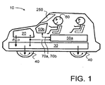
- a road vehicle indicated generally by 10 including an automatic collision avoidance system according to the present invention.
- the vehicle 10 comprises an engine 20 for providing motive power, the engine 20 being coupled via a transmission arrangement 30 to one or more wheels 40 of the vehicle 10.
- the vehicle 10 includes a configuration of sub-systems denoted generally by 50a, 50b coupled to associated data networks 70a, 70b for assisting a driver 60 of the vehicle 10 to operate the vehicle 10.
- the configuration of sub-systems 50a, 50b is illustrated schematically in greater detail in Figure 2 .
- the data networks 70a, 70b are optionally implemented to conform to conventional standards, for example in conformity with the HS-CAN or MS_CAN standard devised by Koninklijke Philips Electronics N.V.
- the HS-CAN standard was originally developed for engine management networks but is increasingly being adopted by motor manufacturers for passenger safety and comfort functions as well as providing a backbone for diverse vehicle functions.
- the aforesaid configuration of sub-systems 50a, 50b comprises a closing velocity (CV) sensor 100 and a driver information module (DIM) 110; the closing velocity (CV) sensor 100 is based on aforementioned IR-laser components.
- the closing velocity (CV) sensor 100 and the module 110 are coupled via the MS_CAN network 70a to a central electronic module (CEM) 120 also forming a part of the configuration of sub-systems 50a, 50b.
- the central electronic module 120 is, in turn, coupled to the HS_CAN network 70b.
- the HS_CAN network 70b is also coupled to a steering angle sensor (SAS) 130, to a brake control module (BCM) 150, to a transmission control module (TCM) 160, to an engine control module (ECM) 170, and to a supplementary restraints system (SRS) 180.
- the sensors 100, 130, the control modules 150, 160, 170, and the restraints system 180 are also included in the aforementioned configuration of sub-systems 50a, 50b.
- a dedicated additional communication network denoted by 190 is included for enabling the closing velocity sensor 100 and the supplementary restraints system 180 to directly mutually communicate.
- This optional additional communication network 190 is capable of providing enhanced reliability of communication between the closing velocity sensor 100 and the supplementary restraints system 180.
- the supplementary restraints system 180 includes a range of operative features such as airbags, one or more brakes and other structures operable to reduce injury to the driver 60 and other occupants in the vehicle 10 in an event of a potential crash of the vehicle 10; the other structures are, for example, elucidated in the aforesaid Table 1.
- the vehicle 10 is operable to move by way of motive power being coupled from the engine 20 via the transmission arrangement 30 to the one or more wheels 40.
- Controls accessible to the driver 60 are actuated by the driver 60 for controlling speed, direction of travel, and braking of the vehicle 10.
- the configuration of sub-systems 50a, 50b is operable to implement aforementioned automatic braking in situations in which the closing velocity sensor 100, in combination with its signal processing software executing on computing hardware, identifies a risk of crash of the vehicle 10.
- the sensor 100 autonomously sends warning messages via the data network 70b to the brake control module 150 so that the vehicle 10 decelerates at a rate of, for example, substantially 3 metres/second/second; prior to the brake control module 150 operating to decelerate the vehicle 10, the configuration of sub-systems 50a, 50b is preferably operable to provide the driver 60 with at least one of an audio warning and a visual warning indicative that the vehicle 10 will be thereafter subject to automatic deceleration.
- the closing velocity (CV) sensor 100 communicates directly via one or more of the additional communication networks to the supplementary restraints system 180, for example, the restraints system 180 may also include a braking function as described in the foregoing.
- the messages sent from the closing velocity (CV) sensor 100 can also trigger deployment of other secondary restraints, for example air bags or similar energy absorbing structures as elucidated in Table 1, for example to cause seatbelt tensioning in preparation for a potential crash. Such seatbelt tensioning is effective at potentially reducing occupant chest injuries in a crash situation.
- the threshold is optionally chosen to be at a relatively slow speed, in comparison to a maximum speed that the vehicle 10 is capable of travelling.
- the rate of deceleration described in the foregoing is chosen to be a compromise between avoiding excessively abrupt automatic braking, and reducing the vehicle's 10 kinetic energy as much as possible so as to try to reduce potential impact damage to the vehicle 10 and injury to the driver 60.
- the additional network 190 is capable of providing one or more additional communications paths, for example by way of redundancy, thereby enhancing communication reliability so that automatic braking is more reliably provided in operation in crash situations.
- the automatic braking function provided in the vehicle 10 is optionally configured for achieving crash avoidance when the vehicle 10 is travelling at speeds of less than 12 km/h, namely substantially less than 3.5 metres/second speed; in such case, the vehicle 10 is brought to a stationary state within substantially 1 second after the closing velocity sensor 100 detects a potential impact.
- the automatic braking function in the vehicle 10 is optionally configured for achieving crash mitigation when the vehicle 10 is travelling at speeds in a range of 12 km/h to 20 km/h; at a speed of 20 km/h, the vehicle 10 is potentially brought to a stationary state within a period of substantially 2 seconds.
- the range of the closing velocity sensor 100 is, for example, only 6 to 8 metres which corresponds to circa 1.5 seconds travel at 20 km/h.
- crash mitigation is possible to achieve in the speed range of 12 km/h to 20 km/h.
- the closing velocity (CV) sensor 100 is optionally mounted at a position in the vehicle 10 whereat it is able to most optimally sense oncoming objects in front of the vehicle 10 and yet be robust to contamination, dirt, condensation, solar radiation and potential damage from stones and other small objects encountered in road environments. Moreover, the closing velocity (CV) sensor 100 is optionally included in the vehicle 10 in a position most suitable for simplifying manufacture. The closing velocity (CV) sensor 100 is most beneficially included in the vehicle as a windscreen electronic module (WEM). A windscreen 250 of the vehicle 10 is therefore optionally arranged to exhibit sufficient infrared transmission at a radiation wavelength of 905 nm substantially at which the closing velocity sensor 100 operates.
- WEM windscreen electronic module
- the closing velocity sensor 100 be included behind the windscreen 250 so that the windscreen 250 provides mechanical and weather protection for the sensor 100 and an environment within the vehicle 10 avoids problems with condensation; such an arrangement is illustrated schematically in Figure 4 whereat the electronic module (WEM) is mounted towards an upper region of the windscreen 250.
- the closing velocity (CV) sensor 100 can also be included in combination with one or more front headlamp units of the vehicle 10, for example protected by their glass front covers; the glass front covers are beneficially operable to be transmissive to radiation having a wavelength corresponding to that of the three beams of infrared radiation generated by the closing velocity sensor 100 when in operation.
- FIG. 3 A crash energy reduction provided by the automatic collision management system pursuant to the present invention described in the foregoing is illustrated in Figure 3 .
- a graph indicated generally by 300 The graph 300 includes an abscissa axis 310 representing speed of the vehicle 10 in km/hour prior to automatic braking pursuant to the present invention being applied.
- the graph 300 includes an ordinate axis 320 representing energy reduction provided to the vehicle by virtue of the aforesaid automatic braking.
- the automatic collision management system included in the vehicle 10 is operable to provide the vehicle 10 with energy reduction as represented by a curve on the graph, the curve being identified by curve sections 330 to 360.
- the automatic collision management system For speeds of the vehicle above 20 km/hour, the automatic collision management system is arranged not to intervene to provide braking; consequently, the curve section 330 then pertains wherein zero energy reduction is provided by the automatic collision management system.
- the automatic collision management system For speeds of the vehicle 10 around the aforesaid threshold speed of 20 km/hour, the automatic collision management system is operational to provide a degree of crash mitigation as represented by a curve section 340.
- the automatic collision management system is capable of decelerating the vehicle 10 to standstill, thereby avoiding impact and hence providing 100% crash energy reduction.
- the automatic collision management system is operable to provide deceleration but unable to bring the vehicle to a complete standstill before the vehicle impacts onto stationary objects, thereby providing a degree of crash mitigation as represented by a curve section 350.
- curve sections 330 to 360 shown in Figure 3 will alter in form if the detection range of the closing velocity (CV) sensor 100 is modified, the deceleration rate of the automatic collision management system is altered, and the aforesaid threshold speed below which automatic braking is implemented is altered.
- a slower rate of deceleration than 3 metres/second/second for example substantially 2 metres/second/second, results in a crash energy reduction characteristic as represented by a curve 360.
- FIG 4 an example of spatial positioning of the closing velocity (CV) sensor 100 within the vehicle 10 is illustrated.
- the closing velocity (CV) sensor 100 is located optionally behind the windscreen 250 at an upper region thereof, although other positions can be adopted if required. More optionally, the closing velocity (CV) sensor 100 is included as part of a windscreen electronic module (WEM) 410.
- the WEM 410 can also include other sensors, for example optical sensors for monitoring headlights of on-coming vehicles so as to provide the vehicle 10 with an automatic headlight-dimming function.
- the closing velocity (CV) sensor 100 is itself synergistically additionally capable of functioning as a precipitation sensor, for example a rain sensor, and as an ambient light sensor.
- the aforementioned threshold speed and/or the aforementioned rate of deceleration in crash avoidance or crash mitigation situations can be modified in response to a precipitation condition detected by the closing velocity (CV) sensor 100, for example to enhance controllability of the vehicle 10 in wet or icy conditions.
- CV closing velocity
- the windscreen 250 is, as described earlier, fabricated from a material which allows three pulsed beams of infrared radiation 400a, 400b, 400c to propagate through the windscreen 250 and be subsequently reflected from oncoming objects in front of the vehicle 10 to generate corresponding reflected radiation which is received back at the closing rate (CV) sensor 100.
- CV closing rate
- the closing velocity (CV) sensor 100 is designed to be optionally mounted at a relatively high position onto or close to the windscreen 250 of the vehicle 10. Such a mounting position potentially provides an optimal field of view of a region in front of the vehicle 10, namely in a region wherein one or more potential impact hazards are likely to be encountered.
- each beam 400a, 400b, 400c also provides a vertical field of sensing of substantially 8° with an inclination of substantially 4° in respect of a horizontal plane.
- Each sensing sector is provided with a set of three corresponding lenses in the sensor 100.
- light sensitive diodes are employed, each in combination with its three lenses, to sense reflection of the beams 400a, 400b, 400c reflected back to the sensor 100.
- the diodes and their respective lenses are beneficially optically shielded from their corresponding lasers employed for generating the beams 400a, 400b, 400c to reduce direct coupling of optical radiation from the lasers to their respective light sensitive diodes.
- the lasers employed within the sensor 100 optionally exhibit an output radiation wavelength of substantially 905 nanometres and are class I laser category with regard to their radiation power output.
- the closing velocity (CV) sensor 100 provides distance and velocity information regarding one or more oncoming objects in front of the vehicle 10 at an update rate of substantially 100 Hz, namely at 10 millisecond intervals.
- a sensing cycle is optionally implemented in the sensor 100 for each of the sectors.
- the cycle commences by each laser in the sensor 100 providing a burst of laser radiation for emission from the sensor 100.
- the burst has a duration of 2 milliseconds and comprises 100 pulses of radiation, wherein each pulse has a duration of substantially 30 nanoseconds.
- the aforesaid light sensitive diodes are scanned for substantially 100 nanoseconds to derive reflected radiation signals.
- the sensor 100 employs time-of-flight (TOF) measurements of IR-laser pulses to calculate relative distances between the vehicle 10 and one or more potentially hazardous objects in front of the vehicle 10; measured distance changes within a well-defined period of time are used to generate relative velocity data and hence aforesaid closing velocity data for the automatic collision management system.
- TOF time-of-flight
- the closing velocity (CV) sensor 100 can also be implemented using optical or radar Doppler techniques, wherein a portion of reflected radiation from one or more oncoming objects in a direction of travel of the vehicle 10 is mixed at the sensor 100 with a portion of radiation emitted from the sensor 100 towards the one or more oncoming objects to generate a Doppler beat signal from which a measure of closing velocity of the one or more objects to the vehicle 10 can be derived.
Landscapes
- Engineering & Computer Science (AREA)
- Mechanical Engineering (AREA)
- Transportation (AREA)
- Automation & Control Theory (AREA)
- Radar, Positioning & Navigation (AREA)
- Remote Sensing (AREA)
- Chemical & Material Sciences (AREA)
- Combustion & Propulsion (AREA)
- Traffic Control Systems (AREA)
- Regulating Braking Force (AREA)
- Control Of Driving Devices And Active Controlling Of Vehicle (AREA)
Claims (27)
- Système de gestion automatique de collision (50a, 50b, 100, 180) pour un véhicule (10), ledit véhicule (10) comprenant des caractéristiques de fonctionnement qui incluent un ou plusieurs freins aptes en fonctionnement à être appliqués à une décélération dudit véhicule (10), ledit système de gestion automatique de collision (50a, 50b, 100, 180) comprenant un dispositif à capteur(s) (100), apte en fonctionnement à détecter des vitesses d'approche d'un ou de plusieurs objets qui se rapprochent sensiblement dans la direction de déplacement du véhicule (10), et un dispositif de traitement (50a, 50b, 100, 180), prévu pour recevoir en provenance du dispositif à capteur(s) (100) des informations fournissant des indications relatives auxdites vitesses d'approche détectées, ledit dispositif de traitement (50a, 50b, 100, 180) étant, lorsque le véhicule (10) se déplace au-dessous d'une vitesse de seuil, apte en fonctionnement à appliquer automatiquement et de manière sélective lesdites caractéristiques de fonctionnement, incluant ledit ou lesdits freins, à la décélération du véhicule (10) en réponse auxdites informations reçues du dispositif à capteur(s) (100) afin d'éviter ou d'atténuer une collision du véhicule (10) dans ledit ou lesdits objets qui se rapprochent, le système de gestion de collision étant non actif pour procurer un freinage automatique à la vitesse de seuil ou au-dessus de celle-ci, caractérisé en ce que ledit dispositif à capteur(s) (100) a une plage de détection d'une distance de 6 à 8 mètres par rapport au véhicule (10), le dispositif à capteur(s) (100) étant, dans cette plage de détection, apte en fonctionnement à détecter ledit ou lesdits objets qui se rapprochent.
- Système de gestion automatique de collision (50a, 50b, 100, 180) tel que revendiqué dans la revendication 1, dans lequel la vitesse de seuil est située dans une plage comprise entre 10 km/heure et 30 km/heure.
- Système de gestion automatique de collision (50a, 50b, 100, 180) tel que revendiqué dans la revendication 2, dans lequel la vitesse de seuil est sensiblement égale à 20 km/heure.
- Système de gestion automatique de collision (50a, 50b, 100, 180) tel que revendiqué dans l'une quelconque des revendications précédentes, dans lequel le dispositif de traitement (50a, 50b, 100, 180) est apte en fonctionnement à permettre que le ou les freins du véhicule (10) provoque(nt) une décélération du véhicule (10) d'une valeur située dans une plage comprise entre 1 mètre/seconde par seconde et 5 mètres/seconde par seconde.
- Système de gestion automatique de collision (50a, 50b, 100, 180) tel que revendiqué dans la revendication 4, dans lequel le dispositif de traitement (50a, 50b, 100, 180) est apte en fonctionnement à permettre que le ou les freins du véhicule (10) provoque(nt) une décélération du véhicule (10) d'une valeur sensiblement égale à 3 mètres/seconde par seconde.
- Système de gestion automatique de collision (50a, 50b, 100, 180) tel que revendiqué dans l'une quelconque des revendications 1 à 5, dans lequel le dispositif à capteur(s) (100) comprend un détecteur de vitesse d'approche apte en fonctionnement à utiliser un ou plusieurs capteurs à laser infrarouge pour détecter le ou les objets qui se rapprochent.
- Système de gestion automatique de collision (50a, 50b, 100, 180) tel que revendiqué dans la revendication 6, dans lequel ledit ou lesdits capteurs à laser infrarouge (100) sont aptes en fonctionnement à utiliser une analyse de décalage de fréquence optique d'écho d'impulsion et/ou de type Doppler pour détecter ledit ou lesdits objets qui se rapprochent.
- Système de gestion automatique de collision (50a, 50b, 100, 180) tel que revendiqué dans l'une quelconque des revendications 1 à 7, dans lequel le dispositif à capteur(s) (100) est prévu pour être monté à l'arrière d'un pare-brise (250) du véhicule (10) au travers duquel un conducteur (60) du véhicule (10) observe une région située en face du véhicule (10), le dispositif à capteur(s) (100) étant apte en fonctionnement à détecter à travers le pare-brise (250) le ou les objets qui se rapprochent.
- Système de gestion automatique de collision (50a, 50b, 100, 180) tel que revendiqué dans la revendication 8, dans lequel ledit dispositif à capteur(s) (100) est prévu pour être monté au niveau de la partie supérieure du pare-brise (250).
- Système de gestion automatique de collision (50a, 50b, 100, 180) tel que revendiqué dans l'une quelconque des revendications 1 à 7, dans lequel ledit véhicule (10) comprend un module électronique (410) de pare-brise, et ledit dispositif à capteur(s) (100) est inclus dans ledit module électronique (410) de pare-brise.
- Système de gestion automatique de collision (50a, 50b, 100, 180) tel que revendiqué dans la revendication 10, dans lequel le module électronique (410) de pare-brise forme une seule unité avec un pare-brise (250) du véhicule (10).
- Système de gestion automatique de collision (50a, 50b, 100, 180) tel que revendiqué dans la revendication 10, dans lequel le module électronique (410) de pare-brise incorpore d'autres détecteurs en plus du dispositif à capteur(s) (100).
- Système de gestion automatique de collision (50a, 50b, 100, 180) tel que revendiqué dans l'une quelconque des revendications précédentes, dans lequel le dispositif à capteur(s) (100), le dispositif de traitement (50a, 50b, 100, 180) et le ou les freins sont couplés de manière à être en communication réciproque par l'intermédiaire d'un ou de plusieurs réseaux de communication de données (70a, 70b) du véhicule (10).
- Système de gestion automatique de collision (50a, 50b, 100, 180) tel que revendiqué dans la revendication 13, dans lequel le ou les réseaux de communication de données (70a, 70b) sont constitués par un ou plusieurs des réseaux : HS_CAN, MS_CAN, CAN, LIN.
- Système de gestion automatique de collision (50a, 50b, 100, 180) tel que revendiqué dans l'une quelconque des revendications précédentes, dans lequel le dispositif à capteur(s) (100), le dispositif de traitement (50a, 50b, 100, 180) et le ou les freins sont couplés de manière réciproque par l'intermédiaire d'une pluralité de trajets de réseau de communication parallèles (70a, 70b, 180) en vue d'améliorer la fiabilité de freinage afin d'atténuer ou d'éviter un impact avec ledit ou lesdits objets qui se rapprochent.
- Système de gestion automatique de collision (50a, 50b, 100, 180) tel que revendiqué dans l'une quelconque des revendications précédentes, dans lequel le système (50a, 50b, 100, 180) est, afin d'éviter ou d'atténuer une collision du véhicule (10), apte en fonctionnement à mettre en oeuvre d'autres mesures de fonctionnement qui s'ajoutent à ladite application automatique et sélective dudit ou desdits freins, lesdites autres mesures de fonctionnement comprenant au moins l'une des suivantes :un ajustement adaptatif de la direction du véhicule, un découplage des pédales du conducteur, un réglage adaptatif des ceintures de sécurité, le déploiement d'airbags, un avertissement sonore, un avertissement visuel.
- Système de gestion automatique de collision (50a, 50b, 100, 180) tel que revendiqué dans la revendication 16, dans lequel le dispositif de traitement (100) est apte en fonctionnement à activer l'avertissement sonore et/ou l'avertissement visuel avant que ledit ou lesdits freins ne soient appliqués à la décélération du véhicule (10).
- Système de gestion automatique de collision (50a, 50b, 100, 180) tel que revendiqué dans la revendication 16, dans lequel ledit réglage adaptatif des ceintures de sécurité est apte en fonctionnement à tendre une ou plusieurs des ceintures de sécurité du véhicule, en combinaison avec l'application dudit ou desdits freins à la décélération du véhicule.
- Système de gestion automatique de collision (50a, 50b, 100, 180) tel que revendiqué dans l'une quelconque des revendications précédentes, dans lequel le dispositif à capteur(s) (100) est également apte en fonctionnement à détecter une précipitation extérieure au véhicule (10), et le dispositif de traitement est apte en fonctionnement à modifier la vitesse de seuil et/ou la décélération du véhicule (10) en réponse à la précipitation extérieure au véhicule (10) qui a été détectée.
- Procédé de mise en oeuvre d'un freinage automatique dans un véhicule (10), ledit véhicule (10) incorporant un système de gestion automatique de collision (50a, 50b, 100, 180) qui comprend un dispositif à capteur(s) (100), couplé pour établir une communication avec un dispositif de traitement (50a, 50b, 100, 180), et un ou plusieurs freins du véhicule (10), ledit procédé comprenant les étapes qui consistent à :(a) mettre en oeuvre le dispositif à capteur(s) (100) pour détecter des vitesses d'approche d'un ou de plusieurs objets qui se rapprochent dans une plage de détection de distances comprise entre 6 et 8 mètres par rapport au véhicule (10) dans la direction de déplacement du véhicule (10) ;(b) recevoir au niveau du dispositif de traitement (50a, 50b, 100, 180), en provenance du dispositif à capteur(s) (100), des informations décrivant lesdites vitesses d'approche dudit ou desdits objets qui se rapprochent, et, à partir desdites informations, évaluer si une collision entre ledit ou lesdits objets qui se rapprochent et le véhicule (10) est probable ou non, et(c) déclencher l'application automatique dudit ou desdits freins du véhicule (10) lorsque le dispositif de traitement a déterminé qu'un risque de collision était probable, ledit freinage automatique étant appliqué seulement si le véhicule (10) se déplace, en fonctionnement, à une vitesse qui est inférieure à une vitesse de seuil.
- Procédé tel que revendiqué dans la revendication 20, dans lequel la vitesse de seuil est située dans une plage comprise entre 10 km/heure et 30 km/heure.
- Procédé tel que revendiqué dans la revendication 21, dans lequel la vitesse de seuil est sensiblement égale à 20 km/heure.
- Procédé tel que revendiqué dans l'une quelconque des revendications 20 à 22, dans lequel le dispositif de traitement (50a, 50b, 100, 180) est apte en fonctionnement à provoquer une décélération du véhicule (10) d'une valeur située dans une plage comprise entre 1 mètre/seconde par seconde et 5 mètres/seconde par seconde dans le cas où un ou plusieurs objets qui se rapprochent sont détectés.
- Procédé tel que revendiqué dans la revendication 23, dans lequel le dispositif de traitement (50a, 50b, 100, 180) est apte en fonctionnement à provoquer une décélération du véhicule (10) d'une valeur sensiblement égale à 3 mètres/seconde par seconde dans le cas où un ou plusieurs objets qui se rapprochent sont détectés.
- Procédé tel que revendiqué dans la revendication 20, comprenant une étape qui consiste à prévoir que le dispositif à capteur(s) (100) génère une pluralité de faisceaux infrarouges (400a, 400b, 400c) de rayonnement optique afin de détecter ledit ou lesdits objets qui se rapprochent.
- Procédé tel que revendiqué dans la revendication 25, comprenant en outre une étape qui consiste à diriger les faisceaux infrarouges (400a, 400b, 400c) de rayonnement optique au travers d'un pare-brise (250) dudit véhicule (10) afin de détecter ledit ou lesdits objets qui se rapprochent.
- Procédé tel que revendiqué dans la revendication 20, dans lequel le dispositif à capteur(s) (100) est en outre apte en fonctionnement à détecter une précipitation extérieure au véhicule (10), et le dispositif de traitement est apte en fonctionnement à modifier la vitesse de seuil et/ou la décélération du véhicule (10) en réponse à la détection d'une précipitation extérieure au véhicule (10).
Priority Applications (1)
| Application Number | Priority Date | Filing Date | Title |
|---|---|---|---|
| EP08152678.2A EP1944187B1 (fr) | 2005-08-04 | 2005-08-04 | Système automatique de gestion des collisions |
Applications Claiming Priority (2)
| Application Number | Priority Date | Filing Date | Title |
|---|---|---|---|
| EP05016943A EP1749687B1 (fr) | 2005-08-04 | 2005-08-04 | Système de gestion de collision automatique |
| EP08152678.2A EP1944187B1 (fr) | 2005-08-04 | 2005-08-04 | Système automatique de gestion des collisions |
Related Parent Applications (2)
| Application Number | Title | Priority Date | Filing Date |
|---|---|---|---|
| EP05016943.2 Division | 2005-08-04 | ||
| EP05016943A Division EP1749687B1 (fr) | 2005-08-04 | 2005-08-04 | Système de gestion de collision automatique |
Publications (3)
| Publication Number | Publication Date |
|---|---|
| EP1944187A2 EP1944187A2 (fr) | 2008-07-16 |
| EP1944187A3 EP1944187A3 (fr) | 2009-09-09 |
| EP1944187B1 true EP1944187B1 (fr) | 2013-11-13 |
Family
ID=35385459
Family Applications (5)
| Application Number | Title | Priority Date | Filing Date |
|---|---|---|---|
| EP08152678.2A Active EP1944187B1 (fr) | 2005-08-04 | 2005-08-04 | Système automatique de gestion des collisions |
| EP08152682A Ceased EP1944188A3 (fr) | 2005-08-04 | 2005-08-04 | Système automatique de gestion des collisions |
| EP05016943A Active EP1749687B1 (fr) | 2005-08-04 | 2005-08-04 | Système de gestion de collision automatique |
| EP08152680.8A Active EP1942026B1 (fr) | 2005-08-04 | 2005-08-04 | Système automatique de gestion des collisions |
| EP08152683.2A Active EP1944189B2 (fr) | 2005-08-04 | 2005-08-04 | Système automatique de gestion des collisions |
Family Applications After (4)
| Application Number | Title | Priority Date | Filing Date |
|---|---|---|---|
| EP08152682A Ceased EP1944188A3 (fr) | 2005-08-04 | 2005-08-04 | Système automatique de gestion des collisions |
| EP05016943A Active EP1749687B1 (fr) | 2005-08-04 | 2005-08-04 | Système de gestion de collision automatique |
| EP08152680.8A Active EP1942026B1 (fr) | 2005-08-04 | 2005-08-04 | Système automatique de gestion des collisions |
| EP08152683.2A Active EP1944189B2 (fr) | 2005-08-04 | 2005-08-04 | Système automatique de gestion des collisions |
Country Status (3)
| Country | Link |
|---|---|
| US (1) | US20070032952A1 (fr) |
| EP (5) | EP1944187B1 (fr) |
| DE (1) | DE602005006269T2 (fr) |
Families Citing this family (46)
| Publication number | Priority date | Publication date | Assignee | Title |
|---|---|---|---|---|
| US7937075B2 (en) * | 2006-10-06 | 2011-05-03 | At&T Intellectual Property I, L.P. | Mode changing of a mobile communications device and vehicle settings when the mobile communications device is in proximity to a vehicle |
| EP2045143B1 (fr) * | 2007-10-02 | 2016-07-27 | Volvo Car Corporation | Procédé et agencement de limitation de charge d'une ceinture de sécurité |
| US8335615B2 (en) * | 2008-06-13 | 2012-12-18 | Ford Global Technologies, Llc | Whiplash reduction system |
| TWI393644B (zh) * | 2008-12-04 | 2013-04-21 | Inst Information Industry | 行車碰撞管理系統及方法,及其電腦程式產品 |
| US9475464B2 (en) * | 2009-07-09 | 2016-10-25 | Ford Global Technologies, Llc | Sensor system and method for a vehicle |
| WO2011038764A1 (fr) * | 2009-09-30 | 2011-04-07 | Jentschura, Rolf | Système de contrôle de la position de pièces de véhicules |
| CN102248945B (zh) * | 2010-05-21 | 2014-10-29 | 上海理工大学 | 激光扫描式车辆主动避撞系统 |
| DE102010033008A1 (de) | 2010-07-31 | 2011-03-17 | Daimler Ag | Verfahren zum Betreiben eines Kollisionsvermeidungssystems eines Fahrzeugs |
| GB2488154A (en) * | 2011-02-18 | 2012-08-22 | Jaguar Cars | Target object determination for vehicle braking system |
| US8694222B2 (en) * | 2011-10-26 | 2014-04-08 | GM Global Technology Operations LLC | Collision avoidance system and method of operating the same |
| FR2987018B1 (fr) * | 2012-02-16 | 2014-03-28 | Peugeot Citroen Automobiles Sa | Procede de freinage automatique pour vehicule automobile. |
| WO2013126582A1 (fr) * | 2012-02-21 | 2013-08-29 | Elwha Llc | Systèmes et procédés pour une assurance basée sur des caractéristiques surveillées d'un système de détection de collision |
| US8595037B1 (en) | 2012-05-08 | 2013-11-26 | Elwha Llc | Systems and methods for insurance based on monitored characteristics of an autonomous drive mode selection system |
| US9000903B2 (en) | 2012-07-09 | 2015-04-07 | Elwha Llc | Systems and methods for vehicle monitoring |
| US9558667B2 (en) | 2012-07-09 | 2017-01-31 | Elwha Llc | Systems and methods for cooperative collision detection |
| US9165469B2 (en) | 2012-07-09 | 2015-10-20 | Elwha Llc | Systems and methods for coordinating sensor operation for collision detection |
| EP2934967B1 (fr) | 2012-12-20 | 2019-01-02 | Continental Teves AG & Co. OHG | Procédé et dispositif de freinage et de commande de direction automatisés d'un véhicule |
| JP5835242B2 (ja) * | 2013-02-01 | 2015-12-24 | 株式会社デンソー | 車両用安全制御システム |
| US20140257627A1 (en) * | 2013-03-11 | 2014-09-11 | Ford Global Technologies, Llc | Potential chassis damage identification and notification system |
| DE102013214383A1 (de) * | 2013-07-23 | 2015-01-29 | Robert Bosch Gmbh | Verfahren und Vorrichtung zum Bereitstellen eines Kollisionsignals hinsichtlich einer Fahrzeugkollision, Verfahren und Vorrichtung zum Verwalten von Kollisionsdaten hinsichtlich Fahrzeugkollisionen sowie Verfahren und Vorrichtung zum Steuern zumindest einer Kollisionsschutzeinrichtung eines Fahrzeugs |
| US20150066346A1 (en) * | 2013-08-28 | 2015-03-05 | Elwha LLC, a limited liability company of the State of Delaware | Vehicle collision management system responsive to a situation of an occupant of an approaching vehicle |
| US20150066345A1 (en) * | 2013-08-28 | 2015-03-05 | Elwha Llc | Vehicle collision management system responsive to user-selected preferences |
| US9472104B2 (en) | 2013-11-26 | 2016-10-18 | Elwha Llc | Systems and methods for automatically documenting an accident |
| DE102014207964A1 (de) * | 2014-04-28 | 2015-10-29 | Zf Friedrichshafen Ag | Vermeidung von Kollisionen mit fallenden Objekten |
| KR101628503B1 (ko) * | 2014-10-27 | 2016-06-08 | 현대자동차주식회사 | 운전자 보조장치 및 그 작동 방법 |
| US9855890B2 (en) * | 2014-12-11 | 2018-01-02 | Toyota Motor Engineering & Manufacturing North America, Inc. | Autonomous vehicle interaction with external environment |
| JP2016124389A (ja) * | 2014-12-26 | 2016-07-11 | トヨタ自動車株式会社 | 車両制動制御装置 |
| US10290159B2 (en) | 2016-02-11 | 2019-05-14 | Ford Global Technologies, Llc | Potential chassis damage identification, validation, and notification |
| DE102016209556A1 (de) * | 2016-06-01 | 2017-12-07 | Robert Bosch Gmbh | Verfahren zum Bereitstellen einer Information bezüglich eines Fußgängers in einem Umfeld eines Fahrzeugs und Verfahren zum Steuern eines Fahrzeugs |
| CN108202740B (zh) * | 2016-12-16 | 2021-06-22 | 奥迪股份公司 | 防碰撞辅助系统和方法 |
| CN106515578A (zh) * | 2016-12-22 | 2017-03-22 | 百度在线网络技术(北京)有限公司 | 无人车驾驶状态的识别装置、识别方法及无人车 |
| KR101996417B1 (ko) * | 2016-12-30 | 2019-07-04 | 현대자동차주식회사 | 자세 정보 기반 보행자 탐지 및 보행자 충돌 방지 장치 및 방법 |
| KR101996416B1 (ko) * | 2016-12-30 | 2019-10-01 | 현대자동차주식회사 | 보행자 충돌 시 충격 완화 장치 및 방법 |
| KR101996420B1 (ko) * | 2016-12-30 | 2019-10-01 | 현대자동차주식회사 | 보행자 충돌 시 충격 완화 장치 및 방법 |
| KR101996414B1 (ko) * | 2016-12-30 | 2019-07-04 | 현대자동차주식회사 | 보행자 시선을 고려한 충돌 방지 및 충격 완화 장치 및 방법 |
| US20180217245A1 (en) * | 2017-01-30 | 2018-08-02 | GM Global Technology Operations LLC | Detecting abrupt deceleration using doppler effect of signal change |
| US10183641B2 (en) * | 2017-03-23 | 2019-01-22 | Baidu Usa Llc | Collision prediction and forward airbag deployment system for autonomous driving vehicles |
| KR102616561B1 (ko) * | 2018-12-18 | 2023-12-21 | 모셔널 에이디 엘엘씨 | 복수의 모션 제약을 사용하는 차량의 동작 |
| US11899464B2 (en) | 2018-12-18 | 2024-02-13 | Motional Ad Llc | Operation of a vehicle using motion planning with machine learning |
| KR102641417B1 (ko) * | 2019-02-20 | 2024-02-27 | 현대모비스 주식회사 | 보행자 보호 장치 및 방법 |
| US11299178B1 (en) | 2019-03-01 | 2022-04-12 | Nissan Motor Co., Ltd. | Vehicle travel control method and vehicle travel control device |
| US11358593B2 (en) | 2019-07-09 | 2022-06-14 | King Fahd University Of Petroleum And Minerals | Dual direction accident prevention and assistive braking system |
| US20220390560A1 (en) * | 2019-11-05 | 2022-12-08 | Outsight | Adaptive Active Safety System using Multi-spectral LIDAR, and Method implemented in the Adaptive Active Safety System |
| US11479073B2 (en) * | 2020-03-05 | 2022-10-25 | GM Global Technology Operations LLC | Vehicle body roll reduction |
| JP7068365B2 (ja) * | 2020-03-05 | 2022-05-16 | 本田技研工業株式会社 | 車両制御装置、車両及び車両制御方法 |
| US11505180B2 (en) * | 2020-06-30 | 2022-11-22 | Rivian Ip Holdings, Llc | Active energy management for frontal impacts |
Citations (2)
| Publication number | Priority date | Publication date | Assignee | Title |
|---|---|---|---|---|
| DE10231687A1 (de) * | 2002-07-10 | 2004-01-22 | Robert Bosch Gmbh | Verfahren und Vorrichtung zur Benachtichtigung des Fahrers eines Kraftfahrzeugs |
| WO2008043852A1 (fr) * | 2006-10-13 | 2008-04-17 | Continental Teves Ag & Co. Ohg | Système de détermination d'objets |
Family Cites Families (50)
| Publication number | Priority date | Publication date | Assignee | Title |
|---|---|---|---|---|
| US3898652A (en) | 1973-12-26 | 1975-08-05 | Rashid Mary D | Vehicle safety and protection system |
| DE3637165A1 (de) * | 1986-10-31 | 1988-05-05 | Rainer Ashauer | Verfahren und einrichtung zum verhindern von zusammenstoessen, insbesondere fuer kraftfahrzeuge im strassenverkehr |
| JP2722746B2 (ja) * | 1990-01-29 | 1998-03-09 | 日産自動車株式会社 | 自動ブレーキ装置 |
| DE4020833C2 (de) * | 1990-06-29 | 1994-11-24 | Deutsche Aerospace | Lasersensor |
| US5314037A (en) * | 1993-01-22 | 1994-05-24 | Shaw David C H | Automobile collision avoidance system |
| US5529138A (en) * | 1993-01-22 | 1996-06-25 | Shaw; David C. H. | Vehicle collision avoidance system |
| US6405132B1 (en) * | 1997-10-22 | 2002-06-11 | Intelligent Technologies International, Inc. | Accident avoidance system |
| DE19534942C1 (de) * | 1995-09-20 | 1998-05-28 | Siemens Ag | Verfahren zur Kollisionsvermeidung von einem entgegenkommenden Fahrzeug und einem ausweichenden Fahrzeug mit Hilfe neuronaler Netze |
| JPH09188133A (ja) * | 1996-01-12 | 1997-07-22 | Takata Kk | ウィンドシールド及びセンサ設置構造 |
| GB9602250D0 (en) * | 1996-02-05 | 1996-04-03 | Secr Defence | Collision warning system |
| JP3726923B2 (ja) * | 1996-04-10 | 2005-12-14 | 富士重工業株式会社 | 車両用運転支援装置 |
| DE19634567B4 (de) * | 1996-08-27 | 2007-11-29 | Robert Bosch Gmbh | Elektrisches Bremssystem |
| DE19647430C2 (de) * | 1996-11-15 | 2001-04-26 | Annett Runnwerth | Verfahren und Vorrichtung zum selbsttätigen Bremsen eines personengeführten Kraftfahrzeuges |
| JP3927265B2 (ja) * | 1996-11-18 | 2007-06-06 | トヨタ自動車株式会社 | 車両の自動制動制御装置 |
| US6014601A (en) * | 1997-01-07 | 2000-01-11 | J. Martin Gustafson | Driver alert system |
| DE19717399C2 (de) † | 1997-04-24 | 2001-05-23 | Martin Spies | Einrichtung zur Bestimmung von Abstand und Art von Objekten sowie der Sichtweite |
| DE19738690C2 (de) * | 1997-09-04 | 2002-05-29 | Bosch Gmbh Robert | Verfahren und Vorrichtung zur Steuerung der Bremsanlage eines Fahrzeugs |
| DE19822535B4 (de) † | 1997-10-29 | 2010-08-05 | Continental Teves Ag & Co. Ohg | Vorrichtung und Verfahren zur Steuerung einer Bremsanlage |
| US6388580B1 (en) * | 1998-07-23 | 2002-05-14 | Rudolph Graham | Automobile unsafe following distance warning system |
| JP3819613B2 (ja) | 1998-10-15 | 2006-09-13 | 本田技研工業株式会社 | 車両の走行安全装置 |
| DE19856313A1 (de) * | 1998-12-07 | 2000-06-08 | Volkswagen Ag | Verfahren zur Überwachung von mehrkanaligen Abstandsmeßsystemen für Fahrzeuge |
| DE19900314C2 (de) * | 1999-01-07 | 2000-10-19 | Daimler Chrysler Ag | Verfahren und Vorrichtung zur Abbremsung eines Kraftfahrzeugs im Nahbereich mit einem Hindernis |
| DE19915253A1 (de) * | 1999-04-03 | 2000-10-05 | Bosch Gmbh Robert | Verfahren und Vorrichtung zum Betreiben eines verteilten Steuersystems in einem Fahrzeug |
| SE9902839D0 (sv) * | 1999-08-05 | 1999-08-05 | Evert Palmquist | Kollisionsskydd för fordon |
| DE19958520A1 (de) * | 1999-12-04 | 2001-06-07 | Bosch Gmbh Robert | Geschwindigkeitsregler für ein Kraftfahrzeug |
| US6278924B1 (en) | 2000-04-19 | 2001-08-21 | Breed Automotive Technology, Inc. | Method of determining safety system deployment with crash velocity input |
| EP1297445A4 (fr) * | 2000-06-09 | 2005-11-23 | Automotive Systems Lab | Processeur de sensibilisation a une situation |
| DE10037826A1 (de) * | 2000-08-03 | 2002-02-14 | Daimler Chrysler Ag | Verfahren und Einrichtung zur selbsttätigen Geschwindigkeitseinstellung in einem Fahrzeug |
| US6530450B2 (en) * | 2000-08-09 | 2003-03-11 | Deluca Michael | Fault reactive securely stopped vehicle method and apparatus |
| US6945346B2 (en) † | 2000-09-28 | 2005-09-20 | Automotive Distance Control Systems Gmbh | Method for operating a driver support system for motor vehicles |
| EP1349131B1 (fr) * | 2000-11-24 | 2006-01-18 | Aisin Seiki Kabushiki Kaisha | Appareil de prevention des collisions entre vehicules |
| DE10063062A1 (de) * | 2000-12-18 | 2002-06-20 | Lucas Varity Gmbh | Verfahren und Vorrichtung zum Steuern einer Bremsausrüstung eines Kraftfahrzeuges |
| JP3800007B2 (ja) * | 2001-01-09 | 2006-07-19 | 日産自動車株式会社 | 制動制御装置 |
| US20020112912A1 (en) * | 2001-02-21 | 2002-08-22 | Napier Steven Lee | System and method for activating a brake system for an automotive vehicle |
| ES2269748T3 (es) * | 2001-07-11 | 2007-04-01 | Robert Bosch Gmbh | Procedimiento y mecanismo de activacion automatica de frenada de un vehiculo. |
| US6655749B2 (en) * | 2001-11-08 | 2003-12-02 | Ford Global Technologies, Llc | Accelerator actuated emergency braking system |
| US6517172B1 (en) * | 2001-11-08 | 2003-02-11 | Ford Global Technologies, Inc. | Driver augmented autonomous braking system |
| DE10157377B4 (de) † | 2001-11-22 | 2005-10-06 | Daimlerchrysler Ag | Fahrzeugdatenbussystem mit Sensormodul |
| US6590495B1 (en) * | 2001-12-11 | 2003-07-08 | Iraj Behbehani | Automobile distance warning and alarm system |
| DE10161233A1 (de) † | 2001-12-13 | 2003-06-26 | Conti Temic Microelectronic | Sensoranordnung zur Abstands-oder Geschwindigkeitsmessung |
| JP3896852B2 (ja) * | 2002-01-16 | 2007-03-22 | 株式会社デンソー | 車両用衝突被害軽減装置 |
| US6480144B1 (en) * | 2002-01-30 | 2002-11-12 | Ford Global Technologies, Inc. | Wireless communication between countermeasure devices |
| US6813562B2 (en) * | 2002-10-15 | 2004-11-02 | General Motors Corporation | Threat assessment algorithm for forward collision warning |
| JP4026477B2 (ja) * | 2002-11-12 | 2007-12-26 | 日産自動車株式会社 | 車両用報知装置 |
| DE10331074A1 (de) † | 2003-07-09 | 2005-02-03 | Conti Temic Microelectronic Gmbh | Sensoranordnung zur Abstands- und/oder Geschwindigkeitsmessung |
| US7027920B2 (en) † | 2003-07-18 | 2006-04-11 | Visteon Global Technologies, Inc. | Low-speed collision avoidance system |
| JP2005049281A (ja) * | 2003-07-30 | 2005-02-24 | Denso Corp | 物体認識装置、及び物体認識方法 |
| DE10340901A1 (de) * | 2003-09-02 | 2005-03-24 | Valeo Schalter Und Sensoren Gmbh | Dachmodul für ein Kraftfahrzeug |
| US7349783B2 (en) * | 2005-06-09 | 2008-03-25 | Delphi Technologies, Inc. | Supplemental restraint deployment method with anticipatory crash classification |
| US7859432B2 (en) * | 2007-05-23 | 2010-12-28 | Che Il Electric Wireing Devices Co., Ltd. | Collision avoidance system based on detection of obstacles in blind spots of vehicle |
-
2005
- 2005-08-04 EP EP08152678.2A patent/EP1944187B1/fr active Active
- 2005-08-04 EP EP08152682A patent/EP1944188A3/fr not_active Ceased
- 2005-08-04 EP EP05016943A patent/EP1749687B1/fr active Active
- 2005-08-04 EP EP08152680.8A patent/EP1942026B1/fr active Active
- 2005-08-04 EP EP08152683.2A patent/EP1944189B2/fr active Active
- 2005-08-04 DE DE602005006269T patent/DE602005006269T2/de active Active
-
2006
- 2006-07-27 US US11/460,378 patent/US20070032952A1/en not_active Abandoned
Patent Citations (2)
| Publication number | Priority date | Publication date | Assignee | Title |
|---|---|---|---|---|
| DE10231687A1 (de) * | 2002-07-10 | 2004-01-22 | Robert Bosch Gmbh | Verfahren und Vorrichtung zur Benachtichtigung des Fahrers eines Kraftfahrzeugs |
| WO2008043852A1 (fr) * | 2006-10-13 | 2008-04-17 | Continental Teves Ag & Co. Ohg | Système de détermination d'objets |
Also Published As
| Publication number | Publication date |
|---|---|
| EP1944188A3 (fr) | 2009-09-09 |
| EP1944187A2 (fr) | 2008-07-16 |
| DE602005006269D1 (fr) | 2008-06-05 |
| EP1944189A2 (fr) | 2008-07-16 |
| EP1944187A3 (fr) | 2009-09-09 |
| EP1942026A3 (fr) | 2009-08-12 |
| EP1944189B1 (fr) | 2013-10-02 |
| DE602005006269T2 (de) | 2009-05-07 |
| EP1942026B1 (fr) | 2013-07-03 |
| EP1749687B1 (fr) | 2008-04-23 |
| US20070032952A1 (en) | 2007-02-08 |
| EP1944189B2 (fr) | 2020-06-03 |
| EP1749687A1 (fr) | 2007-02-07 |
| EP1944188A2 (fr) | 2008-07-16 |
| EP1944189A3 (fr) | 2009-09-09 |
| EP1942026A2 (fr) | 2008-07-09 |
Similar Documents
| Publication | Publication Date | Title |
|---|---|---|
| EP1944187B1 (fr) | Système automatique de gestion des collisions | |
| US10023020B2 (en) | Look ahead vehicle suspension system | |
| US8335615B2 (en) | Whiplash reduction system | |
| US7138938B1 (en) | System and method for preemptively sensing an object and selectively operating both a collision countermeasure system and a parking assistance system aboard an automotive vehicle | |
| US6037860A (en) | Method and arrangement for avoiding and/or minimizing vehicle collisions in road traffic | |
| US20060091654A1 (en) | Sensor system with radar sensor and vision sensor | |
| JP2021147042A (ja) | 重み付きアクティブ−パッシブ衝突モード分類を実行する車両安全システムおよび方法 | |
| JP2021142975A (ja) | 一体型アクティブ−パッシブ正面衝撃制御アルゴリズムを実行する車両安全システム | |
| EP2045143B1 (fr) | Procédé et agencement de limitation de charge d'une ceinture de sécurité | |
| US8738319B2 (en) | System and method for detecting a turning vehicle | |
| JPH06119599A (ja) | 車両走行制御装置 | |
| CN104875730B (zh) | 车辆自动刹车装置及其方法 | |
| JPH06144154A (ja) | 衝撃緩和装置 | |
| KR101596995B1 (ko) | 차량의 충격완화 방법 | |
| JP2012101722A (ja) | 車両の衝突被害軽減装置 |
Legal Events
| Date | Code | Title | Description |
|---|---|---|---|
| PUAI | Public reference made under article 153(3) epc to a published international application that has entered the european phase |
Free format text: ORIGINAL CODE: 0009012 |
|
| AC | Divisional application: reference to earlier application |
Ref document number: 1749687 Country of ref document: EP Kind code of ref document: P |
|
| AK | Designated contracting states |
Kind code of ref document: A2 Designated state(s): DE GB SE |
|
| RIN1 | Information on inventor provided before grant (corrected) |
Inventor name: EDVARDSSON, MIKAEL Inventor name: CARLSTEDT, HANS Inventor name: BROBERG, THOMAS Inventor name: ANDERSSON, TOMAS Inventor name: LOEFVING, BJOERN Inventor name: EKMARK, JONAS |
|
| RIC1 | Information provided on ipc code assigned before grant |
Ipc: B60K 31/00 20060101AFI20080529BHEP Ipc: B60R 21/01 20060101ALN20090430BHEP Ipc: B60R 21/00 20060101ALI20090430BHEP Ipc: B60R 21/013 20060101ALI20090430BHEP |
|
| PUAL | Search report despatched |
Free format text: ORIGINAL CODE: 0009013 |
|
| AK | Designated contracting states |
Kind code of ref document: A3 Designated state(s): DE GB SE |
|
| 17P | Request for examination filed |
Effective date: 20100125 |
|
| 17Q | First examination report despatched |
Effective date: 20100215 |
|
| AKX | Designation fees paid |
Designated state(s): DE GB SE |
|
| RAP1 | Party data changed (applicant data changed or rights of an application transferred) |
Owner name: VOLVO CAR CORPORATION |
|
| GRAP | Despatch of communication of intention to grant a patent |
Free format text: ORIGINAL CODE: EPIDOSNIGR1 |
|
| GRAP | Despatch of communication of intention to grant a patent |
Free format text: ORIGINAL CODE: EPIDOSNIGR1 |
|
| GRAS | Grant fee paid |
Free format text: ORIGINAL CODE: EPIDOSNIGR3 |
|
| GRAP | Despatch of communication of intention to grant a patent |
Free format text: ORIGINAL CODE: EPIDOSNIGR1 |
|
| INTG | Intention to grant announced |
Effective date: 20130612 |
|
| GRAA | (expected) grant |
Free format text: ORIGINAL CODE: 0009210 |
|
| AC | Divisional application: reference to earlier application |
Ref document number: 1749687 Country of ref document: EP Kind code of ref document: P |
|
| AK | Designated contracting states |
Kind code of ref document: B1 Designated state(s): DE GB SE |
|
| REG | Reference to a national code |
Ref country code: GB Ref legal event code: FG4D |
|
| REG | Reference to a national code |
Ref country code: DE Ref legal event code: R096 Ref document number: 602005041870 Country of ref document: DE Effective date: 20140109 |
|
| REG | Reference to a national code |
Ref country code: SE Ref legal event code: TRGR |
|
| REG | Reference to a national code |
Ref country code: DE Ref legal event code: R097 Ref document number: 602005041870 Country of ref document: DE |
|
| PLBE | No opposition filed within time limit |
Free format text: ORIGINAL CODE: 0009261 |
|
| STAA | Information on the status of an ep patent application or granted ep patent |
Free format text: STATUS: NO OPPOSITION FILED WITHIN TIME LIMIT |
|
| 26N | No opposition filed |
Effective date: 20140814 |
|
| REG | Reference to a national code |
Ref country code: DE Ref legal event code: R097 Ref document number: 602005041870 Country of ref document: DE Effective date: 20140814 |
|
| PGFP | Annual fee paid to national office [announced via postgrant information from national office to epo] |
Ref country code: SE Payment date: 20190819 Year of fee payment: 15 |
|
| PGFP | Annual fee paid to national office [announced via postgrant information from national office to epo] |
Ref country code: GB Payment date: 20190812 Year of fee payment: 15 |
|
| REG | Reference to a national code |
Ref country code: SE Ref legal event code: EUG |
|
| GBPC | Gb: european patent ceased through non-payment of renewal fee |
Effective date: 20200804 |
|
| PG25 | Lapsed in a contracting state [announced via postgrant information from national office to epo] |
Ref country code: SE Free format text: LAPSE BECAUSE OF NON-PAYMENT OF DUE FEES Effective date: 20200805 |
|
| PG25 | Lapsed in a contracting state [announced via postgrant information from national office to epo] |
Ref country code: GB Free format text: LAPSE BECAUSE OF NON-PAYMENT OF DUE FEES Effective date: 20200804 |
|
| PGFP | Annual fee paid to national office [announced via postgrant information from national office to epo] |
Ref country code: DE Payment date: 20230720 Year of fee payment: 19 |
|
| P01 | Opt-out of the competence of the unified patent court (upc) registered |
Effective date: 20231212 |