EP1943022B1 - Rührwerksmühle - Google Patents
Rührwerksmühle Download PDFInfo
- Publication number
- EP1943022B1 EP1943022B1 EP05792291A EP05792291A EP1943022B1 EP 1943022 B1 EP1943022 B1 EP 1943022B1 EP 05792291 A EP05792291 A EP 05792291A EP 05792291 A EP05792291 A EP 05792291A EP 1943022 B1 EP1943022 B1 EP 1943022B1
- Authority
- EP
- European Patent Office
- Prior art keywords
- grinding
- rotor
- chamber
- auxiliary
- mill according
- Prior art date
- Legal status (The legal status is an assumption and is not a legal conclusion. Google has not performed a legal analysis and makes no representation as to the accuracy of the status listed.)
- Not-in-force
Links
Images


Classifications
-
- B—PERFORMING OPERATIONS; TRANSPORTING
- B02—CRUSHING, PULVERISING, OR DISINTEGRATING; PREPARATORY TREATMENT OF GRAIN FOR MILLING
- B02C—CRUSHING, PULVERISING, OR DISINTEGRATING IN GENERAL; MILLING GRAIN
- B02C17/00—Disintegrating by tumbling mills, i.e. mills having a container charged with the material to be disintegrated with or without special disintegrating members such as pebbles or balls
- B02C17/16—Mills in which a fixed container houses stirring means tumbling the charge
- B02C17/166—Mills in which a fixed container houses stirring means tumbling the charge of the annular gap type
-
- B—PERFORMING OPERATIONS; TRANSPORTING
- B02—CRUSHING, PULVERISING, OR DISINTEGRATING; PREPARATORY TREATMENT OF GRAIN FOR MILLING
- B02C—CRUSHING, PULVERISING, OR DISINTEGRATING IN GENERAL; MILLING GRAIN
- B02C17/00—Disintegrating by tumbling mills, i.e. mills having a container charged with the material to be disintegrated with or without special disintegrating members such as pebbles or balls
- B02C17/16—Mills in which a fixed container houses stirring means tumbling the charge
- B02C17/161—Arrangements for separating milling media and ground material
-
- B—PERFORMING OPERATIONS; TRANSPORTING
- B02—CRUSHING, PULVERISING, OR DISINTEGRATING; PREPARATORY TREATMENT OF GRAIN FOR MILLING
- B02C—CRUSHING, PULVERISING, OR DISINTEGRATING IN GENERAL; MILLING GRAIN
- B02C17/00—Disintegrating by tumbling mills, i.e. mills having a container charged with the material to be disintegrated with or without special disintegrating members such as pebbles or balls
- B02C17/16—Mills in which a fixed container houses stirring means tumbling the charge
- B02C17/163—Stirring means
Definitions
- the invention relates to a stirred mill according to the preamble of claim 1.
- Such a stirring mill is from the EP 0 370 022 B1 (Corr. US 5,062,577 ) known.
- the auxiliary grinding bodies are centrifuged out of the millbase Mahlos emotions flow through the Mahlos emotions-return channels before they reach the protective sieve.
- the protective screen assumes the function of worn grinding aid bodies that are too light to be thrown off directly through the grinding aid return channels and to serve as a throttling point for establishing a backpressure counteracting the grinding stock flow.
- the agitator is provided with stirring tools projecting into the outer grinding chamber.
- an agitating mill which has a rotor which is occupied on its outside with paddle-shaped tools. Within the rotor, a protective sieve is arranged. The rotor consists of axially parallel rods to which the paddle-shaped tools are attached. The material to be ground is fed radially. In this agitator mill is achieved by the paddle-like configuration of the stirring tools, although that the Mahlosterrorism be concentrated in the container wall; a defined grinding, in particular by means of extremely small auxiliary grinding bodies and a reliable separation of Mahlosêt without risk of malfunction is also not possible hereby.
- Mahlosenia packing is flowed through radially from the material to be ground, ie the material to be ground is placed on a grinding process only over a very short path. In the case of a passage of the millbase through the agitator mill only once, only a small grinding progress is achieved.
- an agitating mill of the general type is known in which the protective sieve is attached to the cup-shaped rotor and is sealed from the inner stator by means of a mechanical seal.
- the protective sieve thus rotates with the rotor, as a result of which grinding auxiliary bodies reaching it are additionally thrown off.
- the invention has for its object to design a stirred mill of the generic type so that especially when using Mahlos stresses extremely small diameter grinding and dispersion with narrow particle distribution even with only one Mahlgut facilitator is achieved by the Rrockwerksmühle without the risk of malfunction , in particular by impact of Mahlos stressesn on the protective sieve occurs.
- the essence of the invention is that grinding auxiliary bodies are located only in the grinding space between the rotor and the container wall, which are concentrated in this grinding space.
- the measures according to claim 3 favor a concentration of Mahlosharm in the grinding chamber.
- the development according to claim 9 is particularly advantageous since in particular temperature-sensitive ground material in the grinding material discharge channel is cooled particularly intense without further energy input, ie only during the actual grinding process in the grinding chamber high energy input is suspended.
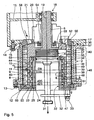
- agitator mill has in the usual way a stand 1, on which a cylindrical grinding container 2 can be attached.
- a stand 1 on which a cylindrical grinding container 2 can be attached.
- an electric drive motor 3 is housed, which is provided with a V-belt pulley 4, of which via V-belt 5 with a drive shaft 6 rotatably connected V-belt pulley 7 is rotationally driven.
- the grinding container 2 a cylindrical, a grinding chamber 8 surrounding container wall 9, which is surrounded by a substantially cylindrical cooling jacket 10, on.
- the container wall 9 and the cooling jacket 10 define a cooling space 11 between them.
- the lower end of the grinding chamber 8 is formed by an annular bottom plate 12, which is fastened to the grinding container 2 by means of screws 13.
- the grinding container 2 has an upper annular flange 14, by means of which it is attached to the underside of a support housing 15 by means of screws 16 which is mounted on the stator 1 of the agitator mill.
- the grinding chamber 8 is closed by means of a lid 17.
- the support housing 15 has a central bearing and seal housing 18 which is arranged coaxially to the central longitudinal axis 19 of the grinding container 2. This bearing and seal housing 18 is penetrated by the likewise coaxial to the axis 19 extending drive shaft 6, to which a stirrer 20 is mounted.
- a projecting into the grinding container 2 approximately pot-shaped, cylindrical inner stator 22 is arranged coaxially to the axis 19 an outer wall 23 and within this outer wall 23 has a cylindrical inner shell 24.
- the outer wall 23 and the inner shell 24 define between them a cooling space 25 of the inner stator 22.
- the cooling space 25 is supplied with cooling water via a cooling water supply port 26, which is discharged via a cooling water discharge port 27.
- the cooling space 11 of the grinding container 2 is supplied with cooling water via a cooling water supply pipe 28, which is discharged via a cooling water discharge pipe 29.
- a protective screen 30 is arranged, which is connected to a regrind discharge line 31.
- the drain line 31 is provided in the region of the bottom plate 12 with a retaining bracket 32 which is releasably connected by means of screws 33 with the bottom plate 12.
- the protective sieve 30 is sealed against the inner stator 22 by means of a seal 34 and can be pulled out after loosening the screws 33 together with the drain line 31 down from the inner stator.
- the agitator 20 is cup-shaped in its basic structure, ie it has a substantially annular cylindrical rotor 35. At its upper end, the agitator 20 has a lid-like end part 36 of the rotor 35. In the agitator 20, in the transition region between the lid-like end part 36 and the annular cylindrical, ie tubular rotor 35, a Mahlwhis stresses recirculator 37 is arranged.
- a (D9 - D35) / 2
- D9 is the diameter of the container wall 9, that is, the outer diameter of the grinding chamber 8 and wherein D35 denotes the outer diameter of the rotor 35, ie the inner diameter of the grinding chamber
- the inside of the container wall 9 is cylindrical smooth, so has no projecting into the annular grinding chamber 8 tools.
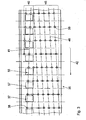
- projecting pin-shaped tools 38 are mounted on the likewise cylindrical outer side of the rotor 35 radially to the central longitudinal axis 19 in the grinding chamber 8 . They extend close to the container wall 9, to which they release only a structurally predetermined gap 39 with a gap width b. As Fig. 3 can be removed, the tools 38 are mounted helically on the rotor surface.
- the tools 38 which are arranged in the first region 40 assigned to the closure part 36 are arranged on a first helix 41 designed in such a way that they rotate on the agitator 20 and thus of the rotor 35 in the direction of rotation 42 on the auxiliary grinding bodies 43 with a diameter located in the grinding chamber 8 c a in the flow direction 44 of the material to be ground down, ie to the bottom plate 12 out, directed conveying action on the auxiliary grinding body 43 exercise.
- This first area 40 with the arrangement of the tools 38 on the first helix 41 extends approximately to the lower side of the return device 37, such as Fig. 3 is removable.
- the tools 38 are arranged on a second, oppositely directed helical line 46 so that they exert a pulse directed counter to the flow direction 44 of the millbase in the direction of rotation 42 on the grinding aid bodies 43 when the agitator 20 is driven ,
- Fig. 3 results in the circumferential direction of the rotor 35 adjacent tools 38 on both the first helical line 41 and on the second helix 46 in the direction of the central longitudinal axis 19 are arranged overlapping each other, so that upon rotation of the rotor 35, the container wall 9 completely from the Tools 38 is swept over.
- a ring-cylindrical Mahlgut-Ablite channel 47 is formed between the rotor 35 and the outer wall 23 of the inner stator 22 .
- pin-shaped stripping tools 48 attached on the outer wall 23 of the inner stator 22 .
- adjacent stripping tools 48 in the direction of the central longitudinal axis 19 are arranged overlapping each other, so that in one revolution of the rotor 35 whose wall is completely swept by these tools 48.
- the stripping tools 48 have opposite the inner stator 22, a gap 49, the gap width e is only as large as it is structurally necessary.
- the auxiliary grinding body 43 applies in relation to the diameter c: 4c ⁇ b ⁇ 6c, with the use of particularly small auxiliary grinding bodies 43 as the minimum boundary condition: 1.0 mm ⁇ b ⁇ 2.0 mm. Accordingly, for the gap width e of the gap 49 in relation to the diameter c, the auxiliary grinding body 43 is: 4c ⁇ e ⁇ 6c, whereby the following applies for extremely small auxiliary grinding bodies 43 as a minimum boundary condition: 1.0 mm ⁇ e ⁇ 2.0 mm. Because of this configuration, the tools 38 constantly swirl the grinding aid body packing in the grinding chamber 8. The scraper tools scrape due to the small gap width e the rotor 35 while driving it as it were. If Mahlös stresses 43 extremely small diameter c, so micro-Mahlos emotions be used, then applies to their diameter c: 20 microns ⁇ c ⁇ 100 microns.
- the grinding chamber 8 is connected to the discharge channel 47 by means of a deflection channel 50 whose width - as out Fig. 2 shows that corresponds approximately to the discharge channel 47. This deflection channel 50 thus surrounds the rotor 35 at its free lower end.
- the grinding chamber 8 is adjacent to the deflection channel 50 substantially closed by means of a radially extending to the axis 19 bottom surface 51, in the immediate vicinity of the lowest, so next adjacent tool 38 rotates, the distance g to the bottom surface 51 about the gap widths b and e corresponds. In this way, it is achieved that in this region, that is to say immediately before entry into the deflection channel 50, grinding aid bodies 43 are accelerated radially outwardly, ie they are conveyed away from the deflection channel 50.
- the cylindrical protective sieve 30 consists of a stack of annular discs 52, between each of which a separating gap 53 is released, whose width is smaller than the diameter c of the smallest grinding auxiliary body 43 used.
- the stack of annular discs 52 is the front side, so on the shaft 6 facing side, closed by a closure plate 54.
- the protective screen 30 is disposed inside the return device 37.
- grinding aid return channels 55 are formed in the return device 37.
- Their respective inlet opening 56 is located immediately adjacent to the return channel 47 and the protective screen 30.
- Their respective outlet opening 57 opens into the in the initial region of the grinding chamber 8, in the first region 40 of the helical arrangement of the tools 38th Wie Fig. 3 can be removed, the respective outlet openings 57 are - in relation to the direction of rotation 42 - immediately before one or more tools 38, so received back through a discharge channel 47 Mahltos stresses 43 immediately after their exit from the outlet opening 57 a delivery pulse in the flow direction 44.
- the ground material flows through the grinding chamber 8 corresponding to the flow direction 44 coming from the grinding material supply line 21 through a Mahlgut feed space 58 between the end portion 36 of the agitator 20 and the lid 17, the first portion 40 and the second portion 45 of the grinding chamber 8 down through the deflection channel 50 radially inwardly and from there through the grinding stock removal channel 47 up to a trained between the end part 36 and the inner stator 22, substantially radially inwardly directed to the protective sieve 30 AbströmKanal 59. Then it enters through the protective sieve 30 in the ground material drain line 31 and through this from the agitator mill.
- the material to be ground is ground in rotationally driven agitator 20 in cooperation with the auxiliary grinding bodies 43.
- the auxiliary grinding bodies 43 receive tangential pulses which convey them in the direction of the container wall 9.
- a compression of the auxiliary grinding bodies 43 occurs in the radially outer region of the grinding chamber 8, as indicated in the drawing. Due to the small width b of the gap 39 between the tools 38 and the container wall 9 no deposits of grinding auxiliary bodies 43 occur on the container wall 9; also Mahltos stresses 43 thrown there are repeatedly activated and taken away.
- Mahlosharm 43 get into the regrind discharge channel 47, they are there promoted by the stripping tools 48 with the ground material through the entire stripping channel 47. They are thrown off again by the return device 37 into the first region 40 of the grinding chamber 8.
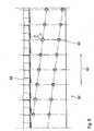
- FIG. 5 The embodiment according to Fig. 5 is different from the after Fig. 2 only in that in the rotor 35 'distributed over the axial length and over its circumference distributed through holes formed additional small Mahltos emotions return transport channels 60 are formed with a diameter h of 5.0 to 30.0 mm.
- the small Mahltos emotions return transport channels 60 are arranged on helical lines, wherein circumferentially adjacent channels 60 overlap each other, so that nevertheless arrived in the Mahlgut-discharge channel 47 and centrifuged on the rotor 35 Mahlosharm 43 mandatory on at least one such Pass channel 60, through which they can be thrown back into the outer grinding chamber 9.
- Fig. 7 is different from the after Fig. 2 only in that the protective sieve 30 'in a conventional manner one with the inner stator 22 has associated support body 61 which is provided with slot-shaped openings 62. On the outside of this support body 61, a very thin sheet or a film 63 is arranged, which is provided with very fine separation slots 64, whose width is not shown in the drawing in any case smaller than the diameter c of the smallest Mahlös stresses 43rd
- the agitator mill after Fig. 8 is different from the after Fig. 2 in that the rotor 35 'is the Mahltosterrorism return transport channels 60 according to the embodiment in Fig. 5 and the protective screen 30 'according to the embodiment according to Fig. 7 having.
- the design after Fig. 9 basically corresponds to the after Fig. 5 and 7 that is, the rotor 35 'is provided with the auxiliary grinding body return transport channels 60.
- the protective screen 30 is in this case not attached to the inner stator 22, but in the end part 36 of the rotor 35 ', in which a generally all protective screens 30, 30', 30" enclosing or receiving cylindrical recess 65 is formed .
- the protective screen 30 has a supporting body 66, which is connected to the terminal part 36 of the rotor 35 'by means of a screw 67.
- the supporting body 66 is provided with slot-shaped openings 62 and on its cylindrical outer periphery with a foil or a sheet metal 63 is enclosed in the support body 66.
- the ground material discharge line 31' extends in a sealed manner through the otherwise closed one upper end wall 70 of the inner stator 22 ', until just before the facing end wall 71 of the protective sieve 30 ". Between the regrind discharge line 31 'and this closure wall 71, a narrow gap 72 is formed. This The gap 72 usually has a width i which is smaller than the smallest diameter c of the auxiliary grinding bodies 43. The width i of the gap 72 must be so small that a sufficiently large pressure loss occurs here during the outflow of the ground material to be ground, so that the material to be ground passes through the Protection strainer 30 "drains off.
- the end wall 71 of this protective sieve 30 "opens frustoconically towards the end wall 70 and delimits at its radially outer region to the end wall 70 an annular gap 73 through which virtually no auxiliary grinding bodies 43 can penetrate during operation of the agitator mill Grinding aid bodies 43 are thrown outwards again through the annular gap 73 and enter the grinding aid return channels 55.
- the protective sieve 30 "with its foil or its metal sheet 63 is completely in axial overlap with the grinding aid body return channels 55. Should any grinding aid bodies 43 reach the area of the protective sieve 30", then They are also thrown from their film-forming their cylindrical circumference film or sheet 63 in the return channels 55.
- the millbase has a very gerihge viscosity in the range of 1 to 100 mPas.
Landscapes
- Engineering & Computer Science (AREA)
- Food Science & Technology (AREA)
- Crushing And Grinding (AREA)
Priority Applications (1)
| Application Number | Priority Date | Filing Date | Title |
|---|---|---|---|
| EP08013806A EP1992412B1 (de) | 2005-10-11 | 2005-10-11 | Rührwerksmühle |
Applications Claiming Priority (1)
| Application Number | Priority Date | Filing Date | Title |
|---|---|---|---|
| PCT/EP2005/010910 WO2007042059A1 (de) | 2005-10-11 | 2005-10-11 | Rührwerksmühle |
Related Child Applications (2)
| Application Number | Title | Priority Date | Filing Date |
|---|---|---|---|
| EP08013806A Division EP1992412B1 (de) | 2005-10-11 | 2005-10-11 | Rührwerksmühle |
| EP08013806.8 Division-Into | 2008-08-01 |
Publications (2)
| Publication Number | Publication Date |
|---|---|
| EP1943022A1 EP1943022A1 (de) | 2008-07-16 |
| EP1943022B1 true EP1943022B1 (de) | 2010-03-31 |
Family
ID=35519817
Family Applications (2)
| Application Number | Title | Priority Date | Filing Date |
|---|---|---|---|
| EP08013806A Not-in-force EP1992412B1 (de) | 2005-10-11 | 2005-10-11 | Rührwerksmühle |
| EP05792291A Not-in-force EP1943022B1 (de) | 2005-10-11 | 2005-10-11 | Rührwerksmühle |
Family Applications Before (1)
| Application Number | Title | Priority Date | Filing Date |
|---|---|---|---|
| EP08013806A Not-in-force EP1992412B1 (de) | 2005-10-11 | 2005-10-11 | Rührwerksmühle |
Country Status (7)
| Country | Link |
|---|---|
| US (2) | US20090179099A1 (zh) |
| EP (2) | EP1992412B1 (zh) |
| JP (1) | JP2009511255A (zh) |
| KR (2) | KR101230133B1 (zh) |
| CN (1) | CN101287554B (zh) |
| DE (2) | DE502005009341D1 (zh) |
| WO (1) | WO2007042059A1 (zh) |
Cited By (2)
| Publication number | Priority date | Publication date | Assignee | Title |
|---|---|---|---|---|
| DE102015107789B3 (de) * | 2015-05-19 | 2016-07-07 | Netzsch-Feinmahltechnik Gmbh | Rührwerkskugelmühle und Verfahren zum Betreiben einer Rührwerkskugelmühle |
| EP4032615A1 (de) | 2021-01-25 | 2022-07-27 | Wilhelm Niemann GmbH & Co KG | Rührwerksmühle |
Families Citing this family (26)
| Publication number | Priority date | Publication date | Assignee | Title |
|---|---|---|---|---|
| KR100928076B1 (ko) * | 2008-12-19 | 2009-11-23 | (주)제이분체 | 나노 분쇄기 |
| CH700446A1 (de) * | 2009-02-24 | 2010-08-31 | Bachofen Willy A Ag | Rührwerkskugelmühle. |
| KR100921189B1 (ko) * | 2009-02-25 | 2009-10-13 | 베스트화학기계공업(주) | 퍼펙트 밀 |
| EP2683487B1 (de) | 2011-03-11 | 2016-03-09 | Willy A. Bachofen AG | Rührwerkskugelmühle |
| CN103480463B (zh) * | 2012-06-14 | 2015-01-28 | 谢小飞 | 一种离心式无隔网料珠分离介质搅拌磨 |
| CN102688793B (zh) * | 2012-06-14 | 2014-04-16 | 昆山聚贝机械设计有限公司 | 珠磨机 |
| CN102814217A (zh) * | 2012-08-31 | 2012-12-12 | 常州市龙鑫化工机械有限公司 | 一种高效再循环珠磨机 |
| CN102837252B (zh) * | 2012-08-31 | 2014-09-24 | 常州市龙鑫化工机械有限公司 | 一种具有机械密封保护装置的再循环珠磨机 |
| CN103480462B (zh) * | 2013-01-10 | 2015-12-09 | 上海法孚莱能源技术有限公司 | 篮式研磨机 |
| CN103418460B (zh) * | 2013-04-27 | 2016-01-13 | 占天义 | 一种研磨装置 |
| DE102015105804A1 (de) * | 2015-04-16 | 2016-10-20 | Netzsch-Feinmahltechnik Gmbh | Rührwerkskugelmühle |
| EP3283204B1 (de) * | 2015-04-17 | 2020-12-23 | Bühler AG | Vorrichtung und verfahren zum mischen, insbesondere zum dispergieren |
| DE102015112760B4 (de) * | 2015-08-04 | 2017-03-23 | Netzsch Feinmahltechnik Gmbh | Trennvorrichtung, Rührwerkskugelmühle und Verfahren zum Klassieren von Produktgemischen |
| US10500591B2 (en) | 2015-09-02 | 2019-12-10 | Air Products And Chemicals, Inc. | System and method for the preparation of a feedstock |
| CN107570276A (zh) * | 2017-09-14 | 2018-01-12 | 江苏博砚电子科技有限公司 | 一种高精细分散砂磨机 |
| EP3536406A1 (de) | 2018-03-07 | 2019-09-11 | Bühler AG | Rührwerksmühle |
| EP3536405A1 (de) | 2018-03-07 | 2019-09-11 | Bühler AG | Rührwerksmühle mit asynchroner stiftanordnung |
| DE102018122408B4 (de) * | 2018-09-13 | 2023-11-09 | Netzsch Feinmahltechnik Gmbh | Rührwerkskugelmühle, Verschleißschutzhülse für eine Rührwerkskugelmühle und Verfahren zum Herstellen einer Verschleißschutzhülse für eine Rührwerkskugelmühle |
| DE102018122395A1 (de) * | 2018-09-13 | 2020-03-19 | Netzsch Feinmahltechnik Gmbh | Rührwelle für eine Rührwerkskugelmühle, Rührwerkskugelmühle und Verfahren zum Herstellen einer Rührwelle für eine Rührwerkskugelmühle |
| CN109248744A (zh) * | 2018-10-31 | 2019-01-22 | 东莞市琅菱机械有限公司 | 一种可旋转的研磨机 |
| CN109433340B (zh) * | 2018-11-12 | 2020-10-09 | 长沙万荣粉体设备科技有限公司 | 一种立式磨机 |
| EP3799960A1 (de) | 2019-10-01 | 2021-04-07 | Bühler AG | Rührwerksmühle |
| DE102020103848A1 (de) | 2020-02-14 | 2021-08-19 | Netzsch-Feinmahltechnik Gmbh | Temperiertes Bauteil und Verfahren zur Herstellung eines temperierten Bauteils |
| CN114096354B (zh) * | 2020-03-27 | 2023-08-15 | 布勒股份公司 | 搅拌球磨机 |
| EP4049758A1 (de) | 2021-02-24 | 2022-08-31 | Bühler AG | Verschleissfester rotor |
| CN115364959A (zh) * | 2022-08-24 | 2022-11-22 | 天蓝颜料(山东)有限公司 | 一种立式研磨机 |
Family Cites Families (20)
| Publication number | Priority date | Publication date | Assignee | Title |
|---|---|---|---|---|
| BE552321A (zh) * | 1950-05-24 | |||
| GB1038153A (en) * | 1963-05-23 | 1966-08-10 | Torrance And Sons Ltd | Method of and apparatus for grinding or grinding and dispersing materials comprisingsolid particles in a liquid |
| US4394981A (en) * | 1980-07-25 | 1983-07-26 | Schold George R | Apparatus for dispersing finely divided solid particles in a liquid vehicle with a mechanism for reducing screen clogging |
| DE3437866A1 (de) | 1984-10-16 | 1986-04-17 | Basf Farben + Fasern Ag, 2000 Hamburg | Dispergierverfahren und ruehrwerksmuehle zu seiner durchfuehrung |
| JPS62210062A (ja) * | 1986-03-10 | 1987-09-16 | 川崎重工業株式会社 | 固体材料の微粉砕方法および装置 |
| DE3716587C1 (de) * | 1987-05-18 | 1988-04-28 | Draiswerke Gmbh | Ruehrwerksmuehle |
| JPS6443337A (en) * | 1987-08-11 | 1989-02-15 | Asada Tekko Kk | Continuous medium-type dispersing and stirring machine |
| DE3838981A1 (de) * | 1988-11-18 | 1990-05-23 | Eirich Walter | Ruehrwerkskugelmuehle |
| DE4009092C1 (zh) * | 1990-03-21 | 1991-05-23 | Erich Netzsch Gmbh & Co Holding Kg, 8672 Selb, De | |
| DE4109332A1 (de) | 1991-03-21 | 1992-09-24 | Netzsch Erich Holding | Ruehrwerksmuehle |
| JPH07106310B2 (ja) | 1991-12-13 | 1995-11-15 | 株式会社井上製作所 | 媒体分散機 |
| US5346124A (en) * | 1993-07-01 | 1994-09-13 | Moore Business Forms, Inc. | Certified mailer |
| JPH09164342A (ja) * | 1995-12-15 | 1997-06-24 | Mitsui Mining Co Ltd | 粉砕機 |
| US5853132A (en) * | 1996-03-06 | 1998-12-29 | Fuji Photo Film Co., Ltd. | Dispersing machine |
| DE19638354A1 (de) * | 1996-09-19 | 1998-03-26 | Draiswerke Inc Mahwah | Rührwerksmühle |
| DE19819967B4 (de) * | 1998-05-05 | 2007-04-26 | BüHLER GMBH | Rührwerksmühle |
| JP3464387B2 (ja) * | 1998-06-15 | 2003-11-10 | 太陽誘電株式会社 | セラミックス粒子の粉砕装置及び粉砕方法 |
| DE29814714U1 (de) * | 1998-08-17 | 1998-12-10 | Draiswerke Gmbh | Rührwerksmühle |
| DE10011579B4 (de) * | 2000-03-09 | 2007-06-06 | BüHLER GMBH | Rührwerksmühle |
| JP2003047871A (ja) * | 2001-08-09 | 2003-02-18 | Inoue Mfg Inc | 湿式媒体分散機 |
-
2005
- 2005-10-11 EP EP08013806A patent/EP1992412B1/de not_active Not-in-force
- 2005-10-11 WO PCT/EP2005/010910 patent/WO2007042059A1/de active Application Filing
- 2005-10-11 JP JP2008534872A patent/JP2009511255A/ja active Pending
- 2005-10-11 DE DE502005009341T patent/DE502005009341D1/de active Active
- 2005-10-11 KR KR1020107010389A patent/KR101230133B1/ko not_active IP Right Cessation
- 2005-10-11 DE DE502005008983T patent/DE502005008983D1/de active Active
- 2005-10-11 CN CN2005800518113A patent/CN101287554B/zh not_active Expired - Fee Related
- 2005-10-11 EP EP05792291A patent/EP1943022B1/de not_active Not-in-force
- 2005-10-11 US US12/089,849 patent/US20090179099A1/en not_active Abandoned
- 2005-10-11 KR KR1020087010450A patent/KR101128541B1/ko active IP Right Grant
-
2010
- 2010-07-20 US US12/840,242 patent/US7931222B2/en not_active Expired - Fee Related
Cited By (5)
| Publication number | Priority date | Publication date | Assignee | Title |
|---|---|---|---|---|
| DE102015107789B3 (de) * | 2015-05-19 | 2016-07-07 | Netzsch-Feinmahltechnik Gmbh | Rührwerkskugelmühle und Verfahren zum Betreiben einer Rührwerkskugelmühle |
| WO2016184445A1 (de) | 2015-05-19 | 2016-11-24 | Netzsch-Feinmahltechnik Gmbh | Rührwerkskugelmühle und verfahren zum betreiben einer rührwerkskugelmühle |
| EP4032615A1 (de) | 2021-01-25 | 2022-07-27 | Wilhelm Niemann GmbH & Co KG | Rührwerksmühle |
| DE102021101527A1 (de) | 2021-01-25 | 2022-07-28 | Wilhelm Niemann Gmbh & Co. | Rührwerksmühle |
| DE102021101527B4 (de) | 2021-01-25 | 2023-05-17 | Wilhelm Niemann Gmbh & Co. | Rührwerksmühle |
Also Published As
| Publication number | Publication date |
|---|---|
| KR101230133B1 (ko) | 2013-02-05 |
| DE502005008983D1 (de) | 2010-03-25 |
| DE502005009341D1 (de) | 2010-05-12 |
| JP2009511255A (ja) | 2009-03-19 |
| US20100282884A1 (en) | 2010-11-11 |
| KR101128541B1 (ko) | 2012-03-23 |
| KR20080069979A (ko) | 2008-07-29 |
| US20090179099A1 (en) | 2009-07-16 |
| EP1992412A1 (de) | 2008-11-19 |
| WO2007042059A1 (de) | 2007-04-19 |
| CN101287554B (zh) | 2010-06-09 |
| CN101287554A (zh) | 2008-10-15 |
| EP1992412B1 (de) | 2010-02-03 |
| US7931222B2 (en) | 2011-04-26 |
| EP1943022A1 (de) | 2008-07-16 |
| KR20100077017A (ko) | 2010-07-06 |
Similar Documents
| Publication | Publication Date | Title |
|---|---|---|
| EP1943022B1 (de) | Rührwerksmühle | |
| EP2178642B1 (de) | Rührwerksmühle | |
| EP0370022B1 (de) | Rührwerksmühle | |
| EP2327479B1 (de) | Rührwerkskugelmühle | |
| DE4432200C1 (de) | Rührwerksmühle | |
| DE3015833C2 (zh) | ||
| EP0058886B1 (de) | Rührwerksmühle | |
| EP2178643B1 (de) | Rührwerksmühle | |
| EP1724022B1 (de) | Rührwerksmühle | |
| DE10011579B4 (de) | Rührwerksmühle | |
| EP0439826A1 (de) | Rührwerksmühle | |
| EP3573762B1 (de) | Rührwerksmühle | |
| EP0913200B1 (de) | Rührwerksmühle | |
| EP0824964A1 (de) | Rührwerksmühle | |
| EP0504836B1 (de) | Rührwerksmühle | |
| EP0640397A2 (de) | Rührwerksmühle | |
| AT398282B (de) | Zentrifuge | |
| EP0645179B1 (de) | Reibmühle und Mischer, der diese Reibmühle enthält | |
| EP2683487B1 (de) | Rührwerkskugelmühle | |
| CH687238A5 (de) | Ruehrwerksmuehle. | |
| DE19834397B4 (de) | Rührwerksmühle | |
| DE4142213C2 (de) | Rührwerksmühle | |
| EP1724021A1 (de) | Rührwerksmühle | |
| DE4419919C1 (de) | Rührwerksmühle | |
| WO2019170663A1 (de) | Rührwerksmühle |
Legal Events
| Date | Code | Title | Description |
|---|---|---|---|
| PUAI | Public reference made under article 153(3) epc to a published international application that has entered the european phase |
Free format text: ORIGINAL CODE: 0009012 |
|
| 17P | Request for examination filed |
Effective date: 20080228 |
|
| AK | Designated contracting states |
Kind code of ref document: A1 Designated state(s): CH DE LI |
|
| RBV | Designated contracting states (corrected) |
Designated state(s): CH DE LI |
|
| GRAP | Despatch of communication of intention to grant a patent |
Free format text: ORIGINAL CODE: EPIDOSNIGR1 |
|
| DAX | Request for extension of the european patent (deleted) | ||
| GRAS | Grant fee paid |
Free format text: ORIGINAL CODE: EPIDOSNIGR3 |
|
| GRAA | (expected) grant |
Free format text: ORIGINAL CODE: 0009210 |
|
| AK | Designated contracting states |
Kind code of ref document: B1 Designated state(s): CH DE LI |
|
| REG | Reference to a national code |
Ref country code: CH Ref legal event code: EP |
|
| REF | Corresponds to: |
Ref document number: 502005009341 Country of ref document: DE Date of ref document: 20100512 Kind code of ref document: P |
|
| PLBE | No opposition filed within time limit |
Free format text: ORIGINAL CODE: 0009261 |
|
| STAA | Information on the status of an ep patent application or granted ep patent |
Free format text: STATUS: NO OPPOSITION FILED WITHIN TIME LIMIT |
|
| 26N | No opposition filed |
Effective date: 20110104 |
|
| REG | Reference to a national code |
Ref country code: DE Ref legal event code: R082 Ref document number: 502005009341 Country of ref document: DE Ref country code: DE Ref legal event code: R082 Ref document number: 502005009341 Country of ref document: DE Representative=s name: VOSSIUS & PARTNER PATENTANWAELTE RECHTSANWAELT, DE |
|
| REG | Reference to a national code |
Ref country code: DE Ref legal event code: R082 Ref document number: 502005009341 Country of ref document: DE Representative=s name: VOSSIUS & PARTNER PATENTANWAELTE RECHTSANWAELT, DE |
|
| PGFP | Annual fee paid to national office [announced via postgrant information from national office to epo] |
Ref country code: DE Payment date: 20211020 Year of fee payment: 17 |
|
| PGFP | Annual fee paid to national office [announced via postgrant information from national office to epo] |
Ref country code: CH Payment date: 20211022 Year of fee payment: 17 |
|
| REG | Reference to a national code |
Ref country code: DE Ref legal event code: R119 Ref document number: 502005009341 Country of ref document: DE |
|
| REG | Reference to a national code |
Ref country code: CH Ref legal event code: PL |
|
| PG25 | Lapsed in a contracting state [announced via postgrant information from national office to epo] |
Ref country code: LI Free format text: LAPSE BECAUSE OF NON-PAYMENT OF DUE FEES Effective date: 20221031 Ref country code: DE Free format text: LAPSE BECAUSE OF NON-PAYMENT OF DUE FEES Effective date: 20230503 Ref country code: CH Free format text: LAPSE BECAUSE OF NON-PAYMENT OF DUE FEES Effective date: 20221031 |