EP0640397A2 - Rührwerksmühle - Google Patents
Rührwerksmühle Download PDFInfo
- Publication number
- EP0640397A2 EP0640397A2 EP94113127A EP94113127A EP0640397A2 EP 0640397 A2 EP0640397 A2 EP 0640397A2 EP 94113127 A EP94113127 A EP 94113127A EP 94113127 A EP94113127 A EP 94113127A EP 0640397 A2 EP0640397 A2 EP 0640397A2
- Authority
- EP
- European Patent Office
- Prior art keywords
- separating device
- agitator mill
- mill according
- static
- passage opening
- Prior art date
- Legal status (The legal status is an assumption and is not a legal conclusion. Google has not performed a legal analysis and makes no representation as to the accuracy of the status listed.)
- Granted
Links
Images

Classifications
-
- B—PERFORMING OPERATIONS; TRANSPORTING
- B02—CRUSHING, PULVERISING, OR DISINTEGRATING; PREPARATORY TREATMENT OF GRAIN FOR MILLING
- B02C—CRUSHING, PULVERISING, OR DISINTEGRATING IN GENERAL; MILLING GRAIN
- B02C17/00—Disintegrating by tumbling mills, i.e. mills having a container charged with the material to be disintegrated with or without special disintegrating members such as pebbles or balls
- B02C17/16—Mills in which a fixed container houses stirring means tumbling the charge
- B02C17/161—Arrangements for separating milling media and ground material
-
- B—PERFORMING OPERATIONS; TRANSPORTING
- B02—CRUSHING, PULVERISING, OR DISINTEGRATING; PREPARATORY TREATMENT OF GRAIN FOR MILLING
- B02C—CRUSHING, PULVERISING, OR DISINTEGRATING IN GENERAL; MILLING GRAIN
- B02C17/00—Disintegrating by tumbling mills, i.e. mills having a container charged with the material to be disintegrated with or without special disintegrating members such as pebbles or balls
- B02C17/16—Mills in which a fixed container houses stirring means tumbling the charge
- B02C17/166—Mills in which a fixed container houses stirring means tumbling the charge of the annular gap type
Definitions
- Agitator mills of the type mentioned above are known, for example, from DE-GM 90 04 117.8 and DE-A-40 10 926.7.
- the static separating device is in this case formed by a sieve, preferably a slotted sieve, which is arranged either rotating or stationary on the outlet side of the grinding chamber.
- a disadvantage of such designs is that the sieve can become clogged by auxiliary grinding bodies and their fragments in the course of a longer period of operation and, in addition, when the agitator mill is switched off, the grinding material suspension (together with auxiliary grinding bodies and their fragments) becomes attached to the sieve, which can be disadvantageous Cases closes the passage openings of the static separator so far that restarting the agitator mill before intensive cleaning or changing the sieve is impossible.
- DD-A 45 700 also discloses a dispersing device in which a conically shaped ring sieve is connected to the agitator shaft, which tapers downward into the suction area of a stirring disk attached to the agitator shaft.
- a free annular gap is provided between the lower end of the sieve and the agitator shaft, which is two to three times as wide as the diameter of the largest grinding media.
- the invention has for its object to design an agitator mill of the type mentioned in such a way that on the one hand an operationally reliable, trouble-free separation of auxiliary grinding bodies and their fragments from the ground material suspension takes place and on the other hand maintenance work, in particular on the static separating device, is greatly reduced.
- a dynamic separating device is also provided on the outlet side of the grinding chamber, which has at least one passage opening delimited by elements which are movable relative to one another and which is dimensioned in such a way that the ground material passes, but the auxiliary grinding bodies be held back.
- the agitator mill can be restarted without high pressure build-up in the mill in that in this case the dynamic separating device frees itself up and thus the ground material suspension in the starting phase can flow through the dynamic separation device.
- the suspension dried on the static separating device is loosened automatically (ie without any special maintenance measure) and the separating device is thus flushed out after a short time, so that an additional cleaning process which leads to an interruption in operation is unnecessary.
- the free passage opening of the static separation device is added to the free passage opening of the dynamic separation device in normal operation, the total passage opening of the static and dynamic separation device is thus relatively large, the pressure build-up in the operation of the agitator mill remains small. This largely prevents fragments of auxiliary grinding bodies from being pressed into the static or dynamic separating device.
- the combined separating device also offers the possibility of processing pseudoplastic or highly thixotropic products without increasing pressure, since the dynamic separating device reduces thixotropies or structural viscosities due to the resulting shear rate.
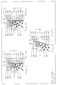
- the agitator mill shown in FIG. 1 contains a housing 1 and a rotor 2.
- the hub body 21 of the rotor 2 is seated on a shaft 3, which is mounted in a bearing pot 5 of the housing 1 by means of a bearing 4 and by a (not illustrated) drive motor from is driven above.
- a rotor 22 which is firmly connected to the hub body 21, projects as a displacement body into a recess 13 in the housing 1.
- the housing 1 In its lower, funnel-shaped area, the housing 1 forms a feed chamber 8 for the regrind fed in the direction of the arrow 7.
- the feed chamber 8 is connected to the grinding chamber 6 via an annular channel 9 and a material inlet 15.
- a static separating device formed by a slotted screen 20 and on the other hand a dynamic separating device designed as a friction gap 25 is provided. The details of these two separation devices are explained in detail with reference to FIG. 2.
- the ground material After passing the slotted screen 20 or the friction gap 25, the ground material is crushed through an outlet channel 23 removed (arrow 16).
- the auxiliary grinding bodies pass from the outlet side 26 of the grinding chamber via return channels 34 to the inlet side of the grinding chamber 6, ie to the area of the material inlet 15.
- FIG. 2 shows the details of the static and dynamic separation device of the agitator mill according to FIG. 1.
- the static separating device is formed by the slotted screen 20, which is cylindrical and is arranged coaxially to the axis 10 of the shaft 3.
- the slotted screen 20 is made of triangular profile wire and has separating gaps 20a.
- These passage openings (separating gaps 20a) of the static separating device (slotted sieve 20), which are delimited by elements which are not movable relative to one another, are dimensioned in such a way that the ground material passes through, but the auxiliary grinding bodies 27 are retained.
- the slotted screen 20 is clamped between two hub parts 28 and 29 which are fixedly connected to the shaft 3. It therefore rotates with the shaft 3 and the rotor 22.
- Axial channels 30 are provided in the hub part 29, through which the ground material reaches the outlet channel 23 from the space 31 which is not closed by the slotted screen 20.
- the friction gap 25 forming the dynamic separating device is delimited by a ring 32 connected to the housing 1 and accordingly arranged in a stationary manner, and by a ring 33 carried and accordingly rotating by the hub part 29.
- the two rings 32, 33 are made of wear-resistant material.
- the passage opening formed by the annular gap 25 is in its Size so that the crushed ground material passes through, the grinding aid 27 are held against it.
- the friction gap 25 connects the outlet side 26 of the grinding chamber 6 directly to the outlet channel 23.
- the ground material comminuted in the grinding chamber 6 flows from the outlet side 26 of the grinding chamber through the slotted screen 20 as well as through the friction gap 25 into the outlet channel 23, while the auxiliary grinding bodies 27 are retained. If after a longer standstill of the agitator mill the two separating devices are clogged by dried millbase suspension, when the mill is started again by the rotary movement of the ring 33 relative to the stationary ring 32 the friction gap 25 is immediately exposed so that the millbase suspension flows from the outlet side 26 to the outlet channel 23 can. The flow movement thereby set in on the outlet side 26 loosens the millbase suspension dried on the slotted screen 20 in a short time, so that the slotted screen 20 is also flushed out after a short time. During further operation, both the static separating device and the dynamic separating device then contribute to separating the ground material suspension from the auxiliary grinding bodies, which in view of the relatively large total passage opening of the two separating devices leads to a low pressure build-up inside the mill.
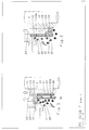
- the same reference numerals are used for the same elements.
- the ring 32 of the dynamic separation device is in a corresponding in this embodiment large dimensioned recess 35 of the housing 1 floating. In this way, eccentric manufacturing tolerances can be compensated, which enables the setting of a very narrow friction gap 25.
- the exemplary embodiment according to FIG. 4 differs from the variant shown in FIG. 2 by the use of a conical slotted screen 20.
- centrifugal vanes 36 are arranged at a radial distance in front of the slotted sieve 20, which swirl the ground material suspension in the entrance area of the slotted sieve 20 and thus delay clogging of the slotted sieve 20.
- centrifugal blades 36 can be helical and can be arranged so that dragged auxiliary grinding bodies 27 are removed from the dynamic separating device, i.e. are promoted away from the friction gap 25. In this way, in particular the wear of the rings 32 and 33 delimiting the friction gap can be reduced.
- FIG. 6 shows a variant in which the slotted screen 20 is arranged in a fixed manner between the housing 1 and a component 37 which is also fixed to the housing.
- the component 37 also carries the stationary ring 32 of the dynamic separation device, the rotating ring 33 of which is supported by the hub part 29 which is connected to the shaft 3 in a rotationally fixed manner.
- the space 38 located on the downstream side of the slotted screen 20 and the friction gap 25 communicates with the outlet duct 23.
- the gap widths of the dynamic friction gap 25 and the gap sieve 20 are chosen between 0.05 mm and 3 mm in the agitator mill according to the invention, depending on the application.
- the friction gap expediently has a width which is 1/4 to 1/3 of the diameter of the auxiliary grinding bodies.
- the passage opening of the static separation device and the passage opening of the dynamic separation device can be dimensioned differently in this case.
- the elements of the slotted screen 20 delimiting the separating gaps 20a can have a triangular shape (see FIGS. 2, 3, 5, 6) or a rectangular shape (see FIG. 4).
Landscapes
- Engineering & Computer Science (AREA)
- Food Science & Technology (AREA)
- Crushing And Grinding (AREA)
- Disintegrating Or Milling (AREA)
Abstract
Description
- Die Erfindung betrifft eine Rührwerksmühle zur Naßzerkleinerung, enthaltend
- a) einen Mahlraum, dem auf seiner Einlaßseite frisches Mahlgut zugeführt und von dessen Auslaßseite zerkleinertes Mahlgut abgezogen wird,
- b) sowie eine auf der Auslaßseite des Mahlraumes angeordnete statische Trenneinrichtung, die wenigstens eine von relativ zueinander nicht beweglichen Elementen begrenzte Durchtrittsöffnung aufweist, die in ihrer Weite so bemessen ist, daß das zerkleinerte Mahlgut hindurchtritt, die Mahlhilfskörper jedoch zurückgehalten werden.
- Rührwerksmühlen der vorstehend genannten Gattung sind beispielsweise durch das DE-GM 90 04 117.8 sowie die DE-A-40 10 926.7 bekannt.
- Die statische Trenneinrichtung wird hierbei durch ein Sieb, vorzugsweise ein Spaltsieb, gebildet, das entweder rotierend oder stationär auf der Auslaßseite des Mahlraumes angeordnet ist. Nachteilig ist bei derartigen Ausführungen, daß das Sieb im Laufe eines längeren Betriebes durch Mahlhilfskörper sowie deren Bruchstücke verstopft werden kann und außerdem beim Abstellen der Rührwerksmühle ein Ansetzen und Austrocknen der Mahlgutsuspension (zusammen mit Mahlhilfskörpern und deren Bruchstücken) am Sieb erfolgen kann, was in ungünstigen Fällen die Durchtrittsöffnungen der statischen Trenneinrichtung so weit verschließt, daß ein Wiederanfahren der Rührwerksmühle vor einer intensiven Reinigung oder einem Auswechseln des Siebes ausgeschlossen ist. Bei sehr engen Durchtrittsöffnungen der statischen Trenneinrichtung ergeben sich ferner im Betrieb hohe Druckwerte und hohe Strömungsgeschwindigkeiten, wodurch Bruchstücke von Mahlhilfskörpern in die Durchtrittsöffnungen gedrückt werden und die Funktion der Trenneinrichtung wesentlich beeinträchtigt wird.
- Soweit bei den eingangs genannten bekannten Ausführungen die statische Trenneinrichtung rotierend angeordnet ist, befindet sich zwischen dieser rotierenden Trenneinrichtung und dem benachbarten stationären Gehäuse ein Dichtspalt, der zweckmäßig in seiner Größe einstellbar ist (vgl. etwa Fig.1 der DE-A-40 10 926.7). Die Weite eines solchen Dichtspaltes wird dabei so eng eingestellt, daß weder Mahlhilfskörper noch Mahlgut hindurchtreten können.
- Durch die DD-A 45 700 ist weiterhin eine Dispergiervorrichtung bekannt, bei der mit der Rührwerkswelle ein konisch geformtes Ringsieb verbunden ist, das sich nach unten bis in den Sogbereich einer auf der Rührwerkswelle angebrachten Rührscheibe verjüngt. Zwischen dem unteren Ende des Siebes und der Rührwerkswelle ist hierbei ein freier Ringspalt vorgesehen, der zwei- bis dreimal so breit ist wie der Durchmesser der größten Mahlkörper. Durch diesen Ringspalt kann im Betrieb nicht nur die zurückfließende Suspension strömen, sondern angesichts der Breite des Ringraumes können auch Mahlkörper, die beim An- oder Abstellen der Dispergiervorrichtung in das Gebiet des Ringraumes kommen, durch den Ringspalt hindurchtreten.
- Der Erfindung liegt die Aufgabe zugrunde, eine Rührwerksmühle der eingangs genannten Gattung so auszubilden, daß einerseits eine betriebssichere, störungsfreie Abtrennung von Mahlhilfskörpern und deren Bruchstücken aus der Mahlgutsuspension erfolgt und andererseits Wartungsarbeiten, insbesondere an der statischen Trenneinrichtung, stark verringert werden.
- Diese Aufgabe wird erfindungsgemäß dadurch gelöst, daß auf der Auslaßseite des Mahlraumes außerdem auch eine dynamische Trenneinrichtung vorgesehen ist, die wenigstens eine von relativ zueinander beweglichen Elementen begrenzte Durchtrittsöffnung aufweist, die in ihrer Weite so bemessen ist, daß das zerkleinerte Mahlgut hindurchtritt, die Mahlhilfskörper jedoch zurückgehalten werden.
- Für die erfindungsgemäße Rührwerksmühle ist somit die Kombination einer statischen und einer dynamischen Trenneinrichtung charakteristisch. Wie die der Erfindung zugrundeliegenden umfangreichen Versuche zeigten, läßt sich durch eine solche Kombination eine betriebssichere und fast wartungsfreie Trennung von Suspension und Mahlhilfskörpern erreichen, da sich die statische und die dynamische Trenneinrichtung bei den unterschiedlichen Betriebsbedingungen in idealer Weise ergänzen.
- So ist auch beim Austrocknen der statischen Trenneinrichtung ein Wiederanfahren der Rührwerksmühle ohne hohen Druckaufbau innerhalb der Mühle dadurch möglich, daß sich in diesem Falle die dynamische Trenneinrichtung freiarbeitet und damit in der Startphase die Mahlgutsuspension durch die dynamische Trenneinrichtung strömen kann. Hierbei wird gleichzeitig selbsttätig (d.h. ohne besondere Wartungsmaßnahme) die an der statischen Trenneinrichtung angetrocknete Suspension gelöst und damit die Trenneinrichtung nach kurzer Zeit freigespült, so daß sich ein zusätzlicher, zur Betriebsunterbrechung führender Reinigungsvorgang erübrigt.
- Da andererseits im Normalbetrieb zur freien Durchtrittsöffnung der dynamischen Trenneinrichtung die freie Durchtrittsöffnung der statischen Trenneinrichtung hinzukommt, die gesamte Durchtrittsöffnung der statischen und dynamischen Trenneinrichtung somit verhältnismäßig groß ist, bleibt der Druckaufbau im Betrieb- der Rührwerksmühle klein. Dadurch wird weitgehend vermieden, daß Bruchstücke von Mahlhilfskörpern in die statische oder dynamische Trenneinrichtung gedrückt werden. Die kombinierte Trenneinrichtung bietet ferner die Möglichkeit, auch strukturviskose bzw. stark thixotrope Produkte ohne erhöhten Druckaufbau zu verarbeiten, da die dynamische Trenneinrichtung durch das entstehende Schergefälle Thixotropien bzw. Strukturviskositäten abbaut.
- Zweckmäßige Ausgestaltungen der Erfindung sind Gegenstand der Unteransprüche und werden im Zusammenhang mit der Beschreibung einiger in der Zeichnung veranschaulichter Ausführungsbeispiele erläutert. In der Zeichnung zeigen
- Fig.1
- einen Vertikalschnitt durch ein erstes Ausführungsbeispiel der erfindungsgemäßen Rührwerksmühle,
- Fig.2
- eine Teildarstellung (in vergrößertem Maßstab) der statischen und dynamischen Trenneinrichtung der Rührwerksmühle gemäß Fig.1,
- Fig.3 bis 6
- Varianten der Anordnung gemäß Fig.2.
- Die in Fig.1 dargestellte Rührwerksmühle enthält ein Gehäuse 1 und einen Rotor 2. Der Nabenkörper 21 des Rotors 2 sitzt auf einer Welle 3, die mittels eines Lagers 4 in einem Lagertopf 5 des Gehäuses 1 gelagert und von einem (nicht veranschaulichten) Antriebsmotor von oben her angetrieben ist.
- Ein mit dem Nabenkörper 21 fest verbundener Rotor 22 ragt als Verdrängungskörper in eine Ausnehmung 13 des Gehäuses 1. Die Umfangswand 11 dieser Ausnehmung 13 begrenzt zusammen mit der Umfangswand 14 des Rotors 22 einen spaltförmig ausgebildeten Mahlraum 6.
- Das Gehäuse 1 bildet in seinem unteren, trichterförmig ausgebildeten Bereich einen Zuführraum 8 für das in Richtung des Pfeiles 7 zugeführte Mahlgut. Der Zuführraum 8 steht über einen Ringkanal 9 und einen Guteinlaß 15 mit dem Mahlraum 6 in Verbindung. Auf der Auslaßseite des Mahlraumes 6 ist einerseits eine durch ein Spaltsieb 20 gebildete statische Trenneinrichtung und andererseits eine als Reibspalt 25 ausgebildete dynamische Trenneinrichtung vorgesehen. Die Einzelheiten dieser beiden Trenneinrichtungen werden anhand der Fig.2 noch im einzelnen erläutert.
- Nach Passieren des Spaltsiebes 20 bzw. des Reibspaltes 25 wird das zerkleinerte Mahlgut über einen Auslaßkanal 23 abgeführt (Pfeil 16). Die Mahlhilfskörper gelangen demgegenüber von der Auslaßseite 26 des Mahlraumes über Rückführkanäle 34 zur Einlaßseite des Mahlraumes 6, d.h. zum Bereich des Guteinlasses 15.
- Fig.2 zeigt die Einzelheiten der statischen und dynamischen Trenneinrichtung der Rührwerksmühle gemäß Fig.1.
- Die statische Trenneinrichtung wird durch das Spaltsieb 20 gebildet, das zylindrisch ausgebildet und koaxial zur Achse 10 der Welle 3 angeordnet ist. Das Spaltsieb 20 ist aus dreieckigem Profildraht hergestellt und weist Trennspalte 20a auf. Diese von relativ zueinander nicht beweglichen Elementen begrenzten Durchtrittsöffnungen (Trennspalte 20a) der statischen Trenneinrichtung (Spaltsieb 20) sind in ihrer Weite so bemessen, daß das zerkleinerte Mahlgut hindurchtritt, die Mahlhilfskörper 27 jedoch zurückgehalten werden.
- Bei dem in den Fig.1 und 2 dargestellten Ausführungsbeispiel ist das Spaltsieb 20 zwischen zwei mit der Welle 3 fest verbundenen Nabenteilen 28 und 29 eingespannt. Es rotiert daher mit der Welle 3 und dem Rotor 22. Im Nabenteil 29 sind axiale Kanäle 30 vorgesehen, durch die das Mahlgut aus dem vom Spaltsieb 20 unschlossenen Raum 31 zum Auslaßkanal 23 gelangt.
- Der die dynamische Trenneinrichtung bildende Reibspalt 25 wird durch einen mit dem Gehäuse 1 verbundenen und demgemäß stationär angeordneten Ring 32 sowie einen vom Nabenteil 29 getragenen und demgemäß rotierenden Ring 33 begrenzt. Die beiden Ringe 32, 33 sind aus verschleißfestem Material hergestellt. Die vom Ringspalt 25 gebildete Durchtrittsöffnung ist in ihrer Weite so bemessen, daß das zerkleinerte Mahlgut hindurchtritt, die Mahlhilfskörper 27 dagegen zurückgehalten werden.
- Der Reibspalt 25 verbindet die Auslaßseite 26 des Mahlraumes 6 unmittelbar mit dem Auslaßkanal 23.
- Das im Mahlraum 6 zerkleinerte Mahlgut fließt von der Auslaßseite 26 des Mahlraumes sowohl durch das Spaltsieb 20, als auch durch den Reibspalt 25 in den Auslaßkanal 23, während die Mahlhilfskörper 27 zurückgehalten werden. Sind nach einem längeren Stillstand der Rührwerksmühle die beiden Trenneinrichtungen durch angetrocknete Mahlgutsuspension zugesetzt, so wird beim Wiederanfahren der Mühle durch die Drehbewegung des Ringes 33 relativ zum stationären Ring 32 der Reibspalt 25 sofort freigelegt, so daß die Mahlgutsuspension von der Auslaßseite 26 zum Auslaßkanal 23 strömen kann. Die hierdurch auf der Auslaßseite 26 einsetzende Strömungsbewegung löst in kurzer Zeit die am Spaltsieb 20 angetrocknete Mahlgutsuspension, so daß auch das Spaltsieb 20 nach kurzer Zeit freigespült ist. Beim weiteren Betrieb tragen dann sowohl die statische Trenneinrichtung als auch die dynamische Trenneinrichtung zum Abtrennen der Mahlgutsuspension von den Mahlhilfskörpern bei, was angesichts der verhältnismäßig großen Gesamtdurchtrittsöffnung beider Trenneinrichtungen zu einem geringen Druckaufbau innerhalb der Mühle führt.
- Bei dem in Fig.3 dargestellten weiteren Ausführungsbeispiel sind für gleiche Elemente dieselben Bezugszeichen verwendet. Der Ring 32 der dynamischen Trenneinrichtung ist bei diesem Ausführungsbeispiel in einer entsprechend groß dimensionierten Ausnehmung 35 des Gehäuses 1 schwimmend gelagert. Auf diese Weise lassen sich exzentrische Fertigungstoleranzen kompensieren, was die Einstellung eines sehr engen Reibspaltes 25 ermöglicht.
- Das Ausführungsbeispiel gemäß Fig.4 unterscheidet sich von der in Fig.2 dargestellten Variante durch die Verwendung eines konischen Spaltsiebes 20.
- Bei der in Fig.5 veranschaulichten Variante der Ausführung gemäß Fig.2 sind mit radialem Abstand vor dem Spaltsieb 20 Schleuderflügel 36 angeordnet, die zur Verwirbelung der Mahlgutsuspension im Eingangsbereich des Spaltsiebes 20 sorgen und damit eine Verstopfung des Spaltsiebes 20 hinauszögern.
- Diese Schleuderflügel 36 können wendelförmig ausgebildet und so angeordnet werden, daß angeschleppte Mahlhilfskörper 27 von der dynamischen Trenneinrichtung, d.h. vom Reibspalt 25, weggefördert werden. Auf diese Weise läßt sich insbesondere der Verschleiß der den Reibspalt begrenzenden Ringe 32 und 33 verringern.
- Während bei den bisher beschriebenen Ausführungsbeispielen das Spaltsieb 20 rotierend angeordnet ist, zeigt Fig.6 eine Variante, bei der das Spaltsieb 20 feststehend zwischen dem Gehäuse 1 und einem gleichfalls gehäusefesten Bauteil 37 angeordnet ist. Der Bauteil 37 trägt außerdem den stationären Ring 32 der dynamischen Trenneinrichtung, deren rotierender Ring 33 von dem mit der Welle 3 drehfest verbundenen Nabenteil 29 getragen wird. Der auf der Abströmseite des Spaltsiebes 20 und des Reibspaltes 25 liegende Raum 38 steht mit dem Auslaßkanal 23 in Verbindung. Die Spaltweiten des dynamischen Reibspaltes 25 und des Spaltsiebes 20 werden bei der erfindungsgemäßen Rührwerksmühle je nach Anwendungsfall zwischen 0,05 mm und 3 mm gewählt.
- Zweckmäßig besitzt der Reibspalt eine Weite, die 1/4 bis 1/3 des Durchmessers der Mahlhilfskörper beträgt.
- Die Durchtrittsöffnung der statischen Trenneinrichtung und die Durchtrittsöffnung der dynamischen Trenneinrichtung können dabei in ihrer Weite unterschiedlich bemessen werden.
- Auch für die Gestaltung von Form und Querschnitt des Spaltsiebes 20 bestehen zahlreiche Möglichkeiten. So können die die Trennspalte 20a begrenzenden Elemente des Spaltsiebes 20 beispielsweise Dreieckform (vgl. Fig.2, 3, 5, 6) oder Rechteckform (vgl. Fig.4) besitzen.
Claims (10)
- Rührwerksmühle zur Naßzerkleinerung von Mahlgut unter Verwendung von Mahlhilfskörpern, enthaltenda) einen Mahlraum, dem auf seiner Einlaßseite frisches Mahlgut zugeführt und von dessen Auslaßseite zerkleinertes Mahlgut abgezogen wird,b) sowie eine auf der Auslaßseite des Mahlraumes angeordnete statische Trenneinrichtung, die wenigstens eine von relativ zueinander nicht beweglichen Elementen begrenzte Durchtrittsöffnung aufweist, die in ihrer Weite so bemessen ist, daß das zerkleinerte Mahlgut hindurchtritt, die Mahlhilfskörper jedoch zurückgehalten werden,dadurch gekennzeichnet, daßc) auf der Auslaßseite des Mahlraumes außerdem auch eine dynamische Trenneinrichtung vorgesehen ist, die wenigstens eine von relativ zueinander beweglichen Elementen begrenzte Durchtrittsöffnung aufweist, die in ihrer Weite so bemessen ist, daß das zerkleinerte Mahlgut hindurchtritt, die Mahlhilfskörper jedoch zurückgehalten werden.
- Rührwerksmühle nach Anspruch 1, dadurch gekennzeichnet, daß die dynamische Trenneinrichtung durch einen im wesentlichen stationär angeordneten Ring (32) und einen rotierenden Ring (33) gebildet wird, die aus verschleißfestem Material bestehen und einen die Durchtrittsöffnung bildenden Reibspalt (25) begrenzen.
- Rührwerksmühle nach Anspruch 2, dadurch gekennzeichnet, daß der im wesentlichen stationär angeordnete Ring (32) zur Kompensation exzentrischer Fertigungstoleranzen schwimmend gelagert ist.
- Rührwerksmühle nach Anspruch 1, dadurch gekennzeichnet, daß die statische Trenneinrichtung durch ein vorzugsweise zylindrisches oder konisches Spaltsieb (20) gebildet wird.
- Rührwerksmühle nach Anspruch 1, dadurch gekennzeichnet, daß die statische Trenneinrichtung feststehend angeordnet ist.
- Rührwerksmühle nach Anspruch 1, dadurch gekennzeichnet, daß die statische Trenneinrichtung von einem im Betrieb der Mühle rotierenden Teil getragen wird.
- Rührwerksmühle nach Anspruch 6, dadurch gekennzeichnet, daß mit der statischen Trenneinrichtung auf ihrer dem Mahlraum zugekehrten Seite Elemente zur Verwirbelung der von Mahlgut und Mahlhilfskörpern gebildeten Suspension drehfest verbunden sind.
- Rührwerksmühle nach Anspruch 7, dadurch gekennzeichnet, daß die zur Verwirbelung der Suspension dienenden Elemente als wendelförmige Schleuderflügel (36) ausgebildet und so angeordnet sind, daß angeschleppte Mahlhilfskörper (27) durch die Schleuderflügel von der dynamischen Trenneinrichtung weggefördert werden.
- Rührwerksmühle nach Anspruch 1, dadurch gekennzeichnet, daß die Durchtrittsöffnung der statischen Trenneinrichtung und die Durchtrittsöffnung der dynamischen Trenneinrichtung in ihrer Weite unterschiedlich bemessen sind.
- Rührwerksmühle nach Anspruch 1, dadurch gekennzeichnet, daß die Durchtrittsöffnung der dynamischen Trenneinrichtung eine Weite besitzt, die 1/4 bis 1/3 des Durchmessers der Mahlhilfskörper beträgt.
Applications Claiming Priority (2)
| Application Number | Priority Date | Filing Date | Title |
|---|---|---|---|
| DE4329339A DE4329339A1 (de) | 1993-08-31 | 1993-08-31 | Rührwerksmühle |
| DE4329339 | 1993-08-31 |
Publications (3)
| Publication Number | Publication Date |
|---|---|
| EP0640397A2 true EP0640397A2 (de) | 1995-03-01 |
| EP0640397A3 EP0640397A3 (de) | 1995-07-05 |
| EP0640397B1 EP0640397B1 (de) | 1999-04-28 |
Family
ID=6496466
Family Applications (1)
| Application Number | Title | Priority Date | Filing Date |
|---|---|---|---|
| EP94113127A Expired - Lifetime EP0640397B1 (de) | 1993-08-31 | 1994-08-23 | Rührwerksmühle |
Country Status (6)
| Country | Link |
|---|---|
| US (1) | US5518191A (de) |
| EP (1) | EP0640397B1 (de) |
| JP (1) | JPH0780339A (de) |
| AT (1) | ATE179344T1 (de) |
| DE (2) | DE4329339A1 (de) |
| DK (1) | DK0640397T3 (de) |
Cited By (1)
| Publication number | Priority date | Publication date | Assignee | Title |
|---|---|---|---|---|
| CN113828395A (zh) * | 2021-09-03 | 2021-12-24 | 南京利卡维智能科技有限公司 | 一种多轴研磨机 |
Families Citing this family (9)
| Publication number | Priority date | Publication date | Assignee | Title |
|---|---|---|---|---|
| KR960016970A (ko) * | 1994-11-14 | 1996-06-17 | 야시마 사부로 | 분말체 처리장치 및 그 장치에 이용되는 슬릿부재의 제조방법 |
| DE19638354A1 (de) * | 1996-09-19 | 1998-03-26 | Draiswerke Inc Mahwah | Rührwerksmühle |
| DE19835555B4 (de) * | 1998-08-06 | 2007-10-04 | Bühler AG | Verfahren und Vorrichtung zum Nassmahlen und Dispergieren von Feststoffpartikeln in Flüssigkeiten |
| WO2006116338A2 (en) * | 2005-04-25 | 2006-11-02 | Draiswerke, Inc. | Multi-stage agitator mill |
| JP2009039598A (ja) * | 2007-08-06 | 2009-02-26 | Asada Tekko Kk | 湿式媒体攪拌ミル |
| DE102010053484A1 (de) * | 2010-12-04 | 2012-06-06 | Netzsch-Feinmahltechnik Gmbh | Dynamisches Element für die Trenneinrichtung einer Rührwerkskugelmühle |
| DE102013111762A1 (de) * | 2013-07-08 | 2015-01-08 | Netzsch-Feinmahltechnik Gmbh | Rührwerkskugelmühle mit Axialkanälen |
| BR112017022241B1 (pt) * | 2015-04-17 | 2022-04-12 | Bühler AG | Dispositivo para misturar e processo para dispersão de substâncias em um dispositivo |
| JP6808212B2 (ja) * | 2016-06-14 | 2021-01-06 | アシザワ・ファインテック株式会社 | メディア循環型粉砕機 |
Family Cites Families (16)
| Publication number | Priority date | Publication date | Assignee | Title |
|---|---|---|---|---|
| DE45700C (de) * | F. MYERS in Liverpool, England, 56 Huskisson-Street | Maschine zum Formen von Nagelköpfen | ||
| GB1080149A (en) * | 1965-12-08 | 1967-08-23 | Inst Chemieanlagen | Dispersion device |
| DE1901019A1 (de) * | 1969-01-10 | 1970-09-17 | Draiswerke Gmbh | Ruehrwerksmuehle |
| DE2234076C3 (de) * | 1971-07-26 | 1985-11-14 | Meyer AG Zuchwil, Zuchwil | Rührwerksmühle |
| SE7402593L (de) * | 1974-02-27 | 1975-08-28 | Ab Boliden | |
| DE2631623C2 (de) * | 1976-07-14 | 1985-06-13 | Draiswerke Gmbh, 6800 Mannheim | Rührwerksmühle |
| ES453093A2 (es) * | 1976-11-06 | 1977-12-01 | Oliver & Battle Sa | Mejoras en molinos de eje horizontal refrigerados, para pro-ductos predispersados de solidos en liquidos. |
| DE3242436A1 (de) * | 1982-11-16 | 1984-05-17 | Fryma-Maschinen AG, 4310 Rheinfelden | Muehle fuer fliessfaehiges mahlgut |
| US4709863A (en) * | 1985-10-04 | 1987-12-01 | Morehouse Industries, Inc. | Media mill screen assembly |
| DE3815156A1 (de) * | 1987-10-26 | 1989-11-16 | Buehler Ag Geb | Ruehrwerksmuehle |
| SU1500365A1 (ru) * | 1987-11-30 | 1989-08-15 | Северодонецкий Филиал Украинского Научно-Исследовательского И Конструкторского Института Химического Машиностроения | Бисерна мельница |
| SU1546140A1 (ru) * | 1988-04-07 | 1990-02-28 | Украинский научно-исследовательский углехимический институт | Мельница |
| DE4010926A1 (de) * | 1990-04-04 | 1991-10-10 | Fryma Masch Ag | Ruehrwerksmuehle |
| DE9004117U1 (de) * | 1990-04-09 | 1991-08-08 | Fryma-Maschinen Ag, Rheinfelden | Mühle für fließfähiges Mahlgut mit einem spaltförmigen Mahlraum |
| ES2030618A6 (es) * | 1990-10-31 | 1992-11-01 | Oliver & Battle Sa | Molino para triturar y desaglomerar solidos predispersados en liquidos. |
| US5333804A (en) * | 1993-08-20 | 1994-08-02 | Premier Mill Corp. | Agitator mill |
-
1993
- 1993-08-31 DE DE4329339A patent/DE4329339A1/de not_active Withdrawn
-
1994
- 1994-08-18 JP JP6194277A patent/JPH0780339A/ja active Pending
- 1994-08-23 DE DE59408161T patent/DE59408161D1/de not_active Expired - Fee Related
- 1994-08-23 EP EP94113127A patent/EP0640397B1/de not_active Expired - Lifetime
- 1994-08-23 DK DK94113127T patent/DK0640397T3/da active
- 1994-08-23 AT AT94113127T patent/ATE179344T1/de not_active IP Right Cessation
- 1994-08-26 US US08/297,306 patent/US5518191A/en not_active Expired - Fee Related
Cited By (2)
| Publication number | Priority date | Publication date | Assignee | Title |
|---|---|---|---|---|
| CN113828395A (zh) * | 2021-09-03 | 2021-12-24 | 南京利卡维智能科技有限公司 | 一种多轴研磨机 |
| CN113828395B (zh) * | 2021-09-03 | 2023-01-31 | 南京利卡维智能科技有限公司 | 一种多轴研磨机 |
Also Published As
| Publication number | Publication date |
|---|---|
| DE4329339A1 (de) | 1995-03-02 |
| DE59408161D1 (de) | 1999-06-02 |
| DK0640397T3 (da) | 1999-10-25 |
| JPH0780339A (ja) | 1995-03-28 |
| EP0640397A3 (de) | 1995-07-05 |
| US5518191A (en) | 1996-05-21 |
| ATE179344T1 (de) | 1999-05-15 |
| EP0640397B1 (de) | 1999-04-28 |
Similar Documents
| Publication | Publication Date | Title |
|---|---|---|
| EP2178642B1 (de) | Rührwerksmühle | |
| EP1943022B1 (de) | Rührwerksmühle | |
| EP2178643B1 (de) | Rührwerksmühle | |
| DE4432200C1 (de) | Rührwerksmühle | |
| EP0700723A1 (de) | Rührwerksmühle | |
| EP1468739A1 (de) | Rührwerkskugelmühle | |
| EP2327479A1 (de) | Rührwerkskugelmühle | |
| EP3573762B1 (de) | Rührwerksmühle | |
| EP0640397A2 (de) | Rührwerksmühle | |
| DE69114232T2 (de) | Zentrifugalpumpe. | |
| DE2633520A1 (de) | Mahlmaschine fuer feststoffe | |
| DE3844380C1 (en) | Agitator mill with separating device in a rotating cage | |
| DE1189467B (de) | Siebzentrifuge fuer kontinuierlichen Betrieb, insbesondere Zuckerzentrifuge | |
| DE4216939C2 (de) | Rührwerksmühle mit dynamischer Mahlkörperabtrennung | |
| EP0475015B1 (de) | Verfahren und Vorrichtung zum kontinuierlichen Feinzerkleinern und Dispergieren von Feststoffen in Flüssigkeit | |
| EP4032615B1 (de) | Rührwerksmühle | |
| EP4147782A1 (de) | Rührwerksmühle | |
| DE4010926A1 (de) | Ruehrwerksmuehle | |
| DE2834726C2 (de) | Rührwerksmühle mit Mahlbehälter und Trennvorrichtung | |
| DE10018005A1 (de) | Verfahren und Vorrichtung zum Pulverisieren von spanartigem Material | |
| DE9305553U1 (de) | Homogenisiervorrichtung o.dgl. | |
| DE2216640C3 (de) | Schneidmühlenrotor | |
| EP1206971A1 (de) | Rührwerksmühle | |
| WO2019170663A1 (de) | Rührwerksmühle | |
| DE1561632C3 (de) | Stoffmühle für Fasersuspensionen |
Legal Events
| Date | Code | Title | Description |
|---|---|---|---|
| PUAI | Public reference made under article 153(3) epc to a published international application that has entered the european phase |
Free format text: ORIGINAL CODE: 0009012 |
|
| AK | Designated contracting states |
Kind code of ref document: A2 Designated state(s): AT BE CH DE DK FR GB IT LI NL SE |
|
| PUAL | Search report despatched |
Free format text: ORIGINAL CODE: 0009013 |
|
| AK | Designated contracting states |
Kind code of ref document: A3 Designated state(s): AT BE CH DE DK FR GB IT LI NL SE |
|
| 17P | Request for examination filed |
Effective date: 19960104 |
|
| 17Q | First examination report despatched |
Effective date: 19980313 |
|
| GRAG | Despatch of communication of intention to grant |
Free format text: ORIGINAL CODE: EPIDOS AGRA |
|
| GRAG | Despatch of communication of intention to grant |
Free format text: ORIGINAL CODE: EPIDOS AGRA |
|
| GRAH | Despatch of communication of intention to grant a patent |
Free format text: ORIGINAL CODE: EPIDOS IGRA |
|
| GRAH | Despatch of communication of intention to grant a patent |
Free format text: ORIGINAL CODE: EPIDOS IGRA |
|
| GRAA | (expected) grant |
Free format text: ORIGINAL CODE: 0009210 |
|
| AK | Designated contracting states |
Kind code of ref document: B1 Designated state(s): AT BE CH DE DK FR GB IT LI NL SE |
|
| REF | Corresponds to: |
Ref document number: 179344 Country of ref document: AT Date of ref document: 19990515 Kind code of ref document: T |
|
| REG | Reference to a national code |
Ref country code: CH Ref legal event code: EP |
|
| REF | Corresponds to: |
Ref document number: 59408161 Country of ref document: DE Date of ref document: 19990602 |
|
| GBT | Gb: translation of ep patent filed (gb section 77(6)(a)/1977) |
Effective date: 19990525 |
|
| REG | Reference to a national code |
Ref country code: CH Ref legal event code: NV Representative=s name: BUGNION S.A. |
|
| ET | Fr: translation filed | ||
| REG | Reference to a national code |
Ref country code: DK Ref legal event code: T3 |
|
| PLBE | No opposition filed within time limit |
Free format text: ORIGINAL CODE: 0009261 |
|
| STAA | Information on the status of an ep patent application or granted ep patent |
Free format text: STATUS: NO OPPOSITION FILED WITHIN TIME LIMIT |
|
| 26N | No opposition filed | ||
| PGFP | Annual fee paid to national office [announced via postgrant information from national office to epo] |
Ref country code: FR Payment date: 20010705 Year of fee payment: 8 |
|
| PGFP | Annual fee paid to national office [announced via postgrant information from national office to epo] |
Ref country code: AT Payment date: 20010706 Year of fee payment: 8 |
|
| PGFP | Annual fee paid to national office [announced via postgrant information from national office to epo] |
Ref country code: DK Payment date: 20010710 Year of fee payment: 8 |
|
| PGFP | Annual fee paid to national office [announced via postgrant information from national office to epo] |
Ref country code: GB Payment date: 20010713 Year of fee payment: 8 Ref country code: CH Payment date: 20010713 Year of fee payment: 8 |
|
| PGFP | Annual fee paid to national office [announced via postgrant information from national office to epo] |
Ref country code: SE Payment date: 20010716 Year of fee payment: 8 |
|
| PGFP | Annual fee paid to national office [announced via postgrant information from national office to epo] |
Ref country code: NL Payment date: 20010719 Year of fee payment: 8 |
|
| PGFP | Annual fee paid to national office [announced via postgrant information from national office to epo] |
Ref country code: BE Payment date: 20010809 Year of fee payment: 8 |
|
| PGFP | Annual fee paid to national office [announced via postgrant information from national office to epo] |
Ref country code: DE Payment date: 20011026 Year of fee payment: 8 |
|
| REG | Reference to a national code |
Ref country code: GB Ref legal event code: IF02 |
|
| PG25 | Lapsed in a contracting state [announced via postgrant information from national office to epo] |
Ref country code: GB Free format text: LAPSE BECAUSE OF NON-PAYMENT OF DUE FEES Effective date: 20020823 Ref country code: AT Free format text: LAPSE BECAUSE OF NON-PAYMENT OF DUE FEES Effective date: 20020823 |
|
| PG25 | Lapsed in a contracting state [announced via postgrant information from national office to epo] |
Ref country code: SE Free format text: LAPSE BECAUSE OF NON-PAYMENT OF DUE FEES Effective date: 20020824 |
|
| PG25 | Lapsed in a contracting state [announced via postgrant information from national office to epo] |
Ref country code: LI Free format text: LAPSE BECAUSE OF NON-PAYMENT OF DUE FEES Effective date: 20020831 Ref country code: CH Free format text: LAPSE BECAUSE OF NON-PAYMENT OF DUE FEES Effective date: 20020831 Ref country code: BE Free format text: LAPSE BECAUSE OF NON-PAYMENT OF DUE FEES Effective date: 20020831 |
|
| PG25 | Lapsed in a contracting state [announced via postgrant information from national office to epo] |
Ref country code: DK Free format text: LAPSE BECAUSE OF NON-PAYMENT OF DUE FEES Effective date: 20020930 |
|
| BERE | Be: lapsed |
Owner name: *FRYMA MASCHINEN A.G. Effective date: 20020831 |
|
| PG25 | Lapsed in a contracting state [announced via postgrant information from national office to epo] |
Ref country code: NL Free format text: LAPSE BECAUSE OF NON-PAYMENT OF DUE FEES Effective date: 20030301 Ref country code: DE Free format text: LAPSE BECAUSE OF NON-PAYMENT OF DUE FEES Effective date: 20030301 |
|
| EUG | Se: european patent has lapsed | ||
| REG | Reference to a national code |
Ref country code: DK Ref legal event code: EBP |
|
| REG | Reference to a national code |
Ref country code: CH Ref legal event code: PL |
|
| GBPC | Gb: european patent ceased through non-payment of renewal fee |
Effective date: 20020823 |
|
| PG25 | Lapsed in a contracting state [announced via postgrant information from national office to epo] |
Ref country code: FR Free format text: LAPSE BECAUSE OF NON-PAYMENT OF DUE FEES Effective date: 20030430 |
|
| NLV4 | Nl: lapsed or anulled due to non-payment of the annual fee |
Effective date: 20030301 |
|
| REG | Reference to a national code |
Ref country code: FR Ref legal event code: ST |
|
| PG25 | Lapsed in a contracting state [announced via postgrant information from national office to epo] |
Ref country code: IT Free format text: LAPSE BECAUSE OF NON-PAYMENT OF DUE FEES;WARNING: LAPSES OF ITALIAN PATENTS WITH EFFECTIVE DATE BEFORE 2007 MAY HAVE OCCURRED AT ANY TIME BEFORE 2007. THE CORRECT EFFECTIVE DATE MAY BE DIFFERENT FROM THE ONE RECORDED. Effective date: 20050823 |