EP1942048A1 - Bicyclette - Google Patents
Bicyclette Download PDFInfo
- Publication number
- EP1942048A1 EP1942048A1 EP06822481A EP06822481A EP1942048A1 EP 1942048 A1 EP1942048 A1 EP 1942048A1 EP 06822481 A EP06822481 A EP 06822481A EP 06822481 A EP06822481 A EP 06822481A EP 1942048 A1 EP1942048 A1 EP 1942048A1
- Authority
- EP
- European Patent Office
- Prior art keywords
- auxiliary
- arm
- wheel
- bicycle
- frame
- Prior art date
- Legal status (The legal status is an assumption and is not a legal conclusion. Google has not performed a legal analysis and makes no representation as to the accuracy of the status listed.)
- Withdrawn
Links
Images


Classifications
-
- B—PERFORMING OPERATIONS; TRANSPORTING
- B62—LAND VEHICLES FOR TRAVELLING OTHERWISE THAN ON RAILS
- B62H—CYCLE STANDS; SUPPORTS OR HOLDERS FOR PARKING OR STORING CYCLES; APPLIANCES PREVENTING OR INDICATING UNAUTHORIZED USE OR THEFT OF CYCLES; LOCKS INTEGRAL WITH CYCLES; DEVICES FOR LEARNING TO RIDE CYCLES
- B62H1/00—Supports or stands forming part of or attached to cycles
- B62H1/10—Supports or stands forming part of or attached to cycles involving means providing for a stabilised ride
- B62H1/12—Supports or stands forming part of or attached to cycles involving means providing for a stabilised ride using additional wheels
-
- B—PERFORMING OPERATIONS; TRANSPORTING
- B62—LAND VEHICLES FOR TRAVELLING OTHERWISE THAN ON RAILS
- B62K—CYCLES; CYCLE FRAMES; CYCLE STEERING DEVICES; RIDER-OPERATED TERMINAL CONTROLS SPECIALLY ADAPTED FOR CYCLES; CYCLE AXLE SUSPENSIONS; CYCLE SIDE-CARS, FORECARS, OR THE LIKE
- B62K5/00—Cycles with handlebars, equipped with three or more main road wheels
- B62K5/10—Cycles with handlebars, equipped with three or more main road wheels with means for inwardly inclining the vehicle body on bends
Definitions
- the present invention relates to a bicycle that can stand upright when not moving so that an elderly rider can ride it safely and that also allows the rider to make a smooth turn by tilting the body of the bicycle in moving.
- Such bicycles include three-wheeled cycles that have two rear wheels arranged side by side to support the load by three wheels including a front wheel.
- a three-wheeled cycle can stand upright without the rider controlling balance when not moving, and it has excellent stability when proceeding straight.
- the rider cannot tilt the body of the bicycle supported by the three wheels and is instead forced to steeply lean his/her upper body toward the inside of the curve so as to balance with the centrifugal force.
- This approach is hard especially for the elderly, possibly causing them to be swung outward by the centrifugal force, thereby getting off balance and hence turning over.
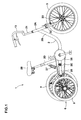
- FIG. 13 three-wheeled cycles having independent suspension wheels have been suggested as shown in Fig. 13 , (see, for example, Patent Document 1) .
- two rear wheels "a, a” are each provided with a suspension and move vertically independently of each other.
- the left rear wheel “a” is chain-driven to allow the rider to control the steering of a front wheel "b".
- the three-wheeled cycle allows the rider make a smooth turn by tilting the body of the cycle with the assistance of the individual suspensions.
- the tilting of the body of the cycle requires relatively soft suspensions.
- the soft suspensions work even when the cycle is not moving and may be felt as being wobbly by elderly riders who are losing their physical capabilities.
- the cushioning characteristics of the suspensions which work effectively when the bicycle is ridden on a rough road can be felt by elderly riders as unstable bouncing vibration.
- the left rear wheel "a" which is the drive wheel supports the right turn, thus allowing the rider to perform smooth cornering.
- the front wheel touches the road surface on the right side of the line extended from the drive wheel.
- the front wheel causes a force to act to prevent the left turn, thus failing to allow the rider to perform smooth cornering.
- the problem of not allowing the rider to perform smooth cornering in both right and left directions could be solved by providing a two-wheeldrive mechanism having a differentialgear. However, this would require a complex mechanism, having trouble with maintenance and increasing the production cost.
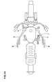
- the bicycle of Fig. 14 includes a spring means and a locking means.
- the spring means includes a U-shaped frame “f" and right and left arms “e, e".
- the U-shaped frame “f” has a horizontal shaft “d” pivoted to a mainframe.
- the right and left arms “e, e” are bent backward from both ends of the horizontal shaft “d” and have auxiliary wheels “g” at their ends.
- the spring means presses the auxiliary wheels "g” downward, and the locking means prevents the rotation of the frame "f".
- the front and rear wheels are used during normal riding, and when the bicycle is stopped or moving slowly, the locking means locks the vertical movement of the auxiliary wheels, thereby avoiding the bicycle from falling over.
- Patent Document 1 Japanese Patent Unexamined Publication No. 2000-335468
- Patent Document 2 Japanese Patent Unexamined Publication No. H1-136883
- the right and left auxiliary wheels “g, g” are pivoted to the ends of the arms “e, e" of the U-shaped frame “f” and move integrally vertically by the rotation of the U-shaped frame “f” pivoted to the mainframe of the bicycle. Therefore, when the right and left auxiliary wheels are on an uneven road surface, such as when the road has a lateral slope or when one auxiliary wheel runs onto a stepped portion, the height of the auxiliary wheels is fixed with only the higher one touching the road surface.
- the problem is that if the body of the bicycle tilts to the other side in this state, the other auxiliary wheel touches the road surface at a certain inclination, but then falls over due to an inertia force.
- Another problem of the bicycle with the auxiliary wheels is as follows.
- the rider makes a turn by tilting the body of the bicycle, if the auxiliary wheel "g" on the inside of the curve goes up by being pressed by the road surface, the other auxiliary wheel “g” also goes up and increases the resistance. This fails to allow the rider to achieve smooth movement.
- Yet another problem is as follows. When one auxiliary wheel “g” is in a certain position, the other auxiliary wheel “g” moving vertically may touch the rider's leg and hence disturb the pedaling. This problem could be solved by using not the swing arm type, but a direct driven type in which the auxiliary wheels "g” are vertically slid along a vertical support shaft. The direct driven type, however, would make the structure complicated, increasing the bicycle weight.
- the present invention basically includes a pair of arms rotatable independently of each other and a pair of arm lock means for restricting the rotation of the arms, thereby locking the vertical movement of the auxiliary wheels.
- the present invention has an obj ect of providing a bicycle that can be safely ridden by an elderly rider by allowing him/her to make a turn by tilting the body of the bicycle in the same manner as riding an ordinary bicycle, and that can be kept upright while stopped, regardless of the condition of the road surface.
- the bicycle includes: a frame extending longitudinally; a front wheel for steering at the front of the frame; a rear wheel at the rear of the frame; and an auxiliary means including first and second auxiliary support devices at one side and the other side, respectively, of the rear wheel, the first and second auxiliary support devices each including an auxiliary wheel for assisting movement of the bicycle, wherein each of the first and second auxiliary support devices includes: an arm whose one end is pivoted to the frame and whose free end moves vertically; the auxiliary wheel apart from and in parallel with the rear wheel, the auxiliary wheel being pivoted to the free end side of the arm; a biasing means for biasing the arm in the direction of lowering the auxiliary wheel; and an arm lock means for locking the rotation of the arm; the pair of arms rotate independently of each other; and the arm lock means restrict the rotation of the arms thereby locking the vertical movement of the auxiliary wheels.
- each of the arm lock means includes: a movable constrained plate rotating integral with the arm; and a locking means for locking the movable constrained plate by triggering operation of the arm lock lever provided in the frame, and the arm lock lever is triggered to lock the rotation of the movable constrained plates simultaneously by operating the locking means of the first and second auxiliary support devices.
- each of the arm lock means includes: an immovable constrained plate fixed to the frame; and a locking means on the free end side of the arm, the locking means sandwiching the immovable constrained plate by triggering operation of the arm lock lever, and the arm lock lever is triggered to lock the rotation of the arms simultaneously by operating the locking means of the first and second auxiliary support devices.
- the arm lock lever is attached to one end of a handlebar and a wheel brake lever is attached to the other end, the wheel brake lever operating wheel brake means for braking at least one of the front wheel and the rear wheel.
- each of the biasing means includes a spring means having a spring attached to the frame, the spring pressing the arm downward; and the spring means includes an adjusting means for adjusting the pressing force of the spring.
- the ratio (H1/H2) of the amount of downward movement H2 to the amount of upward movement H1 of the auxiliary wheels from the bottom surface of the rear wheel when the rear wheel is upright is 1.2 to 4.0
- the ratio (H1/D) of the amount of upward movement H1 to the diameter D of the rear wheel is 0.05 to 0.3.
- the auxiliary wheels disposed lateral to the rear wheel are pivoted to the free ends of the arms rotating while being downwardly biased by the biasing means. This allows the rider to lean to the right or the left by shifting his/her weight to the side. As a result, the rider can perform stable cornering with part of the load supported on the auxiliary wheels, thus traveling safely without being staggered.
- the auxiliary wheels can move vertically individually and run onto a projection such as pebbles on the road, allowing the rider to proceed without receiving a large impact.
- the arms of the auxiliary wheels disposed on both sides of the rear wheel rotate independently of each other, allowing the auxiliary wheels to individually perform the vertical movement. As a result, the rider can tilt the body of the bicycle by shifting his/her weight to the right or the left in the same manner as riding an ordinary bicycle not having auxiliary wheels.
- the arm lock means lock the vertical movement of the auxiliary wheels so as to fix the auxiliary wheels at desired heights even on a sloping road having a shoulder.
- the bicycle can be kept steadily upright without the rider having his/her feet on the road, preventing the rider from falling over even if hit by a strong cross wind.
- the auxiliary wheels can be moved vertically individually and be fixed at the individual heights as mentioned above. Therefore, when the road is uneven from one side of the rear wheel to the other, for example, when the road has a lateral slope or when one auxiliary wheel runs onto a stepped portion, the auxiliary wheels can be fixed at different heights from each other to keep the bicycle upright.
- a rider who does not have enough sense of balance can safely start moving the bicycle with the four wheels locked, and then can cancel the lock later.
- the rider can lock the auxiliary wheels at the heights corresponding to the slope so as to move safely while keeping the body of the bicycle by the four wheels, that is, the front, rear, and auxiliary wheels.
- the pair of arms can be restricted at the rotational positions independent of each other. This enables the auxiliary wheels on both sides of the rear wheel to come into contact with the road surface by fixing the auxiliary wheels at the individual heights corresponding to the road surface. This can be applied to the case of an undulating road surface besides a road with a uniform cross slope. As a result, the rider can safely stop the bicycle.
- the rear wheel disposed on the centerline as the main wheel supports the load on the rear portion of the bicycle stably. This prevents the body of the bicycle from largely bouncing due to the cushioning characteristics of the auxiliary wheels even on a rough road. Even if one auxiliary wheel falls into a ditch in the road, the rider can continue to move without being much influenced. Moreover, the rider can easily recognize the position of the rear wheel on the centerline, thereby easily steering the bicycle.
- the rider can ride the bicycle touching the ground with a total of four wheels of the front, rear, and auxiliary wheels which are disposed at both sides of the rear wheel and move vertically independently of each other.
- the rider can also stop the bicycle without touching the ground with his/her feet.
- the movable constrained plates of the arms are simultaneously locked when the rider triggers the arm lock lever.
- the auxiliary wheels easily fixed at appropriate heights with good operability as soon as the rider triggers the lever.
- the body of the bicycle can be kept in a stable posture by the rear and auxiliary wheels.
- the locking means sandwiching the immovable constrained plate is provided on the free end side of the arm so as to obtain a force of constraint proportional to the length of the arm. This makes it possible to obtain stable braking performance and also to reduce the size of the immovable constrained plate and hence the size of the arm lock means.
- the arm lock lever and the wheel brake lever are attached to both ends of the handlebar. This allows the rider to grip these levers to lock the arms with good operability and timing. Furthermore, the rider can safely stop the bicycle by gripping both levers at the ends of the handlebar simultaneously, thereby fixing the auxiliary wheels at the heights corresponding to the road surface. As a result, the bicycle can be kept in a stable posture by being supported by the locked auxiliary wheels.
- the arms are biased by the spring means including the adjusting means for adjusting the pressing force. Therefore, when the rider is losing his/her sense of balance, the spring can be adjusted hard to make the auxiliary wheels more supportive, thereby preventing the rider from falling over. In contrast, when the rider has a good sense of balance, the support of the auxiliary wheels can be adjusted less hard for the rider to ride with the body of the bicycle tilted in the same manner as riding an ordinary bicycle. Furthermore, when the rider tends to incline on either side, the spring on the inclined side can be adjusted hard to reduce the inclination of the body of the bicycle, thereby allowing the rider to ride safely. When the road slopes down to the left such as a shoulder, the spring on the left side can be adjusted hard to compensate the slope.
- the rider can make a turn by tilting the body of the bicycle, and the auxiliary wheels can be biased downward by a relatively compact mechanism.
- a bicycle 1 includes a frame 2 extending longitudinally to form the body of the bicycle, a front wheel 3 and a rear wheel 4 disposed respectively at the front and rear of the frame 2, and an auxiliary means 6 for supporting the body of the bicycle to enhance safety.
- the frame 2 of the present embodiment includes a head tube 2A, a down tube 2B extending backward from the head tube 2A, a seat tube 2D rising from the back of the down tube 2B so as to attach a height adjustable saddle 28 thereto, and a chain stay 2E extending backward from the rear end of the down tube 2B.
- the head tube 2A has the bottom end of a handle stem 21 and the top end of a steering column 22 inserted thereinto so as to rotatably support these ends.
- the steering column 22 is connected to the handle stem 21.
- the head tube 2A forms a steering gear together with a handlebar 13 attached to the top end of the handle stem 21, a fork 23 extending under the steering column 22, and the front wheel 3 axially supported at the bottom end of the fork 23.
- the chain stay 2E of the present embodiment is composed of a pair of outer frames 25, 25 whose rear end sides can move vertically by being axially supported at both ends of a horizontal shaft 24.
- the horizontal shaft 24 is supported through the rear end of the down tube 2B.
- the rear ends of the outer frames 25, 25 are connected via a hub shaft 26 by which the rear wheel 4 is axially supported.
- each outer frame 25 is provided at its rear end with a triangle frame 38 standing vertically.
- the chain stay 2E is connected to the seat tube 2D via a relatively hard suspension spring 27 extending therebetween to bias the rear wheel 4 downward.
- a driving gear 35 composed of a crankshaft 29, a chain ring 30, right and left cranks 32, a sprocket 33, and a chain 34.
- the crankshaft 29 is made immovable at the rear of the down tube 2B.
- the chain ring 30 is fixed to the crankshaft 29.
- the right and left cranks 32 rotate the chain ring 30 by pedals 31.
- the sprocket 33 is fixed to the hub shaft 26.
- the chain 34 extends between the sprocket 33 and the chain ring 30 so as to transmit the turning force of the chain ring 30 to the rear wheel 4.
- the force applied to the pedals 31 by the driving gear 35 is transmitted through the cranks 32, the chain ring 30, the chain 34, the sprocket 33, the hub shaft 26, and the rear wheel 4 in this order to reach the road surface, thereby moving the bicycle.
- the auxiliary means 6 is composed of first and second auxiliary support devices S1 and S2 including auxiliary wheels 5.
- the auxiliary wheels 5 are disposed outside the outer frames 25, 25 so as to assist the moving of the bicycle at both sides of the rear wheel 4.
- Each auxiliary support device S includes an arm 7 pivoted to the outer frame 25, an auxiliary wheel 5 pivoted to the outside of the free end of the arm 7, a biasing means 8 for biasing the arm 7, and an arm lock means 9 for locking the rotation of the arm 7.
- the arms 7 of the present embodiment are square bottle and their front ends are inserted into respective spindles 36.
- the spindles 36 protrude outwardly at a position to the rear of the outer frames 25 so that the free ends on the rear side can be supported to be vertically movable.
- the arms 7, 7 attached to the pair of the outer frames 25, 25 are not structurally linked to each other and rotate independently. At the free end of each arm 7 outwardly protrudes an auxiliary hub shaft 37.
- the auxiliary hub shaft 37 has a hub 40 of the auxiliary wheel 5 externally inserted around it via a bearing. This enables the auxiliary wheel 5 to be rotatably supported in parallel with the rear wheel 4 at the free end of the arm 7.
- the center of the auxiliary wheels 5 of the present embodiment are arranged a little behind the center of the rear wheel 4 disposed therebetween, but may alternatively be arranged just beside the center of the rear wheel 4 or a little ahead of the center of the rear wheel 4 within the limits of not disturbing the pedals 31.
- the pair of auxiliary wheels 5, 5 attached to the right and left arms 7, 7 can move vertically independently of each other at both sides of the rear wheel 4 in unison with the rotation of the arms 7.
- the pair of auxiliary wheels 5 have a spacing "W" shown in Fig. 4 which can be 250 to 600 mm and is preferably 300 to 400 mm. In the present embodiment, the spacing is set to 380 mm. When the spacing is less than 250 mm, the force to support the tilted body of the bicycle is inefficient, and in addition, the components including the arms 7 and the driving gear 35 have to be arranged within a narrow space, possibly causing trouble. In contrast, when the spacing exceeds 400 mm, the auxiliary wheels 5 protrude beyond the ordinary pedals 31. This may cause the auxiliary wheels 5 to hit things on the road and hence the rider to fall over. When the spacing exceeds 600 mm, which is wider than the ordinary handlebar 13, the auxiliary wheels 5 are highly likely to hit a telephone pole or the like, causing the rider to fall over.
- the auxiliary wheels 5 are preferably smaller than the rear wheel 4 and can be 3 to 20 inches.
- the auxiliary wheels 5 of the present embodiment are formed of spoke wheels equipped with air rubber tires, but may alternatively be nylon wheels, urethane wheels, or the like equipped with solid rubber tires or urethane tires.
- the biasing means 8 bias the arms 7 in the direction of lowering the auxiliary wheels 5, and in the present embodiment, are formed of spring means 17.
- the spring means 17 includes a telescopic shaft 39 and a spring 16.
- the telescopic shaft 39 is expandable and contractable by an outer cylinder and a core slidably inserted into the outer cylinder.
- the telescopic shaft 39 is axially supported at its top and bottom ends between the top end of the triangle frame 38 of the outer frame 25 and the intermediate position of the arm 7.
- the spring 16 is formed of a coil spring 16A externally inserted around the telescopic shaft 39. The elastic force of the spring 16 presses the auxiliary wheel 5 at the end of the arm 7 downward.
- the auxiliary wheels 5 on both sides of the rear wheel 4 are pivoted to the ends of the arms 7 vertically moving while being pressed downward by the spring force. Therefore, when the rider shifts his/her weight to the right or the left, as shown in Fig. 7 , the auxiliary wheel 5 on the inside of the curve opposes the spring force and is pressed up along the road surface, allowing the rider to lean his/her body. As a result, the rider can perform stable cornering without skidding, with part of the load supported on the auxiliary wheel 5 pressing the road surface by its spring force.
- the auxiliary wheels 5 can move vertically individually and easily run onto a projection 50 such as pebbles on the road, allowing the rider to proceed without receiving a large impact.
- the arms 7 equipped with the auxiliary wheels 5 rotate independently of each other on both sides of the rear wheel 4, so that the right and left auxiliary wheels 5, 5 can move vertically individually.
- the rider can tilt the body of the bicycle by shifting his/her weight in the same manner as riding an ordinary bicycle not having auxiliary wheels 5, thereby riding comfortably.
- the rear wheel 4 disposed on the centerline as the main wheel supports the load on the rear portion of the bicycle stably by being supported by the auxiliary wheels 5 pressing the road surface by its spring force.
- the coil springs 16A have a spring constant which can be 5 to 30 N/mm, and is preferably 7 to 15 N/mm. In the present embodiment, the spring constant is set to 10 N/mm.
- the spring constant is less than 5 N/mm, the force to press the auxiliary wheels 5 against the road surface is insufficient, causing the auxiliary wheels 5 received impact from a rough road surface to bounce.
- the spring constant exceeds 30 N/mm, the spring is too hard for the rider to lean to the right or the left, possibly causing the rider to be swung from side to side on a rough road surface.
- the spring means 17 of the present embodiment includes an adjusting means 18 consisting of a screw portion 41 and a double nut 42.
- the screw portion 41 has a screw groove on the top end of the telescopic shaft 39.
- the double nut 42 is threaded to the screw portion 41 so as to adjust the length of the coil spring 16A.
- the adjusting means 18 can increase or decrease the pressing force of the auxiliary wheel 5. For example, when the rider is losing his/her sense of balance, the coil spring 16A can be compressed to make the auxiliary wheels 5 more supportive, thereby preventing the rider from falling over.
- the coil spring 16A can be soft enough for the rider to enjoy slaloming by largely tilting the body of the bicycle in the same manner as riding an ordinary bicycle. Furthermore, when the rider tends to incline on either side, the coil spring 16A on the inclined side can be hardened to reduce the inclination of the body of the bicycle, thereby allowing the rider to ride safely. When the road slopes down to the left such as a shoulder, the coil spring 16A on the left side can be hardened to compensate the slope.
- the rotation range of the arms 7 is determined by the length and other conditions of the coil springs 16A.
- the range of vertical movement of the auxiliary wheels 5 is determined by the rotation range and length of the arms 7.
- the ratio (H1/H2) of the amount of downward movement H2 to the amount of upward movement H1 of the auxiliary wheels 5 from the bottom surface of the rear wheel 4 when the rear wheel 4 is upright can be 1.2 to 4.0, and is preferably 2.0 to 3.5.
- the ratio is set to 2.8 (H1 is 70 mm and H2 is 25 mm).
- H1 is 70 mm
- H2 is 25 mm.
- the ratio exceeds 4.0, the upward movement exceeds the maximum lean angle. This requires very large coil springs 16A, thereby increasing the size and cost of the spring means 17.
- the ratio (H1/D) of the amount of upward movement H1 to the diameter D of the rear wheel 4 can be 0. 05 to 0.3, and is preferably 0. 1 to 0.2. In the present embodiment, the ratio is set to 0.13. When the ratio is less than 0.05, the lean angle is not enough to perform cornering. In contrast, when it exceeds 0.3, the auxiliary wheels 5 have a very high elevation speed, requiring making the spring means 17 very large.
- the biasing means 8 are formed of the coil springs 16A, but may alternatively be formed of metal springs such as torsion springs, spiral springs, laminated springs, or disc springs; fluid springs such as air springs or liquid springs; rubber springs; synthetic resin springs; or the like.
- the arm lock means 9 of the present embodiment are formed on the arms 7, 7 and include movable constrained plates 10 and locking means 12 as shown in Figs. 3 and 5 .
- Each of the movable constrained plates 10 is formed of a disc rotor 10A rotating around the spindle 36 integrally with the arm 7.
- Each of the locking means 12 locks the rotation of the disc rotor 10A.
- the locking means 12 of the present embodiment is formed of a caliper 12A and includes a pad (unillustrated). The pad is attached to the outer surface of the outer frame 25 of the chain stay 2E so as to frictionally fix the disc rotor 10A by sandwiching and pressing it from both sides. These pads press the disc rotors 10A when the rider triggers an arm lock lever 11 engaged therewith via the wire 43 as shown in Fig. 2 .
- the arm lock lever 11 locks the disc rotors 10A to restrict the rotation of the arms 7, thereby fixing the auxiliary wheels 5 at those heights.
- This allows the bicycle to be kept steadily upright without the rider having his/her feet on the road, thereby preventing the rider from falling over even if hit by a strong cross wind.
- the auxiliary wheels 5 can be moved vertically individually and be fixed at the individual heights.
- the auxiliary wheels 5 fixed at the different heights can stably support the body of the bicycle.
- the elderly rider who is losing his/her sense of balance can safely start moving the bicycle with the four wheels locked, and later release the arm lock lever 11 to cancel the lock.
- the rider can lock the auxiliary wheels 5 at the heights corresponding to the slope so as to move safely while keeping the body of the bicycle by the four wheels, that is, the front, rear, and auxiliary wheels.
- the rider can also safely stop the bicycle as follows. The rider can grasp the arm lock lever 11 softly enough to produce a frictional force which allows the wheels to rotate slowly while being braked by the disc rotors 10A.
- the arm lock means 9 in the present embodiment are formed of the disc rotors 10A, but may be modified variously.
- the movable constrained plates 10 may be disposed at a position to the free ends of the arms 7 and sandwiched between the halves of each caliper 12A so that the vertical movement of the arms 7 can be firmly locked by a relatively small force.
- the arm lock lever 11 of the present embodiment is attached to a right grip 44 of the handlebar 13.
- the arm lock lever 11 includes a gripping portion 47 and a double engaging portion 49 at the end of the gripping portion 47 .
- the engaging portion 49 is connected to the ends of two abutting wires 43, 43 extending toward the right and left locking means 12, 12.
- the disc rotors 10A, 10A are locked to lock the vertical movement of the right and left auxiliary wheels 5, 5 simultaneously.
- the auxiliary wheels 5 can be easily fixed at appropriate heights as soon as the rider grips the gripping portion 47 with his/her right hand with good operability. This allows the rear wheel 4 and the auxiliary wheels 5 to hold the body of the bicycle in a stable posture.
- the handlebar 13 has a left grip 46 and a wheel brake lever 15 attached thereto.
- the wheel brake lever 15 is connected with the ends of the wires 45, 45 extending from a caliper brake 14A and a drum brake 14B, respectively.
- the caliper brake 14A brakes the front wheel 3 and the drum brake 14B brakes the rear wheel 4.
- the wheel brake lever 15 is formed of the same lever part as the arm lock lever 11 and includes a double engaging portion 49 for fixing the ends of the wires 45, 45 side by side.
- the rider can operate the front and rear wheel brake means 14 consisting of the caliper brake 14A and the drum brake 14B simultaneously by gripping the gripping portion 47.
- the wire 45 extending to the caliper brake 14A of the front wheel 3 is attached with a power modulator 48 for delaying the transmission of the operation of the brake lever. This makes the action of the drum brake 14B of the rear wheel 4 precede the action of the caliper brake 14A, thereby balancing the braking effect between the front and rear wheels.
- the wheel brake lever 15 and the arm lock lever 11 are attached to the right and left grips 44, 46, respectively, of the handlebar 13, thereby facilitating the rider to use these levers properly.
- the rider can grip both levers simultaneously, thereby fixing the auxiliary wheels 5 at the heights corresponding to the road surface.
- the bicycle After being stopped, the bicycle can be kept in a stable posture by being supported by the locked auxiliary wheels 5. Therefore, even the rider who is not quick in action can easily respond to an unexpected event, thereby preventing from falling over and suffering injuries.
- the arm lock means 9 of the present embodiment each include an immovable constrained plate 19 fixed to the rear end of the chain stay 2E of the frame 2 and a locking means 12 provided on the free end side of the arm 7.
- the immovable constrained plate 19 spreads out in a fan-like formaround its front side.
- the immovable constrained plate 19 includes a fitting piece 19A, an arc portion 19B, and upper and lower inclined pieces 19U and 19D integrated to form a fan-shaped frame whose central portion is open for weight saving.
- the fitting piece 19A which is disposed on the front side of the immovable constrained plate 19, is vertically long and has an L-shaped cross section.
- the arc portion 19B is disposed on the rear side of the immovable constrained plate 19 so as to face the fitting piece 19A.
- the upper and lower inclined pieces 19U and 19D connect the top and bottom ends of the arc portion 19B and the top and bottom ends of the fitting piece 19A, respectively.
- the fitting piece 19A is bolted to the rear end surface of the chain stay 2E so that the immovable constrained plate 19 is formed behind the chain stay 2E.
- the locking means 12 is formed of the caliper 12A in the same manner as in the first embodiment.
- the caliper 12A is fixed to the inner surface of an upright attachment plate 51 expending backward and whose front end is buried in the free end of the arm 7.
- the caliper 12A is externally inserted around the arc portion 19B of the immovable constrained plate 19 and moves vertically along the arc portion 19B with the rotation of the arm 7 as shown in Fig. 12 .
- the halves of the caliper 12A sandwich the arc portion 19B to move the right and left locking means 12, 12 simultaneously, thereby locking the rotation of the individual arms 7, 7.
- the locking means 12 provided on the free end side of the arm 7 sandwiches the immovable constrained plate 19 so as to lock the rotation of the arms 7.
- This produces a large force of constraint proportional to the length of the arm 7.
- auxiliary support device S including the auxiliary wheels 5, the arms 7 for supporting the auxiliary wheels 5, the spring means 17 for biasing the arms 7, the arm lock means 9, and the frames (the triangle frames 38).
- the assembly part can be designed to be bolted to an ordinary bicycle so as to be attached as optional equipment to all kinds of bicycles including mountain bikes.
- the assembly part can be conveniently utilized by being added to existing bicycles or detached therefrom depending on the situation. It is also possible to use an auxiliary support device S which can tilt the arm 7 upward against the spring force.
- the arm 7 extends laterally and is pivoted to the frame 2 around its inner end and axially supports the auxiliary wheels 5 by its external end. As the auxiliary wheels 5 go higher, the contact with the road surface is expanded outward. This can increase the stability when the bicycle is tilted.
Landscapes
- Engineering & Computer Science (AREA)
- Mechanical Engineering (AREA)
- Automatic Cycles, And Cycles In General (AREA)
- Steering Devices For Bicycles And Motorcycles (AREA)
- Handcart (AREA)
- Motorcycle And Bicycle Frame (AREA)
Applications Claiming Priority (3)
| Application Number | Priority Date | Filing Date | Title |
|---|---|---|---|
| JP2005314978 | 2005-10-28 | ||
| JP2006284228A JP4374367B2 (ja) | 2005-10-28 | 2006-10-18 | 自転車 |
| PCT/JP2006/321520 WO2007049753A1 (fr) | 2005-10-28 | 2006-10-27 | Bicyclette |
Publications (2)
| Publication Number | Publication Date |
|---|---|
| EP1942048A1 true EP1942048A1 (fr) | 2008-07-09 |
| EP1942048A4 EP1942048A4 (fr) | 2010-10-13 |
Family
ID=37967861
Family Applications (1)
| Application Number | Title | Priority Date | Filing Date |
|---|---|---|---|
| EP06822481A Withdrawn EP1942048A4 (fr) | 2005-10-28 | 2006-10-27 | Bicyclette |
Country Status (5)
| Country | Link |
|---|---|
| US (1) | US7798512B2 (fr) |
| EP (1) | EP1942048A4 (fr) |
| JP (1) | JP4374367B2 (fr) |
| CN (1) | CN101316756B (fr) |
| WO (1) | WO2007049753A1 (fr) |
Families Citing this family (21)
| Publication number | Priority date | Publication date | Assignee | Title |
|---|---|---|---|---|
| TWI291424B (en) * | 2006-07-03 | 2007-12-21 | Joy Ride Technology Co Ltd | Vehicle with adjustable distance between moving/carrying units |
| DE102007019026A1 (de) * | 2006-10-30 | 2008-10-23 | Steinhilber, Hektor | Fahrzeug mit drei Rädern |
| JP4681016B2 (ja) * | 2008-03-10 | 2011-05-11 | 株式会社豊田中央研究所 | 倒立振子型車輪移動体 |
| JP2009248694A (ja) * | 2008-04-04 | 2009-10-29 | Kawamura Cycle:Kk | 自転車 |
| JP4587335B2 (ja) * | 2008-04-04 | 2010-11-24 | 株式会社ユニコンセプト | 自転車の横転防止装置 |
| JP2009286145A (ja) * | 2008-05-27 | 2009-12-10 | Kawamura Cycle:Kk | 自転車 |
| JP2009286314A (ja) * | 2008-05-30 | 2009-12-10 | Kawamura Cycle:Kk | 自転車 |
| CN102317144B (zh) * | 2009-02-16 | 2013-06-12 | 稼农公也 | 多轮式车辆 |
| JP5246628B2 (ja) * | 2009-11-19 | 2013-07-24 | 益敏 青山 | 二輪車用ストラット |
| JP5572396B2 (ja) * | 2010-01-06 | 2014-08-13 | 株式会社カワムラサイクル | 伸縮器並びにそれを用いた伸縮装置及び自転車 |
| US20130078028A1 (en) * | 2011-09-23 | 2013-03-28 | Yu-Gang Chen | Connecting mechanism |
| KR101319481B1 (ko) * | 2012-04-12 | 2013-10-17 | 김정근 | 자전거 프레임 및 이를 이용한 이륜 및 삼륜 변환이 가능한 자전거 |
| CN103318293B (zh) * | 2013-05-09 | 2016-01-13 | 浙江理工大学 | 一种残疾人自行车 |
| US9067633B2 (en) * | 2013-06-12 | 2015-06-30 | Robert Bell | Bicycle convertible to a stroller |
| JP6055392B2 (ja) * | 2013-10-25 | 2016-12-27 | 本田技研工業株式会社 | 倒立振子制御型移動体 |
| KR101533932B1 (ko) * | 2014-07-15 | 2015-07-03 | 김용욱 | 회전 주행의 안정성이 향상된 이륜차 |
| JP6147307B2 (ja) * | 2015-09-18 | 2017-06-14 | 本田技研工業株式会社 | 車両のサスペンションロック機構 |
| US9440488B1 (en) | 2016-02-08 | 2016-09-13 | Ahmed Y. A. Mothafar | Hubless wheel system for motor vehicles |
| JP6784427B1 (ja) * | 2019-12-20 | 2020-11-11 | 株式会社トラストコーポレーション | 二輪車の補助輪機構 |
| JP7373989B2 (ja) * | 2019-12-26 | 2023-11-06 | カワサキモータース株式会社 | リーン型車両 |
| CN113911255B (zh) * | 2021-10-30 | 2023-10-24 | 赫星(厦门)电子有限公司 | 一种智能自行车助力装置 |
Citations (7)
| Publication number | Priority date | Publication date | Assignee | Title |
|---|---|---|---|---|
| GB181742A (en) * | 1921-06-17 | 1922-12-14 | Atlantic Ag Fuer Automobilbau | Improvements in and relating to power driven vehicles |
| GB283429A (en) * | 1927-07-27 | 1928-01-12 | George Alfred Nisbet | Improvements in or relating to safety wheels or supports for cycles |
| US5100163A (en) * | 1991-02-04 | 1992-03-31 | Egley Larry P | Adjustable training wheel apparatus |
| US5352403A (en) * | 1993-10-01 | 1994-10-04 | Egley Larry P | Adjustable training wheel apparatus |
| CN2250893Y (zh) * | 1996-05-24 | 1997-04-02 | 董恩元 | 手控自行车支架轮 |
| CN2296843Y (zh) * | 1997-07-16 | 1998-11-11 | 田延生 | 保持骑车人平衡的收放支撑梯 |
| JP2003019987A (ja) * | 2001-07-06 | 2003-01-21 | Hitoshi Noda | 自転車の補助車輪構造 |
Family Cites Families (16)
| Publication number | Priority date | Publication date | Assignee | Title |
|---|---|---|---|---|
| USRE18424E (en) * | 1932-04-12 | Fornia | ||
| US1403249A (en) * | 1920-01-05 | 1922-01-10 | Frederick A Johanknecht | Motor vnbicle |
| US3465840A (en) * | 1967-03-14 | 1969-09-09 | Thomas O Summers | Gyro stabilized center tracking vehicle |
| US3700059A (en) * | 1971-06-11 | 1972-10-24 | Denver Sutton | Tandem wheeled vehicle with stabilizing apparatus |
| JPS5140192Y2 (fr) * | 1972-07-06 | 1976-10-01 | ||
| US3916195A (en) | 1974-06-17 | 1975-10-28 | Philco Ford Corp | Non-dispersive multiple gas analyzer |
| FR2526745A1 (fr) * | 1982-05-12 | 1983-11-18 | Motobecane Ateliers | Vehicule motorise du type comprenant quatre roues dont deux laterales stabilisatrices sont blocables a volonte |
| JPS59185183U (ja) | 1983-05-28 | 1984-12-08 | 土江 公裕 | 二輪車の補助車輪装置 |
| US4826194A (en) | 1987-10-26 | 1989-05-02 | Masami Sakita | Two-wheel vehicle with auxiliary support system |
| JPH02237878A (ja) | 1989-03-11 | 1990-09-20 | Yoshiyuki Hayashi | 自転車を安定させる補助車輪 |
| CN2070708U (zh) * | 1990-02-12 | 1991-02-06 | 熊来利 | 自行车座凳高低变换装置 |
| JP2000168648A (ja) | 1998-12-04 | 2000-06-20 | Kaizo Maeda | 離着地自在な自転車補助車輪 |
| JP2000335468A (ja) | 1999-05-28 | 2000-12-05 | Bridgestone Cycle Co | 三輪車 |
| JP3300925B2 (ja) * | 1999-11-24 | 2002-07-08 | 博 吉田 | 傾き機能付き補助輪支持腕 |
| JP2001315677A (ja) | 2000-05-11 | 2001-11-13 | Kayaba Ind Co Ltd | 自動二輪車用補助車輪支持装置 |
| WO2004014716A1 (fr) | 2002-08-09 | 2004-02-19 | Peraves Aktiengesellschaft | Systeme pour stabiliser un vehicule a voie unique et vehicule a voie unique equipe d'un tel systeme |
-
2006
- 2006-10-18 JP JP2006284228A patent/JP4374367B2/ja not_active Expired - Fee Related
- 2006-10-27 EP EP06822481A patent/EP1942048A4/fr not_active Withdrawn
- 2006-10-27 CN CN2006800398258A patent/CN101316756B/zh not_active Expired - Fee Related
- 2006-10-27 US US12/084,109 patent/US7798512B2/en not_active Expired - Fee Related
- 2006-10-27 WO PCT/JP2006/321520 patent/WO2007049753A1/fr active Application Filing
Patent Citations (7)
| Publication number | Priority date | Publication date | Assignee | Title |
|---|---|---|---|---|
| GB181742A (en) * | 1921-06-17 | 1922-12-14 | Atlantic Ag Fuer Automobilbau | Improvements in and relating to power driven vehicles |
| GB283429A (en) * | 1927-07-27 | 1928-01-12 | George Alfred Nisbet | Improvements in or relating to safety wheels or supports for cycles |
| US5100163A (en) * | 1991-02-04 | 1992-03-31 | Egley Larry P | Adjustable training wheel apparatus |
| US5352403A (en) * | 1993-10-01 | 1994-10-04 | Egley Larry P | Adjustable training wheel apparatus |
| CN2250893Y (zh) * | 1996-05-24 | 1997-04-02 | 董恩元 | 手控自行车支架轮 |
| CN2296843Y (zh) * | 1997-07-16 | 1998-11-11 | 田延生 | 保持骑车人平衡的收放支撑梯 |
| JP2003019987A (ja) * | 2001-07-06 | 2003-01-21 | Hitoshi Noda | 自転車の補助車輪構造 |
Non-Patent Citations (1)
| Title |
|---|
| See also references of WO2007049753A1 * |
Also Published As
| Publication number | Publication date |
|---|---|
| WO2007049753A1 (fr) | 2007-05-03 |
| JP4374367B2 (ja) | 2009-12-02 |
| CN101316756B (zh) | 2011-08-24 |
| CN101316756A (zh) | 2008-12-03 |
| US7798512B2 (en) | 2010-09-21 |
| JP2007145318A (ja) | 2007-06-14 |
| US20080258426A1 (en) | 2008-10-23 |
| EP1942048A4 (fr) | 2010-10-13 |
Similar Documents
| Publication | Publication Date | Title |
|---|---|---|
| US7798512B2 (en) | Bicycle | |
| JP2529619B2 (ja) | 自転車用安定化装置 | |
| JP4694508B2 (ja) | マルチトラック・カーブ傾斜乗り物と乗り物を傾斜させる方法 | |
| US4925203A (en) | Semi-recumbent bicycle with adjustable frame | |
| US20160368559A1 (en) | Vehicle Terrain-Tracking Systems | |
| EP1635756B1 (fr) | Vehicule d'aide a la mobilite | |
| US20100237582A1 (en) | Folding recumbent vehicle | |
| JP2010508188A (ja) | 三輪車 | |
| US20090085320A1 (en) | Cycle Having Unique Balancing Capabilities | |
| TW201713544A (zh) | 自行車車架 | |
| CA2847485C (fr) | Vehicule a position couchee | |
| JP2003081165A (ja) | 前二輪式三輪車 | |
| US9155932B1 (en) | Bicycle with resistance arm exercise | |
| JP2010149828A (ja) | 三輪自転車 | |
| WO2007057992A1 (fr) | Bicyclette | |
| TWI755600B (zh) | 自平衡車 | |
| JP2004168072A (ja) | 前二輪三輪車とそれに用いるフロントフレーム | |
| KR200395054Y1 (ko) | 보드형 삼륜 자전거 | |
| JP2006151032A (ja) | 立ち乗り式小型車両 | |
| JP2006056493A (ja) | 前二輪自転車 | |
| JP7042534B1 (ja) | 自転車 | |
| JP7357419B1 (ja) | スイング機能付き車両 | |
| EP4281355A1 (fr) | Véhicule, en particulier du type cyclisme, plus particulièrement sous la forme d'une bicyclette | |
| KR20100040707A (ko) | 손 발페달에 의한 전 후륜 동시구동형 자전거 | |
| JPH0195986A (ja) | 3点支持車輌 |
Legal Events
| Date | Code | Title | Description |
|---|---|---|---|
| PUAI | Public reference made under article 153(3) epc to a published international application that has entered the european phase |
Free format text: ORIGINAL CODE: 0009012 |
|
| 17P | Request for examination filed |
Effective date: 20080430 |
|
| AK | Designated contracting states |
Kind code of ref document: A1 Designated state(s): CH DE FR GB IT LI NL |
|
| DAX | Request for extension of the european patent (deleted) | ||
| RBV | Designated contracting states (corrected) |
Designated state(s): CH DE FR GB IT LI NL |
|
| A4 | Supplementary search report drawn up and despatched |
Effective date: 20100913 |
|
| STAA | Information on the status of an ep patent application or granted ep patent |
Free format text: STATUS: THE APPLICATION IS DEEMED TO BE WITHDRAWN |
|
| 18D | Application deemed to be withdrawn |
Effective date: 20110410 |