EP1937429B1 - Verfahren und vorrichtung zum stranggiessen - Google Patents
Verfahren und vorrichtung zum stranggiessen Download PDFInfo
- Publication number
- EP1937429B1 EP1937429B1 EP06841185A EP06841185A EP1937429B1 EP 1937429 B1 EP1937429 B1 EP 1937429B1 EP 06841185 A EP06841185 A EP 06841185A EP 06841185 A EP06841185 A EP 06841185A EP 1937429 B1 EP1937429 B1 EP 1937429B1
- Authority
- EP
- European Patent Office
- Prior art keywords
- cooling
- metal strip
- section
- continuous casting
- strip
- Prior art date
- Legal status (The legal status is an assumption and is not a legal conclusion. Google has not performed a legal analysis and makes no representation as to the accuracy of the status listed.)
- Active
Links
- 238000000034 method Methods 0.000 title claims abstract description 26
- 238000009749 continuous casting Methods 0.000 title claims abstract description 24
- 238000001816 cooling Methods 0.000 claims abstract description 100
- 229910052751 metal Inorganic materials 0.000 claims abstract description 92
- 239000002184 metal Substances 0.000 claims abstract description 92
- 238000010438 heat treatment Methods 0.000 claims abstract description 4
- 238000005096 rolling process Methods 0.000 claims abstract description 4
- 238000005452 bending Methods 0.000 claims description 11
- 239000012809 cooling fluid Substances 0.000 claims description 6
- 229910001338 liquidmetal Inorganic materials 0.000 claims description 5
- 239000002826 coolant Substances 0.000 abstract description 31
- 239000007788 liquid Substances 0.000 abstract description 3
- 230000009466 transformation Effects 0.000 abstract description 3
- 238000000844 transformation Methods 0.000 abstract 1
- 230000000694 effects Effects 0.000 description 11
- 239000007921 spray Substances 0.000 description 8
- XLYOFNOQVPJJNP-UHFFFAOYSA-N water Substances O XLYOFNOQVPJJNP-UHFFFAOYSA-N 0.000 description 8
- 229910001566 austenite Inorganic materials 0.000 description 4
- 238000005266 casting Methods 0.000 description 4
- 238000005336 cracking Methods 0.000 description 4
- 238000006243 chemical reaction Methods 0.000 description 3
- 238000004140 cleaning Methods 0.000 description 3
- 239000000498 cooling water Substances 0.000 description 3
- 238000009826 distribution Methods 0.000 description 3
- 239000000463 material Substances 0.000 description 3
- 238000003303 reheating Methods 0.000 description 3
- 230000035939 shock Effects 0.000 description 3
- 238000007711 solidification Methods 0.000 description 3
- 230000008023 solidification Effects 0.000 description 3
- 229910000859 α-Fe Inorganic materials 0.000 description 3
- RYGMFSIKBFXOCR-UHFFFAOYSA-N Copper Chemical compound [Cu] RYGMFSIKBFXOCR-UHFFFAOYSA-N 0.000 description 2
- 229910000831 Steel Inorganic materials 0.000 description 2
- 229910052782 aluminium Inorganic materials 0.000 description 2
- -1 aluminum nitrides Chemical class 0.000 description 2
- 229910052802 copper Inorganic materials 0.000 description 2
- 239000010949 copper Substances 0.000 description 2
- 230000001419 dependent effect Effects 0.000 description 2
- 230000029142 excretion Effects 0.000 description 2
- 229910000734 martensite Inorganic materials 0.000 description 2
- 238000007670 refining Methods 0.000 description 2
- 239000010959 steel Substances 0.000 description 2
- 229910000975 Carbon steel Inorganic materials 0.000 description 1
- 238000009825 accumulation Methods 0.000 description 1
- 230000002411 adverse Effects 0.000 description 1
- 230000015572 biosynthetic process Effects 0.000 description 1
- 238000010276 construction Methods 0.000 description 1
- 230000006378 damage Effects 0.000 description 1
- 238000006073 displacement reaction Methods 0.000 description 1
- 238000005516 engineering process Methods 0.000 description 1
- 230000003628 erosive effect Effects 0.000 description 1
- 238000000605 extraction Methods 0.000 description 1
- 210000003608 fece Anatomy 0.000 description 1
- 239000012530 fluid Substances 0.000 description 1
- 239000007769 metal material Substances 0.000 description 1
- 239000000203 mixture Substances 0.000 description 1
- 239000002244 precipitate Substances 0.000 description 1
- 239000007858 starting material Substances 0.000 description 1
- 239000000126 substance Substances 0.000 description 1
Images


Classifications
-
- B—PERFORMING OPERATIONS; TRANSPORTING
- B22—CASTING; POWDER METALLURGY
- B22D—CASTING OF METALS; CASTING OF OTHER SUBSTANCES BY THE SAME PROCESSES OR DEVICES
- B22D11/00—Continuous casting of metals, i.e. casting in indefinite lengths
- B22D11/12—Accessories for subsequent treating or working cast stock in situ
- B22D11/124—Accessories for subsequent treating or working cast stock in situ for cooling
-
- B—PERFORMING OPERATIONS; TRANSPORTING
- B22—CASTING; POWDER METALLURGY
- B22D—CASTING OF METALS; CASTING OF OTHER SUBSTANCES BY THE SAME PROCESSES OR DEVICES
- B22D11/00—Continuous casting of metals, i.e. casting in indefinite lengths
- B22D11/16—Controlling or regulating processes or operations
- B22D11/22—Controlling or regulating processes or operations for cooling cast stock or mould
- B22D11/225—Controlling or regulating processes or operations for cooling cast stock or mould for secondary cooling
-
- B—PERFORMING OPERATIONS; TRANSPORTING
- B22—CASTING; POWDER METALLURGY
- B22D—CASTING OF METALS; CASTING OF OTHER SUBSTANCES BY THE SAME PROCESSES OR DEVICES
- B22D11/00—Continuous casting of metals, i.e. casting in indefinite lengths
- B22D11/14—Plants for continuous casting
- B22D11/141—Plants for continuous casting for vertical casting
Definitions
- the invention relates to a method for the continuous casting of slab, Dünnbrammen-, Vorblock-, Vorprofil-, Rundprofil-, Rohrprofil- or billet strands and the like of liquid metal in a continuous casting, in which metal emerges from a mold vertically downwards, wherein the metal strip then vertically downwardly guided along a vertical strand guide and thereby cooled, wherein the metal strip is then bent from the vertical direction in the horizontal direction and wherein in the end region of the bend in the horizontal direction or after the bend in the horizontal direction, a mechanical deformation of the metal strip he follows. Furthermore, the invention relates to a continuous casting plant, in particular for carrying out this method.
- a generic method for continuous casting is for example from the EP 1 108 485 A1 or from the WO 2004/048016 A2 known.
- liquid metal in particular steel
- a mold wherein it solidifies and forms a metal band which is gradually diverted or bent from the vertical direction into the horizontal direction.
- a vertical strand guide which initially leads the still very hot metal strip vertically below.
- the metal strip is gradually bent by appropriate rollers or rollers in the horizontal.
- the EP 1 108 485 A1 proposes for this purpose a device for cooling the cast strand in a cooling zone, in which the strand by means of pairs of rollers which are arranged transversely to the strand axis along the strand withdrawal direction one above the other, supported, wherein the application of coolant further cools the strand.
- the proposed device comprises a coolant-conveying coolant element arranged between two rollers lying one on top of the other, which extends along the longitudinal axis of the rollers and is designed such that gaps are created between the respective cooling element and the roller and the cooling element and the strand. wherein the respective cooling element is provided with at least one coolant-conveying, opening into a gap channel.
- the WO 2004/048016 A2 provides for optimal temperature control of the cast metal strip, which is determined by the outlet temperature, which is determined by controlling the surface temperature at the end of the metallurgical strand length of the cast strand, a dynamic spray system in the form of water volume distribution and pressure distribution or impulse distribution over the strand width and strand length functional to a is controlled for the strand length and the strand width calculated temperature profile curve.
- the invention is therefore based on the object niezuentwickein a method of the type mentioned above and a corresponding device such that it is possible, in addition to optimal cooling of the metal strip also to achieve that the scaling of the strip surface is minimized.
- the solution of this problem by the invention according to the method is achieved in that in the conveying direction of the metal strip behind the mold and before the mechanical deformation of the metal strip in a first section, a cooling of the metal strip with a heat transfer coefficient between 3,000 and 10,000 W / (m 2 K) , In the conveying direction after cooling in a second section by heat balance in the metal strip with or without reduced cooling of the surface of the metal strip, the surface of the metal strip is heated to a temperature Ac3 or Ar3, after which the mechanical deformation takes place in a third section.
- the surfaces of the metal strip are cleaned before being exposed to the cooling medium for cooling, the effect of subsequent cooling can be further improved.
- the cleaning can be done by descaling, for example, by the fact that in strand or metal strip extraction direction opposite each other, first reached by the metal strip / strand and thus foremost or topmost coolant (nozzles, nozzle bar od. Like.)
- the cooling medium under high pressure Apply so that a descaling results.
- the mechanical deformation in the third section can be a straightening process of the metal strip or include such a process. Alternatively or additionally, it may be provided that the mechanical deformation in the third section is a rolling process of the metal strip or comprises such a process.
- the cooling in the first section can be limited to the region of the vertical strand guide, designed as intensive cooling.
- the term of the vertical strand guide should also include that the metal strip is guided largely vertically.
- the cooling in the first section can also take place intermittently, wherein the metal strip / strand is alternately intensively and weakly cooled, for example by changing thedemediumbeaufschlagungsêt [I: min: m 2 ] and / or setting different distances of the coolant to the metal strip.
- the proposed continuous casting for continuous casting of slabs, Dünnbrammen-, Vorblock-, Vorprofil-, Rundprofil-, Rohrprofil- or billet strands and the like of liquid metal, with a mold, from which the metal exits vertically downwards, a below the mold arranged vertical Strand guide and means for bending the metal strip from the vertical direction in the horizontal direction, wherein mechanical Umformkar for the metal strip are arranged in the end region of the bend in the horizontal direction or after the bend in the horizontal direction, according to the invention is characterized in that the vertical Strand guide has a number in the conveying direction of the metal strip disposed on both sides of the metal strip rollers, wherein in the region of the rollers first cooling means are arranged, with which a cooling fluid can be applied to the surface of the metal strip, wherein the cooling means in vertical and / or horizontal R ichtung are arranged displaceably and wherein additional second Coolant are arranged stationary in the vertical strand guide
- the coolant can advantageously be designed to be oscillatable.
- the first and / or the second coolant may have a housing, from which the cooling fluid is applied by means of at least one nozzle.
- the cooling fluid can be applied from the housing by means of two nozzles or rows of nozzles.
- a cooling with a defined intensity which is chosen so that on the one hand a high-quality metal strip can be produced, which has the desired microstructure and microstructure composition, but on the other hand also the degree of scaling of the strip surface minimal can be held.
- the proposal also reduces the accumulation of undesirable side effects on the strip surface.
- the proposed method reduces the risk of excretions or so-called "hot shortness", so that advantages are also achieved in this regard. Due to the lowering of the surface temperature required for the thermal shock - this should not be lower than the martensite start temperature - the austenite in the metal strip is converted into ferrite with a grain refining. In the subsequent reheating due to the large temperature gradient between the strand surface and the core of the metal strip, a re-conversion of the fine ferrite into austenite with small grains takes place. In these conversions, the aluminum nitrides (AIN) or other precipitates are overgrown, and on the grain boundaries are percent less aluminum nitrides than the large austenite grain before conversion. The finer structure is therefore less susceptible to cracking if excreta should be present.
- the area for intensive cooling is provided so that the reheating can take place as early as possible.
- the ferrite transformation and the subsequent transformation into austenite should take place before the mechanical loading of the strand surface, for example in the bending drivers.
- said (intensive) cooling comprises about one-quarter to one-third of the (arc) path from the mold to the mechanical forming, followed by about three quarters or two-thirds of this path, on which no more or only reduced cooling is.
- the proposed inventive intensive cooling can be arranged between the strand guide rollers and extend over a longer region of the strand guide depending on the desired cooling effect. It can also be advantageous, as stated, to apply the intensive cooling intermittently in order not to overcool the surface, especially in the case of materials susceptible to cracking.
- the hot brittleness ie the cracking of the slab surface
- the hot brittleness can be reduced, which can be caused in particular by a high copper content in the material. This is especially with scrap as starting material relevant, which sometimes has a correspondingly high copper content.
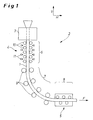
- Fig. 1 schematically a continuous casting 2 is shown.
- Liquid metallic material emerges vertically downwards as a strand 1 from a mold 3 in the conveying direction F and is gradually redirected from the vertical V to the horizontal H along a casting arc section.
- a vertical strand guide 4 having a number of rollers 10 which guide the metal strip 1.
- a number of rollers 9 act as a means for bending the metal strip 1 from the vertical V to the horizontal H.
- this is a straightening driver which subjects the metal strip 1 to mechanical straightening by means of mechanical deformation and can also be provided with a rolling process, which is usually followed.
- the area of the metal strip from the exit from the mold 3 to the mechanical deformation is subdivided into three sections: in a first section 6
- a second section 7 virtually no more cooling is made, and located in the metal strip 1 heat warms the cooled surface of the metal strip 1 again.
- the mechanical deformation takes place.
- the exemplary embodiment shows that the first section 6 is again subdivided into subsections. This allows in a simple manner an intermittent cooling in the first section 6, namely an intensive cooling in a first section and a weaker or reduced or even no cooling in the at least one further follower section, which in turn can then be followed by an intensive cooling section and so on.
- the cooling of the metal strip 1 is carried out with first coolants 11 and second coolants 12, as is best in Fig. 2 can be seen.
- the first cooling means 11 work so intensively that a large cooling capacity is present.
- the second coolant 12 is conventional and per se known coolant, which are used in previously known continuous casting.
- the design of the coolant 11 is carried out so that the cooling of the metal strip 1 in the first section 6, in particular in the immediately following part of the mold 3, its in the extension direction F uppermost or frontmost coolant for descaling and thus cleaning the surfaces of the metal strip 1
- High pressure switchable with a heat transfer coefficient between 3,000 and 10,000 W / (m 2 K) takes place. In this case, the majority of the cooling goes back to the first coolant 11.
- the heat transfer coefficient (symbol ⁇ ), also called heat transfer coefficient or heat transfer coefficient, is a proportionality factor which determines the intensity of the heat transfer at a surface.
- the heat transfer coefficient here describes the ability of a gas or a liquid to dissipate energy from the surface of a substance or to deliver it to the surface. It depends, among other things, on the specific heat, the density and the thermal conductivity coefficient of the heat-dissipating and the heat-delivering medium. The calculation of the coefficient for heat conduction usually takes place via the temperature difference of the media involved.
- the factors mentioned immediately show that the design of the intensity of the cooling has direct effects on the heat transfer coefficient.
- the cooling capacity can be influenced for example by changing the horizontal distance between the cooling means 11 and 12 and the metal strip 1; it becomes lower, the greater the distance.
- the mentioned coolant 11 are not needed for every application. Therefore, they are - how it looks Fig. 2 emerges - arranged displaceably in the vertical direction, with corresponding means of movement are not shown. Shown are the coolant 11 in solid lines in its active position, wherein the ejected jet cooling water takes the outlined course.
- the coolant 11 can be moved vertically in the position shown in dashed lines, so that a classic, lower, d. H. less intensive cooling by the coolant 12 is accomplished.
- the cooling means 11 have a housing 13, on whose side facing the metal strip 1, two nozzles 14 and 15 or rows of nozzles extending perpendicularly to the plane of the drawing over the metal strip 1 are arranged.
- the housing 13 has in its interior according to two chambers 16, 17 which are each fluidly connected to a water supply line.
- the nozzles 14 and 15 are designed differently, so that different amounts of water currents can be directed to the metal strip 1 - depending on the technological need to achieve a scale-free as possible and thus cleaned surface of Metallbandes1.
- the nozzles may also be designed as nozzle bars, d. H. as a beam which extends across the width of the metal strip 1 and passes cooling water from a number of nozzle openings on the strip surface.
- the proposed device for intensive cooling thus has a housing which can be pushed with a small distance between the continuous casting guide rollers 10 and thus forms a cooling channel.
- the housing 13 can be protected from destruction by a fender (not shown) in the event of a breakthrough, so that it can be reused in this case.
- a fender not shown
- the cooling effect can be influenced. Further influence on the cooling effect can be achieved by the construction of the housing and the nozzles 14, 15.
- a subcooling of the edge region of the metal strip can also be avoided by switching on and off of nozzle groups.
- spray nozzles can also be used. These should be distributed close to each other across the width of the metal strip to achieve the necessary cooling and cooling and grain refining and descaling effect associated therewith. By switching these groups on and off, subcooling of the edges can also be avoided.
- the nozzles can be deactivated, swung away, moved away or the flow of cooling medium (water) can be lowered to ensure standard cooling.
- additional cooling consisting of several provided with spray nozzles spray bar are used with a separate water supply.
- the additional spray bars are only switched on when needed.
- subcooling of the edges can also be avoided here by switching on and off of nozzle groups.
- Such nozzles are not used for the present invention because of their excessive cooling effect and the associated low surface temperature of the surface of the metal strip or they are not useful here.
- the core idea according to the invention can therefore be seen in the fact that intensive cooling takes place in the area of secondary cooling, in particular in thin slab plants, in order to achieve a cleaning of the surface of the slab in which the intensive cooling begins shortly after the mold, viewed in the conveying direction.
- the cooling ends so early that reheating can take place above the temperature Ac3 or Ar3 before mechanical stresses occur, as is the case, for example, with the bending driver.
- the aim is to have no or only a small excretion on the grain boundaries.
- the proposed device for intensive cooling has a significantly higher cooling effect than is otherwise the case with the secondary cooling of a continuous casting plant.
- the usual heat transfer coefficients are between 500 W / (m 2 K) and 2,500 W / (m 2 K).
- descaling plants are known in which a cooling device is used which realizes heat transfer numbers of more than 20,000 W / (m 2 K).
- the heat transfer rates required here are - as already indicated above - material-dependent and also dependent on the casting speed. They result from the maximum cooling rate at which no martensite or interstitial structure is yet produced.
- the cooling rate is about 2,500 ° C / min, which corresponds to a heat transfer coefficient of about 5,500 W / (m 2 K) at a casting speed of 5.0 m / min.
- the intensity of the cooling can be varied by the number of nozzles arranged side by side. Furthermore, it is also possible to use additional nozzle bars to conventional spray cooling devices.
- the length of the intensive cooling - viewed in the conveying direction F - is determined by the solidification structure to 2 mm below the surface of the metal strip. In the case of dendritic solidification, the intensive cooling length is lengthened by about a factor of 2 to 3 compared with the length in the case of globulitic solidification.
- the heat transfer coefficient also results from the design of the coolant, in this case in particular the first coolant 11.
- the number is selected specifically in the claimed range, since the conditions for intensive cooling of the finished metal strip 1 are optimal and at the same time a largely scaling belt surface can be achieved.
Landscapes
- Engineering & Computer Science (AREA)
- Mechanical Engineering (AREA)
- Continuous Casting (AREA)
- Heat Treatments In General, Especially Conveying And Cooling (AREA)
- Metal Rolling (AREA)
- Casting Devices For Molds (AREA)
Priority Applications (1)
| Application Number | Priority Date | Filing Date | Title |
|---|---|---|---|
| PL06841185T PL1937429T3 (pl) | 2006-01-11 | 2006-12-28 | Sposób i urządzenie do odlewania ciągłego |
Applications Claiming Priority (3)
| Application Number | Priority Date | Filing Date | Title |
|---|---|---|---|
| DE102006001464 | 2006-01-11 | ||
| DE102006056683A DE102006056683A1 (de) | 2006-01-11 | 2006-11-30 | Verfahren und Vorrichtung zum Stranggießen |
| PCT/EP2006/012560 WO2007087893A1 (de) | 2006-01-11 | 2006-12-28 | Verfahren und vorrichtung zum stranggiessen |
Publications (2)
| Publication Number | Publication Date |
|---|---|
| EP1937429A1 EP1937429A1 (de) | 2008-07-02 |
| EP1937429B1 true EP1937429B1 (de) | 2009-03-18 |
Family
ID=37909512
Family Applications (1)
| Application Number | Title | Priority Date | Filing Date |
|---|---|---|---|
| EP06841185A Active EP1937429B1 (de) | 2006-01-11 | 2006-12-28 | Verfahren und vorrichtung zum stranggiessen |
Country Status (16)
| Country | Link |
|---|---|
| US (2) | US8596335B2 (enExample) |
| EP (1) | EP1937429B1 (enExample) |
| JP (1) | JP5039712B2 (enExample) |
| KR (1) | KR101037078B1 (enExample) |
| AT (1) | ATE425827T1 (enExample) |
| AU (1) | AU2006337470B2 (enExample) |
| BR (1) | BRPI0620971B1 (enExample) |
| CA (1) | CA2635128C (enExample) |
| DE (2) | DE102006056683A1 (enExample) |
| EG (1) | EG24892A (enExample) |
| ES (1) | ES2321234T3 (enExample) |
| MY (1) | MY143585A (enExample) |
| PL (1) | PL1937429T3 (enExample) |
| RU (1) | RU2377096C1 (enExample) |
| TW (1) | TWI382888B (enExample) |
| WO (1) | WO2007087893A1 (enExample) |
Cited By (3)
| Publication number | Priority date | Publication date | Assignee | Title |
|---|---|---|---|---|
| DE102014214374A1 (de) | 2014-07-23 | 2016-01-28 | Sms Group Gmbh | Verfahren zur Herstellung eines metallischen Produkts |
| DE102017213842A1 (de) | 2017-08-08 | 2019-02-14 | Sms Group Gmbh | Verfahren und Anlage zum Stranggießen eines metallischen Produkts |
| DE102023211833A1 (de) * | 2023-11-28 | 2025-05-28 | Sms Group Gmbh | Vorrichtung und Verfahren zum Kühlen eines Gießstrangs in einer Stranggießanlage |
Families Citing this family (22)
| Publication number | Priority date | Publication date | Assignee | Title |
|---|---|---|---|---|
| DE102008032970A1 (de) * | 2008-07-10 | 2010-01-14 | Sms Siemag Aktiengesellschaft | Verfahren zum Abkühlen eines aus einer Stranggießkokille austretenden Stranges |
| US8365808B1 (en) | 2012-05-17 | 2013-02-05 | Almex USA, Inc. | Process and apparatus for minimizing the potential for explosions in the direct chill casting of aluminum lithium alloys |
| US8479802B1 (en) * | 2012-05-17 | 2013-07-09 | Almex USA, Inc. | Apparatus for casting aluminum lithium alloys |
| KR101406652B1 (ko) | 2012-09-05 | 2014-06-11 | 주식회사 포스코 | 냉각노즐 커버장치 |
| US9764380B2 (en) | 2013-02-04 | 2017-09-19 | Almex USA, Inc. | Process and apparatus for direct chill casting |
| JP5854071B2 (ja) * | 2013-03-29 | 2016-02-09 | Jfeスチール株式会社 | 鋼の連続鋳造方法 |
| DE102013212952A1 (de) | 2013-07-03 | 2015-01-22 | Sms Siemag Ag | Vorrichtung und Verfahren zum Stützen eines Stranges beim Stranggießen |
| US9936541B2 (en) | 2013-11-23 | 2018-04-03 | Almex USA, Inc. | Alloy melting and holding furnace |
| WO2016114208A1 (ja) * | 2015-01-15 | 2016-07-21 | 新日鐵住金株式会社 | 鋳片の連続鋳造方法 |
| KR101736574B1 (ko) * | 2015-06-04 | 2017-05-17 | 주식회사 포스코 | 응고 장치 |
| EP3318342A1 (de) * | 2016-11-07 | 2018-05-09 | Primetals Technologies Austria GmbH | Verfahren zum betreiben einer giesswalzverbundanlage |
| CN109996637A (zh) * | 2016-11-18 | 2019-07-09 | Sms集团有限公司 | 用于制造连续的带状复合材料的方法以及设备 |
| CN108672668A (zh) * | 2018-03-29 | 2018-10-19 | 马鞍山钢铁股份有限公司 | 一种控制连铸过程中铸坯凝固组织结构的方法及其控制装置 |
| CN109158561B (zh) * | 2018-04-25 | 2024-03-22 | 西安麦特沃金液控技术有限公司 | 一种引锭杆处理装置及立式连续铸造系统 |
| CN110369686A (zh) * | 2019-07-03 | 2019-10-25 | 西安理工大学 | 一种铸铁水平连铸三次喷冷装置 |
| KR20210051247A (ko) | 2019-10-30 | 2021-05-10 | 이준수 | 연속 주조용 세그먼트 모니터링 방법 |
| CN111495971A (zh) * | 2020-05-06 | 2020-08-07 | 义乌聚龙自动化科技有限公司 | 一种铝合金板连铸连轧设备和方法 |
| IT202000010909A1 (it) * | 2020-05-13 | 2021-11-13 | Danieli Off Mecc | Apparato di raffreddamento secondario in una macchina per colata continua di prodotti metallici |
| BR112022022196A2 (pt) * | 2020-07-22 | 2023-01-31 | Novelis Inc | Sistema de molde de fundição com resfriamento direto |
| DE102020211720A1 (de) | 2020-09-18 | 2022-03-24 | Sms Group Gmbh | Verfahren und Sprüheinrichtung zur thermischen Oberflächenbehandlung eines metallischen Produkts |
| CN113426970B (zh) * | 2021-06-11 | 2023-02-03 | 一重集团大连工程技术有限公司 | Φ1000mm-Φ2000mm大型圆坯的立式半连续生产装置及其生产工序 |
| CN115958174B (zh) * | 2022-12-30 | 2025-06-20 | 张家港中美超薄带科技有限公司 | 一种马氏体薄钢带的生产及精整方法 |
Family Cites Families (38)
| Publication number | Priority date | Publication date | Assignee | Title |
|---|---|---|---|---|
| US3358358A (en) * | 1964-12-31 | 1967-12-19 | United States Steel Corp | Method of reducing width of metal slabs |
| AT314752B (de) * | 1971-04-30 | 1974-04-25 | Voest Ag | Stranggießanlage für Brammen |
| AT323921B (de) * | 1973-07-27 | 1975-08-11 | Voest Ag | Kuhleinrichtung für kontinuierlich zu giessende stränge |
| CH580454A5 (enExample) * | 1974-04-26 | 1976-10-15 | Concast Ag | |
| BE831560A (fr) * | 1975-07-18 | 1976-01-19 | Perfectionnements aux procedes de coulee continue des metaux | |
| JPS6174763A (ja) | 1984-09-17 | 1986-04-17 | Sumitomo Heavy Ind Ltd | 連続鋳造機における鋳片の表面温度制御方法 |
| JPS63112058A (ja) * | 1986-10-28 | 1988-05-17 | Mitsubishi Heavy Ind Ltd | 連続鋳造方法 |
| SU1458071A1 (ru) * | 1987-03-18 | 1989-02-15 | Ждановский металлургический институт | Способ непрерывной разливки |
| EP0343103B1 (de) | 1988-05-19 | 1992-11-11 | Alusuisse-Lonza Services Ag | Verfahren und Vorrichtung zum Kühlen eines Gegenstandes |
| JPH048645A (ja) | 1990-04-26 | 1992-01-13 | Seiko Epson Corp | 自動車電話装置 |
| JPH0480645A (ja) | 1990-07-23 | 1992-03-13 | Nissan Motor Co Ltd | 欠陥検査装置 |
| AT398396B (de) * | 1993-02-16 | 1994-11-25 | Voest Alpine Ind Anlagen | Verfahren zum herstellen eines bandes, vorstreifens oder einer bramme |
| DE69431178T3 (de) | 1993-10-29 | 2014-03-20 | Danieli & C. Officine Meccaniche S.P.A. | Verfahren zur thermischen Oberflächenbehandlung eines Stranges |
| DE4416752A1 (de) | 1994-05-13 | 1995-11-16 | Schloemann Siemag Ag | Verfahren und Produktionsanlage zur Erzeugung von Warmbreitband |
| JPH08132207A (ja) * | 1994-11-09 | 1996-05-28 | Sumitomo Metal Ind Ltd | 鋼の連続鋳造時における表面割れ抑制方法 |
| JPH08267205A (ja) * | 1995-03-31 | 1996-10-15 | Kawasaki Steel Corp | 連続鋳造機 |
| JP2944476B2 (ja) | 1995-08-29 | 1999-09-06 | 川崎製鉄株式会社 | 鋳片の表面割れを防止した連続鍛圧法 |
| JPH09141408A (ja) * | 1995-11-24 | 1997-06-03 | Kawasaki Steel Corp | 連続鋳造の二次冷却方法 |
| JP3058079B2 (ja) | 1996-02-23 | 2000-07-04 | 住友金属工業株式会社 | 鋼の連続鋳造方法 |
| CA2332933C (en) | 1998-07-10 | 2007-11-06 | Ipsco Inc. | Method and apparatus for producing martensite- or bainite-rich steel using steckel mill and controlled cooling |
| JP2000233266A (ja) * | 1999-02-15 | 2000-08-29 | Nkk Corp | 表面性状の良好な鋼板の製造方法 |
| DE19931331A1 (de) * | 1999-07-07 | 2001-01-18 | Siemens Ag | Verfahren und Einrichtung zum Herstellen eines Stranges aus Metall |
| DE19960593C2 (de) | 1999-12-16 | 2001-11-22 | Sms Demag Ag | Vorrichtung zum Kühlen eines metallischen Gussstrangs |
| JP3555538B2 (ja) * | 2000-02-21 | 2004-08-18 | Jfeスチール株式会社 | 連続鋳造鋳片の直送圧延方法 |
| AT409352B (de) | 2000-06-02 | 2002-07-25 | Voest Alpine Ind Anlagen | Verfahren zum stranggiessen eines metallstranges |
| JP2002079356A (ja) | 2000-09-06 | 2002-03-19 | Daido Steel Co Ltd | 連続鋳造における2次冷却方法 |
| JP3705101B2 (ja) * | 2000-09-12 | 2005-10-12 | 住友金属工業株式会社 | 連続鋳造方法 |
| EP1243343B1 (de) * | 2001-03-22 | 2003-08-13 | Lechler GmbH | Zweistoffsprühdüse |
| JP3702807B2 (ja) * | 2001-04-11 | 2005-10-05 | 住友金属工業株式会社 | 連続鋳造方法 |
| BRPI0111910B1 (pt) * | 2001-04-25 | 2016-07-26 | Jfe Eng Corp | método de produção para um produto de aço lingotado continuamente e equipamento para medir o estado de solidificação de um produto de aço lingotado continuamente |
| DE10138794A1 (de) * | 2001-08-07 | 2003-02-27 | Sms Demag Ag | Verfahren und Anlage zur Produktion von Flach- und Langprodukten |
| DE50211289D1 (de) * | 2002-02-28 | 2008-01-10 | Lechler Gmbh | Kühlanordnung für das Walzgerüst einer Stranggussanlage |
| JP2003275852A (ja) * | 2002-03-18 | 2003-09-30 | Jfe Steel Kk | 鋼の連続鋳造方法および装置 |
| ES2210203T3 (es) | 2002-04-18 | 2004-07-01 | Lechler Gmbh | Boquilla rociadora binaria con una pieza de insercion intercambiable. |
| JP4042541B2 (ja) | 2002-11-19 | 2008-02-06 | Jfeスチール株式会社 | 連続鋳造鋳片の二次冷却装置および二次冷却方法 |
| DE10255550B3 (de) | 2002-11-28 | 2004-01-22 | Sms Demag Ag | Verfahren und Einrichtung zum Stranggießen von Brammen-, Dünnbrammen-, Vorblock-, Vorprofil-, Knüppelsträngen und dgl. aus flüssigem Metall, insbesondere aus Stahlwerkstoff |
| JP4321325B2 (ja) * | 2004-03-29 | 2009-08-26 | Jfeスチール株式会社 | 連続鋳造鋳片の二次冷却方法 |
| AT503526B1 (de) | 2006-04-25 | 2008-07-15 | Voest Alpine Ind Anlagen | Spritzdüsen-verstelleinrichtung |
-
2006
- 2006-11-30 DE DE102006056683A patent/DE102006056683A1/de not_active Withdrawn
- 2006-12-28 AT AT06841185T patent/ATE425827T1/de active
- 2006-12-28 BR BRPI0620971-8A patent/BRPI0620971B1/pt not_active IP Right Cessation
- 2006-12-28 CA CA2635128A patent/CA2635128C/en not_active Expired - Fee Related
- 2006-12-28 PL PL06841185T patent/PL1937429T3/pl unknown
- 2006-12-28 ES ES06841185T patent/ES2321234T3/es active Active
- 2006-12-28 WO PCT/EP2006/012560 patent/WO2007087893A1/de not_active Ceased
- 2006-12-28 US US12/087,305 patent/US8596335B2/en not_active Expired - Fee Related
- 2006-12-28 MY MYPI20082460A patent/MY143585A/en unknown
- 2006-12-28 JP JP2008548950A patent/JP5039712B2/ja not_active Expired - Fee Related
- 2006-12-28 KR KR1020087017402A patent/KR101037078B1/ko not_active Expired - Fee Related
- 2006-12-28 DE DE502006003212T patent/DE502006003212D1/de active Active
- 2006-12-28 RU RU2008132828/02A patent/RU2377096C1/ru not_active IP Right Cessation
- 2006-12-28 EP EP06841185A patent/EP1937429B1/de active Active
- 2006-12-28 AU AU2006337470A patent/AU2006337470B2/en not_active Ceased
- 2006-12-29 TW TW095149753A patent/TWI382888B/zh not_active IP Right Cessation
-
2008
- 2008-07-07 EG EG2008071146A patent/EG24892A/xx active
-
2012
- 2012-01-19 US US13/353,511 patent/US8522858B2/en not_active Expired - Fee Related
Cited By (5)
| Publication number | Priority date | Publication date | Assignee | Title |
|---|---|---|---|---|
| DE102014214374A1 (de) | 2014-07-23 | 2016-01-28 | Sms Group Gmbh | Verfahren zur Herstellung eines metallischen Produkts |
| US10894994B2 (en) | 2014-07-23 | 2021-01-19 | Sms Group Gmbh | Method for producing a metal product |
| DE102017213842A1 (de) | 2017-08-08 | 2019-02-14 | Sms Group Gmbh | Verfahren und Anlage zum Stranggießen eines metallischen Produkts |
| DE102023211833A1 (de) * | 2023-11-28 | 2025-05-28 | Sms Group Gmbh | Vorrichtung und Verfahren zum Kühlen eines Gießstrangs in einer Stranggießanlage |
| EP4563263A1 (de) | 2023-11-28 | 2025-06-04 | SMS Group GmbH | Vorrichtung und verfahren zum kühlen eines giessstrangs in einer stranggiessanlage |
Also Published As
| Publication number | Publication date |
|---|---|
| JP5039712B2 (ja) | 2012-10-03 |
| WO2007087893A1 (de) | 2007-08-09 |
| EP1937429A1 (de) | 2008-07-02 |
| TWI382888B (zh) | 2013-01-21 |
| US8522858B2 (en) | 2013-09-03 |
| US20120111527A1 (en) | 2012-05-10 |
| US20090095438A1 (en) | 2009-04-16 |
| AU2006337470B2 (en) | 2010-02-04 |
| KR101037078B1 (ko) | 2011-05-26 |
| ATE425827T1 (de) | 2009-04-15 |
| DE502006003212D1 (de) | 2009-04-30 |
| PL1937429T3 (pl) | 2009-08-31 |
| TW200732062A (en) | 2007-09-01 |
| BRPI0620971B1 (pt) | 2015-07-21 |
| MY143585A (en) | 2011-05-31 |
| US8596335B2 (en) | 2013-12-03 |
| JP2009522110A (ja) | 2009-06-11 |
| ES2321234T3 (es) | 2009-06-03 |
| CA2635128C (en) | 2012-07-17 |
| BRPI0620971A2 (pt) | 2011-11-29 |
| DE102006056683A1 (de) | 2007-07-12 |
| EG24892A (en) | 2010-12-13 |
| KR20080081173A (ko) | 2008-09-08 |
| AU2006337470A1 (en) | 2007-08-09 |
| CA2635128A1 (en) | 2007-08-09 |
| RU2377096C1 (ru) | 2009-12-27 |
Similar Documents
| Publication | Publication Date | Title |
|---|---|---|
| EP1937429B1 (de) | Verfahren und vorrichtung zum stranggiessen | |
| EP2349612B2 (de) | Verfahren und stranggiessanlage zum herstellen von dicken brammen | |
| DE3127348C2 (de) | Verfahren zum Kühlen eines Gußstrangs in einer Bogenstranggießanlage | |
| EP2516079B1 (de) | Verfahren zum warmwalzen einer bramme und warmwalzwerk | |
| EP3558563B1 (de) | Verfahren zur endlosen herstellung eines aufgewickelten warmbands in einer giess-walz-verbundanlage und giess-walz-verbundanlage | |
| DE212009000056U1 (de) | Stranggießanlage zum Herstellen von dicken Brammen | |
| DE102009036378A1 (de) | Verfahren und Vorrichtung zum Herstellen eines mikrolegierten Stahls, insbesondere eines Röhrenstahls | |
| EP3016762B1 (de) | Giesswalzanlage und verfahren zum herstellen von metallischem walzgut | |
| WO2016165933A1 (de) | GIEß-WALZ-ANLAGE UND VERFAHREN ZU DEREN BETRIEB | |
| WO2015014865A1 (de) | GIEßWALZANLAGE ZUM HERSTELLEN VON METALLBÄNDERN | |
| DE102009030793A1 (de) | Vorrichtung und Verfahren zum horizontalen Gießen eines Metallbandes | |
| EP0998993B1 (de) | Verfahren und Vorrichtung zum Kühlen von walzwarmem Walzgut, insbesondere Warmbreitband | |
| DE10302265A1 (de) | Verfahren und Vorrichtung zur Erzeugung von stranggegossenen Stahlbrammen | |
| DD284175A5 (de) | Verfahren zum kuehlen eines metallischen gegenstandes waehrend des stranggiessens | |
| DE60316568T2 (de) | Bandtemperaturregelvorrichtung in einer kontinuierlichen bandgiessanlage | |
| AT525563B1 (de) | Trockengiessen in einer giess-walz-verbundanlage | |
| DE102015210865A1 (de) | Gieß-Walz-Anlage und Verfahren zu deren Betrieb | |
| WO2011038925A1 (de) | Verfahren zum bandgiessen von stahl und anlage zum bandgiessen | |
| DE19718530B4 (de) | Verfahren zum Kühlen von walzwarmem Walzgut und Vorrichtung zur Durchführung des Verfahrens und Verwendung der Vorrichtung | |
| DE19831998A1 (de) | Stranggießkokille | |
| EP3097995B1 (de) | Segment einer strangführung einer stranggiessanlage und stranggiessanlage | |
| EP1414603A1 (de) | Verfahren und anlage zur produktion von flach- und langprodukten | |
| EP1356879B1 (de) | Stranggiesskokille | |
| DE3141269A1 (de) | "kuehlverfahren und kuehlvorrichtung fuer langgestrecktes, heisses metallgut, insbesondere fuer stranggegossene knueppel- bzw. bloomstraenge" | |
| DE1458123C (de) | Verfahren zum kontinuierlichen Her stellen von mehreren profilierten Stran gen und Anlage zur Durchfuhrung dieses Verfahrens |
Legal Events
| Date | Code | Title | Description |
|---|---|---|---|
| PUAI | Public reference made under article 153(3) epc to a published international application that has entered the european phase |
Free format text: ORIGINAL CODE: 0009012 |
|
| 17P | Request for examination filed |
Effective date: 20080517 |
|
| AK | Designated contracting states |
Kind code of ref document: A1 Designated state(s): AT BE BG CH CY CZ DE DK EE ES FI FR GB GR HU IE IS IT LI LT LU LV MC NL PL PT RO SE SI SK TR |
|
| GRAP | Despatch of communication of intention to grant a patent |
Free format text: ORIGINAL CODE: EPIDOSNIGR1 |
|
| GRAS | Grant fee paid |
Free format text: ORIGINAL CODE: EPIDOSNIGR3 |
|
| GRAA | (expected) grant |
Free format text: ORIGINAL CODE: 0009210 |
|
| DAX | Request for extension of the european patent (deleted) | ||
| AK | Designated contracting states |
Kind code of ref document: B1 Designated state(s): AT BE BG CH CY CZ DE DK EE ES FI FR GB GR HU IE IS IT LI LT LU LV MC NL PL PT RO SE SI SK TR |
|
| REG | Reference to a national code |
Ref country code: GB Ref legal event code: FG4D Free format text: NOT ENGLISH |
|
| REG | Reference to a national code |
Ref country code: CH Ref legal event code: EP |
|
| REG | Reference to a national code |
Ref country code: IE Ref legal event code: FG4D Free format text: LANGUAGE OF EP DOCUMENT: GERMAN |
|
| REF | Corresponds to: |
Ref document number: 502006003212 Country of ref document: DE Date of ref document: 20090430 Kind code of ref document: P |
|
| REG | Reference to a national code |
Ref country code: ES Ref legal event code: FG2A Ref document number: 2321234 Country of ref document: ES Kind code of ref document: T3 |
|
| RAP2 | Party data changed (patent owner data changed or rights of a patent transferred) |
Owner name: SMS SIEMAG AG |
|
| PG25 | Lapsed in a contracting state [announced via postgrant information from national office to epo] |
Ref country code: FI Free format text: LAPSE BECAUSE OF FAILURE TO SUBMIT A TRANSLATION OF THE DESCRIPTION OR TO PAY THE FEE WITHIN THE PRESCRIBED TIME-LIMIT Effective date: 20090318 Ref country code: SI Free format text: LAPSE BECAUSE OF FAILURE TO SUBMIT A TRANSLATION OF THE DESCRIPTION OR TO PAY THE FEE WITHIN THE PRESCRIBED TIME-LIMIT Effective date: 20090318 Ref country code: LT Free format text: LAPSE BECAUSE OF FAILURE TO SUBMIT A TRANSLATION OF THE DESCRIPTION OR TO PAY THE FEE WITHIN THE PRESCRIBED TIME-LIMIT Effective date: 20090318 Ref country code: NL Free format text: LAPSE BECAUSE OF FAILURE TO SUBMIT A TRANSLATION OF THE DESCRIPTION OR TO PAY THE FEE WITHIN THE PRESCRIBED TIME-LIMIT Effective date: 20090318 |
|
| NLT2 | Nl: modifications (of names), taken from the european patent patent bulletin |
Owner name: SMS SIEMAG AG Effective date: 20090617 |
|
| PG25 | Lapsed in a contracting state [announced via postgrant information from national office to epo] |
Ref country code: SE Free format text: LAPSE BECAUSE OF FAILURE TO SUBMIT A TRANSLATION OF THE DESCRIPTION OR TO PAY THE FEE WITHIN THE PRESCRIBED TIME-LIMIT Effective date: 20090618 Ref country code: LV Free format text: LAPSE BECAUSE OF FAILURE TO SUBMIT A TRANSLATION OF THE DESCRIPTION OR TO PAY THE FEE WITHIN THE PRESCRIBED TIME-LIMIT Effective date: 20090318 |
|
| REG | Reference to a national code |
Ref country code: PL Ref legal event code: T3 |
|
| NLV1 | Nl: lapsed or annulled due to failure to fulfill the requirements of art. 29p and 29m of the patents act | ||
| REG | Reference to a national code |
Ref country code: HU Ref legal event code: AG4A Ref document number: E005544 Country of ref document: HU |
|
| REG | Reference to a national code |
Ref country code: IE Ref legal event code: FD4D |
|
| PG25 | Lapsed in a contracting state [announced via postgrant information from national office to epo] |
Ref country code: PT Free format text: LAPSE BECAUSE OF FAILURE TO SUBMIT A TRANSLATION OF THE DESCRIPTION OR TO PAY THE FEE WITHIN THE PRESCRIBED TIME-LIMIT Effective date: 20090827 Ref country code: EE Free format text: LAPSE BECAUSE OF FAILURE TO SUBMIT A TRANSLATION OF THE DESCRIPTION OR TO PAY THE FEE WITHIN THE PRESCRIBED TIME-LIMIT Effective date: 20090318 Ref country code: IE Free format text: LAPSE BECAUSE OF FAILURE TO SUBMIT A TRANSLATION OF THE DESCRIPTION OR TO PAY THE FEE WITHIN THE PRESCRIBED TIME-LIMIT Effective date: 20090318 |
|
| PG25 | Lapsed in a contracting state [announced via postgrant information from national office to epo] |
Ref country code: RO Free format text: LAPSE BECAUSE OF FAILURE TO SUBMIT A TRANSLATION OF THE DESCRIPTION OR TO PAY THE FEE WITHIN THE PRESCRIBED TIME-LIMIT Effective date: 20090318 Ref country code: SK Free format text: LAPSE BECAUSE OF FAILURE TO SUBMIT A TRANSLATION OF THE DESCRIPTION OR TO PAY THE FEE WITHIN THE PRESCRIBED TIME-LIMIT Effective date: 20090318 Ref country code: IS Free format text: LAPSE BECAUSE OF FAILURE TO SUBMIT A TRANSLATION OF THE DESCRIPTION OR TO PAY THE FEE WITHIN THE PRESCRIBED TIME-LIMIT Effective date: 20090718 |
|
| PLBI | Opposition filed |
Free format text: ORIGINAL CODE: 0009260 |
|
| PG25 | Lapsed in a contracting state [announced via postgrant information from national office to epo] |
Ref country code: BG Free format text: LAPSE BECAUSE OF FAILURE TO SUBMIT A TRANSLATION OF THE DESCRIPTION OR TO PAY THE FEE WITHIN THE PRESCRIBED TIME-LIMIT Effective date: 20090618 Ref country code: DK Free format text: LAPSE BECAUSE OF FAILURE TO SUBMIT A TRANSLATION OF THE DESCRIPTION OR TO PAY THE FEE WITHIN THE PRESCRIBED TIME-LIMIT Effective date: 20090318 |
|
| 26 | Opposition filed |
Opponent name: SIEMENS VAI METALS TECHNOLOGIES GMBH & CO Effective date: 20091218 |
|
| PLAX | Notice of opposition and request to file observation + time limit sent |
Free format text: ORIGINAL CODE: EPIDOSNOBS2 |
|
| PLAF | Information modified related to communication of a notice of opposition and request to file observations + time limit |
Free format text: ORIGINAL CODE: EPIDOSCOBS2 |
|
| BERE | Be: lapsed |
Owner name: SMS DEMAG A.G. Effective date: 20091231 |
|
| PG25 | Lapsed in a contracting state [announced via postgrant information from national office to epo] |
Ref country code: MC Free format text: LAPSE BECAUSE OF NON-PAYMENT OF DUE FEES Effective date: 20100701 |
|
| PLBB | Reply of patent proprietor to notice(s) of opposition received |
Free format text: ORIGINAL CODE: EPIDOSNOBS3 |
|
| REG | Reference to a national code |
Ref country code: FR Ref legal event code: ST Effective date: 20100831 |
|
| PG25 | Lapsed in a contracting state [announced via postgrant information from national office to epo] |
Ref country code: BE Free format text: LAPSE BECAUSE OF NON-PAYMENT OF DUE FEES Effective date: 20091231 Ref country code: GR Free format text: LAPSE BECAUSE OF FAILURE TO SUBMIT A TRANSLATION OF THE DESCRIPTION OR TO PAY THE FEE WITHIN THE PRESCRIBED TIME-LIMIT Effective date: 20090619 Ref country code: FR Free format text: LAPSE BECAUSE OF NON-PAYMENT OF DUE FEES Effective date: 20091231 |
|
| PLAY | Examination report in opposition despatched + time limit |
Free format text: ORIGINAL CODE: EPIDOSNORE2 |
|
| PLAH | Information related to despatch of examination report in opposition + time limit modified |
Free format text: ORIGINAL CODE: EPIDOSCORE2 |
|
| PGFP | Annual fee paid to national office [announced via postgrant information from national office to epo] |
Ref country code: CZ Payment date: 20101227 Year of fee payment: 5 Ref country code: PL Payment date: 20101129 Year of fee payment: 5 |
|
| PLAH | Information related to despatch of examination report in opposition + time limit modified |
Free format text: ORIGINAL CODE: EPIDOSCORE2 |
|
| PG25 | Lapsed in a contracting state [announced via postgrant information from national office to epo] |
Ref country code: LU Free format text: LAPSE BECAUSE OF NON-PAYMENT OF DUE FEES Effective date: 20091228 |
|
| PGFP | Annual fee paid to national office [announced via postgrant information from national office to epo] |
Ref country code: HU Payment date: 20110107 Year of fee payment: 5 |
|
| PLAB | Opposition data, opponent's data or that of the opponent's representative modified |
Free format text: ORIGINAL CODE: 0009299OPPO |
|
| R26 | Opposition filed (corrected) |
Opponent name: SIEMENS VAI METALS TECHNOLOGIES GMBH Effective date: 20091218 |
|
| PLBC | Reply to examination report in opposition received |
Free format text: ORIGINAL CODE: EPIDOSNORE3 |
|
| REG | Reference to a national code |
Ref country code: CH Ref legal event code: PL |
|
| PG25 | Lapsed in a contracting state [announced via postgrant information from national office to epo] |
Ref country code: CY Free format text: LAPSE BECAUSE OF FAILURE TO SUBMIT A TRANSLATION OF THE DESCRIPTION OR TO PAY THE FEE WITHIN THE PRESCRIBED TIME-LIMIT Effective date: 20090318 |
|
| PG25 | Lapsed in a contracting state [announced via postgrant information from national office to epo] |
Ref country code: CH Free format text: LAPSE BECAUSE OF NON-PAYMENT OF DUE FEES Effective date: 20101231 Ref country code: LI Free format text: LAPSE BECAUSE OF NON-PAYMENT OF DUE FEES Effective date: 20101231 |
|
| APAH | Appeal reference modified |
Free format text: ORIGINAL CODE: EPIDOSCREFNO |
|
| APBM | Appeal reference recorded |
Free format text: ORIGINAL CODE: EPIDOSNREFNO |
|
| APBP | Date of receipt of notice of appeal recorded |
Free format text: ORIGINAL CODE: EPIDOSNNOA2O |
|
| PLCK | Communication despatched that opposition was rejected |
Free format text: ORIGINAL CODE: EPIDOSNREJ1 |
|
| APBQ | Date of receipt of statement of grounds of appeal recorded |
Free format text: ORIGINAL CODE: EPIDOSNNOA3O |
|
| PG25 | Lapsed in a contracting state [announced via postgrant information from national office to epo] |
Ref country code: CZ Free format text: LAPSE BECAUSE OF NON-PAYMENT OF DUE FEES Effective date: 20111228 |
|
| PG25 | Lapsed in a contracting state [announced via postgrant information from national office to epo] |
Ref country code: HU Free format text: LAPSE BECAUSE OF NON-PAYMENT OF DUE FEES Effective date: 20111229 |
|
| REG | Reference to a national code |
Ref country code: PL Ref legal event code: LAPE |
|
| PG25 | Lapsed in a contracting state [announced via postgrant information from national office to epo] |
Ref country code: PL Free format text: LAPSE BECAUSE OF NON-PAYMENT OF DUE FEES Effective date: 20111228 |
|
| PGFP | Annual fee paid to national office [announced via postgrant information from national office to epo] |
Ref country code: TR Payment date: 20131126 Year of fee payment: 8 |
|
| PGFP | Annual fee paid to national office [announced via postgrant information from national office to epo] |
Ref country code: ES Payment date: 20141218 Year of fee payment: 9 |
|
| RAP2 | Party data changed (patent owner data changed or rights of a patent transferred) |
Owner name: SMS GROUP GMBH |
|
| PLAB | Opposition data, opponent's data or that of the opponent's representative modified |
Free format text: ORIGINAL CODE: 0009299OPPO |
|
| REG | Reference to a national code |
Ref country code: DE Ref legal event code: R082 Ref document number: 502006003212 Country of ref document: DE Representative=s name: HEMMERICH & KOLLEGEN, DE Ref country code: DE Ref legal event code: R081 Ref document number: 502006003212 Country of ref document: DE Owner name: SMS GROUP GMBH, DE Free format text: FORMER OWNER: SMS SIEMAG AKTIENGESELLSCHAFT, 40237 DUESSELDORF, DE |
|
| PLAB | Opposition data, opponent's data or that of the opponent's representative modified |
Free format text: ORIGINAL CODE: 0009299OPPO |
|
| R26 | Opposition filed (corrected) |
Opponent name: SIEMENS VAI METALS TECHNOLOGIES GMBH Effective date: 20091218 |
|
| REG | Reference to a national code |
Ref country code: DE Ref legal event code: R100 Ref document number: 502006003212 Country of ref document: DE |
|
| APBU | Appeal procedure closed |
Free format text: ORIGINAL CODE: EPIDOSNNOA9O |
|
| R26 | Opposition filed (corrected) |
Opponent name: PRIMETALS TECHNOLOGIES AUSTRIA GMBH Effective date: 20091218 |
|
| PLBN | Opposition rejected |
Free format text: ORIGINAL CODE: 0009273 |
|
| STAA | Information on the status of an ep patent application or granted ep patent |
Free format text: STATUS: OPPOSITION REJECTED |
|
| 27O | Opposition rejected |
Effective date: 20150916 |
|
| PG25 | Lapsed in a contracting state [announced via postgrant information from national office to epo] |
Ref country code: ES Free format text: LAPSE BECAUSE OF NON-PAYMENT OF DUE FEES Effective date: 20151229 |
|
| PG25 | Lapsed in a contracting state [announced via postgrant information from national office to epo] |
Ref country code: TR Free format text: LAPSE BECAUSE OF NON-PAYMENT OF DUE FEES Effective date: 20151228 |
|
| REG | Reference to a national code |
Ref country code: ES Ref legal event code: FD2A Effective date: 20180628 |
|
| PGFP | Annual fee paid to national office [announced via postgrant information from national office to epo] |
Ref country code: GB Payment date: 20201223 Year of fee payment: 15 |
|
| GBPC | Gb: european patent ceased through non-payment of renewal fee |
Effective date: 20211228 |
|
| PG25 | Lapsed in a contracting state [announced via postgrant information from national office to epo] |
Ref country code: GB Free format text: LAPSE BECAUSE OF NON-PAYMENT OF DUE FEES Effective date: 20211228 |
|
| P01 | Opt-out of the competence of the unified patent court (upc) registered |
Effective date: 20230707 |
|
| PGFP | Annual fee paid to national office [announced via postgrant information from national office to epo] |
Ref country code: DE Payment date: 20241210 Year of fee payment: 19 |
|
| PGFP | Annual fee paid to national office [announced via postgrant information from national office to epo] |
Ref country code: AT Payment date: 20241220 Year of fee payment: 19 |
|
| PGFP | Annual fee paid to national office [announced via postgrant information from national office to epo] |
Ref country code: IT Payment date: 20241227 Year of fee payment: 19 |