EP1937429B1 - Verfahren und vorrichtung zum stranggiessen - Google Patents
Verfahren und vorrichtung zum stranggiessen Download PDFInfo
- Publication number
- EP1937429B1 EP1937429B1 EP06841185A EP06841185A EP1937429B1 EP 1937429 B1 EP1937429 B1 EP 1937429B1 EP 06841185 A EP06841185 A EP 06841185A EP 06841185 A EP06841185 A EP 06841185A EP 1937429 B1 EP1937429 B1 EP 1937429B1
- Authority
- EP
- European Patent Office
- Prior art keywords
- cooling
- metal strip
- section
- continuous casting
- strip
- Prior art date
- Legal status (The legal status is an assumption and is not a legal conclusion. Google has not performed a legal analysis and makes no representation as to the accuracy of the status listed.)
- Active
Links
- 238000000034 method Methods 0.000 title claims abstract description 26
- 238000009749 continuous casting Methods 0.000 title claims abstract description 24
- 238000001816 cooling Methods 0.000 claims abstract description 100
- 229910052751 metal Inorganic materials 0.000 claims abstract description 92
- 239000002184 metal Substances 0.000 claims abstract description 92
- 238000010438 heat treatment Methods 0.000 claims abstract description 4
- 238000005096 rolling process Methods 0.000 claims abstract description 4
- 238000005452 bending Methods 0.000 claims description 11
- 239000012809 cooling fluid Substances 0.000 claims description 6
- 229910001338 liquidmetal Inorganic materials 0.000 claims description 5
- 239000002826 coolant Substances 0.000 abstract description 31
- 239000007788 liquid Substances 0.000 abstract description 3
- 230000009466 transformation Effects 0.000 abstract description 3
- 238000000844 transformation Methods 0.000 abstract 1
- 230000000694 effects Effects 0.000 description 11
- 239000007921 spray Substances 0.000 description 8
- XLYOFNOQVPJJNP-UHFFFAOYSA-N water Substances O XLYOFNOQVPJJNP-UHFFFAOYSA-N 0.000 description 8
- 229910001566 austenite Inorganic materials 0.000 description 4
- 238000005266 casting Methods 0.000 description 4
- 238000005336 cracking Methods 0.000 description 4
- 238000006243 chemical reaction Methods 0.000 description 3
- 238000004140 cleaning Methods 0.000 description 3
- 239000000498 cooling water Substances 0.000 description 3
- 238000009826 distribution Methods 0.000 description 3
- 239000000463 material Substances 0.000 description 3
- 238000003303 reheating Methods 0.000 description 3
- 230000035939 shock Effects 0.000 description 3
- 238000007711 solidification Methods 0.000 description 3
- 230000008023 solidification Effects 0.000 description 3
- 229910000859 α-Fe Inorganic materials 0.000 description 3
- RYGMFSIKBFXOCR-UHFFFAOYSA-N Copper Chemical compound [Cu] RYGMFSIKBFXOCR-UHFFFAOYSA-N 0.000 description 2
- 229910000831 Steel Inorganic materials 0.000 description 2
- 229910052782 aluminium Inorganic materials 0.000 description 2
- -1 aluminum nitrides Chemical class 0.000 description 2
- 229910052802 copper Inorganic materials 0.000 description 2
- 239000010949 copper Substances 0.000 description 2
- 230000001419 dependent effect Effects 0.000 description 2
- 230000029142 excretion Effects 0.000 description 2
- 229910000734 martensite Inorganic materials 0.000 description 2
- 238000007670 refining Methods 0.000 description 2
- 239000010959 steel Substances 0.000 description 2
- 229910000975 Carbon steel Inorganic materials 0.000 description 1
- 238000009825 accumulation Methods 0.000 description 1
- 230000002411 adverse Effects 0.000 description 1
- 230000015572 biosynthetic process Effects 0.000 description 1
- 238000010276 construction Methods 0.000 description 1
- 230000006378 damage Effects 0.000 description 1
- 238000006073 displacement reaction Methods 0.000 description 1
- 238000005516 engineering process Methods 0.000 description 1
- 230000003628 erosive effect Effects 0.000 description 1
- 238000000605 extraction Methods 0.000 description 1
- 210000003608 fece Anatomy 0.000 description 1
- 239000012530 fluid Substances 0.000 description 1
- 239000007769 metal material Substances 0.000 description 1
- 239000000203 mixture Substances 0.000 description 1
- 239000002244 precipitate Substances 0.000 description 1
- 239000007858 starting material Substances 0.000 description 1
- 239000000126 substance Substances 0.000 description 1
Images


Classifications
-
- B—PERFORMING OPERATIONS; TRANSPORTING
- B22—CASTING; POWDER METALLURGY
- B22D—CASTING OF METALS; CASTING OF OTHER SUBSTANCES BY THE SAME PROCESSES OR DEVICES
- B22D11/00—Continuous casting of metals, i.e. casting in indefinite lengths
- B22D11/12—Accessories for subsequent treating or working cast stock in situ
- B22D11/124—Accessories for subsequent treating or working cast stock in situ for cooling
-
- B—PERFORMING OPERATIONS; TRANSPORTING
- B22—CASTING; POWDER METALLURGY
- B22D—CASTING OF METALS; CASTING OF OTHER SUBSTANCES BY THE SAME PROCESSES OR DEVICES
- B22D11/00—Continuous casting of metals, i.e. casting in indefinite lengths
- B22D11/16—Controlling or regulating processes or operations
- B22D11/22—Controlling or regulating processes or operations for cooling cast stock or mould
- B22D11/225—Controlling or regulating processes or operations for cooling cast stock or mould for secondary cooling
-
- B—PERFORMING OPERATIONS; TRANSPORTING
- B22—CASTING; POWDER METALLURGY
- B22D—CASTING OF METALS; CASTING OF OTHER SUBSTANCES BY THE SAME PROCESSES OR DEVICES
- B22D11/00—Continuous casting of metals, i.e. casting in indefinite lengths
- B22D11/14—Plants for continuous casting
- B22D11/141—Plants for continuous casting for vertical casting
Definitions
- the invention relates to a method for the continuous casting of slab, Dünnbrammen-, Vorblock-, Vorprofil-, Rundprofil-, Rohrprofil- or billet strands and the like of liquid metal in a continuous casting, in which metal emerges from a mold vertically downwards, wherein the metal strip then vertically downwardly guided along a vertical strand guide and thereby cooled, wherein the metal strip is then bent from the vertical direction in the horizontal direction and wherein in the end region of the bend in the horizontal direction or after the bend in the horizontal direction, a mechanical deformation of the metal strip he follows. Furthermore, the invention relates to a continuous casting plant, in particular for carrying out this method.
- a generic method for continuous casting is for example from the EP 1 108 485 A1 or from the WO 2004/048016 A2 known.
- liquid metal in particular steel
- a mold wherein it solidifies and forms a metal band which is gradually diverted or bent from the vertical direction into the horizontal direction.
- a vertical strand guide which initially leads the still very hot metal strip vertically below.
- the metal strip is gradually bent by appropriate rollers or rollers in the horizontal.
- the EP 1 108 485 A1 proposes for this purpose a device for cooling the cast strand in a cooling zone, in which the strand by means of pairs of rollers which are arranged transversely to the strand axis along the strand withdrawal direction one above the other, supported, wherein the application of coolant further cools the strand.
- the proposed device comprises a coolant-conveying coolant element arranged between two rollers lying one on top of the other, which extends along the longitudinal axis of the rollers and is designed such that gaps are created between the respective cooling element and the roller and the cooling element and the strand. wherein the respective cooling element is provided with at least one coolant-conveying, opening into a gap channel.
- the WO 2004/048016 A2 provides for optimal temperature control of the cast metal strip, which is determined by the outlet temperature, which is determined by controlling the surface temperature at the end of the metallurgical strand length of the cast strand, a dynamic spray system in the form of water volume distribution and pressure distribution or impulse distribution over the strand width and strand length functional to a is controlled for the strand length and the strand width calculated temperature profile curve.
- the invention is therefore based on the object niezuentwickein a method of the type mentioned above and a corresponding device such that it is possible, in addition to optimal cooling of the metal strip also to achieve that the scaling of the strip surface is minimized.
- the solution of this problem by the invention according to the method is achieved in that in the conveying direction of the metal strip behind the mold and before the mechanical deformation of the metal strip in a first section, a cooling of the metal strip with a heat transfer coefficient between 3,000 and 10,000 W / (m 2 K) , In the conveying direction after cooling in a second section by heat balance in the metal strip with or without reduced cooling of the surface of the metal strip, the surface of the metal strip is heated to a temperature Ac3 or Ar3, after which the mechanical deformation takes place in a third section.
- the surfaces of the metal strip are cleaned before being exposed to the cooling medium for cooling, the effect of subsequent cooling can be further improved.
- the cleaning can be done by descaling, for example, by the fact that in strand or metal strip extraction direction opposite each other, first reached by the metal strip / strand and thus foremost or topmost coolant (nozzles, nozzle bar od. Like.)
- the cooling medium under high pressure Apply so that a descaling results.
- the mechanical deformation in the third section can be a straightening process of the metal strip or include such a process. Alternatively or additionally, it may be provided that the mechanical deformation in the third section is a rolling process of the metal strip or comprises such a process.
- the cooling in the first section can be limited to the region of the vertical strand guide, designed as intensive cooling.
- the term of the vertical strand guide should also include that the metal strip is guided largely vertically.
- the cooling in the first section can also take place intermittently, wherein the metal strip / strand is alternately intensively and weakly cooled, for example by changing thedemediumbeaufschlagungsêt [I: min: m 2 ] and / or setting different distances of the coolant to the metal strip.
- the proposed continuous casting for continuous casting of slabs, Dünnbrammen-, Vorblock-, Vorprofil-, Rundprofil-, Rohrprofil- or billet strands and the like of liquid metal, with a mold, from which the metal exits vertically downwards, a below the mold arranged vertical Strand guide and means for bending the metal strip from the vertical direction in the horizontal direction, wherein mechanical Umformkar for the metal strip are arranged in the end region of the bend in the horizontal direction or after the bend in the horizontal direction, according to the invention is characterized in that the vertical Strand guide has a number in the conveying direction of the metal strip disposed on both sides of the metal strip rollers, wherein in the region of the rollers first cooling means are arranged, with which a cooling fluid can be applied to the surface of the metal strip, wherein the cooling means in vertical and / or horizontal R ichtung are arranged displaceably and wherein additional second Coolant are arranged stationary in the vertical strand guide
- the coolant can advantageously be designed to be oscillatable.
- the first and / or the second coolant may have a housing, from which the cooling fluid is applied by means of at least one nozzle.
- the cooling fluid can be applied from the housing by means of two nozzles or rows of nozzles.
- a cooling with a defined intensity which is chosen so that on the one hand a high-quality metal strip can be produced, which has the desired microstructure and microstructure composition, but on the other hand also the degree of scaling of the strip surface minimal can be held.
- the proposal also reduces the accumulation of undesirable side effects on the strip surface.
- the proposed method reduces the risk of excretions or so-called "hot shortness", so that advantages are also achieved in this regard. Due to the lowering of the surface temperature required for the thermal shock - this should not be lower than the martensite start temperature - the austenite in the metal strip is converted into ferrite with a grain refining. In the subsequent reheating due to the large temperature gradient between the strand surface and the core of the metal strip, a re-conversion of the fine ferrite into austenite with small grains takes place. In these conversions, the aluminum nitrides (AIN) or other precipitates are overgrown, and on the grain boundaries are percent less aluminum nitrides than the large austenite grain before conversion. The finer structure is therefore less susceptible to cracking if excreta should be present.
- the area for intensive cooling is provided so that the reheating can take place as early as possible.
- the ferrite transformation and the subsequent transformation into austenite should take place before the mechanical loading of the strand surface, for example in the bending drivers.
- said (intensive) cooling comprises about one-quarter to one-third of the (arc) path from the mold to the mechanical forming, followed by about three quarters or two-thirds of this path, on which no more or only reduced cooling is.
- the proposed inventive intensive cooling can be arranged between the strand guide rollers and extend over a longer region of the strand guide depending on the desired cooling effect. It can also be advantageous, as stated, to apply the intensive cooling intermittently in order not to overcool the surface, especially in the case of materials susceptible to cracking.
- the hot brittleness ie the cracking of the slab surface
- the hot brittleness can be reduced, which can be caused in particular by a high copper content in the material. This is especially with scrap as starting material relevant, which sometimes has a correspondingly high copper content.
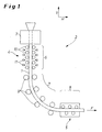
- Fig. 1 schematically a continuous casting 2 is shown.
- Liquid metallic material emerges vertically downwards as a strand 1 from a mold 3 in the conveying direction F and is gradually redirected from the vertical V to the horizontal H along a casting arc section.
- a vertical strand guide 4 having a number of rollers 10 which guide the metal strip 1.
- a number of rollers 9 act as a means for bending the metal strip 1 from the vertical V to the horizontal H.
- this is a straightening driver which subjects the metal strip 1 to mechanical straightening by means of mechanical deformation and can also be provided with a rolling process, which is usually followed.
- the area of the metal strip from the exit from the mold 3 to the mechanical deformation is subdivided into three sections: in a first section 6
- a second section 7 virtually no more cooling is made, and located in the metal strip 1 heat warms the cooled surface of the metal strip 1 again.
- the mechanical deformation takes place.
- the exemplary embodiment shows that the first section 6 is again subdivided into subsections. This allows in a simple manner an intermittent cooling in the first section 6, namely an intensive cooling in a first section and a weaker or reduced or even no cooling in the at least one further follower section, which in turn can then be followed by an intensive cooling section and so on.
- the cooling of the metal strip 1 is carried out with first coolants 11 and second coolants 12, as is best in Fig. 2 can be seen.
- the first cooling means 11 work so intensively that a large cooling capacity is present.
- the second coolant 12 is conventional and per se known coolant, which are used in previously known continuous casting.
- the design of the coolant 11 is carried out so that the cooling of the metal strip 1 in the first section 6, in particular in the immediately following part of the mold 3, its in the extension direction F uppermost or frontmost coolant for descaling and thus cleaning the surfaces of the metal strip 1
- High pressure switchable with a heat transfer coefficient between 3,000 and 10,000 W / (m 2 K) takes place. In this case, the majority of the cooling goes back to the first coolant 11.
- the heat transfer coefficient (symbol ⁇ ), also called heat transfer coefficient or heat transfer coefficient, is a proportionality factor which determines the intensity of the heat transfer at a surface.
- the heat transfer coefficient here describes the ability of a gas or a liquid to dissipate energy from the surface of a substance or to deliver it to the surface. It depends, among other things, on the specific heat, the density and the thermal conductivity coefficient of the heat-dissipating and the heat-delivering medium. The calculation of the coefficient for heat conduction usually takes place via the temperature difference of the media involved.
- the factors mentioned immediately show that the design of the intensity of the cooling has direct effects on the heat transfer coefficient.
- the cooling capacity can be influenced for example by changing the horizontal distance between the cooling means 11 and 12 and the metal strip 1; it becomes lower, the greater the distance.
- the mentioned coolant 11 are not needed for every application. Therefore, they are - how it looks Fig. 2 emerges - arranged displaceably in the vertical direction, with corresponding means of movement are not shown. Shown are the coolant 11 in solid lines in its active position, wherein the ejected jet cooling water takes the outlined course.
- the coolant 11 can be moved vertically in the position shown in dashed lines, so that a classic, lower, d. H. less intensive cooling by the coolant 12 is accomplished.
- the cooling means 11 have a housing 13, on whose side facing the metal strip 1, two nozzles 14 and 15 or rows of nozzles extending perpendicularly to the plane of the drawing over the metal strip 1 are arranged.
- the housing 13 has in its interior according to two chambers 16, 17 which are each fluidly connected to a water supply line.
- the nozzles 14 and 15 are designed differently, so that different amounts of water currents can be directed to the metal strip 1 - depending on the technological need to achieve a scale-free as possible and thus cleaned surface of Metallbandes1.
- the nozzles may also be designed as nozzle bars, d. H. as a beam which extends across the width of the metal strip 1 and passes cooling water from a number of nozzle openings on the strip surface.
- the proposed device for intensive cooling thus has a housing which can be pushed with a small distance between the continuous casting guide rollers 10 and thus forms a cooling channel.
- the housing 13 can be protected from destruction by a fender (not shown) in the event of a breakthrough, so that it can be reused in this case.
- a fender not shown
- the cooling effect can be influenced. Further influence on the cooling effect can be achieved by the construction of the housing and the nozzles 14, 15.
- a subcooling of the edge region of the metal strip can also be avoided by switching on and off of nozzle groups.
- spray nozzles can also be used. These should be distributed close to each other across the width of the metal strip to achieve the necessary cooling and cooling and grain refining and descaling effect associated therewith. By switching these groups on and off, subcooling of the edges can also be avoided.
- the nozzles can be deactivated, swung away, moved away or the flow of cooling medium (water) can be lowered to ensure standard cooling.
- additional cooling consisting of several provided with spray nozzles spray bar are used with a separate water supply.
- the additional spray bars are only switched on when needed.
- subcooling of the edges can also be avoided here by switching on and off of nozzle groups.
- Such nozzles are not used for the present invention because of their excessive cooling effect and the associated low surface temperature of the surface of the metal strip or they are not useful here.
- the core idea according to the invention can therefore be seen in the fact that intensive cooling takes place in the area of secondary cooling, in particular in thin slab plants, in order to achieve a cleaning of the surface of the slab in which the intensive cooling begins shortly after the mold, viewed in the conveying direction.
- the cooling ends so early that reheating can take place above the temperature Ac3 or Ar3 before mechanical stresses occur, as is the case, for example, with the bending driver.
- the aim is to have no or only a small excretion on the grain boundaries.
- the proposed device for intensive cooling has a significantly higher cooling effect than is otherwise the case with the secondary cooling of a continuous casting plant.
- the usual heat transfer coefficients are between 500 W / (m 2 K) and 2,500 W / (m 2 K).
- descaling plants are known in which a cooling device is used which realizes heat transfer numbers of more than 20,000 W / (m 2 K).
- the heat transfer rates required here are - as already indicated above - material-dependent and also dependent on the casting speed. They result from the maximum cooling rate at which no martensite or interstitial structure is yet produced.
- the cooling rate is about 2,500 ° C / min, which corresponds to a heat transfer coefficient of about 5,500 W / (m 2 K) at a casting speed of 5.0 m / min.
- the intensity of the cooling can be varied by the number of nozzles arranged side by side. Furthermore, it is also possible to use additional nozzle bars to conventional spray cooling devices.
- the length of the intensive cooling - viewed in the conveying direction F - is determined by the solidification structure to 2 mm below the surface of the metal strip. In the case of dendritic solidification, the intensive cooling length is lengthened by about a factor of 2 to 3 compared with the length in the case of globulitic solidification.
- the heat transfer coefficient also results from the design of the coolant, in this case in particular the first coolant 11.
- the number is selected specifically in the claimed range, since the conditions for intensive cooling of the finished metal strip 1 are optimal and at the same time a largely scaling belt surface can be achieved.
Description
- Die Erfindung betrifft ein Verfahren zum Stranggießen von Brammen-, Dünnbrammen-, Vorblock-, Vorprofil-, Rundprofil-, Rohrprofil- oder Knüppelsträngen und dergleichen aus flüssigem Metall in einer Stranggießanlage, bei dem Metall aus einer Kokille senkrecht nach unten austritt, wobei das Metallband dann entlang einer senkrechten Strangführung vertikal abwärts geführt und dabei gekühlt wird, wobei das Metallband dann aus der vertikalen Richtung in die horizontale Richtung umgebogen wird und wobei im Endbereich der Umbiegung in die horizontale Richtung oder nach der Umbiegung in die horizontale Richtung eine mechanische Umformung des Metallbandes erfolgt. Des weiteren betrifft die Erfindung eine Stranggießanlage, insbesondere zur Durchführung dieses Verfahrens.
- Ein gattungsgemäßes Verfahren zum Stranggießen ist beispielsweise aus der
EP 1 108 485 A1 oder aus derWO 2004/048016 A2 bekannt. Hierbei wird flüssiges Metall, insbesondere Stahl, über eine Kokille senkrecht nach unten ausgebracht, wobei es sich verfestigt und ein Metallband bildet, das allmählich aus der vertikalen Richtung in die horizontale Richtung umgeleitet bzw. umgebogen wird. Unmittelbar unterhalb der Kokille befindet sich eine senkrechte Strangführung, die das noch sehr heiße Metallband zunächst vertikal unten führt. Anschließend wird das Metallband durch entsprechende Walzen bzw. Rollen allmählich in die Horizontale umgebogen. Ist dies erfolgt, schließt sich zumeist ein Richtprozess an, d. h. das Metallband läuft durch eine Richtvorrichtung, in der eine mechanische Verformung des Metallbandes stattfindet. - Ähnliche Lösungen sind in der
JP 63 112058 A WO 03/013763 A EP 0 611 610 A1 , in derDE 22 08 928 A1 , in derDE 24 35 495 A1 , in derDE 25 07 971 A1 , in derEP 0 343 103 A1 , in derEP 1 243 343 B1 , in derEP 1 356 868 B1 und in derEP 1 366 838 A beschrieben. - Der Kühlung des Metallbandes nach seinem Austritt aus der Kokille kommt eine wichtige Bedeutung zu. Die
EP 1 108 485 A1 schlägt hierzu eine Vorrichtung zum Kühlen des Gussstranges in einer Kühlzone vor, in der der Strang mittels Rollenpaaren, die quer zur Strangachse entlang der Strangabzugsrichtung übereinander angeordnet sind, stützend geführt wird, wobei das Aufbringen von Kühlmittel den Strang weiter abkühlt. Zur effizienten Kühlung des Metallbandes umfasst die vorgeschlagene Vorrichtung ein zwischen jeweils zwei übereinander liegenden Rollen angeordnetes kühlmittelförderndes Kühlmittelelement, das sich entlang der Längsachse der Rollen erstreckt und so gestaltet ist, dass zwischen dem jeweiligen Kühlelement und der Rolle sowie dem Kühlelement und dem Strang Spalträume entstehen, wobei das jeweilige Kühlelement mit mindestens einem kühlmittelfördernden, in einen Spaltraum mündenden Kanal versehen ist. - Die
WO 2004/048016 A2 sieht zur optimalen Temperaturführung des gegossenen Metallbandes vor, das über die Auslauftemperatur, die durch Kontrolle der Oberflächentemperatur am Ende der metallurgischen Stranglänge des Gießstrangs ermittelt wird, ein dynamisches Spritzsystem in Form der Wassermengenverteilung und Druckverteilung bzw. Impulsverteilung über die Strangbreite und die Stranglänge funktional zu einer für die Stranglänge und die Strangbreite errechneten Temperaturverlaufskurve gesteuert wird. - Eine Vielzahl weiterer Lösungen beschäftigt sich gleichermaßen mit der Frage, wie ein gegossener Metallstrang effizient und in verfahrenstechnisch richtiger Weise gekühlt werden kann. Hierzu wird auf die
JP 61074763 A JP 9057412 EP 0 650 790 B1 , auf dieUS 6,374,901 B1 , auf dieUS 2002/0129921 A1 ; auf dieEP 0 686 702 B1 , auf dieWO 01/91943 A1 JP 2004167521 JP 2002079356 - Es hat sich herausgestellt, dass neben der verfahrenstechnisch richtigen bzw. effizienten Kühlung des gegossenen Metallbandes dessen Verzunderung eine erhebliche Rolle spielt. Infolge der sehr hohen Temperatur des Metallbandes unmittelbar nach dem Austritt des Metalls aus der Kokille unterliegt das Band einem starken Verzunderungseffekt, der insbesondere die nachfolgenden Prozessschritte nachteilig beeinflusst. Es ist daher anzustreben, dass der Grad der Verzunderung möglichst gering gehalten wird.
- Der Erfindung liegt daher die Aufgabe zugrunde, ein Verfahren der eingangs genannten Art sowie eine entsprechende Vorrichtung derart weiterzuentwickein, dass es möglich wird, neben einer optimalen Kühlung des Metallbandes auch zu erreichen, dass die Verzunderung der Bandoberfläche minimal gehalten wird.
- Die Lösung dieser Aufgabe durch die Erfindung ist verfahrensgemäß dadurch gelöst, dass in Förderrichtung des Metallbandes hinter der Kokille und vor der mechanischen Umformung des Metallbandes in einem ersten Abschnitt eine Kühlung des Metallbandes mit einer Wärmeübergangszahl zwischen 3.000 und 10.000 W/(m2 K) erfolgt, wobei in Förderrichtung nach der Kühlung in einem zweiten Abschnitt durch Wärmeausgleich im Metallband ohne oder mit reduzierter Kühlung der Oberfläche des Metallbandes eine Erwärmung der Oberfläche des Metallbandes auf eine Temperatur über Ac3 bzw. Ar3 erfolgt, wonach in einem dritten Abschnitt die mechanische Umformung erfolgt.
- Wenn nach einem bevorzugten Vorschlag der Erfindung die Oberflächen des Metallbandes vor der Beaufschlagung mit dem Kühlmedium zur Kühlung gesäubert werden, lässt sich die Wirkung der nachfolgend einsetzenden Kühlung weiter verbessern. Das Säubern kann durch Entzundern erfolgen, beispielsweise dadurch, dass die in Strang- bzw. Metallband-Auszugsrichtung einander gegenüberliegeriden, zuerst von dem Metallband/Strang erreichten und somit vordersten bzw. obersten Kühlmittel (Düsen, Düsenbalken od. dgl.) das Kühlmedium unter Hochdruck aufbringen, so dass sich eine Entzunderung ergibt.
- Die mechanische Umformung in dem dritten Abschnitt kann dabei ein Richtprozess des Metallbandes sein oder einen solchen Prozess umfassen. Alternativ oder additiv kann vorgesehen werden, dass die mechanische Umformung in dem dritten Abschnitt ein Walzprozess des Metallbandes ist oder einen solchen Prozess umfaßt.
- Die Kühlung im ersten Abschnitt kann -als Intensivkühlung ausgebildet - auf den Bereich der senkrechten Strangführung beschränkt werden. In diesem Zusammenhang ist anzumerken, dass der Begriff der senkrechten Strangführung auch umfassen soll, dass das Metallband weitgehend vertikal geführt wird.
- Die Kühlung im ersten Abschnitt kann auch intermittierend erfolgen, wobei das Metallband/der Strang abwechselnd intensiv und schwach gekühlt wird, z.B. durch Veränderung der Kühlmediumbeaufschlagungsdichte [ I: min:m2] und/oder Einstellung unterschiedlicher Abstände der Kühlmittel zum Metallband.
- Die vorgeschlagene Stranggießanlage zum Stranggießen von Brammen-, Dünnbrammen-, Vorblock-, Vorprofil-, Rundprofil-, Rohrprofil- oder Knüppelsträngen und dergleichen aus flüssigem Metall, mit einer Kokille, aus der das Metall senkrecht nach unten austritt, einer unterhalb der Kokille angeordneten senkrechten Strangführung und Mitteln zum Umbiegen des Metallbandes aus der vertikalen Richtung in die horizontale Richtung, wobei im Endbereich der Umbiegung in die horizontale Richtung oder nach der Umbiegung in die horizontale Richtung mechanische Umformmittel für das Metallband angeordnet sind, zeichnet sich erfindungsgemäß dadurch aus, dass die senkrechte Strangführung eine Anzahl in Förderrichtung des Metallbandes beiderseitig des Metallbandes angeordnete Rollen aufweist, wobei im Bereich der Rollen erste Kühlmittel angeordnet sind, mit denen ein Kühlfluid auf die Oberfläche des Metallbandes aufgebracht werden kann, wobei die Kühlmittel in vertikale und/oder horizontale Richtung verschieblich angeordnet sind und wobei zusätzliche zweite Kühlmittel im Bereich der senkrechten Strangführung ortsfest angeordnet sind
- Alternativ oder ergänzend können die Kühlmittel vorteilhaft oszillierbar ausgebildet sein.
- Die ersten und/oder die zweiten Kühlmittel können ein Gehäuse aufweisen, aus dem das Kühlfluid mittels mindestens einer Düse aufgebracht wird. Das Kühlfluid kann aus dem Gehäuse mittels zweier Düsen oder Düsenreihen aufgebracht werden.
- Gemäß dem Erfindungsvorschlag erfolgt im Bereich der Sekundärkühlung des Metallbandes eine Kühlung mit definierter Intensität, die so gewählt ist, dass einerseits ein qualitativ hochwertiges Metallband produziert werden kann, das die gewünschte Gefügestruktur und Gefügezusammensetzung aufweist, dass andererseits aber auch der Grad der Verzunderung der Bandoberfläche minimal gehalten werden kann.
- Durch den Vorschlag wird auch die Anreicherung von unerwünschten Begleiterscheinungen an der Bandoberfläche vermindert.
- Durch die vorgeschlagene Vorgehensweise entsteht ein so hinreichender Thermoschock, dass sich auf der Oberfläche des Metallbandes befindliche Oxidschichten abtrennen und fortgespült werden. Das führt zu einer gesäuberten Strangoberfläche, was für eine gleichmäßige Abkühlung des Metallbandes und auch für eine mögliche Aufheizung im Tunnelofen von Vorteil ist.
- Das vorgeschlagene Verfahren vermindert die Gefahr durch Ausscheidungen oder von so genannter "Hot Shortness", so dass auch diesbezüglich Vorteile erzielt werden. Durch die für den Thermoschock notwendige Absenkung der Oberflächentemperatur - diese sollte die Martensitstarttemperatur nicht unterschreiten - erfolgt eine Umwandlung des Austenits im Metallband in Ferrit, verbunden mit einer Kornfeinung. Bei der sich anschließenden Wiedererwärmung infolge des großen Temperaturgradienten zwischen Strangoberfläche und Kern des Metallbandes erfolgt eine Rückumwandlung des feinen Ferrits in Austenit mit kleinen Körnern. Bei diesen Umwandlungen werden die Aluminiumnitride (AIN) oder andere Ausscheidungen überwachsen, und auf den Korngrenzen befinden sich prozentual weniger Aluminiumnitride als bei dem großen Austenitkorn vor der Umwandlung. Das feinere Gefüge ist daher weniger rissanfällig, wenn Ausscheidungen vorliegen sollten.
- In der Strangführung unterhalb der Kokille ist der Bereich für die Intensivkühlung vorgesehen, damit die Wiedererwärmung möglichst früh erfolgen kann. Die Ferrit-Umwandlung und die anschließende Umwandlung in Austenit sollen vor der mechanischen Belastung der Strangoberfläche, beispielsweise in den Biegetreibern, erfolgen. Durch diese Maßnahme wird die Gefahr der Rissbildung reduziert, die infolge der Temperaturserokung des Stranges durch den Thermoschock besteht. Eine Ausführungsform des Verfahrens sieht vor, dass die genannte (Intensiv)-Kühlung etwa ein Viertel bis ein Drittel des (Bogen-)Weges von der Kokille bis zur mechanischen Umformung umfasst, woran sich ca. drei Viertel bzw. zwei Drittel dieses Weges anschließen, auf denen nicht mehr oder nur reduziert gekühlt wird.
- Die erfindungsgemäße vorgesehene Intensivkühlung kann zwischen den Strangführungsrollen angeordnet sein und sich je nach gewünschter Kühlwirkung über einen längeren Bereich der Strangführung erstrecken. Es kann - wie erwährt - auch vorteilhaft sein, die Intensivkühlung intermittierend anzuwenden, um die Oberfläche insbesondere bei rissempfindlichen Werkstoffen nicht zu sehr zu unterkühlen.
- Damit kann auch die Warmbrüchigkeit, d. h. die Rissbildung an der Brammenoberfläche, vermindert werden, die insbesondere durch einen hohen Kupfergehalt im Material entstehen kann. Dies ist insbesondere bei Schrott als Ausgangsmaterial relevant, der mitunter einen entsprechend hohen Kupfergehalt aufweist.
- In der Zeichnung sind Ausführungsbeispiele der Erfindung dargestellt. Es zeigen:
- Fig. 1
- schematisch eine Stranggießanlage in der Seitenansicht mit der Dar- stellung einiger der Komponenten der Anlage;
- Fig. 2
- einen vergrößerten Ausschnitt aus
Fig. 1 , nämlich den rechten Ast der senkrechten Strangführung mit ersten und zweiten Kühlmitteln; - Fig. 3
- einen weiter vergrößerten Ausschnitt aus
Fig. 2 mit zwei Rollen und einem dazwischen angeordnetem Kühlmittel; und - Fig. 4
- das Kühlmittel gemäß
Fig. 3 im Detail. - In
Fig. 1 ist schematisch eine Stranggießanlage 2 dargestellt. Flüssiges metallisches Material tritt vertikal nach unten als Strang bzw. Metallband 1 aus einer Kokille 3 in Förderrichtung F aus und wird entlang eines Gießbogenabschnitts allmählich von der Vertikalen V in die Horizontale H umgeleitet. Unmittelbar unterhalb der "Kokille 3 befindet sich eine senkrechte Strangführung 4, die eine Anzahl Rollen 10 aufweist, die das Metallband 1 nach unten führen. Eine Anzahl Rollen 9 fungieren als Mittel zum Umbiegen des Metallbandes 1 von der Vertikalen V in die Horizontale H. Nach erfolgter Umbiegung trifft das Metallband 1 in Mitteln 5 zur mechanischen Umformung ein. Vorliegend handelt es sich hierbei um einen Richttreiber, der das Metallband 1 durch mechanische Umformung einem Richtprozess unterzieht. Vorgesehen werden kann auch ein Walzprozess, der sich zumeist anschließt. - Der Bereich des Metallbandes vom Austritt aus der Kokille 3 bis zur mechanischen Umformung ist in drei Abschnitte unterteilt: In einem ersten Abschnitt 6 erfolgt eine Intensivkühlung des heißen Metallbandes 1, in einem zweiten Abschnitt 7 wird praktisch keine Kühlung mehr vorgenommen, und die sich im Metallband 1 befindliche Wärme wärmt die gekühlte Oberfläche des Metallbandes 1 wieder auf. Vorrangig im dritten Abschnitt 8, aber auch bereits schon im zweiten Abschnitt 7, findet dann schließlich die mechanische Umformung statt. Das Ausführungsbeispiel zeigt, dass der erste Abschnitt 6 in sich nochmals in Teilabschnitte unterteilt ist. Das ermöglicht in einfacher Weise eine intermittierende Kühlung in dem ersten Abschnitt 6, nämlich eine Intensivkühlung in einem ersten Teilabschnitt und eine schwächere bzw. reduzierte oder auch gar keine Kühlung in dem zumindest einen weiteren Folgeteilabschnitt, dem sich nämlich wiederum ein Intensivkühlabschnitt usw. anschließend kann.
- Die Kühlung des Metallbandes 1 erfolgt mit ersten Kühlmitteln 11 und zweiten Kühlmitteln 12, wie es am besten in
Fig. 2 gesehen werden kann. Die ersten Kühlmitteln 11 arbeiten so intensiv, dass eine große Kühlleistung vorliegt. Bei den zweiten Kühlmitteln 12 handelt es sich um übliche und an sich vorbekannte Kühlmittel, die bei vorbekannten Stranggießanlagen eingesetzt werden. Die Auslegung der Kühlmittel 11 erfolgt so, dass die Kühlung des Metallbandes 1 im ersten Abschnitt 6, insbesondere in dem sich der Kokille 3 unmittelbar anschließenden Teilabschnitt, dessen in Auszugsrichtung F obersten bzw. vordersten Kühlmittel zur Entzunderung und damit Säuberung der Oberflächen des Metallbandes 1 auf Hochdruck umschaltbar sind, mit einer Wärmeübergangszahl zwischen 3.000 und 10.000 W/(m2 K) erfolgt. Dabei geht der überwiegende Anteil der Kühlung auf die ersten Kühlmittel 11 zurück. - Zur genannten Wärmeübergangszahl sei bemerkt: Die Wärmeübergangszahl (Formelzeichen α), auch Wärmeübergangskoeffizient oder Wärmeübertragungskoeffizient genannt, ist ein Proportionalitätsfaktor, der die Intensität des Wärmeübergangs an einer Oberfläche bestimmt. Der Wärmeübergangskoeffizient beschreibt hierbei die Fähigkeit eines Gases oder einer Flüssigkeit, Energie von der Oberfläche eines Stoffes abzuführen bzw. an die Oberfläche abzugeben. Sie hängt unter anderem von der spezifischen Wärme, der Dichte und dem Wärmeleitkoeffizienten des wärmeabführenden sowie des wärmeliefernden Mediums ab. Die Berechnung des Koeffizienten für Wärmeleitung erfolgt meist über den Temperaturunterschied der beteiligten Medien. Die genannten Einflussgrößen lassen sofort erkennen, dass die Auslegung der Intensität der Kühlung direkte Auswirkungen auf die Wärmeübergangszahl hat. Die Kühlleistung lässt sich beispielsweise durch Veränderung des horizontale Abstandes zwischen den Kühlmitteln 11 bzw. 12 und dem Metallband 1 beeinflussen; sie wird umso niedriger, je größer der Abstand ist.
- Nach der Kühlung in dem Abschnitt 6 erfolgt im zweiten Abschnitt 7 durch Wärmeausgleich im Metallband 1 ohne weitere Kühlung der Oberfläche des Metallbandes 1 eine Erwärmung der Oberfläche des Metallbandes 1 durch Wärmeausgleich auf eine Temperatur über Ac3 bzw. Ar3. Erst dann erfolgt die mechanische Umformung 5 in den Abschnitten 7 (durch das Abbiegen) und 8, vor allem durch das Richten im Abschnitt 8.
- Die genannten Kühlmittel 11 werden nicht für jeden Anwendungsfall benötigt. Daher sind sie - wie es aus
Fig. 2 hervorgeht - in vertikale Richtung verschieblich angeordnet, wobei entsprechende Bewegungsmittel nicht dargestellt sind. Dargestellt sind die Kühlmittel 11 mit ausgezogenen Linien in ihrer aktiven Position, wobei der ausgestoßene Strahl Kühlwasser den skizzierten Verlauf nimmt. - Wird die Intensivkühlung nicht benötigt, können die Kühlmittel 11 vertikal in die gestrichelt dargestellte Position verfahren werden, so dass eine klassische, geringere, d. h. weniger intensive Kühlung durch die Kühlmittel 12 bewerkstellig wird.
- Andere Maßnahmen zur Beeinflussung (Reduzierung oder Erhöhung) der Kühlleistung bestehen darin, den Abstand zwischen den Kühlmitteln 11, 12 und dem Metallband 1 durch horizontales Verschieben zu verändern und/oder die Kühlmittel 11, 12 oszillieren zu verstellen.
- Nicht dargestellt sind entsprechende Leitungssysteme mit Ventilen, so dass der jeweils benötigte Strom Kühlwasser eingestellt bzw. geschalten werden kann.
- In den
Fig. 3 und 4 wird eine Variante der Ausbildung der ersten Kühlmittel 11 näher dargestellt. Die Kühlmittel 11 weisen ein Gehäuse 13 auf, an dessen dem Metallband 1 zugewandter Seite zwei Düsen 14 und 15 bzw. sich normal auf die Zeichenebene quer über das Metallband 1 erstreckende Düsenreihen angeordnet sind. Das Gehäuse 13 weist in seinem Inneren entsprechend zwei Kammern 16, 17 auf, die jeweils fluidisch mit einer Wasserversorgungsleitung in Verbindung stehen. Die Düsen 14 und 15 sind dabei unterschiedlich ausgeführt, so dass unterschiedlich starke Wasserströme auf das Metallband 1 geleitet werden können - in Abhängigkeit der technologischen Notwendigkeit zur Erzielung einer möglichst zunderfreien und damit gesäuberten Oberfläche des Metallbandes1. - Die Düsen können auch als Düsenbalken ausgebildet sein, d. h. als Balken, der sich quer über die Breite des Metallbandes 1 erstreckt und aus einer Anzahl Düsenöffnungen Kühlwasser auf die Bandoberfläche leitet.
- Die vorgeschlagene Vorrichtung für die Intensivkühlung weist also ein Gehäuse auf, das mit geringem Abstand zwischen die Stranggussführungsrollen 10 geschoben werden kann und so einen Kühlkanal bildet. Das Gehäuse 13 kann durch ein Schutzblech (nicht dargestellt) vor der Zerstörung bei einem eventuellen Durchbruch geschützt werden, so dass es in diesem Fall wieder eingesetzt werden kann. Durch Änderung des Abstandes zwischen der Strangoberfläche und dem Gehäuse 13 kann die Kühlwirkung beeinflusst werden. Weitere Einflussmöglichkeiten auf die Kühlwirkung können durch die Konstruktion des Gehäuses und der Düsen 14, 15 erreicht werden.
- So besteht die Möglichkeit, die Düsen in mehrere Gruppen zu unterteilen und die einzelnen Düsengruppen mit einer eigenen Wasserversorgung zu versehen. Durch Zu- bzw. Abschalten einzelner Düsengruppen und/oder durch Änderung des Durchflusses bzw. des Fluiddruckes kann dann die Kühlwirkung variiert werden. Im Falle einer Standardkühlung, d. h. falls Stähle verarbeitet werden, bei denen eine Intensivkühlung nicht sinnvoll ist, kann eine geringere Zahl an Düsen zugeschaltet werden. Eine andere Möglichkeit ist, die Intensivkühlvorrichtung aus dem Sprühbereich der Standardkühlung wegzuschwenken oder wegzufahren.
- Eine Unterkühlung der Kantenbereich des Metallbandes kann ebenfalls durch ein Zu- bzw. Abschalten von Düsengruppen vermieden werden.
- Zur Intensivkühlung können auch Sprühdüsen eingesetzt werden. Diese sollten nahe aneinander über die Breite des Metallbandes verteilt werden, um die notwendige Abkühlung und die notwendige Abkühlung und die damit verbundene Kornfeinung und Entzunderungswirkung zu erzielen. Durch Zu- und Abschalten dieser Gruppen kann auch hier eine Unterkühlung der Kanten vermieden werden. Für den Gießbetrieb, bei der eine intensive Kühlung nicht vorteilhaft ist, können die Düsen deaktiviert, weggeschwenkt, weggefahren oder der Durchfluss des Kühlmediums (Wasser) gesenkt werden, um die Standardkühlung zu gewährleisten.
- Vorgesehen kann auch werden, dass zu der vorhandenen Sekundärkühlung eine zusätzliche Kühlung, bestehend aus mehreren mit Sprühdüsen versehenen Sprühbalken mit einer separaten Wasserversorgung eingesetzt werden. Die zusätzlichen Sprühbalken werden dabei nur bei Bedarf eingeschaltet. Ebenfalls kann auch hier durch Zu- und Abschalten von Düsengruppen eine Unterkühlung der Kanten vermieden werden.
- Im Stand der Technik sind für die Entzunderung spezielle Entzunderungsdüsen bekannt, die Wärmeübergangszahlen von mehr als 20.000 W/(m2 K) erreichen.
- Derartige Düsen kommen für die vorliegende Erfindung wegen ihrer zu intensiven Kühlwirkung und der damit verbundenen niedrigen Oberflächentemperatur der Oberfläche des Metallbandes nicht zum Einsatz bzw. sie sind hier nicht brauchbar.
- Der erfindungsgemäße Kerngedanke kann also darin gesehen werden, dass eine Intensivkühlung im Bereich der Sekundärkühlung insbesondere bei Dünnbrammenanlagen erfolgt, um eine Säuberung der Oberfläche der Bramme zu erreichen, bei der die Intensivkühlung kurz nach der Kokille - in Förderrichtung betrachtet - beginnt. Allerdings ist weiter vorgesehen, dass die Kühlung so frühzeitig endet, dass eine Wiedererwärmung über die Temperatur Ac3 bzw. Ar3 erfolgen kann, bevor mechanische Beanspruchungen auftreten, wie es beispielsweise am Biegetreiber der Fall ist. Ziel ist es dabei, keine bzw. eine nur geringe Ausscheidung auf den Korngrenzen.
- Die vorgeschlagene Vorrichtung zur Intensivkühlung weist eine deutlich höhere Kühlwirkung auf, als es sonst bei der Sekundärkühlung einer Stranggießanlage der Fall ist. Bei vorbekannte Anlagen liegen die üblichen Wärmeübergangszahlen zwischen 500 W/(m2 K) und 2.500 W/(m2 K). Andererseits sind Entzunderungsanlagen bekannt, bei denen eine Kühleinrichtung eingesetzt wird, die Wärmeübergangszahlen von mehr als 20.000 W/(m2 K) realisieren.
- Die vorliegend benötigten Wärmeübergangszahlen sind - wie bereits oben angedeutet - werkstoffabhängig und auch abhängig von der Gießgeschwindigkeit. Sie ergeben sich aus der maximalen Abkühlgeschwindigkeit, bei der noch kein Martensit- oder Zwischenstufengefüge erzeugt wird. Für niedrige Kohlenstoffstähle beträgt die Abkühlungsgeschwindigkeit ca. 2.500 °C/min, was bei einer Gießgeschwindigkeit von 5,0 m/min einer Wärmeübergangszahl von ca. 5.500 W/(m2 K) entspricht.
- Durch ein schnelles Umschalten zwischen Standard- und Intensivkühlung wird die vorgeschlagene Stranggießeinrichtung sehr individuell und flexibel nutzbar.
- Werden die vorgeschlagenen Systeme mit den beschriebenen Kühldüsen eingesetzt, werden infolge der sich bildenden hohen Turbulenz des Wassers zwischen dem Gehäuse der Kühlmittel und dem Metallband bei relativ geringer Wassermenge höhere Wärmeübergangszahlen als bei der konventionellen Sprühkühlung erreicht.
- Die Intensität der Kühlung kann durch die Anzahl der nebeneinander angeordneten Düsen variiert werden. Weiterhin ist es auch möglich, zusätzliche Düsenbalken zu konventionellen Sprühkühlungseinrichtungen einzusetzen.
- Die Länge der Intensivkühlung - in Förderrichtung F betrachtet - wird durch das Erstarrungsgefüge bis 2 mm unter der Oberfläche des Metallbandes bestimmt. Bei einer dendritischen Erstarrung verlängert sich die Intensivkühllänge ca. um den Faktor 2 bis 3 gegenüber der Länge bei einer globulitischen Erstarrung.
- Die Wärmeübergangszahl ergibt sich auch aus der Konstruktion der Kühlmittel, vorliegend insbesondere der ersten Kühlmittel 11. Die Zahl wird gezielt im beanspruchten Bereich gewählt, da hier die Bedingungen zur Intensivkühlung des gefertigten Metallbandes 1 optimal sind und gleichzeitig eine weitgehend zunderfreie Bandoberfläche erzielt werden kann.
-
- 1
- Metallband
- 2
- Stranggießanlage
- 3
- Kokille
- 4
- senkrechte Strangführung
- 5
- mechanische Umformung
- 6
- erster Abschnitt
- 7
- zweiter Abschnitt
- 8
- dritter Abschnitt
- 9
- Mittel zum Umbiegen des Metallbandes
- 10
- Rollen
- 11
- erste Kühlmittel
- 12
- zweite Kühlmittel
- 13
- Gehäuse
- 14
- Düse
- 15
- Düse
- 16
- Kammer
- 17
- Kammer
- V
- vertikale Richtung
- H
- horizontale Richtung
- F
- Förder- bzw. Auszugsrichtung
Claims (10)
- Verfahren zum Stranggießen von Brammen-, Dünnbrammen-, Vorblock-, Vorprofil-, Rundprofil-, Rohrprofil- oder Knüppelsträgen (1) und dergleichen aus flüssigem Metall in einer Stranggießanlage (2), bei dem Metall aus einer Kokille (3) senkrecht nach unten austritt, wobei das Metallband (1) dann entlang einer senkrechten Strangführung (4) vertikal abwärts geführt und dabei gekühlt wird, wobei das Metallband (1) dann aus der vertikalen Richtung (V) in die horizontale Richtung (H) umgebogen wird und wobei im Endbereich der Umbiegung in die horizontale Richtung (H) oder nach der Umbiegung in die horizontale Richtung (H) eine mechanische Umformung (5) des Metallbandes (1) erfolgt,
dadurch gekennzeichnet;
dass in Förderrichtung (F) des Metallbandes (1) hinter der Kokille (3) und vor der mechanischen Umformung (5) des Metallbandes (1) in einem ersten Abschnitt (6) eine Kühlung des Metallbandes (1) mit einer Wärmeübergangszahl zwischen 3.000 und 10.000 W/(m2 K) erfolgt, wobei in Förderrichtung (F) nach der Kühlung in einem zweiten Abschnitt (7) durch Wärmeausgleich im Metallband (1) ohne oder mit reduzierter Kühlung der Oberfläche des Metallbandes (1) eine Erwärmung der Oberfläche des Metallbandes (1) auf eine Temperatur über Ac3 bzw. Ar3 erfolgt, wonach in einem dritten Abschnitt (8) die mechanische Umformung (5) erfolgt. - Verfahren nach Anspruch 1,
dadurch gekennzeichnet,
dass die Oberflächen des Metallbandes (1) unmittelbar vor der Kühlbeaufschlagung gesäubert werden. - Verfahren nach Anspruch 1 oder 2,
dadurch gekennzeichnet,
dass der erste Abschnitt (6) unterteilt ist, wobei das Metallband (1) intermittierend gekühlt wird und in einem der Kokille (3) unmittelbar nachgeschalteten Teilabschnitt intensiv und in mindestens einem Folgeteilabschnitt schwächer sowie dann nachfolgend wieder intensiver gekühlt wird. - Verfahren nach einem der Ansprüche 1 bis 3,
dadurch gekennzeichnet,
dass die mechanische Umformung (5) in dem dritten Abschnitt (8) ein Richtprozess des Metallbandes (1) ist oder einen solchen Prozess umfasst. - Verfahren nach einem der Ansprüche 1 bis 3,
dadurch gekennzeichnet,
dass die mechanische Umformung (5) in dem dritten Abschnitt (8) ein Walzprozess des Metallbandes (1) ist oder einen solchen Prozess umfasst. - Verfahren nach einem der Ansprüche 1 bis 5,
dadurch gekennzeichnet,
dass die Kühlung im ersten Abschnitt (6) auf den Bereich der senkrechten Strangführung (4) beschränkt wird. - Stranggießanlage (2) zum Stranggießen von Brammen-, Dünnbrammen-, Vorblock-, Vorprofil-, Rundprofil-, Rohrprofil- oder Knüppelsträgen (1) und dergleichen aus flüssigem Metall, mit einer Kokille (3), aus der das Metall senkrecht nach unten austritt, einer unterhalb der Kokille (3) angeordneten senkrechten Strangführung (4) und Mitteln (9) zum Umbiegen des Metallbandes (1) aus der vertikalen Richtung (V) in die horizontale Richtung (H), wobei im Endbereich der Umbiegung in die horizontale Richtung (H) oder nach der Umbiegung in die horizontale Richtung (H) mechanische Umformmittel (5) für das Metallband (1) angeordnet sind, zur Durchführung des Verfahrens nach einem der Ansprüche 1 bis 6,
dadurch gekennzeichnet,
dass die senkrechte Strangführung (4) eine Anzahl in Förderrichtung (F) des Metallbandes (1) beiderseitig des Metallbandes (1) angeordnete Rollen (10) aufweist, wobei im Bereich der Rollen (10) erste Kühlmittel (11) angeordnet sind, mit denen ein Kühlfluid auf die Oberfläche des Metallbandes (1) aufgebracht werden kann, wobei die Kühlmittel (11) in vertikale und/oder horizontale Richtung (V, H) verschieblich angeordnet sind und wobei zusätzliche zweite Kühlmittel (12) im Bereich der senkrechten Strangführung (4) ortsfest angeordnet sind. - Stranggießanlage nach Anspruch 7,
dadurch gekennzeichnet,
dass die Kühlmittel (11) oszillierbar ausgebildet sind. - Stranggießanlage nach Anspruch 7 oder 8,
dadurch gekennzeichnet,
dass die ersten und/oder die zweiten Kühlmittel (11, 12) ein Gehäuse (13) aufweisen, aus dem das Kühlfluid mittels mindestens einer Düse (14, 15) ausgebracht wird. - Stranggießanlage nach Anspruch 9,
dadurch gekennzeichnet,
dass Kühlfluid aus dem Gehäuse (13) mittels zweier Düsen (14, 15) oder Düsenreihen ausgebracht wird.
Priority Applications (1)
| Application Number | Priority Date | Filing Date | Title |
|---|---|---|---|
| PL06841185T PL1937429T3 (pl) | 2006-01-11 | 2006-12-28 | Sposób i urządzenie do odlewania ciągłego |
Applications Claiming Priority (3)
| Application Number | Priority Date | Filing Date | Title |
|---|---|---|---|
| DE102006001464 | 2006-01-11 | ||
| DE102006056683A DE102006056683A1 (de) | 2006-01-11 | 2006-11-30 | Verfahren und Vorrichtung zum Stranggießen |
| PCT/EP2006/012560 WO2007087893A1 (de) | 2006-01-11 | 2006-12-28 | Verfahren und vorrichtung zum stranggiessen |
Publications (2)
| Publication Number | Publication Date |
|---|---|
| EP1937429A1 EP1937429A1 (de) | 2008-07-02 |
| EP1937429B1 true EP1937429B1 (de) | 2009-03-18 |
Family
ID=37909512
Family Applications (1)
| Application Number | Title | Priority Date | Filing Date |
|---|---|---|---|
| EP06841185A Active EP1937429B1 (de) | 2006-01-11 | 2006-12-28 | Verfahren und vorrichtung zum stranggiessen |
Country Status (16)
| Country | Link |
|---|---|
| US (2) | US8596335B2 (de) |
| EP (1) | EP1937429B1 (de) |
| JP (1) | JP5039712B2 (de) |
| KR (1) | KR101037078B1 (de) |
| AT (1) | ATE425827T1 (de) |
| AU (1) | AU2006337470B2 (de) |
| BR (1) | BRPI0620971B1 (de) |
| CA (1) | CA2635128C (de) |
| DE (2) | DE102006056683A1 (de) |
| EG (1) | EG24892A (de) |
| ES (1) | ES2321234T3 (de) |
| MY (1) | MY143585A (de) |
| PL (1) | PL1937429T3 (de) |
| RU (1) | RU2377096C1 (de) |
| TW (1) | TWI382888B (de) |
| WO (1) | WO2007087893A1 (de) |
Cited By (2)
| Publication number | Priority date | Publication date | Assignee | Title |
|---|---|---|---|---|
| DE102014214374A1 (de) | 2014-07-23 | 2016-01-28 | Sms Group Gmbh | Verfahren zur Herstellung eines metallischen Produkts |
| DE102017213842A1 (de) | 2017-08-08 | 2019-02-14 | Sms Group Gmbh | Verfahren und Anlage zum Stranggießen eines metallischen Produkts |
Families Citing this family (16)
| Publication number | Priority date | Publication date | Assignee | Title |
|---|---|---|---|---|
| DE102008032970A1 (de) * | 2008-07-10 | 2010-01-14 | Sms Siemag Aktiengesellschaft | Verfahren zum Abkühlen eines aus einer Stranggießkokille austretenden Stranges |
| US8479802B1 (en) * | 2012-05-17 | 2013-07-09 | Almex USA, Inc. | Apparatus for casting aluminum lithium alloys |
| US8365808B1 (en) | 2012-05-17 | 2013-02-05 | Almex USA, Inc. | Process and apparatus for minimizing the potential for explosions in the direct chill casting of aluminum lithium alloys |
| KR101406652B1 (ko) | 2012-09-05 | 2014-06-11 | 주식회사 포스코 | 냉각노즐 커버장치 |
| JP6462590B2 (ja) | 2013-02-04 | 2019-01-30 | アルメックス ユーエスエー, インコーポレイテッド | 直接チル鋳造のためのプロセスおよび装置 |
| JP5854071B2 (ja) * | 2013-03-29 | 2016-02-09 | Jfeスチール株式会社 | 鋼の連続鋳造方法 |
| DE102013212952A1 (de) | 2013-07-03 | 2015-01-22 | Sms Siemag Ag | Vorrichtung und Verfahren zum Stützen eines Stranges beim Stranggießen |
| US9936541B2 (en) | 2013-11-23 | 2018-04-03 | Almex USA, Inc. | Alloy melting and holding furnace |
| CN107206474B (zh) * | 2015-01-15 | 2019-07-09 | 日本制铁株式会社 | 铸坯的连续铸造方法 |
| KR101736574B1 (ko) * | 2015-06-04 | 2017-05-17 | 주식회사 포스코 | 응고 장치 |
| JP6831461B2 (ja) * | 2016-11-18 | 2021-02-17 | エス・エム・エス・グループ・ゲゼルシャフト・ミト・ベシュレンクテル・ハフツング | 連続した帯状の複合材料を製造する方法及び装置 |
| CN109238398A (zh) * | 2018-04-25 | 2019-01-18 | 西安麦特沃金液控技术有限公司 | 一种液位检测装置及液位检测方法 |
| CN110369686A (zh) * | 2019-07-03 | 2019-10-25 | 西安理工大学 | 一种铸铁水平连铸三次喷冷装置 |
| KR20210051247A (ko) | 2019-10-30 | 2021-05-10 | 이준수 | 연속 주조용 세그먼트 모니터링 방법 |
| CN111495971A (zh) * | 2020-05-06 | 2020-08-07 | 义乌聚龙自动化科技有限公司 | 一种铝合金板连铸连轧设备和方法 |
| CN113426970B (zh) * | 2021-06-11 | 2023-02-03 | 一重集团大连工程技术有限公司 | Φ1000mm-Φ2000mm大型圆坯的立式半连续生产装置及其生产工序 |
Family Cites Families (37)
| Publication number | Priority date | Publication date | Assignee | Title |
|---|---|---|---|---|
| US3358358A (en) * | 1964-12-31 | 1967-12-19 | United States Steel Corp | Method of reducing width of metal slabs |
| AT314752B (de) | 1971-04-30 | 1974-04-25 | Voest Ag | Stranggießanlage für Brammen |
| AT323921B (de) | 1973-07-27 | 1975-08-11 | Voest Ag | Kuhleinrichtung für kontinuierlich zu giessende stränge |
| CH580454A5 (de) * | 1974-04-26 | 1976-10-15 | Concast Ag | |
| BE831560A (fr) * | 1975-07-18 | 1976-01-19 | Perfectionnements aux procedes de coulee continue des metaux | |
| JPS6174763A (ja) | 1984-09-17 | 1986-04-17 | Sumitomo Heavy Ind Ltd | 連続鋳造機における鋳片の表面温度制御方法 |
| JPS63112058A (ja) * | 1986-10-28 | 1988-05-17 | Mitsubishi Heavy Ind Ltd | 連続鋳造方法 |
| EP0343103B1 (de) * | 1988-05-19 | 1992-11-11 | Alusuisse-Lonza Services Ag | Verfahren und Vorrichtung zum Kühlen eines Gegenstandes |
| JPH048645A (ja) | 1990-04-26 | 1992-01-13 | Seiko Epson Corp | 自動車電話装置 |
| JPH0480645A (ja) | 1990-07-23 | 1992-03-13 | Nissan Motor Co Ltd | 欠陥検査装置 |
| AT398396B (de) * | 1993-02-16 | 1994-11-25 | Voest Alpine Ind Anlagen | Verfahren zum herstellen eines bandes, vorstreifens oder einer bramme |
| ATE222152T1 (de) | 1993-10-29 | 2002-08-15 | Danieli Off Mecc | Verfahren und vorrichtung zur thermischen oberflächenbehandlung eines stranges |
| DE4416752A1 (de) | 1994-05-13 | 1995-11-16 | Schloemann Siemag Ag | Verfahren und Produktionsanlage zur Erzeugung von Warmbreitband |
| JPH08132207A (ja) * | 1994-11-09 | 1996-05-28 | Sumitomo Metal Ind Ltd | 鋼の連続鋳造時における表面割れ抑制方法 |
| JPH08267205A (ja) * | 1995-03-31 | 1996-10-15 | Kawasaki Steel Corp | 連続鋳造機 |
| JP2944476B2 (ja) | 1995-08-29 | 1999-09-06 | 川崎製鉄株式会社 | 鋳片の表面割れを防止した連続鍛圧法 |
| JPH09141408A (ja) | 1995-11-24 | 1997-06-03 | Kawasaki Steel Corp | 連続鋳造の二次冷却方法 |
| JP3058079B2 (ja) | 1996-02-23 | 2000-07-04 | 住友金属工業株式会社 | 鋼の連続鋳造方法 |
| CA2277392C (en) | 1998-07-10 | 2004-05-18 | Ipsco Inc. | Differential quench method and apparatus |
| JP2000233266A (ja) * | 1999-02-15 | 2000-08-29 | Nkk Corp | 表面性状の良好な鋼板の製造方法 |
| DE19931331A1 (de) * | 1999-07-07 | 2001-01-18 | Siemens Ag | Verfahren und Einrichtung zum Herstellen eines Stranges aus Metall |
| DE19960593C2 (de) | 1999-12-16 | 2001-11-22 | Sms Demag Ag | Vorrichtung zum Kühlen eines metallischen Gussstrangs |
| JP3555538B2 (ja) | 2000-02-21 | 2004-08-18 | Jfeスチール株式会社 | 連続鋳造鋳片の直送圧延方法 |
| AT409352B (de) | 2000-06-02 | 2002-07-25 | Voest Alpine Ind Anlagen | Verfahren zum stranggiessen eines metallstranges |
| JP2002079356A (ja) | 2000-09-06 | 2002-03-19 | Daido Steel Co Ltd | 連続鋳造における2次冷却方法 |
| JP3705101B2 (ja) * | 2000-09-12 | 2005-10-12 | 住友金属工業株式会社 | 連続鋳造方法 |
| ES2204774T3 (es) * | 2001-03-22 | 2004-05-01 | Lechler Gmbh | Boquilla rociadora de dos fuidos. |
| JP3702807B2 (ja) * | 2001-04-11 | 2005-10-05 | 住友金属工業株式会社 | 連続鋳造方法 |
| ATE482037T1 (de) * | 2001-04-25 | 2010-10-15 | Jfe Steel Corp | Herstellungsverfahren für ein stranggegossenes stahlprodukt |
| DE10138794A1 (de) | 2001-08-07 | 2003-02-27 | Sms Demag Ag | Verfahren und Anlage zur Produktion von Flach- und Langprodukten |
| DE50211289D1 (de) | 2002-02-28 | 2008-01-10 | Lechler Gmbh | Kühlanordnung für das Walzgerüst einer Stranggussanlage |
| JP2003275852A (ja) | 2002-03-18 | 2003-09-30 | Jfe Steel Kk | 鋼の連続鋳造方法および装置 |
| ATE255468T1 (de) * | 2002-04-18 | 2003-12-15 | Lechler Gmbh | Zweistoffsprühdüse mit wechselbarem einsatz |
| JP4042541B2 (ja) | 2002-11-19 | 2008-02-06 | Jfeスチール株式会社 | 連続鋳造鋳片の二次冷却装置および二次冷却方法 |
| DE10255550B3 (de) | 2002-11-28 | 2004-01-22 | Sms Demag Ag | Verfahren und Einrichtung zum Stranggießen von Brammen-, Dünnbrammen-, Vorblock-, Vorprofil-, Knüppelsträngen und dgl. aus flüssigem Metall, insbesondere aus Stahlwerkstoff |
| JP4321325B2 (ja) | 2004-03-29 | 2009-08-26 | Jfeスチール株式会社 | 連続鋳造鋳片の二次冷却方法 |
| AT503526B1 (de) | 2006-04-25 | 2008-07-15 | Voest Alpine Ind Anlagen | Spritzdüsen-verstelleinrichtung |
-
2006
- 2006-11-30 DE DE102006056683A patent/DE102006056683A1/de not_active Withdrawn
- 2006-12-28 MY MYPI20082460A patent/MY143585A/en unknown
- 2006-12-28 RU RU2008132828/02A patent/RU2377096C1/ru not_active IP Right Cessation
- 2006-12-28 BR BRPI0620971-8A patent/BRPI0620971B1/pt not_active IP Right Cessation
- 2006-12-28 PL PL06841185T patent/PL1937429T3/pl unknown
- 2006-12-28 ES ES06841185T patent/ES2321234T3/es active Active
- 2006-12-28 EP EP06841185A patent/EP1937429B1/de active Active
- 2006-12-28 AT AT06841185T patent/ATE425827T1/de active
- 2006-12-28 WO PCT/EP2006/012560 patent/WO2007087893A1/de active Application Filing
- 2006-12-28 JP JP2008548950A patent/JP5039712B2/ja not_active Expired - Fee Related
- 2006-12-28 DE DE502006003212T patent/DE502006003212D1/de active Active
- 2006-12-28 CA CA2635128A patent/CA2635128C/en not_active Expired - Fee Related
- 2006-12-28 US US12/087,305 patent/US8596335B2/en not_active Expired - Fee Related
- 2006-12-28 AU AU2006337470A patent/AU2006337470B2/en not_active Ceased
- 2006-12-28 KR KR1020087017402A patent/KR101037078B1/ko not_active IP Right Cessation
- 2006-12-29 TW TW095149753A patent/TWI382888B/zh not_active IP Right Cessation
-
2008
- 2008-07-07 EG EG2008071146A patent/EG24892A/xx active
-
2012
- 2012-01-19 US US13/353,511 patent/US8522858B2/en not_active Expired - Fee Related
Cited By (2)
| Publication number | Priority date | Publication date | Assignee | Title |
|---|---|---|---|---|
| DE102014214374A1 (de) | 2014-07-23 | 2016-01-28 | Sms Group Gmbh | Verfahren zur Herstellung eines metallischen Produkts |
| DE102017213842A1 (de) | 2017-08-08 | 2019-02-14 | Sms Group Gmbh | Verfahren und Anlage zum Stranggießen eines metallischen Produkts |
Also Published As
| Publication number | Publication date |
|---|---|
| TW200732062A (en) | 2007-09-01 |
| CA2635128A1 (en) | 2007-08-09 |
| JP2009522110A (ja) | 2009-06-11 |
| US20090095438A1 (en) | 2009-04-16 |
| DE502006003212D1 (de) | 2009-04-30 |
| PL1937429T3 (pl) | 2009-08-31 |
| RU2377096C1 (ru) | 2009-12-27 |
| JP5039712B2 (ja) | 2012-10-03 |
| ATE425827T1 (de) | 2009-04-15 |
| KR101037078B1 (ko) | 2011-05-26 |
| US8596335B2 (en) | 2013-12-03 |
| MY143585A (en) | 2011-05-31 |
| TWI382888B (zh) | 2013-01-21 |
| DE102006056683A1 (de) | 2007-07-12 |
| EG24892A (en) | 2010-12-13 |
| AU2006337470A1 (en) | 2007-08-09 |
| US20120111527A1 (en) | 2012-05-10 |
| BRPI0620971A2 (pt) | 2011-11-29 |
| BRPI0620971B1 (pt) | 2015-07-21 |
| EP1937429A1 (de) | 2008-07-02 |
| US8522858B2 (en) | 2013-09-03 |
| WO2007087893A1 (de) | 2007-08-09 |
| KR20080081173A (ko) | 2008-09-08 |
| AU2006337470B2 (en) | 2010-02-04 |
| CA2635128C (en) | 2012-07-17 |
| ES2321234T3 (es) | 2009-06-03 |
Similar Documents
| Publication | Publication Date | Title |
|---|---|---|
| EP1937429B1 (de) | Verfahren und vorrichtung zum stranggiessen | |
| EP2349612B2 (de) | Verfahren und stranggiessanlage zum herstellen von dicken brammen | |
| DE3127348C2 (de) | Verfahren zum Kühlen eines Gußstrangs in einer Bogenstranggießanlage | |
| EP2516079B1 (de) | Verfahren zum warmwalzen einer bramme und warmwalzwerk | |
| DE102009036378A1 (de) | Verfahren und Vorrichtung zum Herstellen eines mikrolegierten Stahls, insbesondere eines Röhrenstahls | |
| WO2009141207A1 (de) | Verfahren und stranggiessanlage zum herstellen von dicken brammen | |
| EP3016762B1 (de) | Giesswalzanlage und verfahren zum herstellen von metallischem walzgut | |
| WO2016165933A1 (de) | GIEß-WALZ-ANLAGE UND VERFAHREN ZU DEREN BETRIEB | |
| EP0998993B1 (de) | Verfahren und Vorrichtung zum Kühlen von walzwarmem Walzgut, insbesondere Warmbreitband | |
| EP3291933B1 (de) | Giess-walz-anlage und verfahren zu deren betrieb | |
| WO2015014865A1 (de) | GIEßWALZANLAGE ZUM HERSTELLEN VON METALLBÄNDERN | |
| DE102009030793A1 (de) | Vorrichtung und Verfahren zum horizontalen Gießen eines Metallbandes | |
| DD284175A5 (de) | Verfahren zum kuehlen eines metallischen gegenstandes waehrend des stranggiessens | |
| DE10302265A1 (de) | Verfahren und Vorrichtung zur Erzeugung von stranggegossenen Stahlbrammen | |
| DE60316568T2 (de) | Bandtemperaturregelvorrichtung in einer kontinuierlichen bandgiessanlage | |
| DE19718530B4 (de) | Verfahren zum Kühlen von walzwarmem Walzgut und Vorrichtung zur Durchführung des Verfahrens und Verwendung der Vorrichtung | |
| DE19831998A1 (de) | Stranggießkokille | |
| WO2003013763A1 (de) | Verfahren und anlage zur produktion von flach- und langprodukten | |
| AT525563B1 (de) | Trockengiessen in einer giess-walz-verbundanlage | |
| EP1356879B1 (de) | Stranggiesskokille | |
| AT518450A1 (de) | Verfahren und Kühleinrichtung zum Kühlen eines metallischen Strangs | |
| EP3097995B1 (de) | Segment einer strangführung einer stranggiessanlage und stranggiessanlage | |
| DE3141269A1 (de) | "kuehlverfahren und kuehlvorrichtung fuer langgestrecktes, heisses metallgut, insbesondere fuer stranggegossene knueppel- bzw. bloomstraenge" | |
| DE1458123C (de) | Verfahren zum kontinuierlichen Her stellen von mehreren profilierten Stran gen und Anlage zur Durchfuhrung dieses Verfahrens | |
| WO2002085555A2 (de) | Verfahren und vorrichtung zum stranggiessen von metall |
Legal Events
| Date | Code | Title | Description |
|---|---|---|---|
| PUAI | Public reference made under article 153(3) epc to a published international application that has entered the european phase |
Free format text: ORIGINAL CODE: 0009012 |
|
| 17P | Request for examination filed |
Effective date: 20080517 |
|
| AK | Designated contracting states |
Kind code of ref document: A1 Designated state(s): AT BE BG CH CY CZ DE DK EE ES FI FR GB GR HU IE IS IT LI LT LU LV MC NL PL PT RO SE SI SK TR |
|
| GRAP | Despatch of communication of intention to grant a patent |
Free format text: ORIGINAL CODE: EPIDOSNIGR1 |
|
| GRAS | Grant fee paid |
Free format text: ORIGINAL CODE: EPIDOSNIGR3 |
|
| GRAA | (expected) grant |
Free format text: ORIGINAL CODE: 0009210 |
|
| DAX | Request for extension of the european patent (deleted) | ||
| AK | Designated contracting states |
Kind code of ref document: B1 Designated state(s): AT BE BG CH CY CZ DE DK EE ES FI FR GB GR HU IE IS IT LI LT LU LV MC NL PL PT RO SE SI SK TR |
|
| REG | Reference to a national code |
Ref country code: GB Ref legal event code: FG4D Free format text: NOT ENGLISH |
|
| REG | Reference to a national code |
Ref country code: CH Ref legal event code: EP |
|
| REG | Reference to a national code |
Ref country code: IE Ref legal event code: FG4D Free format text: LANGUAGE OF EP DOCUMENT: GERMAN |
|
| REF | Corresponds to: |
Ref document number: 502006003212 Country of ref document: DE Date of ref document: 20090430 Kind code of ref document: P |
|
| REG | Reference to a national code |
Ref country code: ES Ref legal event code: FG2A Ref document number: 2321234 Country of ref document: ES Kind code of ref document: T3 |
|
| RAP2 | Party data changed (patent owner data changed or rights of a patent transferred) |
Owner name: SMS SIEMAG AG |
|
| PG25 | Lapsed in a contracting state [announced via postgrant information from national office to epo] |
Ref country code: FI Free format text: LAPSE BECAUSE OF FAILURE TO SUBMIT A TRANSLATION OF THE DESCRIPTION OR TO PAY THE FEE WITHIN THE PRESCRIBED TIME-LIMIT Effective date: 20090318 Ref country code: SI Free format text: LAPSE BECAUSE OF FAILURE TO SUBMIT A TRANSLATION OF THE DESCRIPTION OR TO PAY THE FEE WITHIN THE PRESCRIBED TIME-LIMIT Effective date: 20090318 Ref country code: LT Free format text: LAPSE BECAUSE OF FAILURE TO SUBMIT A TRANSLATION OF THE DESCRIPTION OR TO PAY THE FEE WITHIN THE PRESCRIBED TIME-LIMIT Effective date: 20090318 Ref country code: NL Free format text: LAPSE BECAUSE OF FAILURE TO SUBMIT A TRANSLATION OF THE DESCRIPTION OR TO PAY THE FEE WITHIN THE PRESCRIBED TIME-LIMIT Effective date: 20090318 |
|
| NLT2 | Nl: modifications (of names), taken from the european patent patent bulletin |
Owner name: SMS SIEMAG AG Effective date: 20090617 |
|
| PG25 | Lapsed in a contracting state [announced via postgrant information from national office to epo] |
Ref country code: SE Free format text: LAPSE BECAUSE OF FAILURE TO SUBMIT A TRANSLATION OF THE DESCRIPTION OR TO PAY THE FEE WITHIN THE PRESCRIBED TIME-LIMIT Effective date: 20090618 Ref country code: LV Free format text: LAPSE BECAUSE OF FAILURE TO SUBMIT A TRANSLATION OF THE DESCRIPTION OR TO PAY THE FEE WITHIN THE PRESCRIBED TIME-LIMIT Effective date: 20090318 |
|
| REG | Reference to a national code |
Ref country code: PL Ref legal event code: T3 |
|
| NLV1 | Nl: lapsed or annulled due to failure to fulfill the requirements of art. 29p and 29m of the patents act | ||
| REG | Reference to a national code |
Ref country code: HU Ref legal event code: AG4A Ref document number: E005544 Country of ref document: HU |
|
| REG | Reference to a national code |
Ref country code: IE Ref legal event code: FD4D |
|
| PG25 | Lapsed in a contracting state [announced via postgrant information from national office to epo] |
Ref country code: PT Free format text: LAPSE BECAUSE OF FAILURE TO SUBMIT A TRANSLATION OF THE DESCRIPTION OR TO PAY THE FEE WITHIN THE PRESCRIBED TIME-LIMIT Effective date: 20090827 Ref country code: EE Free format text: LAPSE BECAUSE OF FAILURE TO SUBMIT A TRANSLATION OF THE DESCRIPTION OR TO PAY THE FEE WITHIN THE PRESCRIBED TIME-LIMIT Effective date: 20090318 Ref country code: IE Free format text: LAPSE BECAUSE OF FAILURE TO SUBMIT A TRANSLATION OF THE DESCRIPTION OR TO PAY THE FEE WITHIN THE PRESCRIBED TIME-LIMIT Effective date: 20090318 |
|
| PG25 | Lapsed in a contracting state [announced via postgrant information from national office to epo] |
Ref country code: SK Free format text: LAPSE BECAUSE OF FAILURE TO SUBMIT A TRANSLATION OF THE DESCRIPTION OR TO PAY THE FEE WITHIN THE PRESCRIBED TIME-LIMIT Effective date: 20090318 Ref country code: IS Free format text: LAPSE BECAUSE OF FAILURE TO SUBMIT A TRANSLATION OF THE DESCRIPTION OR TO PAY THE FEE WITHIN THE PRESCRIBED TIME-LIMIT Effective date: 20090718 Ref country code: RO Free format text: LAPSE BECAUSE OF FAILURE TO SUBMIT A TRANSLATION OF THE DESCRIPTION OR TO PAY THE FEE WITHIN THE PRESCRIBED TIME-LIMIT Effective date: 20090318 |
|
| PLBI | Opposition filed |
Free format text: ORIGINAL CODE: 0009260 |
|
| PG25 | Lapsed in a contracting state [announced via postgrant information from national office to epo] |
Ref country code: DK Free format text: LAPSE BECAUSE OF FAILURE TO SUBMIT A TRANSLATION OF THE DESCRIPTION OR TO PAY THE FEE WITHIN THE PRESCRIBED TIME-LIMIT Effective date: 20090318 Ref country code: BG Free format text: LAPSE BECAUSE OF FAILURE TO SUBMIT A TRANSLATION OF THE DESCRIPTION OR TO PAY THE FEE WITHIN THE PRESCRIBED TIME-LIMIT Effective date: 20090618 |
|
| 26 | Opposition filed |
Opponent name: SIEMENS VAI METALS TECHNOLOGIES GMBH & CO Effective date: 20091218 |
|
| PLAX | Notice of opposition and request to file observation + time limit sent |
Free format text: ORIGINAL CODE: EPIDOSNOBS2 |
|
| PLAF | Information modified related to communication of a notice of opposition and request to file observations + time limit |
Free format text: ORIGINAL CODE: EPIDOSCOBS2 |
|
| BERE | Be: lapsed |
Owner name: SMS DEMAG A.G. Effective date: 20091231 |
|
| PG25 | Lapsed in a contracting state [announced via postgrant information from national office to epo] |
Ref country code: MC Free format text: LAPSE BECAUSE OF NON-PAYMENT OF DUE FEES Effective date: 20100701 |
|
| PLBB | Reply of patent proprietor to notice(s) of opposition received |
Free format text: ORIGINAL CODE: EPIDOSNOBS3 |
|
| REG | Reference to a national code |
Ref country code: FR Ref legal event code: ST Effective date: 20100831 |
|
| PG25 | Lapsed in a contracting state [announced via postgrant information from national office to epo] |
Ref country code: BE Free format text: LAPSE BECAUSE OF NON-PAYMENT OF DUE FEES Effective date: 20091231 Ref country code: FR Free format text: LAPSE BECAUSE OF NON-PAYMENT OF DUE FEES Effective date: 20091231 Ref country code: GR Free format text: LAPSE BECAUSE OF FAILURE TO SUBMIT A TRANSLATION OF THE DESCRIPTION OR TO PAY THE FEE WITHIN THE PRESCRIBED TIME-LIMIT Effective date: 20090619 |
|
| PLAY | Examination report in opposition despatched + time limit |
Free format text: ORIGINAL CODE: EPIDOSNORE2 |
|
| PLAH | Information related to despatch of examination report in opposition + time limit modified |
Free format text: ORIGINAL CODE: EPIDOSCORE2 |
|
| PGFP | Annual fee paid to national office [announced via postgrant information from national office to epo] |
Ref country code: CZ Payment date: 20101227 Year of fee payment: 5 Ref country code: PL Payment date: 20101129 Year of fee payment: 5 |
|
| PLAH | Information related to despatch of examination report in opposition + time limit modified |
Free format text: ORIGINAL CODE: EPIDOSCORE2 |
|
| PG25 | Lapsed in a contracting state [announced via postgrant information from national office to epo] |
Ref country code: LU Free format text: LAPSE BECAUSE OF NON-PAYMENT OF DUE FEES Effective date: 20091228 |
|
| PGFP | Annual fee paid to national office [announced via postgrant information from national office to epo] |
Ref country code: HU Payment date: 20110107 Year of fee payment: 5 |
|
| PLAB | Opposition data, opponent's data or that of the opponent's representative modified |
Free format text: ORIGINAL CODE: 0009299OPPO |
|
| R26 | Opposition filed (corrected) |
Opponent name: SIEMENS VAI METALS TECHNOLOGIES GMBH Effective date: 20091218 |
|
| PLBC | Reply to examination report in opposition received |
Free format text: ORIGINAL CODE: EPIDOSNORE3 |
|
| REG | Reference to a national code |
Ref country code: CH Ref legal event code: PL |
|
| PG25 | Lapsed in a contracting state [announced via postgrant information from national office to epo] |
Ref country code: CY Free format text: LAPSE BECAUSE OF FAILURE TO SUBMIT A TRANSLATION OF THE DESCRIPTION OR TO PAY THE FEE WITHIN THE PRESCRIBED TIME-LIMIT Effective date: 20090318 |
|
| PG25 | Lapsed in a contracting state [announced via postgrant information from national office to epo] |
Ref country code: CH Free format text: LAPSE BECAUSE OF NON-PAYMENT OF DUE FEES Effective date: 20101231 Ref country code: LI Free format text: LAPSE BECAUSE OF NON-PAYMENT OF DUE FEES Effective date: 20101231 |
|
| APAH | Appeal reference modified |
Free format text: ORIGINAL CODE: EPIDOSCREFNO |
|
| APBM | Appeal reference recorded |
Free format text: ORIGINAL CODE: EPIDOSNREFNO |
|
| APBP | Date of receipt of notice of appeal recorded |
Free format text: ORIGINAL CODE: EPIDOSNNOA2O |
|
| PLCK | Communication despatched that opposition was rejected |
Free format text: ORIGINAL CODE: EPIDOSNREJ1 |
|
| APBQ | Date of receipt of statement of grounds of appeal recorded |
Free format text: ORIGINAL CODE: EPIDOSNNOA3O |
|
| PG25 | Lapsed in a contracting state [announced via postgrant information from national office to epo] |
Ref country code: CZ Free format text: LAPSE BECAUSE OF NON-PAYMENT OF DUE FEES Effective date: 20111228 |
|
| PG25 | Lapsed in a contracting state [announced via postgrant information from national office to epo] |
Ref country code: HU Free format text: LAPSE BECAUSE OF NON-PAYMENT OF DUE FEES Effective date: 20111229 |
|
| REG | Reference to a national code |
Ref country code: PL Ref legal event code: LAPE |
|
| PG25 | Lapsed in a contracting state [announced via postgrant information from national office to epo] |
Ref country code: PL Free format text: LAPSE BECAUSE OF NON-PAYMENT OF DUE FEES Effective date: 20111228 |
|
| PGFP | Annual fee paid to national office [announced via postgrant information from national office to epo] |
Ref country code: TR Payment date: 20131126 Year of fee payment: 8 |
|
| PGFP | Annual fee paid to national office [announced via postgrant information from national office to epo] |
Ref country code: ES Payment date: 20141218 Year of fee payment: 9 |
|
| RAP2 | Party data changed (patent owner data changed or rights of a patent transferred) |
Owner name: SMS GROUP GMBH |
|
| PLAB | Opposition data, opponent's data or that of the opponent's representative modified |
Free format text: ORIGINAL CODE: 0009299OPPO |
|
| REG | Reference to a national code |
Ref country code: DE Ref legal event code: R082 Ref document number: 502006003212 Country of ref document: DE Representative=s name: HEMMERICH & KOLLEGEN, DE Ref country code: DE Ref legal event code: R081 Ref document number: 502006003212 Country of ref document: DE Owner name: SMS GROUP GMBH, DE Free format text: FORMER OWNER: SMS SIEMAG AKTIENGESELLSCHAFT, 40237 DUESSELDORF, DE |
|
| PLAB | Opposition data, opponent's data or that of the opponent's representative modified |
Free format text: ORIGINAL CODE: 0009299OPPO |
|
| R26 | Opposition filed (corrected) |
Opponent name: SIEMENS VAI METALS TECHNOLOGIES GMBH Effective date: 20091218 |
|
| REG | Reference to a national code |
Ref country code: DE Ref legal event code: R100 Ref document number: 502006003212 Country of ref document: DE |
|
| APBU | Appeal procedure closed |
Free format text: ORIGINAL CODE: EPIDOSNNOA9O |
|
| R26 | Opposition filed (corrected) |
Opponent name: PRIMETALS TECHNOLOGIES AUSTRIA GMBH Effective date: 20091218 |
|
| PLBN | Opposition rejected |
Free format text: ORIGINAL CODE: 0009273 |
|
| STAA | Information on the status of an ep patent application or granted ep patent |
Free format text: STATUS: OPPOSITION REJECTED |
|
| 27O | Opposition rejected |
Effective date: 20150916 |
|
| PG25 | Lapsed in a contracting state [announced via postgrant information from national office to epo] |
Ref country code: ES Free format text: LAPSE BECAUSE OF NON-PAYMENT OF DUE FEES Effective date: 20151229 |
|
| PG25 | Lapsed in a contracting state [announced via postgrant information from national office to epo] |
Ref country code: TR Free format text: LAPSE BECAUSE OF NON-PAYMENT OF DUE FEES Effective date: 20151228 |
|
| REG | Reference to a national code |
Ref country code: ES Ref legal event code: FD2A Effective date: 20180628 |
|
| PGFP | Annual fee paid to national office [announced via postgrant information from national office to epo] |
Ref country code: GB Payment date: 20201223 Year of fee payment: 15 |
|
| GBPC | Gb: european patent ceased through non-payment of renewal fee |
Effective date: 20211228 |
|
| PG25 | Lapsed in a contracting state [announced via postgrant information from national office to epo] |
Ref country code: GB Free format text: LAPSE BECAUSE OF NON-PAYMENT OF DUE FEES Effective date: 20211228 |
|
| P01 | Opt-out of the competence of the unified patent court (upc) registered |
Effective date: 20230707 |
|
| PGFP | Annual fee paid to national office [announced via postgrant information from national office to epo] |
Ref country code: IT Payment date: 20231228 Year of fee payment: 18 Ref country code: DE Payment date: 20231214 Year of fee payment: 18 Ref country code: AT Payment date: 20231221 Year of fee payment: 18 |